RU2447850C2 - Electronic interlocks and surgical stapler comprising electronic interlocks - Google Patents
Electronic interlocks and surgical stapler comprising electronic interlocksDownload PDFInfo
- Publication number
- RU2447850C2 RU2447850C2RU2007103538/14ARU2007103538ARU2447850C2RU 2447850 C2RU2447850 C2RU 2447850C2RU 2007103538/14 ARU2007103538/14 ARU 2007103538/14ARU 2007103538 ARU2007103538 ARU 2007103538ARU 2447850 C2RU2447850 C2RU 2447850C2
- Authority
- RU
- Russia
- Prior art keywords
- switch
- brackets
- cutting
- surgical apparatus
- motor
- Prior art date
Links
- 238000005520cutting processMethods0.000claimsabstractdescription102
- 239000012636effectorSubstances0.000claimsabstractdescription79
- 238000009434installationMethods0.000claimsdescription5
- 238000000605extractionMethods0.000claims1
- 238000000034methodMethods0.000abstractdescription5
- 239000003814drugSubstances0.000abstractdescription3
- 239000000126substanceSubstances0.000abstract1
- 230000033001locomotionEffects0.000description25
- 230000005540biological transmissionEffects0.000description9
- 230000009471actionEffects0.000description8
- 239000004744fabricSubstances0.000description8
- 230000007246mechanismEffects0.000description8
- 230000006870functionEffects0.000description6
- 230000003014reinforcing effectEffects0.000description5
- 238000010304firingMethods0.000description4
- 230000002787reinforcementEffects0.000description4
- 230000004044responseEffects0.000description4
- 238000000926separation methodMethods0.000description4
- 230000008901benefitEffects0.000description3
- 238000010586diagramMethods0.000description3
- 238000001415gene therapyMethods0.000description3
- 239000000463materialSubstances0.000description3
- 238000003825pressingMethods0.000description3
- 230000005355Hall effectEffects0.000description2
- 235000014676Phragmites communisNutrition0.000description2
- 230000003044adaptive effectEffects0.000description2
- 239000000853adhesiveSubstances0.000description2
- 230000001070adhesive effectEffects0.000description2
- 230000003321amplificationEffects0.000description2
- 230000015572biosynthetic processEffects0.000description2
- 239000003795chemical substances by applicationSubstances0.000description2
- 238000007906compressionMethods0.000description2
- 230000006835compressionEffects0.000description2
- 238000001514detection methodMethods0.000description2
- 239000003989dielectric materialSubstances0.000description2
- 238000002224dissectionMethods0.000description2
- 238000012377drug deliveryMethods0.000description2
- 229920001746electroactive polymerPolymers0.000description2
- 230000005281excited stateEffects0.000description2
- 230000002439hemostatic effectEffects0.000description2
- 230000013011matingEffects0.000description2
- 229910052751metalInorganic materials0.000description2
- 239000002184metalSubstances0.000description2
- 238000012986modificationMethods0.000description2
- 230000004048modificationEffects0.000description2
- 239000002991molded plasticSubstances0.000description2
- 238000003199nucleic acid amplification methodMethods0.000description2
- 239000004033plasticSubstances0.000description2
- 230000001960triggered effectEffects0.000description2
- 238000002604ultrasonographyMethods0.000description2
- 244000187656Eucalyptus cornutaSpecies0.000description1
- HBBGRARXTFLTSG-UHFFFAOYSA-NLithium ionChemical compound[Li+]HBBGRARXTFLTSG-UHFFFAOYSA-N0.000description1
- 230000004913activationEffects0.000description1
- 230000000740bleeding effectEffects0.000description1
- 230000000903blocking effectEffects0.000description1
- 238000013461designMethods0.000description1
- 230000001627detrimental effectEffects0.000description1
- 238000011161developmentMethods0.000description1
- 230000018109developmental processEffects0.000description1
- 238000006073displacement reactionMethods0.000description1
- 238000009826distributionMethods0.000description1
- 229940079593drugDrugs0.000description1
- -1for exampleSubstances0.000description1
- 238000009472formulationMethods0.000description1
- 238000002347injectionMethods0.000description1
- 239000007924injectionSubstances0.000description1
- 239000004973liquid crystal related substanceSubstances0.000description1
- 229910001416lithium ionInorganic materials0.000description1
- 230000007257malfunctionEffects0.000description1
- 238000004519manufacturing processMethods0.000description1
- 239000000203mixtureSubstances0.000description1
- 238000012544monitoring processMethods0.000description1
- 230000002980postoperative effectEffects0.000description1
- 238000011084recoveryMethods0.000description1
- 230000006641stabilisationEffects0.000description1
- 238000011105stabilizationMethods0.000description1
- 238000001356surgical procedureMethods0.000description1
- 230000001225therapeutic effectEffects0.000description1
- 230000007704transitionEffects0.000description1
Images


Classifications
- A—HUMAN NECESSITIES
- A61—MEDICAL OR VETERINARY SCIENCE; HYGIENE
- A61B—DIAGNOSIS; SURGERY; IDENTIFICATION
- A61B17/00—Surgical instruments, devices or methods
- A—HUMAN NECESSITIES
- A61—MEDICAL OR VETERINARY SCIENCE; HYGIENE
- A61B—DIAGNOSIS; SURGERY; IDENTIFICATION
- A61B17/00—Surgical instruments, devices or methods
- A61B17/068—Surgical staplers, e.g. containing multiple staples or clamps
- A61B17/072—Surgical staplers, e.g. containing multiple staples or clamps for applying a row of staples in a single action, e.g. the staples being applied simultaneously
- A61B17/07207—Surgical staplers, e.g. containing multiple staples or clamps for applying a row of staples in a single action, e.g. the staples being applied simultaneously the staples being applied sequentially
- A—HUMAN NECESSITIES
- A61—MEDICAL OR VETERINARY SCIENCE; HYGIENE
- A61B—DIAGNOSIS; SURGERY; IDENTIFICATION
- A61B17/00—Surgical instruments, devices or methods
- A61B17/068—Surgical staplers, e.g. containing multiple staples or clamps
- A—HUMAN NECESSITIES
- A61—MEDICAL OR VETERINARY SCIENCE; HYGIENE
- A61B—DIAGNOSIS; SURGERY; IDENTIFICATION
- A61B17/00—Surgical instruments, devices or methods
- A61B17/068—Surgical staplers, e.g. containing multiple staples or clamps
- A61B17/072—Surgical staplers, e.g. containing multiple staples or clamps for applying a row of staples in a single action, e.g. the staples being applied simultaneously
- A—HUMAN NECESSITIES
- A61—MEDICAL OR VETERINARY SCIENCE; HYGIENE
- A61B—DIAGNOSIS; SURGERY; IDENTIFICATION
- A61B17/00—Surgical instruments, devices or methods
- A61B17/11—Surgical instruments, devices or methods for performing anastomosis; Buttons for anastomosis
- A61B17/115—Staplers for performing anastomosis, e.g. in a single operation
- A—HUMAN NECESSITIES
- A61—MEDICAL OR VETERINARY SCIENCE; HYGIENE
- A61B—DIAGNOSIS; SURGERY; IDENTIFICATION
- A61B34/00—Computer-aided surgery; Manipulators or robots specially adapted for use in surgery
- A61B34/70—Manipulators specially adapted for use in surgery
- A61B34/76—Manipulators having means for providing feel, e.g. force or tactile feedback
- A—HUMAN NECESSITIES
- A61—MEDICAL OR VETERINARY SCIENCE; HYGIENE
- A61B—DIAGNOSIS; SURGERY; IDENTIFICATION
- A61B17/00—Surgical instruments, devices or methods
- A61B2017/00367—Details of actuation of instruments, e.g. relations between pushing buttons, or the like, and activation of the tool, working tip, or the like
- A61B2017/00398—Details of actuation of instruments, e.g. relations between pushing buttons, or the like, and activation of the tool, working tip, or the like using powered actuators, e.g. stepper motors, solenoids
- A—HUMAN NECESSITIES
- A61—MEDICAL OR VETERINARY SCIENCE; HYGIENE
- A61B—DIAGNOSIS; SURGERY; IDENTIFICATION
- A61B17/00—Surgical instruments, devices or methods
- A61B2017/00681—Aspects not otherwise provided for
- A61B2017/00734—Aspects not otherwise provided for battery operated
- A—HUMAN NECESSITIES
- A61—MEDICAL OR VETERINARY SCIENCE; HYGIENE
- A61B—DIAGNOSIS; SURGERY; IDENTIFICATION
- A61B17/00—Surgical instruments, devices or methods
- A61B17/068—Surgical staplers, e.g. containing multiple staples or clamps
- A61B17/072—Surgical staplers, e.g. containing multiple staples or clamps for applying a row of staples in a single action, e.g. the staples being applied simultaneously
- A61B2017/07214—Stapler heads
- A—HUMAN NECESSITIES
- A61—MEDICAL OR VETERINARY SCIENCE; HYGIENE
- A61B—DIAGNOSIS; SURGERY; IDENTIFICATION
- A61B17/00—Surgical instruments, devices or methods
- A61B17/28—Surgical forceps
- A61B17/29—Forceps for use in minimally invasive surgery
- A61B17/2909—Handles
- A61B2017/2912—Handles transmission of forces to actuating rod or piston
- A61B2017/2923—Toothed members, e.g. rack and pinion
- A—HUMAN NECESSITIES
- A61—MEDICAL OR VETERINARY SCIENCE; HYGIENE
- A61B—DIAGNOSIS; SURGERY; IDENTIFICATION
- A61B17/00—Surgical instruments, devices or methods
- A61B17/28—Surgical forceps
- A61B17/29—Forceps for use in minimally invasive surgery
- A61B2017/2926—Details of heads or jaws
- A61B2017/2927—Details of heads or jaws the angular position of the head being adjustable with respect to the shaft
- A—HUMAN NECESSITIES
- A61—MEDICAL OR VETERINARY SCIENCE; HYGIENE
- A61B—DIAGNOSIS; SURGERY; IDENTIFICATION
- A61B90/00—Instruments, implements or accessories specially adapted for surgery or diagnosis and not covered by any of the groups A61B1/00 - A61B50/00, e.g. for luxation treatment or for protecting wound edges
- A61B90/08—Accessories or related features not otherwise provided for
- A61B2090/0801—Prevention of accidental cutting or pricking
- A61B2090/08021—Prevention of accidental cutting or pricking of the patient or his organs
- A—HUMAN NECESSITIES
- A61—MEDICAL OR VETERINARY SCIENCE; HYGIENE
- A61B—DIAGNOSIS; SURGERY; IDENTIFICATION
- A61B90/00—Instruments, implements or accessories specially adapted for surgery or diagnosis and not covered by any of the groups A61B1/00 - A61B50/00, e.g. for luxation treatment or for protecting wound edges
- A61B90/03—Automatic limiting or abutting means, e.g. for safety
Landscapes
- Health & Medical Sciences (AREA)
- Surgery (AREA)
- Life Sciences & Earth Sciences (AREA)
- Engineering & Computer Science (AREA)
- Medical Informatics (AREA)
- Biomedical Technology (AREA)
- Heart & Thoracic Surgery (AREA)
- Nuclear Medicine, Radiotherapy & Molecular Imaging (AREA)
- Molecular Biology (AREA)
- Animal Behavior & Ethology (AREA)
- General Health & Medical Sciences (AREA)
- Public Health (AREA)
- Veterinary Medicine (AREA)
- Robotics (AREA)
- Surgical Instruments (AREA)
- Materials For Medical Uses (AREA)
Abstract
Description
Translated fromRussianПЕРЕКРЕСТНАЯ ССЫЛКА НА РОДСТВЕННЫЕ ЗАЯВКИCROSS REFERENCE TO RELATED APPLICATIONS
Настоящая заявка связана с нижеперечисленными одновременно поданными заявками на патенты США, которые включены в настоящую заявку путем отсылки:This application is related to the following simultaneous filed US patent applications, which are incorporated into this application by reference:
(1) MOTOR-DRIVEN SURGICAL CUTTING AND FASTENING INSTRUMENT WITH USER FEEDBACK SYSTEM; изобретатели: Frederick E. Shelton, IV, John Ouwerkerk, and Jerome R. Morgan (Attorney Docket No.050519/END5687USNP);(1) MOTOR-DRIVEN SURGICAL CUTTING AND FASTENING INSTRUMENT WITH USER FEEDBACK SYSTEM; inventors: Frederick E. Shelton, IV, John Ouwerkerk, and Jerome R. Morgan (Attorney Docket No.050519 / END5687USNP);
(2) MOTOR-DRIVEN SURGICAL CUTTING AND FASTENING INSTRUMENT WITH LOADING FORCE FEEDBACK; изобретатели: Frederick E. Shelton, IV, John N. Ouwerkerk, Jerome R. Morgan, and Jeffrey S. Swayze (Attorney Docket No.050516/END5692USNP);(2) MOTOR-DRIVEN SURGICAL CUTTING AND FASTENING INSTRUMENT WITH LOADING FORCE FEEDBACK; inventors: Frederick E. Shelton, IV, John N. Ouwerkerk, Jerome R. Morgan, and Jeffrey S. Swayze (Attorney Docket No.050516 / END5692USNP);
(3) MOTOR-DRIVEN SURGICAL CUTTING AND FASTENING INSTRUMENT WITH TACTILE POSITION FEEDBACK; изобретатели; Frederick E. Shelton, IV, John N. Ouwerkerk, Jerome R. Morgan, and Jeffrey S. Swayze (Attorney Docket No.050515/END5693USNP);(3) MOTOR-DRIVEN SURGICAL CUTTING AND FASTENING INSTRUMENT WITH TACTILE POSITION FEEDBACK; inventors; Frederick E. Shelton, IV, John N. Ouwerkerk, Jerome R. Morgan, and Jeffrey S. Swayze (Attorney Docket No.050515 / END5693USNP);
(4) MOTOR-DRIVEN SURGICAL CUTTING AND FASTENING INSTRUMENT WITH ADAPTIVE USER FEEDBACK; изобретатели: Frederick E. Shelton, IV, John N. Ouwerkerk, and Jerome R. Morgan (Attorney Docket No.050513/END5694USNP);(4) MOTOR-DRIVEN SURGICAL CUTTING AND FASTENING INSTRUMENT WITH ADAPTIVE USER FEEDBACK; inventors: Frederick E. Shelton, IV, John N. Ouwerkerk, and Jerome R. Morgan (Attorney Docket No.050513 / END5694USNP);
(5) MOTOR-DRIVEN SURGICAL CUTTING AND FASTENING INSTRUMENT WITH ARTICULATABLE END EFFECTOR; изобретатели: Frederick E. Shelton, IV and Christoph L. Gillum (Attorney Docket No.050692/END5769USNP);(5) MOTOR-DRIVEN SURGICAL CUTTING AND FASTENING INSTRUMENT WITH ARTICULATABLE END EFFECTOR; inventors: Frederick E. Shelton, IV and Christoph L. Gillum (Attorney Docket No.050692 / END5769USNP);
(6) MOTOR-DRIVEN SURGICAL CUTTING AND FASTENING INSTRUMENT WITH MECHANICAL CLOSURE SYSTEM; изобретатели: Frederick E. Shelton, IV and Christoph L. Gillum (Attorney Docket No.050693/END5770USNP);(6) MOTOR-DRIVEN SURGICAL CUTTING AND FASTENING INSTRUMENT WITH MECHANICAL CLOSURE SYSTEM; inventors: Frederick E. Shelton, IV and Christoph L. Gillum (Attorney Docket No.050693 / END5770USNP);
(7) SURGICAL CUTTING AND FASTENING INSTRUMENT WITH CLOSURE TRIGGER LOCKING MECHANISM; изобретатели: Frederick E. Shelton, IV and Kevin R. Doll (Attorney Docket No.050694/END5771USNP);(7) SURGICAL CUTTING AND FASTENING INSTRUMENT WITH CLOSURE TRIGGER LOCKING MECHANISM; inventors: Frederick E. Shelton, IV and Kevin R. Doll (Attorney Docket No.050694 / END5771USNP);
(8) GEARING SELECTOR FOR A POWERED SURGICAL CUTTING AND FASTENING STAPLING INSTRUMENT; изобретатели: Frederick E. Shelton, IV, Jeffrey S. Swayze, and Eugene L. Timperman (Attorney Docket No.050697/END5772USNP);(8) GEARING SELECTOR FOR A POWERED SURGICAL CUTTING AND FASTENING STAPLING INSTRUMENT; inventors: Frederick E. Shelton, IV, Jeffrey S. Swayze, and Eugene L. Timperman (Attorney Docket No.050697 / END5772USNP);
(9) SURGICAL INSTRUMENT HAVING RECORDING CAPABILITIES; изобретатели: Frederick E. Shelton, IV, John N. Ouwerkerk, and Eugene L. Timperman (Attorney Docket No.050698/END5773USNP);(9) SURGICAL INSTRUMENT HAVING RECORDING CAPABILITIES; inventors: Frederick E. Shelton, IV, John N. Ouwerkerk, and Eugene L. Timperman (Attorney Docket No.050698 / END5773USNP);
(10) SURGICAL INSTRUMENT HAVING A REMOVABLE BATTERY; изобретатели: Frederick E. Shelton, IV, Kevin R. Doll, Jeffrey S. Swayze, and Eugene Timperman (Attorney Docket No.050699/END5774USNP);(10) SURGICAL INSTRUMENT HAVING A REMOVABLE BATTERY; inventors: Frederick E. Shelton, IV, Kevin R. Doll, Jeffrey S. Swayze, and Eugene Timperman (Attorney Docket No.050699 / END5774USNP);
(11) ENDOSCOPIC SURGICAL INSTRUMENT WITH A HANDLE THAT CAN ARTICULATE WITH RESPECT TO THE SHAFT; изобретатели: Frederick E. Shelton, IV, Jeffrey S. Swayze, Mark S. Ortiz, and Leslie M. Fugikawa (Attorney Docket No.050701/END5776USNP);(11) ENDOSCOPIC SURGICAL INSTRUMENT WITH A HANDLE THAT CAN ARTICULATE WITH RESPECT TO THE SHAFT; inventors: Frederick E. Shelton, IV, Jeffrey S. Swayze, Mark S. Ortiz, and Leslie M. Fugikawa (Attorney Docket No.050701 / END5776USNP);
(12) ELECTRO-MECHANICAL SURGICAL CUTTING AND FASTENING INSTRUMENT HAVING A ROTARY FIRING AND CLOSURE SYSTEM WITH PARALLEL CLOSURE AND ANVIL ALIGNMENT COMPONENTS; изобретатели: Frederick E. Shelton, IV, Stephen J. Balek, and Eugene L. Timperman (Attorney Docket No.050702/END5777USNP);(12) ELECTRO-MECHANICAL SURGICAL CUTTING AND FASTENING INSTRUMENT HAVING A ROTARY FIRING AND CLOSURE SYSTEM WITH PARALLEL CLOSURE AND ANVIL ALIGNMENT COMPONENTS; inventors: Frederick E. Shelton, IV, Stephen J. Balek, and Eugene L. Timperman (Attorney Docket No.050702 / END5777USNP);
(13) DISPOSABLE STAPLE CARTRIDGE HAVING AN ANVIL WITH TISSUE LOCATOR FOR USE WITH A SURGICAL CUTTING AND FASTENING INSTRUMENT AND MODULAR END EFFECTOR SYSTEM THEREFOR; изобретатели: Frederick E. Shelton, IV, Michael S. Cropper, Joshua M. Broehl, Ryan S. Crisp, Jamison J. Float, and Eugene L. Timperman (Attorney Docket No.050703/END5778USNP); и(13) DISPOSABLE STAPLE CARTRIDGE HAVING AN ANVIL WITH TISSUE LOCATOR FOR USE WITH A SURGICAL CUTTING AND FASTENING INSTRUMENT AND MODULAR END EFFECTOR SYSTEM THEREFOR; inventors: Frederick E. Shelton, IV, Michael S. Cropper, Joshua M. Broehl, Ryan S. Crisp, Jamison J. Float, and Eugene L. Timperman (Attorney Docket No.050703 / END5778USNP); and
(14) SURGICAL INSTRUMENT HAVING A FEEDBACK SYSTEM; изобретатели: Frederick E. Shelton, IV, Jerome R. Morgan, Kevin R. Doll, Jeffrey S. Swayze, and Eugene Timperman (Attorney Docket No.050705/END5780USNP).(14) SURGICAL INSTRUMENT HAVING A FEEDBACK SYSTEM; inventors: Frederick E. Shelton, IV, Jerome R. Morgan, Kevin R. Doll, Jeffrey S. Swayze, and Eugene Timperman (Attorney Docket No.050705 / END5780USNP).
ОБЛАСТЬ ТЕХНИКИ, К КОТОРОЙ ОТНОСИТСЯ ИЗОБРЕТЕНИЕFIELD OF THE INVENTION
Настоящее изобретение относится, в общем и в различных вариантах осуществления, к хирургическим сшивающим скобками и отрезным аппаратам, конструктивно выполненным с возможностью наложения рядов скобок из многократно применяемой кассеты для скобок на ткань, при отрезании ткани между накладываемыми рядами скобок. В частности, настоящее изобретение относится к электронным блокировкам для применения в хирургических сшивающих и отрезных аппаратах, которые не допускают отрезания ткани, когда кассета для скобок не вставлена, вставлена неверно или израсходована, или когда хирургический сшивающий и отрезной аппарат иным образом находится не в состоянии для выполнения операции сшивания скобками и отрезания безопасным и/или оптимальным способом. Предлагаемое здесь изобретение дополнительно относится к электронным блокировкам для запрета использования некоторых возможностей аппарата, пока выполняется операция сшивания скобками и отрезания.The present invention relates, in general and in various embodiments, to surgical stapling brackets and detachable apparatuses structurally configured to overlap rows of brackets from a reusable cassette for brackets on a fabric, while cutting the fabric between the overlapping rows of brackets. In particular, the present invention relates to electronic interlocks for use in surgical staplers and cut-off machines that do not allow tissue to be cut off when the cassette for brackets is not inserted, inserted incorrectly or used up, or when the surgical stapler and cut-off device is otherwise unable to performing the stapling operation with staples and cutting in a safe and / or optimal way. The invention proposed here further relates to electronic interlocks for prohibiting the use of certain features of the apparatus while the stapling operation is performed with brackets and cutting.
УРОВЕНЬ ТЕХНИКИBACKGROUND
Эндоскопическим хирургическим аппаратам часто отдают предпочтение перед традиционными открытыми хирургическими устройствами, поскольку при меньшем рассечении обычно меньше время послеоперационного восстановления и риск осложнений. Поэтому выполнены важные разработки в области эндоскопических хирургических аппаратов, которые пригодны для точного размещения дистального концевого эффектора в искомом операционном поле через канюлю или троакар. Такие дистальные концевые эффекторы (например, эндоскопический режущий инструмент (типа endocutter), захват, режущее приспособление, сшивающие скобками аппараты, приспособление для наложения зажимов, устройство доступа, устройство для доставки лекарства генной терапии к месту действия и энергетическое устройство, использующее ультразвук, высокую частоту (RF), лазер и т.д.) взаимодействуют с тканью множеством способов для получения диагностического или терапевтического результата.Endoscopic surgical devices are often preferred over traditional open surgical devices, since with a smaller incision, postoperative recovery time and risk of complications are usually less. Therefore, important developments have been made in the field of endoscopic surgical devices, which are suitable for the precise placement of the distal end effector in the desired surgical field through a cannula or trocar. Such distal end effectors (for example, an endoscopic cutting tool (such as an endocutter), a gripper, a cutting device, stapling devices, a clamping device, an access device, a gene therapy drug delivery device to the site of action, and an energy device using ultrasound, high frequency (RF), laser, etc.) interact with tissue in many ways to obtain a diagnostic or therapeutic result.
Известные хирургические аппараты для наложения скобок содержат концевой эффектор, который одновременно выполняет продольное рассечение в ткани и накладывает ряды скобок на противоположные стороны рассечения. Концевой эффектор содержит пару согласованно действующих зажимных элементов, которые, если аппарат предназначен для эндоскопического или лапароскопического применения, способны проходить по проходному каналу канюли. Один из зажимных элементов вмещает кассету для скобок, содержащую, по меньшей мере, два латерально разнесенных ряда скобок. Другой зажимной элемент образует упор, содержащий скобкоформирующие углубления, совмещенные с рядами скобок в кассете. Аппарат содержит множество возвратно-поступательно перемещающихся клиньев, которые, при приведении в движение в дистальном направлении, проходят сквозь отверстия в кассете для скобок и входят в контакт с поводками, служащими опорой для скобок, для выполнения выталкивания скобок к упору.Known surgical apparatus for applying brackets contain an end effector, which simultaneously performs longitudinal dissection in the tissue and imposes rows of brackets on opposite sides of the dissection. The end effector contains a pair of coordinated acting clamping elements, which, if the apparatus is intended for endoscopic or laparoscopic use, are able to pass through the cannula passage channel. One of the clamping elements accommodates a cassette for brackets containing at least two laterally spaced rows of brackets. Another clamping element forms a stop containing bracket-forming recesses aligned with rows of brackets in the cassette. The apparatus contains a plurality of reciprocating wedges that, when driven in the distal direction, pass through the holes in the cassette for the brackets and come in contact with the leashes serving as a support for the brackets to push the brackets to the stop.
Для достижения полезного результата концевой эффектор может иметь такую конструкцию, что его можно повторно применять с хирургическим аппаратом для наложения скобок. Например, какой-нибудь пациент может нуждаться в выполнении нескольких операций отрезания и сшивания скобками. Замена всего концевого эффектора для каждой операции привела бы к экономической неэффективности, особенно, если концевой эффектор изготовлен с избыточными прочностью и надежностью при многократных операциях. С этой целью кассету для скобок обычно выполняют с возможностью разового применения и устанавливают в концевой эффектор перед каждой операцией хирургического аппарата для наложения скобок.To achieve a useful result, the end effector may be of such a design that it can be reused with the surgical apparatus for imposing brackets. For example, a patient may need to perform several cutting and stapling operations with brackets. Replacing the entire end effector for each operation would lead to economic inefficiency, especially if the end effector is made with excessive strength and reliability in multiple operations. For this purpose, the cassette for brackets is usually made with the possibility of a single use and installed in the end effector before each operation of the surgical apparatus for applying brackets.
Пример хирургического аппарата для наложения скобок, подходящего для эндоскопического применения, описан в патенте США № 5,465,895, «SURGICAL STAPLER INSTRUMENT», изобретателей Кноделя с соавторами (Knodel et al.), который дает описание эндоскопического режущего инструмента с разделением смыкающего и сшивающего/отрезающего действий. Врач, использующий данное устройство, может смыкать зажимные элементы на ткани для позиционирования ткани перед прошивкой/отрезанием. После того как врач определил, что зажимные элементы правильно захватывают ткань, врач может привести в действие хирургический аппарат для наложения скобок одним прошивным движением или несколькими прошивными движениями, в зависимости от устройства. Приведение в действие хирургического аппарата для наложения скобок приводит к отрезанию и прошиванию скобками ткани. Одновременное отрезание и прошивание скобками исключает осложнения, которые могут возникать при последовательном выполнении данных действий разными хирургическими инструментами, которые, соответственно, только отрезают или сшивают скобками.An example of a surgical brace apparatus suitable for endoscopic use is described in US Pat. No. 5,465,895, SURGICAL STAPLER INSTRUMENT, invented by Knodel et al., Which describes an endoscopic cutting tool with separation of suturing and stapling / cutting action . A doctor using this device may close the clamping elements on the tissue to position the tissue before flashing / cutting. After the doctor has determined that the clamping elements correctly grasp the tissue, the doctor may activate the surgical apparatus for brackets with one stitching movement or several stitching movements, depending on the device. The activation of the surgical apparatus for applying brackets leads to the cutting and stitching of tissue brackets. Simultaneous cutting and stitching with brackets eliminates the complications that may arise during the sequential execution of these actions by different surgical instruments, which, accordingly, only cut or staple with brackets.
Одно особое преимущество возможности смыкания на ткани перед прошивкой/отрезанием состоит в том, что врач может проверить через эндоскоп, что требуемое размещение для отрезания обеспечено, в том числе между противоположными зажимами захвачено достаточное количество ткани. В противном случае противоположные зажимы могут быть сведены слишком близко, в частности с защемлением их дистальных концов и, следовательно, с неэффективным формированием сжатых скобок в отрезанной ткани. В другом крайнем случае излишнее количество зажатой ткани может вызвать заедание и неполную прошивку/отрезание.One particular advantage of being able to snap onto tissue before suturing / cutting is that the doctor can check through the endoscope that the required placement for cutting is ensured, including a sufficient amount of tissue being captured between the opposite clamps. Otherwise, the opposite clamps can be brought too close, in particular with the jamming of their distal ends and, therefore, with the ineffective formation of compressed brackets in the cut tissue. In another extreme case, an excess amount of squeezed tissue can cause seizing and incomplete firmware / cutting.
Поскольку рабочее усилие (т.е. «усилие прошивки/отрезания» или FTF), необходимое для смыкания зажимов и одновременного выполнения операции отрезания и сшивания скобками, может быть значительным, то отрезным и сшивающим аппаратом с ручным приводом, например вышеописанным аппаратом, не смогут воспользоваться пользователи, которые не способны развивать требуемое FTF, хотя и подготовлены в других отношениях. Соответственно, разработаны механизированные отрезные и сшивающие скобками аппараты для уменьшения усилия прошивки/отрезания (FTF). Такие аппараты обычно содержат электродвигатели или другие приводные механизмы, подходящие для поддержки или замены развиваемого пользователем усилия при выполнении операции отрезания и сшивания скобками.Since the working force (ie, the “firmware / cutting force” or FTF) required to close the clamps and simultaneously perform the cutting and stapling operations with brackets can be significant, a manual cutting-off and stapling apparatus, for example, the apparatus described above, cannot take advantage of users who are not able to develop the required FTF, although they are prepared in other respects. Accordingly, mechanized cut-off and stapling machines have been developed to reduce the firmware / cut-off force (FTF). Such apparatuses typically comprise electric motors or other drive mechanisms suitable for supporting or replacing a user-developed force when cutting and stapling with brackets.
Хотя механизированные аппараты обеспечивают многочисленные преимущества, все же желательно предотвращать ненамеренное приведение аппарата в действие в некоторых условиях. Например, приведение аппарата в действие без установленной кассеты для скобок или приведение аппарата в действие с установленной, но израсходованной кассетой для скобок может иметь следствием отрезание ткани без одновременного сшивания скобками для сведения к минимуму кровотечения. Кроме того, приведение аппарата в действие без правильного смыкания зажимных элементов может привести к неприемлемому выполнению операции отрезания и сшивания скобками и/или причинить механическое повреждение аппарату. Аналогичные последствия могут возникать, если зажимные элементы непреднамеренно размыкаются в то время, когда выполняется операция отрезания и сшивания скобками. Особенно желательно, чтобы средства блокировки для предотвращения упомянутых непреднамеренного приведения в действие и манипулирования зажимами обеспечивались надежным способом, который не подвержен промежуточным неправильным срабатываниям. Кроме того, для облегчения изготовления и сборки дополнительно желательно, чтобы средства блокировки обеспечивались при минимальном количестве компонентов.Although mechanized apparatuses provide numerous advantages, it is still desirable to prevent inadvertent actuation of the apparatus in some conditions. For example, actuating an apparatus without an installed cassette for brackets or actuating an apparatus with an installed but used cassette for brackets can result in tissue cutting without simultaneous stapling to minimize bleeding. In addition, actuating the apparatus without properly closing the clamping elements may lead to an unacceptable cutting and stapling operation with brackets and / or mechanical damage to the apparatus. Similar consequences can occur if the clamping elements inadvertently open while the cutting and stapling operation is performed with brackets. It is particularly desirable that the locking means to prevent said unintentional actuation and manipulation of the clamps is provided in a reliable manner that is not susceptible to intermediate malfunctions. In addition, to facilitate manufacture and assembly, it is further desirable that locking means are provided with a minimum number of components.
Следовательно, существует настоятельная потребность в средствах блокировки для применения в механизированных отрезных и сшивающих аппаратах, которые предотвращают непреднамеренное приведение в действие (т.е. отрезание и сшивание скобками) и манипулирование зажимами в таких условиях, которые описаны выше.Therefore, there is an urgent need for locking means for use in mechanized cutting and stapling machines that prevent unintentional actuation (i.e., cutting and stapling with brackets) and manipulation of the clamps under the conditions described above.
СУЩНОСТЬ ИЗОБРЕТЕНИЯSUMMARY OF THE INVENTION
В соответствии с настоящим изобретением предлагается хирургический отрезной и сшивающий скобками аппарат в различных вариантах осуществления. Аппарат содержит концевой эффектор и рукоятку. Концевой эффектор содержит желоб, упор, соединенный с возможностью поворота с желобом, подвижный режущий инструмент для отрезания объекта, расположенного между упором и желобом, и кассету для скобок, выполненную с возможностью вмещения, при возможности извлечения, в желобе. Кассета для скобок содержит скользящий блок, который зацепляется режущим инструментом во время хода отрезания. Рукоятка содержит электродвигатель для приведения в движение режущего инструмента посредством узла главного ведущего вала. Аппарат дополнительно содержит первую цепь блокировки для разблокирования запуска работы электродвигателя с учетом положения кассеты для скобок.In accordance with the present invention, there is provided a surgical cutting and stapling apparatus in various embodiments. The apparatus contains an end effector and a handle. The end effector comprises a chute, an abutment pivotally connected to the chute, a movable cutting tool for cutting an object located between the abutment and the chute, and a cassette for brackets, which can be retrieved, if possible, in the chute. The cassette for brackets contains a sliding block that engages with a cutting tool during the cutting stroke. The handle contains an electric motor for driving the cutting tool through the node of the main drive shaft. The apparatus further comprises a first locking circuit for unlocking the start of operation of the motor, taking into account the position of the cassette for the brackets.
ЧЕРТЕЖИBLUEPRINTS
В настоящей заявке представлены для примера описания различных вариантов осуществления в сочетании со следующими чертежами, на которыхIn this application are presented, for example, descriptions of various embodiments in combination with the following drawings, in which
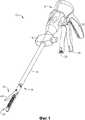
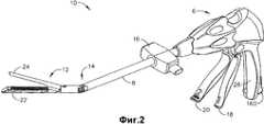
Фиг.1 и 2 - виды в перспективе хирургического отрезного и фиксирующего аппарата в соответствии с различными вариантами осуществления настоящего изобретения;1 and 2 are perspective views of a surgical cutting and fixing apparatus in accordance with various embodiments of the present invention;
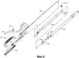
Фиг.3-5 - виды с пространственным разделением деталей концевого эффектора и стержня аппарата в соответствии с различными вариантами осуществления настоящего изобретения;Fig.3-5 are views with a spatial separation of the parts of the end effector and the rod apparatus in accordance with various variants of implementation of the present invention;
Фиг.6 - вид сбоку концевого эффектора в соответствии с различными вариантами осуществления настоящего изобретения;6 is a side view of an end effector in accordance with various embodiments of the present invention;
Фиг.7 - вид с пространственным разделением деталей рукоятки аппарата в соответствии с различными вариантами осуществления настоящего изобретения;7 is a view with a spatial separation of the parts of the handle of the apparatus in accordance with various variants of implementation of the present invention;
Фиг.8 и 9 - местные виды в перспективе рукоятки в соответствии с различными вариантами осуществления настоящего изобретения;Figs. 8 and 9 are perspective views of a handle in accordance with various embodiments of the present invention;
Фиг.10 - вид сбоку рукоятки в соответствии с различными вариантами осуществления настоящего изобретения;10 is a side view of a handle in accordance with various embodiments of the present invention;
Фиг.11 - схематическое изображение электрической схемы, применяемой в аппарате в соответствии с различными вариантами осуществления настоящего изобретения;11 is a schematic illustration of an electrical circuit used in an apparatus in accordance with various embodiments of the present invention;
Фиг.12-13 - виды сбоку рукоятки в соответствии с другими вариантами осуществления настоящего изобретения;12-13 are side views of a handle in accordance with other embodiments of the present invention;
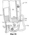
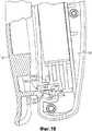
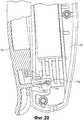
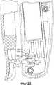
Фиг.14-22 - изображения различных механизмов для фиксации замыкающего рычага в соответствии с различными вариантами осуществления настоящего изобретения;Figures 14-22 are images of various mechanisms for locking the locking lever in accordance with various embodiments of the present invention;
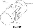
Фиг.23A-B - изображение универсального шарнира («u-шарнира»), который можно использовать в точке сочленения аппарата в соответствии с различными вариантами осуществления настоящего изобретения;23A-B is an image of a universal joint (“u-joint”) that can be used at the articulation point of the apparatus in accordance with various embodiments of the present invention;
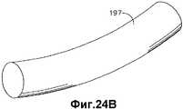
Фиг.24A-B - изображение торсионного троса, который можно использовать в точке сочленения аппарата в соответствии с различными вариантами осуществления настоящего изобретения;Figa-B - image of a torsion cable that can be used at the junction of the apparatus in accordance with various variants of implementation of the present invention;
Фиг.25-31 - изображение хирургического отрезного и фиксирующего аппарата с усилением в соответствии с другим вариантом осуществления настоящего изобретения;25-31 is an image of a surgical cutting and fixing apparatus with reinforcement in accordance with another embodiment of the present invention;
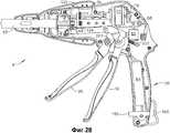
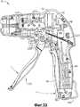
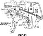
Фиг.32-36 - изображение хирургического отрезного и фиксирующего аппарата с усилением в соответствии с еще одним вариантом осуществления настоящего изобретения;32-36 is an image of a surgical cutting and fixing apparatus with reinforcement in accordance with another embodiment of the present invention;
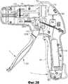
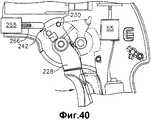
Фиг.37-40 - изображение хирургического отрезного и фиксирующего аппарата с тактильной обратной связью в соответствии с вариантами осуществления настоящего изобретения;Fig.37-40 - image of a surgical detachable and fixing apparatus with tactile feedback in accordance with the variants of implementation of the present invention;
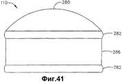
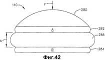
Фиг.41-42 - изображение пропорционального датчика, который можно использовать в соответствии с различными вариантами осуществления настоящего изобретения; иFigures 41-42 are an image of a proportional sensor that can be used in accordance with various embodiments of the present invention; and
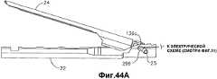
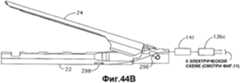
Фиг.43A-44C - изображение схем установки и конфигураций переключателей датчиков блокировок в цепях блокировок в соответствии с различными вариантами осуществления настоящего изобретения.Figa-44C is a depiction of installation diagrams and configurations of the switches of the sensors of the locks in the locking circuits in accordance with various variants of implementation of the present invention.
ПОДРОБНОЕ ОПИСАНИЕDETAILED DESCRIPTION
На фиг.1 и 2 изображен хирургический отрезной и фиксирующий аппарат 10 в соответствии с различными вариантами осуществления настоящего изобретения. Изображенный вариант осуществления представляет собой эндоскопический аппарат, и, в общем, описанные здесь варианты осуществления аппарата 10 являются эндоскопическими хирургическими отрезными и фиксирующими аппаратами. Следует отметить, однако, что, в соответствии с другими вариантами осуществления настоящего изобретения, аппарат может быть неэндоскопическим хирургическим отрезным и фиксирующим аппаратом, например лапароскопическим аппаратом.1 and 2, a surgical cutting and fixing
Хирургический аппарат 10, изображенный на фиг.1 и 2, содержит рукоятку 6, стержень 8 и шарнирно-поворотный концевой эффектор 12, шарнирно соединенный со стержнем 8 в шарнире 14 сочленения. Вблизи рукоятки 6 может быть обеспечено устройство 16 управления шарнирным поворотом для осуществления поворота концевого эффектора 12 на шарнире 14 сочленения. В показанном варианте осуществления концевой эффектор 12 выполнен с возможностью выполнения функции эндоскопического режущего инструмента для сжатия, отрезания и сшивания скобками ткани, хотя в других вариантах осуществления можно применять концевые эффекторы других типов, например концевые эффекторы для хирургических устройств других типов, например захваты, режущие приспособления, сшивающие скобками аппараты, приспособления для наложения зажимов, устройства доступа, устройства для доставки лекарства генной терапии к месту действия, ультразвуковые, RF- или лазерные устройства и т.п.The
Рукоятка 6 аппарата 10 может содержать замыкающий рычаг 18 и рычаг 20 прошивки для приведения в действие концевого эффектора 12. Специалистам в данной области техники очевидно, что аппараты, содержащие концевые эффекторы, предназначенные для разных хирургических целей, могут содержать разные количества или типы рычагов или других подходящих элементов управления для манипулирования концевым эффектором 12. Концевой эффектор 12 показан отделенным от рукоятки 6 предпочтительно удлиненным стержнем 8. В одном варианте осуществления врач или хирург, оперирующий аппаратом 10, может шарнирно поворачивать концевой эффектор 12 относительно стержня 8 с помощью устройства 16 управления шарнирным поворотом, как более подробно описано в находящейся на рассмотрении заявке на патент США № 11/329,020, «SURGICAL INSTRUMENT HAVING AN ARTICULATING END EFFECTOR», изобретателей Хьюэйля с соавторами (Hueil et al.), которая включена в настоящее описание путем отсылки.The
В настоящем примере концевой эффектор 12 содержит, помимо прочего, желоб 22 для скобок и зажимной элемент с поворотно-поступательным перемещением, например упор 24, которые удерживаются на некотором разделяющем их расстоянии, которое обеспечивает эффективное сшивание скобками и отрезание ткани, зажатой в концевом эффекторе 12. Рукоятка 6 содержит ручку 26 пистолетного типа, к которой замыкающий рычаг 18 подтягивается поворотным движением врачом для осуществления зажима или примыкания упора 24 к желобу 22 для скобок концевого эффектора 12, чтобы, тем самым, зажать ткань, расположенную между упором 24 и желобом 22. Рычаг 20 прошивки находится дальше снаружи от замыкающего рычага 18. После того как замыкающий рычаг 18 зафиксируется в положении примыкания, как дополнительно поясняется ниже, рычаг 20 прошивки может сделать небольшой поворот к ручке 26 пистолетного типа настолько, что его сможет достать оперирующий хирург, работающий одной рукой. Затем оперирующий хирург может подтянуть поворотным движением рычаг 20 прошивки к ручке 26 пистолетного типа для осуществления сшивания скобками и отрезания ткани, зажатой в концевом эффекторе 12. В других вариантах осуществления возможно применение зажимных элементов других типов, кроме упора 24, например, противостоящего зажима и т.п.In the present example, the
Далее следует понимать, что в настоящем описании термины «проксимальный» и «дистальный» применяют для обозначения положения относительно захвата практикующим врачом рукоятки 6 аппарата 10. Следовательно, концевой эффектор 12 является дистальным относительно более проксимальной рукоятки 6. Дополнительно следует понимать, что, для удобства и ясности, специальные термины, обозначающие пространственное положение, например «вертикальный» и «горизонтальный», использованы в настоящем описании применительно к чертежам. Однако существует множество пространственно-угловых положений применения хирургических аппаратов, и упомянутые термины не предполагают ограничительного и абсолютного значения.It should further be understood that in the present description, the terms “proximal” and “distal” are used to indicate the position relative to the grasp by the practitioner of the
Замыкающий рычаг 18 может быть приведен в действие первым. После того как врач удостоверится в удовлетворительном положении концевого эффектора 12, врач может подтянуть назад замыкающий рычаг 18 в его фиксируемое положение полного примыкания в непосредственной близости от ручки 26 пистолетного типа. Затем можно приводить в действие рычаг 20 прошивки. Рычаг 20 прошивки возвращается в разжатое положение (смотри фиг.1 и 2), когда врач прекращает нажатие, как более полно описано ниже. Деблокирующая кнопка на рукоятке 6, при нажатии, может отпустить зафиксированный замыкающий рычаг 18. Деблокирующая кнопка может иметь разные формы исполнения, например в виде сдвижной деблокирующей кнопки 160, показанной на фиг.14, и/или кнопки 172, показанной на фиг.16.The locking
На фиг.3 представлен вид с пространственным разделением деталей концевого эффектора 12 в соответствии с различными вариантами осуществления. Как показано в представленном варианте осуществления, концевой эффектор 12 может содержать, в дополнение к вышеупомянутым желобу 22 и упору 24, режущий инструмент 32, скользящий блок 33, кассету 34 для скобок, которая вмещена с возможностью извлечения в желоб 22, и винтовой шпиндель 36. Режущий инструмент 32 может представлять собой, например, нож. Упор 24 может быть поворотно-размыкаемым и смыкаемым вокруг оси 25 поворота, соединенной с проксимальным концом желоба 22. Упор 24 может также содержать лапку 27 на своем проксимальном конце, которая вставлена в компонент механической смыкающей системы (дополнительно описанной ниже) для размыкания и смыкания упора 24. Когда замыкающий рычаг 18 приводится в действие, то есть подтягивается пользователем аппарата 10, упор 24 может поворачиваться вокруг оси 25 поворота в сжатое или сомкнутое положение. Если зажатие концевым эффектором 12 является удовлетворительным, то оперирующий хирург может привести в действие рычаг 20 прошивки, который, как более подробно поясняется ниже, приводит нож 32 и скользящий блок 33 в продольное движение по желобу 22 с отрезанием, тем самым, ткани, зажатой внутри концевого эффектора 12. Перемещение скользящего блока 33 по желобу 22 вызывает выталкивание скобок (не показанных) из кассеты 34 для скобок сквозь отрезанную ткань к сомкнутому упору 24, который загибает скобки для фиксации отрезанной ткани. Патент США № 6,978,921, «SURGICAL STAPLING INSTRUMENT INCORPORATING AN E-BEAM FIRING MECHANISM», изобретателей Шелтона с соавторами (Shelton, IV et al.), который включен в настоящее описание путем отсылки, обеспечивает дополнительные сведения о такого рода двухходовых отрезных и сшивающих аппаратах. Скользящий блок 33 может быть составной частью кассеты 34, чтобы, когда нож 32 отводится после операции отрезания, скользящий блок 33 не отводился.Figure 3 presents a view with a spatial separation of the parts of the
Следует отметить, что, хотя в вариантах осуществления описанного здесь аппарата 10 применяется концевой эффектор 12, который сшивает скобками отрезанную ткань, в других вариантах осуществления возможно применение отличающихся методов фиксации или скрепления отрезанной ткани. Например, можно также применять концевые эффекторы, которые используют RF-энергию или клеи для фиксации отрезанной ткани. В патенте США № 5,709,680, «ELECTROSURGICAL HEMOSTATIC DEVICE», изобретателей Йейтса с соавторами (Yates et al.) и патенте США № 5,688,270, «ELECTROSURGICAL HEMOSTATIC DEVICE WITH RECESSED AND/OR OFFSET ELECTRODES», изобретателей Йейтса с соавторами (Yates et al.), которые включены в настоящее описание путем отсылки, предлагаются режущие инструменты, которые используют RF-энергию для скрепления отрезанной ткани. В заявке на патент США № 11/267,811, «SURGICAL STAPLING INSTRUMENTS STRUCTURED FOR DELIVERY OF MEDICAL AGENTS», изобретателей Джерома Р. Моргана с соавторами (Jerome R. Morgan, et al.) и заявке на патент США № 11/267,383, «SURGICAL STAPLING INSTRUMENTS STRUCTURED FOR PUMP-ASSISTED DELIVERY OF MEDICAL AGENTS», изобретателей Фредерика Е. Шелтона с соавторами (Frederick E. Shelton, IV, et al.), которые также включены в настоящее описание путем отсылки, предлагаются режущие инструменты, в которых применяются клеи для скрепления отрезанной ткани. Соответственно, хотя настоящее описание относится к операциям отрезания/сшивания скобками и подобным нижеследующим, следует понимать, что настоящий вариант осуществления является примерным и не предполагает ограничения. Возможно также использование других методов фиксации тканей.It should be noted that, although in the embodiments of the
На фиг.4 и 5 представлены виды с пространственным разделением деталей и на фиг.6 представлен вид сбоку концевого эффектора 12 и стержня 8 в соответствии с различными вариантами осуществления. Как показано в представленных вариантах осуществления, стержень 8 может содержать проксимальную замыкающую трубку 40 и дистальную замыкающую трубку 42, соединенные между собой с возможностью поворота поворотно-соединительными звеньями 44. Дистальная замыкающая трубка 42 содержит отверстие 45, в которое вставлена лапка 27 на упоре 24, для размыкания и смыкания упора 24, как дополнительно поясняется ниже. Внутри замыкающих трубок 40, 42 может быть расположена проксимальная несущая трубка 46. Внутри проксимальной несущей трубки 46 может быть расположен главный поворотный (или проксимальный) ведущий вал 48, который взаимодействует с вспомогательным (или дистальным) ведущим валом 50 через коническую зубчатую передачу 52. Вспомогательный ведущий вал 50 соединен с ведущим зубчатым колесом 54, которое находится в зацеплении с проксимальным ведущим зубчатым колесом 56 винтового шпинделя 36. Вертикальная коническая шестерня 52b может располагаться и поворачиваться в отверстии 57 в дистальном конце проксимальной несущей трубки 46. Можно применить дистальную несущую трубку 58 для вмещения вспомогательного ведущего вала 50 и ведущих зубчатых колес 54, 56. Главный ведущий вал 48, вспомогательный ведущий вал 50 и шарнирно-поворотный узел (например, коническая зубчатая передача 52a-c) иногда в настоящем описании совместно именуются «узлом главного ведущего вала».FIGS. 4 and 5 are exploded views, and FIG. 6 is a side view of an
Подшипник 38, расположенный на дистальном конце желоба 22 для скобок, вмещает винтовой шпиндель 36 и, тем самым, обеспечивает возможность свободного вращения винтового ведущего шпинделя 36 относительно желоба 22. Винтовой шпиндель 36 может сопрягаться с резьбовым отверстием (не показано) ножа 32 таким образом, что вращение шпинделя 36 вызывает поступательное перемещение ножа 32 в дистальном или проксимальном направлении (в зависимости от направления вращения) по желобу 22 для скобок. Соответственно, когда главный ведущий вал 48 приводится во вращение приведением в действие рычага 20 прошивки (как подробнее изложено ниже), коническая зубчатая передача 52a-c вынуждает вращаться вспомогательный ведущий вал 50, который, в свою очередь, благодаря зацеплению ведущих зубчатых колес 54, 56, приводит во вращение винтовой шпиндель 36, что вызывает продольное перемещение ведущего элемента 32 ножа по желобу 22 и, тем самым, отрезание любой ткани, зажатой внутри концевого эффектора. Скользящий блок 33 может быть выполнен, например, из пластика и может иметь скошенную дистальную поверхность. По мере того как скользящий блок 33 движется по желобу 22, скошенная передняя поверхность может выдвигать вверх или выталкивать скобки из кассеты 34 для скобок сквозь зажатую ткань к упору 24. Упор 24 загибает скобки и, тем самым, сшивает скобками отрезанную ткань. Когда нож 32 отводится, нож 32 и скользящий блок 33 могут расцепляться, при этом скользящий блок 33 остается на дистальном конце желоба 22.A bearing 38 located at the distal end of the
Вследствие отсутствия у пользователя обратной связи при операции отрезания/сшивания скобками аппараты с приводом от двигателя, в которых операция отрезания/сшивания скобками включается простым нажатием кнопки, не получили всеобщего признания врачами. Напротив, в вариантах осуществления настоящего изобретения эндоскопический режущий инструмент с приводом от двигателя обеспечивает пользователя обратной связью по срабатыванию, усилию и/или положению режущего инструмента в концевом эффекторе.Due to the lack of feedback from the user in the operation of cutting / stapling brackets, motor-driven devices in which the cutting / stapling operation of the brackets is turned on with a simple click of a button have not been universally recognized by doctors. In contrast, in embodiments of the present invention, an engine-driven endoscopic cutting tool provides the user with feedback on the actuation, force and / or position of the cutting tool in the end effector.
На фиг.7-10 представлен примерный вариант осуществления эндоскопического режущего инструмента с приводом от двигателя и, в частности, его рукоятки, в котором пользователь обеспечен обратной связью по срабатыванию и усилию нагрузки режущего инструмента в концевом эффекторе. Кроме того, данный вариант осуществления может использовать мощность, развиваемую пользователем при отведении назад рычага 20 прошивки, для подачи мощности в устройство (в так называемом «бустерном (с усилением)» режиме). Как показано в представленном варианте осуществления, рукоятка 6 содержит внешние нижние боковины 59, 60 и внешние верхние боковины 61, 62, которые собираются с образованием общего внешнего облика рукоятки 6. Батарейка 64, например ионная литиевая батарейка, может быть установлена в участок ручки 26 пистолетного типа рукоятки 6. Батарейка 64 питает электродвигатель 65, расположенный внутри верхнего участка, относящегося к участку ручки 26 пистолетного типа рукоятки 6. В соответствии с разными вариантами осуществления электродвигатель 65 может быть приводным щеточным электродвигателем постоянного тока с максимальной частотой вращения, приблизительно, 5000 об/мин. Электродвигатель 65 может приводить в движение 90°-ю коническую зубчатую передачу 66, содержащую первую коническую шестерню 68 и вторую коническую шестерню 70. Коническая зубчатая передача 66 может приводить в движение планетарную зубчатую передачу 72. Планетарная зубчатая передача 72 может содержать ведущую шестерню 74, соединенную с ведущим валом 76. Ведущая шестерня 74 может приводить в движение сопряженный зубчатый венец 78, который приводит в движение барабан 80 винтовой передачи посредством ведущего вала 82. Кольцо 84 может быть посажено на резьбе на барабан 80 винтовой передачи. Следовательно, когда электродвигатель 65 вращается, кольцо 84 приводится в движение по барабану 80 винтовой передачи посредством промежуточной конической зубчатой передачи 66, планетарной зубчатой передачи 72 и зубчатого венца 78.Figures 7-10 show an exemplary embodiment of an endoscopic cutting tool driven by an engine and, in particular, its handle, in which the user is provided with feedback on the response and load of the cutting tool in the end effector. In addition, this embodiment can use the power developed by the user when the
Рукоятка 6 может также содержать датчик 110 включения электродвигателя, связанный с рычагом 20 прошивки, для определения, когда рычаг 20 прошивки подтянут (или «прижат») к участку ручки 26 пистолетного типа рукоятки 6 оперирующим хирургом, и, тем самым, для запуска исполнения операции отрезания/сшивания скобками концевым эффектором 12. Датчик 110 может быть пропорциональным датчиком, например реостатом или переменным резистором. Когда рычаг 20 прошивки прижимают, датчик 110 определяет перемещение и передает электрический сигнал, характеризующий напряжение (или мощность) для подачи на электродвигатель 65. Когда датчик 110 является переменным резистором или чем-то подобным, частота вращения электродвигателя 65 может быть, в общем, пропорциональна величине перемещения рычага 20 прошивки. То есть если оперирующий хирург лишь немного подтягивает или прижимает рычаг 20 прошивки, то частота вращения электродвигателя 65 является относительно низкой. Когда рычаг 20 прошивки полностью подтянут (или находится в полностью прижатом положении), частота вращения электродвигателя 65 является максимальной. Другими словами, чем сильнее пользователь подтягивает рычаг 20 прошивки, тем более высокое напряжение подается на электродвигатель 65, что обуславливает более высокие частоты вращения.The
Рукоятка 6 может содержать среднюю деталь 104 рукоятки, прилегающую к верхнему участку рычага 20 прошивки. Рукоятка 6 может также содержать оттягивающую пружину 112, закрепленную между штырьками на средней детали 104 рукоятки и рычаге 20 прошивки. Оттягивающая пружина 112 может оттягивать рычаг 20 прошивки к его полностью разомкнутому положению. При этом когда оперирующий хирург отпустит рычаг 20 прошивки, оттягивающая пружина 112 оттянет рычаг 20 прошивки в его разомкнутое положение, что прекращает воздействие на датчик 110 и, тем самым, останавливает вращение электродвигателя 65. Более того, благодаря оттягивающей пружине 112, каждый раз, когда пользователь прижимает рычаг 20 прошивки, пользователь будет ощущать сопротивление операции прижима, что обеспечивает пользователя обратной связью по значению частоты вращения, развиваемой электродвигателем 65. Кроме того, оперирующий хирург может прекратить отведение назад рычага 20 прошивки для снятия, тем самым, усилия с датчика 110 и, тем самым, для останова электродвигателя 65. По существу, пользователь может остановить срабатывание концевого эффектора 12 с обеспечением, тем самым, оперирующего хирурга, в какой-то степени, возможностью управления операцией отрезания/фиксации.The
Дистальный конец барабана 80 винтовой передачи содержит дистальный ведущий вал 120, который приводит в движение зубчатый венец 122, который сопрягается с ведущей шестерней 124. Ведущая шестерня 124 соединена с главным ведущим валом 48 узла главного ведущего вала. При этом вращение электродвигателя 65 вызывает вращение узла главного ведущего вала, что приводит в действие концевой эффектор 12 вышеописанным способом.The distal end of the
Кольцо 84, посаженное на резьбе на барабан 80 винтовой передачи, может содержать штырек 86, который расположен внутри прорези 88 в прорезанной кулисе 90. Прорезанная кулиса 90 содержит отверстие 92 на противоположном конце 94, которое вмещает шарнирный палец 96, который присоединен между внешними боковинами 59, 60 рукоятки. Шарнирный палец 96 расположен также с проходом через отверстие 100 в рычаге 20 прошивки и отверстие 102 в средней детали 104 рукоятки.The
Кроме того, рукоятка 6 может содержать датчик 130 реверса электродвигателя (или конца хода) и датчик 142 останова электродвигателя (или начала хода). В различных вариантах осуществления датчик 130 реверса электродвигателя может быть концевым переключателем, расположенным на дистальном конце барабана 80 винтовой передачи, так что кольцо 84, установленное на резьбе на барабане 80 винтовой передачи, входит в контакт с датчиком 130 реверса электродвигателя и включает его, когда кольцо 84 достигает дистального конца барабана 80 винтовой передачи. Датчик 130 реверса электродвигателя, при включении, посылает в электродвигатель 65 сигнал на реверсирование направления его вращения и, тем самым, на отведение ножа 32 концевого эффектора 12 по окончании операции отрезания.In addition, the
Датчик 142 останова электродвигателя может быть, например, нормально замкнутым концевым переключателем. В различных вариантах осуществления упомянутый датчик может располагаться на проксимальном конце барабана 80 винтовой передачи, чтобы кольцо 84 размыкало датчик 142, когда кольцо 84 достигнет проксимального конца барабана 80 винтовой передачи.The
Во время работы, когда хирург, оперирующий аппаратом 10, подтягивает назад рычаг 20 прошивки, датчик 110 определяет расположение рычага 20 прошивки и посылает сигнал в электродвигатель 65 для включения переднего вращения электродвигателя 65 с частотой, например, пропорциональной тому, насколько сильно оперирующий хирург подтягивает рычаг 20 прошивки. Переднее вращение электродвигателя 65, в свою очередь, обуславливает вращение зубчатого венца 78 на дистальном конце планетарной зубчатой передачи 72 и, тем самым, приводит во вращение барабан 80 винтовой передачи, что вызывает движение кольца 84, установленного на резьбе на барабане 80 винтовой передачи, в дистальном направлении по барабану 80 винтовой передачи. Вращение барабана 80 винтовой передачи приводит во вращение также вышеописанный узел главного ведущего вала, что, в свою очередь, вызывает срабатывание ножа 32 в концевом эффекторе 12. То есть нож 32 и скользящий блок 33 приводятся в продольное движение по желобу 22 с отрезанием, тем самым, ткани, зажатой в концевом эффекторе 12. Кроме того, вынуждается выполнение операции сшивания скобками концевым эффектором 12 в тех вариантах осуществления, в которых применяется сшивающий скобками концевой эффектор.During operation, when the surgeon operating the
К моменту когда операция отрезания/сшивания скобками концевым эффектором 12 будет закончена, кольцо 84 на барабане 80 винтовой передачи продвинется до дистального конца барабана 80 винтовой передачи и, тем самым, вызовет включение датчика 130 реверса электродвигателя, который посылает сигнал в электродвигатель 65 для осуществления реверсирования вращения электродвигателя 65. Это, в свою очередь, вызывает отведение ножа 32, а также приводит кольцо 84 на барабане 80 винтовой передачи в обратное движение к проксимальному концу барабана 80 винтовой передачи.By the time the cutting / stapling operation of the brackets by the
Средняя деталь 104 рукоятки имеет задний заплечик 106, который входит в зацепление с прорезанной кулисой 90, как лучше всего показано на фиг.8 и 9. Средняя деталь 104 рукоятки имеет также передний упор 107 перемещения, который входит в зацепление с рычагом 20 прошивки. Перемещение прорезанной кулисы 90 регулируется, как поясняется выше, вращением электродвигателя 65. Когда прорезанная кулиса 90 поворачивается против часовой стрелки (CCW) в то время как кольцо 84 движется от проксимального конца барабана 80 винтовой передачи к дистальному концу, средняя деталь 104 рукоятки будет иметь свободу поворота против часовой стрелки. Следовательно, по мере того как пользователь будет прижимать рычаг 20 прошивки, рычаг 20 прошивки будет входить в зацепление с передним упором 107 перемещения средней детали 104 рукоятки и, тем самым, вынуждать среднюю деталь 104 рукоятки вращаться против часовой стрелки. Однако вследствие зацепления заднего заплечика 106 с прорезанной кулисой 90, средняя деталь 104 рукоятки сможет поворачиваться против часовой стрелки лишь настолько, насколько допускает прорезанная кулиса 90. При этом если электродвигатель 65 должен перестать вращаться по какой-либо причине, то прорезанная кулиса 90 перестанет поворачиваться, и пользователь не сможет дальше прижимать рычаг 20 прошивки, так как средняя деталь 104 рукоятки не будет свободно поворачиваться против часовой стрелки из-за прорезанной кулисы 90.The
На фиг.41 и 42 представлено изображение двух состояний датчика переменной величины, который можно использовать в качестве датчика 110 включения электродвигателя в соответствии с различными вариантами осуществления настоящего изобретения. Датчик 110 может содержать лобовой участок 280, первый электрод (A) 282, второй электрод (B) 284 и сжимаемый диэлектрический материал 286 (например, EAP (электроактивный полимер)) между электродами 282, 284. Датчик 110 может быть расположен так, что лобовой участок 280 контактирует с рычагом 20 прошивки при его отведении назад. Соответственно, когда рычаг 20 прошивки отводят назад, диэлектрический материал 286 сжимается, как показано на фиг.42, так что электроды 282, 284 сближаются. Поскольку расстояние «b» между электродами 282, 284 находится в прямой связи с полным сопротивлением между электродами 282, 284, то чем больше расстояние, тем больше полное сопротивление, и чем короче расстояние, тем меньше полное сопротивление. При этом величина усилия сжатия диэлектрика 286 из-за отведения назад рычага 20 прошивки (обозначенного как усилие «F» на фиг.42) пропорциональна полному сопротивлению между электродами 282, 284, которое можно использовать для пропорционального управления электродвигателем 65.On Fig and 42 presents an image of two states of a variable sensor that can be used as a
Компоненты примерной смыкающей системы для смыкания (или сжатия) упора 24 концевого эффектора 12 посредством отведения назад замыкающего рычага 18 также показаны на фиг.7-10. В представленном варианте осуществления смыкающая система содержит вилку 250, соединенную с замыкающим рычагом 18 с помощью пальца 251, который вставлен сквозь совмещенные отверстия как в замыкающем рычаге 18, так и в вилке 250. Шарнирный палец 252, на котором поворачивается замыкающий рычаг 18, вставлен сквозь другое отверстие в замыкающем рычаге 18, которое смещено от места, где палец 251 вставлен сквозь замыкающий рычаг 18. Следовательно, отведение назад замыкающего рычага 18 вынуждает верхнюю часть замыкающего рычага 18, к которой вилка 250 прикреплена пальцем 251, поворачиваться против часовой стрелки. Дистальный конец вилки 250 соединен пальцем 254 с первой замыкающей скобой 256. Первая замыкающая скоба 256 соединяется со второй замыкающей скобой 258. Замыкающие скобы 256, 258 вместе образуют отверстие, в которое посажен и зафиксирован проксимальный конец проксимальной замыкающей трубки 40 (смотри фиг.4) так, что продольное перемещение замыкающих скоб 256, 258 вызывает продольное перемещение проксимальной замыкающей трубки 40. Аппарат 10 содержит также замыкающий шток 260, находящийся внутри проксимальной замыкающей трубки 40. Замыкающий шток 260 может содержать проем 261, в который входит стойка 263 одной из внешних деталей рукоятки, например внешней нижней боковины 59 в показанном варианте осуществления, для жесткого соединения замыкающего штока 260 с рукояткой 6. При этом проксимальная замыкающая трубка 40 может продольно перемещаться относительно замыкающего штока 260. Замыкающий шток 260 может также содержать дистальный кольцевой выступ 267, который входит в проточку 269 в проксимальной несущей трубке 46 и фиксируется в данной проточке крышкой 271 (смотри фиг.4).The components of an exemplary locking system for locking (or compressing) the
Когда в процессе работы вилка 250 поворачивается из-за перемещения назад замыкающего рычага 18, замыкающие скобы 256, 258 вынуждают проксимальную замыкающую трубку 40 перемещаться в дистальном направлении (т.е. от конца рукоятки 6 аппарата 10), что вызывает перемещение дистальной замыкающей трубки 42 в дистальном направлении, что, в свою очередь, вызывает поворот упора 24 вокруг оси 25 поворота в зажатое или сомкнутое положение. Когда замыкающий рычаг 18 деблокируется из положения фиксации, проксимальная замыкающая трубка 40 принуждается к сдвигу в проксимальном направлении, что приводит к сдвигу дистальной замыкающей трубки 42 в проксимальном направлении, что, в свою очередь, благодаря лапке 27, вставленной в отверстие 45 дистальной замыкающей трубки 42, вызывает поворот упора 24 вокруг оси 25 поворота в разомкнутое или несжатое положение. При этом, путем отведения назад и фиксации замыкающего рычага 18, оперирующий хирург может зажать ткань между упором 24 и желобом 22 и может разжать ткань после операции отрезания/сшивания скобками путем деблокирования замыкающего рычага 18 из положения фиксации.When the
На фиг.11 представлена принципиальная схема электрической цепи аппарата 10 в соответствии с различными вариантами осуществления настоящего изобретения. Когда оперирующий хирург первоначально подтягивает рычаг 20 прошивки после фиксации замыкающего рычага 18, датчик 110 включается и допускает протекание через него тока. Если нормально разомкнутый переключатель датчика 130 реверса электродвигателя находится в разомкнутом состоянии (что означает, что конец хода концевого эффектора еще не достигнут), ток будет протекать к однополюсному двухпозиционному реле 132. Поскольку переключатель датчика 130 реверса электродвигателя не замкнут, то катушка 134 индуктивности реле 132 не будет возбуждена, и поэтому реле 132 будет находиться в своем невозбужденном состоянии. Электрическая схема дополнительно содержит переключатели 136a-d датчиков блокировок, совместно образующих цепь 137 блокировки, через которую должен протекать ток от реле 132, когда на последнем нет напряжения, для включения питания и запуска в работу электродвигателя 65. Каждый переключатель 136a-d датчика блокировки выполнен с возможностью сохранения разомкнутого (т.е. непроводящего) состояния переключения или замкнутого (т.е. проводящего) состояния переключения, в зависимости от, соответственно, наличия или отсутствия соответствующего условия. Любое из соответствующих условий, при его наличии, когда аппарат 10 приводят в действие, может стать причиной неудовлетворительного исполнения операции отрезания и сшивания скобками и/или повреждения аппарата 10. Условия, на которые могут реагировать переключатели 136a-d датчиков блокировок, включают в себя, например, отсутствие кассеты 34 для скобок в желобе 22, присутствие израсходованной (например, ранее отработанной) кассеты 34 для скобок в желобе 22 и разомкнутое (или, в ином случае, недостаточно сомкнутое) положение упора 24 относительно желоба 22. Другие условия, на которые могут реагировать переключатели 136a-d датчиков блокировок, например износ компонента, можно выводить по суммарному количеству операций прошивки/отрезания, произведенных аппаратом 10. Соответственно, если имеет место любое из упомянутых условий, то соответствующие переключатели 136a-d датчиков блокировок сохраняют разомкнутое состояние переключения и, тем самым, предотвращают протекание тока, необходимого для включения в работу электродвигателя 65. Пропускание тока датчиками 136a-d блокировки допускается только после того, как устранены все условия. Специалистам будет очевидно, что вышеописанные условия приведены только для примера и что можно обеспечить дополнительные переключатели датчиков блокировки для реакции на другие условия, вредные для работы аппарата 10. Аналогичным образом очевидно, что в вариантах осуществления, в которых, по меньшей мере, одно вышеописанное условие может отсутствовать или не имеет значения, число переключателей датчиков блокировки меньше, чем описано.11 is a circuit diagram of an electrical circuit of
Как показано на фиг.11, переключатель 136a датчика блокировки может быть реализован с использованием конфигурации нормально разомкнутого переключателя, так что замкнутое состояние переключения сохраняется, когда кассета 34 для скобок находится в положении, соответствующем ее правильному размещению в желобе 22. Когда кассета 34 для скобок не установлена в желоб 22 или установлена неправильно (например, с нарушением совмещения), переключатель 136a датчика блокировки сохраняет разомкнутое состояние переключения.As shown in FIG. 11, the
Переключатель 136b датчика блокировки может быть реализован с использованием конфигурации нормально разомкнутого переключателя, так что замкнутое состояние переключения сохраняется только в том случае, когда в желобе 22 присутствует неизрасходованная кассета 34 для скобок (т.е. кассета 34 для скобок со скользящим блоком 33 в положении, не приводимом в действие). Присутствие израсходованной кассеты 34 для скобок в желобе 22 вынуждает переключатель 136b датчика блокировки оставаться в разомкнутом состоянии переключения.The
Переключатель 136c датчика блокировки может быть реализован с использованием конфигурации нормально разомкнутого переключателя, так что замкнутое состояние переключения сохраняется, когда упор 24 находится в сомкнутом положении относительно желоба 22. Как дополнительно подробнее изложено ниже, управление переключателем 136c датчика блокировки возможно в соответствии с параметром временной задержки, при этом замкнутое состояние переключения выдерживается только после того, как упор 24 находится в сомкнутом положении в течение заданного периода времени.The
Переключатель 136d датчика блокировки может быть реализован с использованием конфигурации нормально замкнутого переключателя, так что замкнутое состояние переключения сохраняется только в том случае, когда суммарное число операций прошивки/отрезания, произведенных аппаратом 10, меньше заданного числа. Как дополнительно подробнее изложено ниже, переключатель 136d датчика блокировки может быть связан со счетным устройством 304, выполненным с возможностью ведения счета, характеризующего суммарное число операций прошивки/отрезания, произведенных аппаратом 10, сравнения сосчитанного числа с заданным числом и управления состоянием переключения переключателя 136d датчика блокировки по результатам сравнения.The
В соответствии с различными вариантами осуществления цепь 137 блокировки может содержать, по меньшей мере, один индикатор, доступный для наблюдения пользователем аппарата 10, для отображения состояния, по меньшей мере, одного из переключателей 136a-d датчиков блокировок. Как показано на фиг.11, например, каждый переключатель 136a-d датчика блокировки может содержать зеленый LED (светоизлучающий диод) 139a и красный LED 139b, относящиеся к переключателю. Цепь 137 блокировки может быть собрана так, что LED 139a,b возбуждаются, когда соответствующий переключатель 136a-d датчика блокировки выдерживается, соответственно, в замкнутом и разомкнутом состояниях блокировки. Следует понимать, что переключатели 136a-d датчиков блокировок могут содержать, по меньшей мере, один вспомогательный переключающий контакт (не показанный), обладающий переключающей конфигурацией, пригодной для управления LED 139a,b вышеописанным способом.In accordance with various embodiments, the
На фиг.43A-44C показаны схемы установки и конфигурации переключателей 136a-d датчиков блокировок в цепи 137 блокировки в соответствии с различными вариантами осуществления настоящего изобретения. Как показано на фиг.43A, переключатель 136a датчика блокировки может содержать первый переключающий контакт 288a и второй переключающий контакт 288b, расположенные на внутренней стенке желоба 22 и электрически изолированные от него. Первый и второй переключающие контакты 288a,b занимают, соответственно, такие положения, что, когда кассета 34 для скобок находится в положении, соответствующем ее правильному размещению в желобе 22, проводящий или полупроводящий участок 290 кассеты 34 для скобок (представленный, в качестве примера, металлическим участком лотка кассеты 34 для скобок) контактирует с первым и вторым переключающими контактами 288a,b с образованием проводящего пути между ними. Как лучше всего показано на фиг.43B, каждый переключающий контакт 288a,b может включать в себя скругленный контур для сведения к минимуму механического сопротивления кассете 34 для скобок, при ее вмещении в желоб 22 и для создания возможности надежного электрического контакта с проводящим участком 290 кассеты. Следовательно, проводящий участок 290 выполняет функцию сохранения переключателя 136a датчика блокировки в замкнутом состоянии переключения. Хотя переключающие контакты 288a,b изображены расположенными рядом на участке боковой стенки желоба 22, следует понимать, что каждый переключающий контакт 288a,b может, в общем случае, располагаться в любом месте внутри желоба 22, в котором возможен подходящий электрический контакт с проводящим элементом 290. Кроме того, следует понимать, что переключатель 136a датчика блокировки может быть, в альтернативном варианте, реализован с использованием традиционного контактного концевого переключателя. В соответствии с такими вариантами осуществления концевой переключатель может быть расположен так, что кассета 34 для скобок, при установке в желоб 22, механически приводит в действие концевой переключатель так, что поддерживается замкнутое состояние переключения. Следует также понимать, что переключатель 136a датчика блокировки также может быть реализован с использованием традиционного неконтактного концевого переключателя, например концевого магнитного герконового реле или бесконтактного переключателя на эффекте Холла. В соответствии с такими вариантами осуществления кассета 34 для скобок может содержать магнит, пригодный, чтобы обеспечивать сохранение переключателем 136a датчика блокировки замкнутого состояния переключения, когда кассета 34 для скобок установлена.On figa-44C shows the installation diagrams and configurations of the
Как лучше всего показано на фиг.43B, переключатель 136b датчика блокировки может быть смонтирован на внутренней нижней поверхности желоба 22. В соответствии с различными вариантами осуществления и, как показано, переключатель 136b датчика блокировки может быть реализован с использованием контактного концевого переключателя традиционной конструкции, которая пригодна для обнаружения линейного перемещения. Переключатель 136b датчика блокировки может иметь такую ориентацию, что его приводимый в действие участок продолжается вверх от нижней внутренней поверхности желоба 22. Переключатель 136b датчика блокировки может быть расположен на нижней поверхности желоба 22 так, что, когда установлена неизрасходованная кассета 34 для скобок, нижний участок скользящего блока 33 механически приводит в действие переключатель 136b датчика блокировки и обеспечивает, тем самым, сохранение замкнутого состояния переключения. Соответственно, присутствие неизрасходованной кассеты 34 для скобок (т.е. кассеты для скобок со скользящим блоком 33 в неотработанном положении) допускает протекание тока через переключатель 136b датчика блокировки. Следует понимать, что переключатель 136b датчика блокировки может быть реализован иначе, с использованием традиционного неконтактного переключателя (например, концевого магнитного герконового реле или бесконтактного переключателя на эффекте Холла). При исполнении такими методами скользящий блок 33 может содержать, например, намагниченный участок, который приводит в действие переключатель 136b датчика блокировки, когда скользящий блок 33 находится в неотработанном положении.As best shown in FIG. 43B, the
Как показано на фиг.44A, переключатель 136c датчика блокировки расположен вблизи дистального конца одного из шарнирных отверстий 296, образованных на проксимальном конце желоба 22 для зацепления с осью 25 поворота упора 24. В соответствии с различными вариантами осуществления и, как показано, переключатель 136c датчика блокировки может быть реализован с использованием контактного концевого переключателя традиционной конструкции, которая пригодна для обнаружения линейного перемещения. Однако следует понимать, что взамен упомянутого переключателя можно применить неконтактный концевой переключатель. Переключатель 136c датчика блокировки может иметь такую ориентацию, что его приводимый в действие участок продолжается немного выше дистального конца соответствующего шарнирного отверстия 296. Когда упор 24 находится в разомкнутом положении относительно желоба 22 (как показано на фиг.44A), ось поворота 25 расположена на проксимальном конце шарнирного отверстия 296. Смыкание упора 24 приводит к перемещению оси 25 поворота к дистальному концу шарнирного отверстия 296. Происходящий в результате контакт оси 25 поворота с приводимым в действие участком переключателя 136c датчика блокировки вынуждает переключатель 136c датчика блокировки сохранять замкнутое состояние переключения и, следовательно, допускать протекание через него тока.As shown in FIG. 44A, the
В соответствии с другими вариантами осуществления и, как показано на фиг.44B, переключатель 136c датчика блокировки может быть выполнен иначе, с возможностью сохранения замкнутого состояния переключения в зависимости от электрического сигнала. Электрический сигнал может быть, например, аналоговым сигналом, который вырабатывается датчиком 298 усилия, расположенным на нижней внутренней поверхности желоба 22, и который представляет величину сжимающего усилия, прилагаемого упором 24. Таким образом, можно сделать вывод о сомкнутом положении упора 24, если аналоговый сигнал имеет достаточно большую амплитуду. Соответственно, аналоговый сигнал может приниматься компаратором 141, выполненным с возможностью определения, превосходит ли амплитуда заданный порог, записанный в памяти компаратора. Если порог превышен, что означает смыкание упора 24, компаратор 141 вынуждает переключатель 136c датчика блокировки сохранять замкнутое состояние переключения и, следовательно, допускать протекание через него тока. Если амплитуда аналогового сигнала ниже заданного порога, что означает, что упор 24 сомкнут недостаточно, то компаратор 141 вынуждает переключатель 136c датчика блокировки сохранять разомкнутое состояние переключения и, следовательно, не допускать протекания через него тока. Следует понимать, что хотя компаратор 141 показан отдельно, он может составлять одно целое с переключателем 136c датчика блокировки для формирования общего устройства. Кроме того, следует понимать, что заданный порог, хранящийся в памяти компаратора 141, можно регулировать, при необходимости, для отражения усилия, характеризующего смыкание упора 24 при разных операциях отрезания и сшивания скобками.In accordance with other embodiments and, as shown in FIG. 44B, the
В некоторых случаях может быть необходимо или, в других отношениях, желательно задерживать начало операции прошивки/отрезания на некоторый период времени после смыкания упора 24. Например, введение задержки между операциями сжатия и прошивки/отрезания может служить улучшению стабилизации сжатой ткани. Соответственно, как показано на фиг.44C, варианты осуществления настоящего изобретения могут содержать таймер 300, предварительно настроенный на временную задержку (например, 12-секундную) и выполненный с возможностью управления состоянием переключения переключателя 136c датчика блокировки в соответствии с контролируемым по времени положением упора 24. Следует понимать, что хотя таймер 300 показан отдельно, он может составлять одно целое с переключателем 136c датчика блокировки для формирования общего устройства (например, реле времени). В предпочтительном варианте таймер 300 реализован в виде электронного устройства, хотя следует понимать, что вместо него возможно применение механического таймера. Нормально разомкнутый концевой переключатель 302, выполненный идентично переключателю, показанному на фиг.44A, может быть соединен с таймером 300 таким образом, что отсчет времени начинается, когда упор 24 находится в сомкнутом положении относительно желоба 22. По истечении предварительно настроенной временной задержки таймер 300 вынуждает переключатель 136c датчика блокировки сохранять замкнутое состояние переключения и, следовательно, допускать протекание через него тока. Таймер 300 может быть сброшен в ответ на переход концевого переключателя 302 в разомкнутое состояние переключения (т.е., когда упор 24 находится в разомкнутом положении). Следует понимать, что предварительно настроенную временную задержку таймера 300 можно настраивать избирательно (например, с использованием регулировки встроенного потенциометра), согласно требованию.In some cases, it may be necessary or, in other respects, it is desirable to delay the start of the flashing / cutting operation for a certain period of time after closing the
Как также показано на фиг.11, электрическая схема может содержать счетное устройство 304, выполненное с возможностью ведения счета, характеризующего суммарное число операций прошивки/отрезания, произведенных аппаратом 10, и, с учетом сосчитанного числа, управления состоянием переключения переключателя 136d датчика блокировки. Следует понимать, что хотя счетное устройство 304 показано отдельно, оно может составлять одно целое с переключателем 136d датчика блокировки для формирования общего устройства. В предпочтительном варианте счетное устройство 304 реализовано в виде электронного устройства, имеющего вход для наращивания сосчитанного числа по изменению дискретного электрического сигнала, подаваемого в данное устройство. Следует понимать, что, вместо вышеупомянутого варианта, можно применить механический счетчик, выполненный с возможностью ведения счета на основе механического входного сигнала (например, отведения назад рычага 20 прошивки). При реализации в виде электронного устройства любой дискретный сигнал, присутствующий в электрической схеме, который изменяется один раз при каждой операции прошивки/отрезания, можно использовать в качестве входного сигнала счетного устройства 304. Как показано на фиг.11, например, можно использовать дискретный электрический сигнал, получающийся в результате срабатывания датчика 130 конца хода. Счетное устройство 304 может управлять состоянием переключения переключателя 136d датчика блокировки таким образом, что замкнутое состояние переключения сохраняется, когда сосчитанное число меньше заданного числа, записанного в памяти счетного устройства 304. Когда сосчитанное число равно заданному числу, счетное устройство 304 вынуждает переключатель 136d датчика блокировки сохранять разомкнутое состояние переключения и, следовательно, не допускать протекание через него тока. Следует понимать, что заданное число, записанное в памяти счетного устройства 304, можно настраивать избирательно, согласно требованию. В соответствии с различными вариантами осуществления счетное устройство 304 может быть связано с дисплеем 305, например жидкокристаллическим (LCD) дисплеем, составляющим одно целое с аппаратом 10, для отображения для пользователя либо сосчитанного числа, либо разность между заданным числом и сосчитанным числом.As also shown in FIG. 11, the circuitry may include a
Когда переключатели 136a-d датчиков блокировок совместно сохраняют замкнутое состояние переключения, однополюсное однопозиционное реле 138 находится под напряжением. Когда реле 138 находится под напряжением, ток протекает через реле 138, через датчик 110 на переменном резисторе и, при посредстве двухполюсного двухпозиционного реле 140, через электродвигатель 65 и, тем самым, питает электродвигатель 65 и обеспечивает его вращение в переднем направлении. Поскольку выходной сигнал реле 138, после подачи на него напряжения, поддерживает реле 138 в возбужденном состоянии, пока под напряжением находится реле 132, то цепь 137 блокировки не будет выполнять функцию предотвращения действия электродвигателя 165 после его включения, даже если, по меньшей мере, один из переключателей 136a-d датчиков блокировок впоследствии сохраняет разомкнутое состояние переключения. Однако, в других вариантах осуществления, может быть необходимо или, в других отношениях, желательно соединить цепь 137 блокировки и реле 138 так, что, по меньшей мере, один из переключателей 136a-d датчиков блокировок должен сохранять замкнутое состояние переключения, чтобы поддерживать работу электродвигателя 165 после его включения.When the
Вращение электродвигателя в переднем направлении вынуждает кольцо 84 перемещаться в дистальном направлении и, тем самым, выключать переключатель датчика 142 останова электродвигателя. Так как переключатель датчика 142 является нормально замкнутым, электромагнит 306 находится под напряжением. Электромагнит 306 может быть обычным нажимным соленоидом, который, под напряжением, вызывает аксиальное выдвижение сердечника (не показанного). Как поясняется ниже в связи с фиг.14-22, выдвижение сердечника может выполнять функцию фиксации замыкающего рычага 18 в отведенном назад положении, с предотвращением, тем самым, размыкания упора 24 в то время, когда выполняется операция прошивки/отрезания (т.е. в то время, когда переключатель датчика 142 не включен). После обесточивания электромагнита 306 сердечник отводится назад, так что возможно ручное отпускание замыкающего рычага 18.Rotating the motor in the forward direction causes the
Когда концевой эффектор 12 достигнет конца своего хода, датчик 130 реверса электродвигателя включится, и, тем самым, переключатель датчика 130 замкнется, и реле 132 получит питание. В результате этого реле 132 переключается в его возбужденное состояние (не показанное на фиг.11), что приводит к протеканию тока в обход цепи 137 блокировки и переменного резистора 110 и, вместо этого, вынуждает ток протекать как через нормально замкнутое двухполюсное двухпозиционное реле 140, так и обратно через электродвигатель 65, но, благодаря реле 140, таким образом, что вызывает реверс направления вращения электродвигателя 65.When the
Поскольку переключатель датчика 142 останова электродвигателя является нормально замкнутым, ток будет протекать обратно через реле 132 с удерживанием его под напряжением, пока переключатель датчика 142 не разомкнется. Когда нож 32 полностью отводится, переключатель датчика 142 останова электродвигателя срабатывает и, тем самым, вызывает размыкание переключателя датчика 142, с выключением, тем самым, питания электродвигателя 65 и снятием напряжения с соленоида 306.Since the switch of the
В других вариантах осуществления вместо пропорционального датчика 110 можно применить двоичный датчик. В таких вариантах осуществления частота вращения электродвигателя 65 не будет пропорциональной усилию, прилагаемому оперирующим хирургом. Вместо этого электродвигатель 65 вращался бы обычно с постоянной частотой. Но оперирующий хирург продолжал бы ощущать обратную связь по усилию, так как рычаг 20 прошивки включен в цепь зубчатых передач привода.In other embodiments, a binary sensor may be used instead of the
На фиг.12 представлен вид сбоку рукоятки 6 механизированного эндоскопического режущего инструмента с усилением в соответствии с другим вариантом осуществления. Вариант осуществления на фиг.12 аналогичен варианту осуществления на фиг.7-10, за исключением того, что в варианте осуществления на фиг.12 отсутствует прорезанная кулиса, соединенная с кольцом 84, установленным на резьбе на барабан 80 винтовой передачи. Вместо этого в варианте осуществления на фиг.12 кольцо 84 содержит участок 114 датчиков, который перемещается с кольцом 84 по мере того, как кольцо 84 движется в дистальном направлении (и обратно) по барабану 80 винтовой передачи. Участок 114 датчиков содержит вырез 116. Датчик 130 реверса электродвигателя может находиться на дистальном конце выреза 116, и датчик 142 останова электродвигателя может находиться на проксимальном конце выреза 116. Когда кольцо 84 перемещается в дистальном направлении (и обратно) по барабану 80 винтовой передачи, участок 114 датчиков перемещается вместе с ним. Кроме того, как показано на фиг.12, средняя деталь 104 может иметь кулису 118, которая продолжается в вырез 116.On Fig presents a side view of the
Во время работы, когда хирург, оперирующий аппаратом 10, отводит рычаг 20 прошивки назад к ручке 26 пистолетного типа, датчик 110 включения электродвигателя определяет движение и посылает сигнал включения питания электродвигателю 65, который, помимо прочего, приводит во вращение барабан 80 винтовой передачи. В то время, когда барабан 80 винтовой передачи вращается, кольцо 84, установленное на резьбе на барабане 80 винтовой передачи, продвигается вперед (или отводится назад, в зависимости от направления вращения). Кроме того, вследствие подтягивания рычага 20 прошивки, средняя деталь 104 принуждается к повороту против часовой стрелки вместе с рычагом 20 прошивки благодаря переднему упору 107 перемещения, который находится в зацеплении с рычагом 20 прошивки. Поворот средней детали 104 против часовой стрелки вынуждает кулису 118 поворачиваться против часовой стрелки с участком 114 датчиков кольца 84, так что кулиса 118 остается расположенной в вырезе 116. Когда кольцо 84 достигает дистального конца барабана 80 винтовой передачи, кулиса 118 войдет в контакт с датчиком 130 реверса электродвигателя и, тем самым, вызовет срабатывание этого датчика. Аналогично, когда кольцо 84 достигает проксимального конца барабана 80 винтовой передачи, кулиса 118 войдет в контакт с датчиком 142 останова электродвигателя и, тем самым, вызовет срабатывание этого датчика. Описанные действия могут, соответственно, реверсировать и останавливать электродвигатель 65, как изложено выше.During operation, when the surgeon operating the
На фиг.13 представлен вид сбоку рукоятки 6 механизированного эндоскопического режущего инструмента с усилением в соответствии с другим вариантом осуществления. Вариант осуществления на фиг.13 аналогичен варианту осуществления на фиг.7-10, за исключением того, что в варианте осуществления на фиг.13 отсутствует прорезь в кулисе 90. Вместо этого кольцо 84, установленное на резьбе на барабане 80 винтовой передачи, содержит вертикальный паз 126. Вместо прорези кулиса 90 содержит штырек 128, который расположен в пазу 126. Когда барабан 80 винтовой передачи вращается, кольцо 84, посаженное на резьбе на барабан 80 винтовой передачи, продвигается вперед (или отводится назад, в зависимости от направления вращения). Кулиса 90 поворачивается против часовой стрелки по мере того, как кольцо 84 продвигается вперед, благодаря штырьку 128, расположенному в пазу 126, как показано на фиг.13.On Fig presents a side view of the
Как упоминалось выше, при применении двухходового механизированного аппарата, оперирующий хирург сначала подтягивает назад и фиксирует замыкающий рычаг 18. На фиг.14 и 15 представлен один вариант осуществления метода фиксации замыкающего рычага 18 к участку ручки 26 пистолетного типа рукоятки 6. В изображенном варианте осуществления участок ручки 26 пистолетного типа содержит зацеп 150, который поджат в поворот против часовой стрелки на оси 151 поворота торсионной пружиной 152. Кроме того, замыкающий рычаг 18 содержит замыкающую перекладину 154. По мере того как оперирующий хирург подтягивает замыкающий рычаг 18, замыкающая перекладина 154 входит в контакт со скошенным участком 156 зацепа 150 и, тем самым, поворачивает зацеп 150 вверх (или по часовой стрелке на фиг.14-15), пока замыкающая перекладина 154 не пройдет полностью скошенный участок 156 и не войдет в вырез 158 зацепа 150, который фиксирует замыкающий рычаг 18 в данном положении. Оперирующий хирург может отцепить замыкающий рычаг 18 нажимом вниз на сдвижную деблокирующую кнопку 160 на задней или противоположной стороне участка ручки 26 пистолетного типа. Нажим вниз на сдвижную деблокирующую кнопку 160 поворачивает зацеп 150 по часовой стрелке так, что замыкающая перекладина 154 высвобождается из выреза 158. Для предотвращения непреднамеренного размыкания упора 24 в то время, когда выполняется операция прошивки/отрезания, электромагнит 306 можно установить внутри ручки 26 пистолетного типа так, чтобы сердечник 308 электромагнита 306, когда последний находится под напряжением, вмещался в соответствующее отверстие 163 сдвижной деблокирующей кнопки 160. Соответственно, сдвижная деблокирующая кнопка 160 зафиксирована на месте так, что сдвижная деблокирующая кнопка 160 защищена от манипулирования до тех пор, пока сердечник 308 не отводится из отверстия 163 в конце операции прошивки/отрезания.As mentioned above, when using a two-way mechanized apparatus, the operating surgeon first pulls back and fixes the locking
На фиг.16 изображен другой механизм фиксации замыкающего рычага в соответствии с различными вариантами осуществления. В варианте осуществления на фиг.16 замыкающий рычаг 18 содержит клин 160, имеющий стреловидный участок 161. Стреловидный участок 161 поджат вниз (или по часовой стрелке) плоской пружиной 162. Клин 160 и плоская пружина 162 могут быть выполнены из, например, литьевого пластика. Когда замыкающий рычаг 18 отводят назад, стреловидный участок 161 вставляется через отверстие 164 в участке ручки 26 пистолетного типа рукоятки 6. Нижняя скошенная поверхность 166 стреловидного участка 161 входит в контакт с нижней боковой стенкой 168 отверстия 164, что заставляет стреловидный участок 161 поворачиваться против часовой стрелки. В конечном счете нижняя скошенная поверхность 166 полностью проходит нижнюю боковую стенку 168, и, в результате, снимается усилие, действующее против часовой стрелки на стреловидный участок 161, и происходит вход нижней боковой стенки 168 в зафиксированное положение в вырезе 170 позади стреловидного участка 161.On Fig shows another locking mechanism of the locking lever in accordance with various options for implementation. In the embodiment of FIG. 16, the closing
Для деблокирования замыкающего рычага 18 пользователь нажимает вниз на кнопку 172 на противоположной стороне замыкающего рычага 18, чем заставляет стреловидный участок 161 поворачиваться против часовой стрелки и позволяет стреловидному участку 161 высвободиться из отверстия 164. Для предотвращения непреднамеренного размыкания упора 24 в то время, когда выполняется операция прошивки/отрезания, электромагнит 306 можно установить внутри ручки 26 пистолетного типа так, чтобы сердечник 308 электромагнита 306, когда последний находится под напряжением, вмещался в соответствующее отверстие 173, образованное в стреловидном участке 161. Когда сердечник 308 вмещен в отверстие 173, он выполняет функцию предотвращения поворота против часовой стрелки стреловидного участка 161. Соответственно, кнопка 172 защищена от непреднамеренного манипулирования пользователем до тех пор, пока сердечник 308 не отводится из отверстия 173 в конце операции прошивки/отрезания.To release the locking
На фиг.17-22 изображен механизм фиксации замыкающего рычага в соответствии с другим вариантом осуществления. Как показано в данном варианте осуществления, замыкающий рычаг 18 содержит гибкую продольную консоль 176, которая содержит боковой палец 178, отходящий от нее. Консоль 176 и палец 178 можно выполнить, например, из литого пластика. Участок ручки 26 пистолетного типа рукоятки 6 содержит отверстие 180 с поперечно продолжающимся клином 182, расположенным в нем. Когда замыкающий рычаг 18 отводят назад, палец 178 входит в контакт с клином 182, и палец 178 прижимается вниз (т.е. консоль 176 поворачивается по часовой стрелке) нижней поверхностью 184 клина 182, как показано на фиг.17 и 18. Когда палец 178 полностью проходит нижнюю поверхность 184, усилие, действующее по часовой стрелке на консоль 176, снимается, и палец 178 поворачивается против часовой стрелки так, что палец 178 приходит в неподвижное состояние в вырез 186 за клином 182, как показано на фиг.19 и, тем самым, фиксирует замыкающий рычаг 18. Палец 178 дополнительно фиксируется в заданном месте в фиксированном положении гибким упором 188, продолжающимся из клина 182.On Fig.17-22 depicts the locking mechanism of the locking lever in accordance with another embodiment. As shown in this embodiment, the locking
Для деблокирования замыкающего рычага 18 оперирующий хирург может дополнительно прижать замыкающий рычаг 18, чем привести палец 178 в контакт с наклонной задней стенкой 190 отверстия 180, вследствие чего палец 178 выдавливается вверх мимо гибкого упора 188, как показано на фиг.20 и 21. Тогда палец 178 высвобождается для выхода через верхний проход 192 из отверстия 180 так, что замыкающий рычаг 18 больше не зафиксирован к участку ручки 26 пистолетного типа, как показано на фиг.22. Для предотвращения непреднамеренного размыкания упора 24 в то время, когда выполняется операция прошивки/отрезания, электромагнит 306 можно установить внутри ручки 26 пистолетного типа так, чтобы сердечник 308 электромагнита 306, когда последний находится под напряжением, вмещался в верхний проход 192. Когда сердечник 308 вмещен в верхний проход 192, он выполняет функцию предотвращения перемещения пальца 178 по данному проходу. Соответственно, замыкающий рычаг 18 защищен от размыкания до тех пор, пока сердечник 308 не отводится из верхнего прохода 192 в конце операции прошивки/отрезания.To release the locking
На фиг.23A-B изображен универсальный шарнир («u-шарнир») 195. Вторая деталь 195-2 u-шарнира 195 поворачивается в горизонтальной плоскости, в которой расположена первая деталь 195-1. На фиг.23A показан u-шарнир 195 с линейной (180°) угловой ориентацией, и на фиг.23B показан u-шарнир 195 с ориентацией по углом около 150°. U-шарнир 195 можно применить вместо конических шестерен 52a-c (смотри, например, фиг.4) в точке 14 сочленения узла главного ведущего вала для шарнирного поворота концевого эффектора 12. На фиг.24A-B показан торсионный трос 197, который можно применить вместо как конических шестерен 52a-c, так и u-шарнира 195 для осуществления шарнирного поворота концевого эффектора 12.On figa-B depicts a universal hinge ("u-hinge") 195. The second part 195-2 of the u-hinge 195 rotates in the horizontal plane in which the first part 195-1. 23A shows a u-hinge 195 with a linear (180 °) angular orientation, and FIG. 23B shows a u-hinge 195 with an angle orientation of about 150 °. U-hinge 195 can be used instead of
На фиг.25-31 представлен другой вариант осуществления механизированного двухходового хирургического отрезного и фиксирующего аппарата 10 с усилением в соответствии с другим вариантом осуществления настоящего изобретения. Вариант осуществления, показанный на фиг.25-31, аналогичен варианту осуществления, показанному на фиг.6-10, за исключением того, что вместо барабана 80 винтовой передачи вариант осуществления, показанный на фиг.25-31, содержит альтернативный шестеренный приводной узел. Вариант осуществления фиг.25-31 содержит редукторный узел 200, содержащий несколько шестерен, расположенных в корпусной раме 201, где шестерни установлены между планетарной зубчатой передачей 72 и ведущей шестерней 124 на проксимальном конце ведущего вала 48. Как дополнительно поясняется ниже, редукторный узел 200 обеспечивает пользователя через рычаг 20 прошивки обратной связью по срабатыванию и усилию нагрузки концевого эффектора 12. Кроме того, пользователь может обеспечивать подачу мощности в систему через редукторный узел 200 для поддержки срабатывания концевого эффектора 12. В этом смысле, аналогично вышеописанным вариантам осуществления, вариант осуществления, показанный на фиг.25-31, представляет собой другой механизированный аппарат 10 с усилением, который обеспечивает пользователя обратной связью по усилию нагрузки, испытываемой режущим инструментом 32.On Fig-31 presents another embodiment of a mechanized two-way surgical cutting and fixing
В показанном варианте осуществления рычаг 20 прошивки содержит две детали: основной корпусной участок 202 и укрепляющий участок 204. Основной корпусной участок 202 может быть выполнен, например, из пластика, и укрепляющий участок 204 может быть выполнен из более жесткого материала, например, металла. В показанном варианте осуществления укрепляющий участок 204 прилегает к основному корпусному участку 202, но, в соответствии с другими вариантами осуществления, укрепляющий участок 204 может быть расположен внутри основного корпусного участка 202. Шарнирный палец 207 может быть вставлен сквозь отверстия в деталях 202, 204 рычага прошивки и может быть точкой, относительно которой поворачивается рычаг 20 прошивки. Кроме того, пружина 222 может оттягивать рычаг 20 прошивки в направлении поворота против часовой стрелки. Пружина 222 может иметь дистальный конец, подсоединенный к штырьку 224, который подсоединен к деталям 202, 204 рычага 20 прошивки. Проксимальный конец пружины 222 может быть присоединен к одной из внешних нижних боковин 59, 60 рукоятки.In the shown embodiment, the
В показанном варианте осуществления как основной корпусной участок 202, так и укрепляющий участок 204 содержат зубчатые участки 206, 208, соответственно, на их верхних торцевых участках. Зубчатые участки 206, 208 находятся в зацеплении с шестерней в редукторном узле 200, как поясняется ниже, для приведения в движение узла главного ведущего вала и для обеспечения пользователя обратной связью по степени срабатывания концевого эффектора 12.In the shown embodiment, both the
Редукторный узел 200 может содержать, как показано в представленном варианте осуществления, шесть (6) шестерен. Первая шестерня 210 редукторного узла 200 находится в зацеплении с зубчатыми участками 206, 208 рычага 20 прошивки. Кроме того, первая шестерня 210 находится в зацеплении со второй шестерней 212 меньшего размера, при этом вторая шестерня 212 меньшего размера является соосной с третьей шестерней 214 большего размера. Третья шестерня 214 находится в зацеплении с четвертой шестерней 216 меньшего размера, при этом четвертая шестерня 216 меньшего размера является соосной с пятой шестерней 218. Пятая шестерня 218 является 90°-й конической шестерней, которая находится в зацеплении с сопряженной 90°-й конической шестерней 220 (лучше всего показанной на фиг.31), которая соединена с ведущей шестерней 124, которая приводит в движение главный ведущий вал 48.
Во время работы, когда пользователь отводит назад рычаг 20 прошивки, датчик включения электродвигателя (не показанный) включается, что может обеспечить сигнал, вызывающий вращение электродвигателя 65, с силой сигнала, пропорциональной величине усилия, с которым оперирующий хирург отводит назад рычаг 20 прошивки. Тем самым электродвигатель 65 приводится во вращение с частотой, пропорциональной сигналу от датчика. Датчик для данного варианта осуществления не показан, но может быть сходным с вышеописанным датчиком 110 включения электродвигателя. Датчик можно расположить в рукоятке 6 так, что датчик испытывает нажим, когда рычаг 20 прошивки отводится назад. Кроме того, вместо пропорционального датчика можно применить двоичный датчик.During operation, when the user retracts the
Вращение электродвигателя 65 вызывает вращение конических шестерен 66, 70 и, тем самым, вызывает вращение планетарной зубчатой передачи 72, что приводит, через ведущий валик 76, во вращение зубчатый венец 122. Зубчатый венец 122 находится в зацеплении с ведущей шестерней 124, которая соединена с главным ведущим валом 48. Следовательно, вращение ведущей шестерни 124 приводит во вращение главный ведущий вал 48, который приводит в исполнение операцию отрезания/сшивания скобками концевым эффектором 12.The rotation of the
Переднее вращение ведущей шестерни 124, в свою очередь, вызывает вращение конической шестерни 220, что приводит, посредством остальных шестерен редукторного узла 200, во вращение первую шестерню 210. Первая шестерня 210 находится в зацеплении с зубчатыми участками 206, 208 рычага 20 прошивки и, тем самым, вынуждает рычаг 20 прошивки поворачиваться против часовой стрелки, когда электродвигатель 65 обеспечивает продвижение вперед концевого эффектора 12 (и поворачиваться по часовой стрелке, когда электродвигатель 65 вращается в реверсном направлении для отвода концевого эффектора 12). При этом пользователь воспринимает обратную связь по усилию нагрузки и срабатыванию концевого эффектора 12 через захват пользователем рычага 20 прошивки. Следовательно, когда пользователь будет отводить назад рычаг 20 прошивки, он будет ощущать сопротивление, связанное с усилием нагрузки, действующим на концевой эффектор 12. Аналогично, когда оперирующий хирург отпускает рычаг 20 прошивки после операции отрезания/прошивания скобками, чтобы он мог вернуться в его исходное положение, пользователь будет испытывать усилие поворота по часовой стрелке со стороны рычага 20 прошивки, которое, в общем, пропорционально частоте реверсного вращения электродвигателя 65.The front rotation of the
Следует также отметить, что в данном варианте осуществления пользователь может прилагать усилие (либо вместо, либо в дополнение к усилию электродвигателя 65) для приведения в движение узла главного ведущего валика (и, потому, для выполнения операции отрезания/сшивания скобками концевым эффектором 12) посредством отведения назад рычага 20 прошивки. То есть отведение назад рычага 20 прошивки вынуждает зубчатые участки 206, 208 поворачиваться против часовой стрелки, что приводит во вращение шестерни редукторного узла 200 и, тем самым, вызывает вращение ведущей шестерни 124, которая приводит во вращение главный ведущий вал 48.It should also be noted that in this embodiment, the user can apply a force (either instead of, or in addition to the force of the electric motor 65) to drive the main drive roller assembly (and, therefore, to perform the cutting / stapling operation with brackets by the end effector 12) by Leverage back
Хотя на фиг.25-31 не показано, но аппарат 10 может дополнительно содержать датчики реверса электродвигателя и останова электродвигателя. Как пояснялось выше, датчики реверса электродвигателя и останова электродвигателя могут обнаруживать, соответственно, конец хода отрезания (полное срабатывание ножа 32 и скользящего блока 33) и конец операции отведения (полное отведение ножа 32). Для соответствующего питания электродвигателя 65 можно применить схему, аналогичную схеме, описанной ранее в связи с фиг.11.Although not shown in FIGS. 25-31, the
На фиг.32-36 изображен двухходовой механизированный хирургический отрезной и фиксирующий аппарат 10 с усилением в соответствии с другим вариантом осуществления. Вариант осуществления, изображенный на фиг.32-36, аналогичен варианту фиг.25-31, за исключением того, что в варианте осуществления фиг.32-36 рычаг 20 прошивки содержит нижний участок 228 и верхний участок 230. Оба участка 228, 230 соединены с шарнирным пальцем 207, который расположен с проходом сквозь каждый участок 228, 230, и поворачиваются на нем. Верхний участок 230 содержит зубчатый участок 232, который находится в зацеплении с первой шестерней 210 редукторного узла 200. Пружина 222 присоединена к верхнему участку 230 так, что верхний участок оттягивается с поворотом в направлении по часовой стрелке. Верхний участок 230 может также содержать нижний кронштейн 234, который контактирует с верхней поверхностью нижнего участка 228 рычага 20 прошивки, чтобы, когда верхний участок 230 приводится в поворотное движение по часовой стрелке, нижний участок 228 поворачивался также по часовой стрелке, а когда нижний участок 228 поворачивается против часовой стрелки, верхний участок 230 поворачивался также против часовой стрелки. Аналогично, нижний участок 228 содержит поворотный упор 238, который находится в зацеплении с нижним заплечиком верхнего участка 230. При этом, когда верхний участок 230 приводится в поворотное движение против часовой стрелки, нижний участок 228 также поворачивается против часовой стрелки, а когда нижний участок 228 поворачивается по часовой стрелке, верхний участок 230 также поворачивается по часовой стрелке.On Fig-36 shows a two-way mechanized surgical cutting and fixing
Изображенный вариант осуществления содержит также датчик 110 включения электродвигателя, который передает в электродвигатель 65 сигнал, который, в разных вариантах осуществления, может вызывать вращение электродвигателя 65 с частотой, пропорциональной усилию, прилагаемому оперирующим хирургом при отведении назад рычага 20 прошивки. Датчик 110 может представлять собой, например, реостат или какой-то другой датчик на переменном сопротивлении, как поясняется в настоящем описании. Кроме того, аппарат 10 может содержать датчик 130 реверса электродвигателя, который включается или переключается при контакте с ним передней поверхности 242 верхнего участка 230 рычага 20 прошивки. При приведении в действие датчик 130 реверса электродвигателя посылает в электродвигатель 65 сигнал на реверсирование направления. Аппарат 10 может также содержать датчик 142 останова электродвигателя, который размыкается или срабатывает при контактном воздействии на него нижним участком 228 рычага 20 прошивки. При приведении в действие датчик 142 останова электродвигателя посылает сигнал на останов реверсивного вращения электродвигателя 65.The illustrated embodiment also includes a
Во время работы, когда оперирующий хирург отводит назад замыкающий рычаг 18 в фиксированное положение, рычаг 20 прошивки немного отводится назад (механизмами, известными в данной области техники, в том числе из патента США № 6,905,057, «SURGICAL STAPLING INSTRUMENT INCORPORATING A FIRING MECHANISM HAVING A LINKED RACK TRANSMISSION», выданного изобретателю Свейзи с соавторами (Swayze et al.), который включен в настоящее описание путем отсылки), чтобы пользователь смог захватить рычаг 20 прошивки для начала операции отрезания/сшивания скобками, как показано на фиг.32 и 33. С этого момента, как показано на фиг.33, зубчатый участок 232 верхнего участка 230 рычага 20 прошивки перемещается в зацепление с первой шестерней 210 редукторного узла 200. Когда оперирующий хирург отводит назад рычаг 20 прошивки, в соответствии с разными вариантами осуществления, рычаг 20 прошивки может повернуться немного, например на пять градусов, до включения датчика 110 включения электродвигателя, как показано на фиг.34. Приведение в действие датчика 110 вызывает переднее вращение электродвигателя 65 с частотой, пропорциональной усилию отведения, прилагаемому оперирующим хирургом. Переднее вращение электродвигателя 65 приводит, как изложено выше, во вращение главный ведущий вал 48, что вызывает срабатывание ножа 32 в концевом эффекторе 12 (т.е. начало хода по желобу 22). Вращение ведущей шестерни 124, которая соединена с главным ведущим валом 48, приводит к вращению шестерен 210-220 в редукторном узле 200. Поскольку первая шестерня 210 находится в зацеплении с зубчатым участком 232 верхнего участка 230 рычага 20 прошивки, то верхний участок 230 приводится в поворотное движение против часовой стрелки, что вызывает также поворот нижнего участка 228 против часовой стрелки.During operation, when the operating surgeon pulls back the locking
Когда нож 32 отрабатывает полностью (т.е. находится в конце хода отрезания), передняя поверхность 242 верхнего участка 230 включает датчик 130 реверса электродвигателя, который посылает сигнал в электродвигатель 65 для реверсирования направления вращения. Это приводит к тому, что узел главного ведущего вала изменяет направление вращения на обратное для отведения назад ножа 32. Вращение узла главного ведущего вала в обратном направлении приводит к обращению направления вращения шестерен 210-220 в редукторном узле, что вызывает поворот по часовой стрелке верхнего участка 230 рычага 20 прошивки, вследствие чего нижний участок 228 рычага 20 прошивки поворачивается по часовой стрелке, пока передняя поверхность 242 верхнего участка 230 не расцепляет или не вызывает срабатывания датчика 142 останова электродвигателя, когда нож 32 отведен полностью, что приводит к останову электродвигателя 65. При этом пользователь воспринимает обратную связь по срабатыванию концевого эффектора 12 через захват пользователем рычага 20 прошивки. Следовательно, когда пользователь будет отводить назад рычаг 20 прошивки, он будет испытывать сопротивление, связанное со степенью срабатывания концевого эффектора 12 и, в частности, с усилием нагрузки, действующей на нож 32. Аналогично, когда оперирующий хирург отпускает рычаг 20 прошивки по окончании операции отрезания/сшивания скобками, чтобы данный рычаг мог вернуться в его первоначальное положение, оперирующий хирург будет испытывать усилие, оказываемое в сторону поворота по часовой стрелке рычагом 20 прошивки, которое, в общем, пропорционально частоте реверсного вращения электродвигателя 65.When the
Следует также отметить, что в данном варианте осуществления пользователь может прилагать усилие (либо вместо, либо в дополнение к усилию электродвигателя 65) для приведения в движение узла главного ведущего вала (и, следовательно, для выполнения операции отрезания/сшивания скобками концевым эффектором 12) при отведении назад рычага 20 прошивки. То есть отведение назад рычага 20 прошивки обуславливает поворот против часовой стрелки зубчатого участка 232 верхнего участка 230, что вынуждает шестерни редукторного узла 200 вращаться и, тем самым, приводить во вращение ведущую шестерню 124, которая приводит во вращение узел главного ведущего вала.It should also be noted that in this embodiment, the user can apply a force (either instead of, or in addition to the force of the electric motor 65) to drive the main drive shaft assembly (and, therefore, to perform the cutting / stapling operation with brackets by the end effector 12) when retracting the
В вышеописанных вариантах осуществления применялись системы с усилением и обратной связью для пользователя, с применением или без адаптивного управления (например, с использованием датчиков 110, 130 и 142, не входящих в замкнутую систему электродвигателя, цепи зубчатых передач привода и концевого эффектора), для двухходового механизированного хирургического отрезного и фиксирующего аппарата. То есть усилие, прилагаемое пользователем при отведении назад рычага 20 прошивки, может добавляться к усилию, оказываемому электродвигателем 65 благодаря включению рычага 20 прошивки (прямо или косвенно) в цепь зубчатых передач привода между электродвигателем 65 и главным ведущим валом 48. В других вариантах осуществления настоящего изобретения пользователь может быть снабжен тактильной обратной связью по положению ножа 32 в концевом эффекторе 12, но без включения рычага 20 прошивки в цепь зубчатых передач привода. На фиг.37-40 изображен механизированный хирургический отрезной и фиксирующий аппарат 10 с такого рода системой тактильной обратной связи по положению.In the above embodiments, systems have been used with gain and feedback for the user, with or without adaptive control (for example, using
В вариантах осуществления, изображенных на фиг.37-40, рычаг 20 прошивки может иметь нижний участок 228 и верхний участок 230, аналогично аппарату 10, показанному на фиг.32-36. Однако, в отличие от варианта осуществления на фиг.32-36, верхний участок 230 не содержит зубчатого участка, который сопрягается с частью цепи зубчатых передач привода. Вместо этого аппарат содержит второй электродвигатель 265 с ввинченным в него резьбовым стержнем 266. Резьбовой стержень 266 возвратно-поступательно перемещается в продольном направлении внутрь и из электродвигателя 265, когда электродвигатель 265 вращается, в зависимости от направления вращения. Аппарат 10 содержит также кодовый датчик 268, который воспринимает обороты, совершаемые главным ведущим валом 48, для преобразования нарастающего углового перемещения главного ведущего вала 48 (или другого компонента главного ведущего узла), например, в соответствующую последовательность цифровых сигналов. В представленном варианте осуществления ведущая шестерня 124 содержит проксимальный ведущий вал 270, который соединяется с кодовым датчиком 268.In the embodiments depicted in FIGS. 37-40, the
Аппарат 10 содержит также схему управления (не показанную), которая может быть реализована с использованием микроконтроллера или интегральной схемы какого-либо другого типа, который получает цифровые сигналы от кодового датчика 268. По сигналам от кодового датчика 268 схема управления может вычислять стадию срабатывания ножа 32 в концевом эффекторе 12. То есть схема управления может вычислять, полностью ли отработал, полностью ли отведен нож 32, или находится на промежуточной стадии. На основе вычисления стадии срабатывания концевого эффектора 12 схема управления может выдавать сигнал во второй электродвигатель 265 для управления его вращением, чтобы, тем самым, управлять возвратно-поступательным перемещением резьбового стержня 266.The
Во время работы, как показано на фиг.37, когда замыкающий рычаг 18 не зафиксирован в положении зажима, рычаг 20 прошивки повернут от участка ручки 26 пистолетного типа рукоятки 6 настолько, что передняя поверхность 242 верхнего участка 230 рычага 20 прошивки не находится в контакте с проксимальным концом резьбового стержня 266. Когда оперирующий хирург отводит назад замыкающий стержень 18 и фиксирует его в положении зажима, рычаг 20 прошивки немного поворачивается к замыкающему рычагу 18, так что оперирующий хирург может захватить рычаг 20 прошивки, как показано на фиг.38. В данном положении передняя поверхность 242 верхнего участка 230 контактирует с проксимальным концом резьбового стержня 266.During operation, as shown in FIG. 37, when the locking
Затем, когда пользователь отводит назад рычаг 20 прошивки, то, после его поворота на первоначальный угол (например, на 5 градусов), датчик 110 включения электродвигателя может включаться, так что, как изложено выше, датчик 110 посылает сигнал в электродвигатель 65 для вызова его переднего вращения с частотой, пропорциональной величине усилия отведения назад, прилагаемого оперирующим хирургом к рычагу 20 прошивки. Переднее вращение электродвигателя 65 приводит, через цепь зубчатых передач привода, во вращение главный ведущий вал 48, что вынуждает нож 32 и скользящий блок 33 двигаться по желобу 22 и отрезать ткань, зажатую в концевом эффекторе 12. Схема управления получает от кодового датчика 268 выходные сигналы об увеличении числа оборотов, совершенных узлом главного ведущего вала, и посылает сигнал во второй электродвигатель 265, чтобы вызвать вращение второго электродвигателя 265, что, в свою очередь, приводит к отведению резьбового стержня 266 внутрь электродвигателя 265. Это позволяет верхнему участку 230 рычага 20 прошивки поворачиваться против часовой стрелки, что дает возможность нижнему участку 228 рычага прошивки также поворачиваться против часовой стрелки. При этом, так как возвратно-поступательное перемещение резьбового стержня 266 зависит от числа оборотов, совершенных узлом главного ведущего вала, хирург, оперирующий аппаратом 10, воспринимает, при захвате рычага 20 прошивки, тактильную обратную связь по положению концевого эффектора 12. Однако усилие отведения назад, прилагаемое оперирующим хирургом, не влияет непосредственно на приведение в движение узла главного ведущего вала, так как рычаг 20 прошивки не включен в цепь зубчатых передач привода в данном варианте осуществления.Then, when the user pulls back the
Благодаря отслеживанию увеличения числа оборотов, совершенных узлом главного ведущего вала, по выходным сигналам кодового датчика 268 схема управления может вычислить, когда происходит полное срабатывание ножа 32 (т.е. полное выдвижение). В этот момент схема управления может выдать в электродвигатель 65 сигнал на реверсирование направления для отведения ножа 32. Реверсное направление вращения электродвигателя 65 приводит к вращению узла главного ведущего вала в обратном направлении, что также определяется кодовым датчиком 268. По реверсному вращению, определяемому кодовым датчиком 268, схема управления посылает сигнал во второй электродвигатель 265 для вызова его вращения в обратном направлении, чтобы резьбовой стержень 266 начал продольное выдвижение из электродвигателя 265. Данное движение вынуждает верхний участок 230 рычага 20 прошивки поворачиваться по часовой стрелке, что приводит к повороту по часовой стрелке нижнего участка 228. При этом оперирующий хирург может ощущать усилие, развиваемое по часовой стрелке рычагом 20 прошивки, что обеспечивает оперирующего хирурга обратной связью по положению отведения ножа 32 в концевом эффекторе 12. Схема управления может определять момент, когда нож 32 полностью отведен. В этот момент схема управления может выдать в электродвигатель 65 сигнал на останов вращения.By monitoring the increase in the number of revolutions made by the main drive shaft assembly, the control circuit can calculate when the
В соответствии с другими вариантами осуществления, вместо схемы управления для определения положения ножа 32, можно применить вышеописанные датчики реверса электродвигателя и останова электродвигателя. Кроме того, вместо применения пропорционального датчика 110 для управления вращением электродвигателя 65, можно воспользоваться двухпозиционным переключателем или датчиком. В таком варианте осуществления оперирующий хирург не располагал бы возможностью управления частотой вращения электродвигателя 65. Точнее, электродвигатель вращался бы с заданной частотой.According to other embodiments, instead of the control circuit for determining the position of the
Выше описаны различные варианты осуществления настоящего изобретения в связи с хирургическими аппаратами отрезного типа. Однако следует отметить, что в других вариантах осуществления хирургический аппарат, предлагаемый в соответствии с изобретением, не обязательно должен быть хирургическим аппаратом отрезного типа. Например, он может представлять собой неотрезной эндоскопический аппарат, захват, сшивающий скобками аппарат, приспособление для наложения скрепок, устройство доступа, устройство для доставки лекарства генной терапии к месту действия и энергетическое устройство, использующее ультразвук, высокую частоту (RF), лазер и т.д.Various embodiments of the present invention have been described above in connection with cutting-type surgical apparatus. However, it should be noted that in other embodiments, the surgical apparatus of the invention does not have to be a cut-off type surgical apparatus. For example, it can be an endoscopic cutting device, a grip, a stapling device, a stapler, an access device, a device for delivering gene therapy drugs to the site of action and an energy device using ultrasound, high frequency (RF), a laser, etc. d.
Описание настоящего изобретения приведено выше в связи с некоторыми рассмотренными вариантами осуществления, однако возможны многочисленные модификации и изменения упомянутых вариантов осуществления. Например, возможно применение концевых эффекторов других типов. Кроме того, в случае когда указаны материалы для некоторых компонентов, возможно применение других материалов. Вышеприведенное описание и нижеследующая формула изобретения предназначены для охвата всех такого рода модификаций и изменений.The description of the present invention is given above in connection with some of the considered embodiments, however, numerous modifications and variations of the above-mentioned embodiments are possible. For example, other types of end effectors may be used. In addition, when materials are indicated for some components, other materials may be used. The above description and the following claims are intended to cover all such modifications and changes.
Любой патент, любая публикация или любые другие приведенные в описании данные, целиком или частично, которые упомянуты как включенные в настоящее описание путем отсылки, включены в настоящее описание только в таких пределах, в которых включенные данные не противоречат существующим определениям, формулировкам или другим данным, представленным в настоящем описании. По существу, и в необходимых пределах, сведения, приведенные в явном виде в настоящем описании, заменяют собой любые противоречащие данные, включенные в настоящее описание путем отсылки. Любые данные, или их часть, которые упомянуты как включенные в настоящее описание путем отсылки, но которые противоречат существующим определениям, формулировкам или другим данным, представленным в настоящем описании, будут включаться только в таких пределах, в которых не возникает противоречия между упомянутыми включенными данными и существующими данными изобретения.Any patent, any publication, or any other data in the description, in whole or in part, which are mentioned as being incorporated into this description by reference, is included in this description only to such extent that the data included do not contradict existing definitions, wordings or other data, presented in the present description. Essentially, and to the extent necessary, the information provided explicitly in the present description supersedes any conflicting data included in the present description by reference. Any data, or part thereof, which is mentioned as being included in the present description by reference, but which contradicts the existing definitions, formulations or other data presented in the present description, will be included only to the extent that there is no conflict between the data included and existing data of the invention.
Claims (16)
Translated fromRussianконцевой эффектор, содержащий:
желоб;
упор, соединенный с возможностью поворота с желобом;
подвижный режущий инструмент для разрезания объекта, позиционированного между упором и желобом; и
кассету для скобок, выполненную для установки с возможностью извлечения в желобе, при этом кассета для скобок содержит скользящий блок, который зацепляется режущим инструментом во время хода разрезания;
рукоятку, содержащую электродвигатель для приведения в движение режущего инструмента посредством узла главного ведущего вала;
первую электронную цепь для обеспечения запуска работы электродвигателя с учетом положения кассеты для скобок; и
вторую электронную цепь для предотвращения поворотного перемещения упора относительно желоба во время перемещения режущего инструмента.1. Surgical detachable and stapling apparatus containing:
an end effector comprising:
gutter;
emphasis connected with the possibility of rotation with a trough;
a movable cutting tool for cutting an object positioned between the stop and the groove; and
a cassette for brackets made for installation with the possibility of extraction in the gutter, while the cassette for brackets contains a sliding block that engages with a cutting tool during the cutting stroke;
a handle containing an electric motor for driving the cutting tool through the node of the main drive shaft;
the first electronic circuit for starting the motor, taking into account the position of the cassette for brackets; and
a second electronic circuit to prevent pivoting of the stop relative to the trough while moving the cutting tool.
электронная цепь содержит:
первый переключатель, выполненный с возможностью сохранения первого состояния переключения, когда кассета для скобок находится в положении, соответствующем установке упомянутой кассеты в желобе;
второй переключатель, выполненный с возможностью сохранения второго состояния переключения, когда упор находится в сомкнутом положении относительно желоба;
третий переключатель, выполненный с возможностью сохранения третьего состояния переключения, когда скользящий блок находится в неотработанном положении в кассете для скобок; и
четвертый переключатель, выполненный с возможностью сохранения четвертого состояния переключения, когда суммарное число операций меньше заданного числа;
при этом первый, второй, третий и четвертый переключатели соединены так, что соответствующие первое, второе, третье и четвертое состояния переключения, при совместном сохранении, позволяют запуск работы электродвигателя.4. The surgical apparatus according to claim 3, in which the first
The electronic circuit contains:
a first switch configured to save the first switching state when the cassette for brackets is in a position corresponding to the installation of said cassette in the gutter;
a second switch configured to save the second switching state when the emphasis is in the closed position relative to the gutter;
a third switch, configured to save the third switching state when the sliding unit is in an unworked position in the cassette for brackets; and
a fourth switch configured to save the fourth switching state when the total number of operations is less than a predetermined number;
wherein the first, second, third and fourth switches are connected so that the corresponding first, second, third and fourth switching states, when stored together, allow the motor to start operation.
Applications Claiming Priority (2)
| Application Number | Priority Date | Filing Date | Title |
|---|---|---|---|
| US11/343,439US7644848B2 (en) | 2006-01-31 | 2006-01-31 | Electronic lockouts and surgical instrument including same |
| US11/343,439 | 2006-01-31 |
Publications (2)
| Publication Number | Publication Date |
|---|---|
| RU2007103538A RU2007103538A (en) | 2008-08-10 |
| RU2447850C2true RU2447850C2 (en) | 2012-04-20 |
Family
ID=38024174
Family Applications (1)
| Application Number | Title | Priority Date | Filing Date |
|---|---|---|---|
| RU2007103538/14ARU2447850C2 (en) | 2006-01-31 | 2007-01-30 | Electronic interlocks and surgical stapler comprising electronic interlocks |
Country Status (13)
| Country | Link |
|---|---|
| US (1) | US7644848B2 (en) |
| EP (2) | EP1813207B2 (en) |
| JP (1) | JP4970067B2 (en) |
| KR (1) | KR101369236B1 (en) |
| CN (1) | CN101133972B (en) |
| AT (2) | ATE506015T1 (en) |
| AU (1) | AU2007200357B2 (en) |
| BR (1) | BRPI0701393B8 (en) |
| CA (1) | CA2576470C (en) |
| DE (1) | DE602007013957D1 (en) |
| MX (1) | MX2007001305A (en) |
| RU (1) | RU2447850C2 (en) |
| SG (1) | SG134314A1 (en) |
Cited By (4)
| Publication number | Priority date | Publication date | Assignee | Title |
|---|---|---|---|---|
| RU2653625C2 (en)* | 2013-04-16 | 2018-05-11 | Этикон Эндо-Серджери, Инк. | Surgical suturing instrument with electric power supply |
| RU2662877C2 (en)* | 2013-03-14 | 2018-07-31 | Этикон Эндо-Серджери, Инк. | Multifunctional engine for surgical instrument |
| RU2663713C2 (en)* | 2013-03-01 | 2018-08-08 | Этикон Эндо-Серджери, Инк. | Rotary powered surgical instruments with multiple degrees of freedom |
| RU2675082C2 (en)* | 2013-03-12 | 2018-12-14 | Этикон Эндо-Серджери, Инк. | Powered surgical instruments with firing system lockout arrangements |
Families Citing this family (1539)
| Publication number | Priority date | Publication date | Assignee | Title |
|---|---|---|---|---|
| US5865361A (en) | 1997-09-23 | 1999-02-02 | United States Surgical Corporation | Surgical stapling apparatus |
| US7285131B1 (en)* | 1999-07-28 | 2007-10-23 | Cardica, Inc. | System for performing anastomosis |
| US11229472B2 (en) | 2001-06-12 | 2022-01-25 | Cilag Gmbh International | Modular battery powered handheld surgical instrument with multiple magnetic position sensors |
| US10285694B2 (en) | 2001-10-20 | 2019-05-14 | Covidien Lp | Surgical stapler with timer and feedback display |
| US7464847B2 (en) | 2005-06-03 | 2008-12-16 | Tyco Healthcare Group Lp | Surgical stapler with timer and feedback display |
| EP1608272B1 (en) | 2003-03-11 | 2017-01-25 | Covidien LP | Clip applying apparatus with angled jaw |
| AU2003243219B2 (en) | 2003-05-09 | 2009-10-29 | Covidien Lp | Anastomotic staple with fluid dispensing capillary |
| US9060770B2 (en) | 2003-05-20 | 2015-06-23 | Ethicon Endo-Surgery, Inc. | Robotically-driven surgical instrument with E-beam driver |
| US20070084897A1 (en) | 2003-05-20 | 2007-04-19 | Shelton Frederick E Iv | Articulating surgical stapling instrument incorporating a two-piece e-beam firing mechanism |
| US10041822B2 (en) | 2007-10-05 | 2018-08-07 | Covidien Lp | Methods to shorten calibration times for powered devices |
| US20090090763A1 (en)* | 2007-10-05 | 2009-04-09 | Tyco Healthcare Group Lp | Powered surgical stapling device |
| US11311291B2 (en) | 2003-10-17 | 2022-04-26 | Covidien Lp | Surgical adapter assemblies for use between surgical handle assembly and surgical end effectors |
| US10022123B2 (en) | 2012-07-09 | 2018-07-17 | Covidien Lp | Surgical adapter assemblies for use between surgical handle assembly and surgical end effectors |
| US8182501B2 (en) | 2004-02-27 | 2012-05-22 | Ethicon Endo-Surgery, Inc. | Ultrasonic surgical shears and method for sealing a blood vessel using same |
| US8905977B2 (en) | 2004-07-28 | 2014-12-09 | Ethicon Endo-Surgery, Inc. | Surgical stapling instrument having an electroactive polymer actuated medical substance dispenser |
| US9072535B2 (en) | 2011-05-27 | 2015-07-07 | Ethicon Endo-Surgery, Inc. | Surgical stapling instruments with rotatable staple deployment arrangements |
| US8215531B2 (en) | 2004-07-28 | 2012-07-10 | Ethicon Endo-Surgery, Inc. | Surgical stapling instrument having a medical substance dispenser |
| US11890012B2 (en) | 2004-07-28 | 2024-02-06 | Cilag Gmbh International | Staple cartridge comprising cartridge body and attached support |
| US11998198B2 (en) | 2004-07-28 | 2024-06-04 | Cilag Gmbh International | Surgical stapling instrument incorporating a two-piece E-beam firing mechanism |
| US7947034B2 (en) | 2004-07-30 | 2011-05-24 | Tyco Healthcare Group Lp | Flexible shaft extender and method of using same |
| JP2006081687A (en)* | 2004-09-15 | 2006-03-30 | Max Co Ltd | Medical stapler |
| EP2641548B1 (en) | 2004-10-08 | 2015-08-19 | Covidien LP | Endoscopic surgical clip applier |
| US9763668B2 (en) | 2004-10-08 | 2017-09-19 | Covidien Lp | Endoscopic surgical clip applier |
| US20060079879A1 (en) | 2004-10-08 | 2006-04-13 | Faller Craig N | Actuation mechanism for use with an ultrasonic surgical instrument |
| CA2809110A1 (en) | 2004-10-08 | 2006-04-20 | Tyco Healthcare Group Lp | Apparatus for applying surgical clips |
| US8876820B2 (en)* | 2004-10-20 | 2014-11-04 | Atricure, Inc. | Surgical clamp |
| AU2006344427B2 (en)* | 2005-06-03 | 2012-03-01 | Covidien Lp | Surgical stapler with timer and feedback display |
| CA2609970C (en) | 2005-06-03 | 2014-08-12 | Tyco Healthcare Group Lp | Battery powered surgical instrument |
| US11291443B2 (en) | 2005-06-03 | 2022-04-05 | Covidien Lp | Surgical stapler with timer and feedback display |
| US9554803B2 (en) | 2005-07-26 | 2017-01-31 | Ethicon Endo-Surgery, Llc | Electrically self-powered surgical instrument with manual release |
| US8573462B2 (en) | 2006-05-19 | 2013-11-05 | Ethicon Endo-Surgery, Inc. | Electrical surgical instrument with optimized power supply and drive |
| US7479608B2 (en) | 2006-05-19 | 2009-01-20 | Ethicon Endo-Surgery, Inc. | Force switch |
| US10314583B2 (en) | 2005-07-26 | 2019-06-11 | Ethicon Llc | Electrically self-powered surgical instrument with manual release |
| US8579176B2 (en) | 2005-07-26 | 2013-11-12 | Ethicon Endo-Surgery, Inc. | Surgical stapling and cutting device and method for using the device |
| US8627995B2 (en)* | 2006-05-19 | 2014-01-14 | Ethicon Endo-Sugery, Inc. | Electrically self-powered surgical instrument with cryptographic identification of interchangeable part |
| US8627993B2 (en)* | 2007-02-12 | 2014-01-14 | Ethicon Endo-Surgery, Inc. | Active braking electrical surgical instrument and method for braking such an instrument |
| US11751873B2 (en) | 2005-07-26 | 2023-09-12 | Cilag Gmbh International | Electrically powered surgical instrument with manual release |
| US9662116B2 (en) | 2006-05-19 | 2017-05-30 | Ethicon, Llc | Electrically self-powered surgical instrument with cryptographic identification of interchangeable part |
| US7959050B2 (en)* | 2005-07-26 | 2011-06-14 | Ethicon Endo-Surgery, Inc | Electrically self-powered surgical instrument with manual release |
| US7673781B2 (en)* | 2005-08-31 | 2010-03-09 | Ethicon Endo-Surgery, Inc. | Surgical stapling device with staple driver that supports multiple wire diameter staples |
| US9237891B2 (en) | 2005-08-31 | 2016-01-19 | Ethicon Endo-Surgery, Inc. | Robotically-controlled surgical stapling devices that produce formed staples having different lengths |
| US8800838B2 (en) | 2005-08-31 | 2014-08-12 | Ethicon Endo-Surgery, Inc. | Robotically-controlled cable-based surgical end effectors |
| US11246590B2 (en) | 2005-08-31 | 2022-02-15 | Cilag Gmbh International | Staple cartridge including staple drivers having different unfired heights |
| US7669746B2 (en) | 2005-08-31 | 2010-03-02 | Ethicon Endo-Surgery, Inc. | Staple cartridges for forming staples having differing formed staple heights |
| US10159482B2 (en) | 2005-08-31 | 2018-12-25 | Ethicon Llc | Fastener cartridge assembly comprising a fixed anvil and different staple heights |
| US11484312B2 (en) | 2005-08-31 | 2022-11-01 | Cilag Gmbh International | Staple cartridge comprising a staple driver arrangement |
| US7934630B2 (en) | 2005-08-31 | 2011-05-03 | Ethicon Endo-Surgery, Inc. | Staple cartridges for forming staples having differing formed staple heights |
| US7467740B2 (en) | 2005-09-21 | 2008-12-23 | Ethicon Endo-Surgery, Inc. | Surgical stapling instruments having flexible channel and anvil features for adjustable staple heights |
| US20070191713A1 (en) | 2005-10-14 | 2007-08-16 | Eichmann Stephen E | Ultrasonic device for cutting and coagulating |
| US7673783B2 (en) | 2005-11-04 | 2010-03-09 | Ethicon Endo-Surgery, Inc. | Surgical stapling instruments structured for delivery of medical agents |
| US7607557B2 (en) | 2005-11-04 | 2009-10-27 | Ethicon Endo-Surgery, Inc. | Surgical stapling instruments structured for pump-assisted delivery of medical agents |
| US20070106317A1 (en)* | 2005-11-09 | 2007-05-10 | Shelton Frederick E Iv | Hydraulically and electrically actuated articulation joints for surgical instruments |
| US7799039B2 (en) | 2005-11-09 | 2010-09-21 | Ethicon Endo-Surgery, Inc. | Surgical instrument having a hydraulically actuated end effector |
| US7673780B2 (en)* | 2005-11-09 | 2010-03-09 | Ethicon Endo-Surgery, Inc. | Articulation joint with improved moment arm extension for articulating an end effector of a surgical instrument |
| US7670334B2 (en) | 2006-01-10 | 2010-03-02 | Ethicon Endo-Surgery, Inc. | Surgical instrument having an articulating end effector |
| US7621930B2 (en) | 2006-01-20 | 2009-11-24 | Ethicon Endo-Surgery, Inc. | Ultrasound medical instrument having a medical ultrasonic blade |
| US7770775B2 (en) | 2006-01-31 | 2010-08-10 | Ethicon Endo-Surgery, Inc. | Motor-driven surgical cutting and fastening instrument with adaptive user feedback |
| US7766210B2 (en) | 2006-01-31 | 2010-08-03 | Ethicon Endo-Surgery, Inc. | Motor-driven surgical cutting and fastening instrument with user feedback system |
| US11793518B2 (en) | 2006-01-31 | 2023-10-24 | Cilag Gmbh International | Powered surgical instruments with firing system lockout arrangements |
| US8186555B2 (en) | 2006-01-31 | 2012-05-29 | Ethicon Endo-Surgery, Inc. | Motor-driven surgical cutting and fastening instrument with mechanical closure system |
| US7753904B2 (en) | 2006-01-31 | 2010-07-13 | Ethicon Endo-Surgery, Inc. | Endoscopic surgical instrument with a handle that can articulate with respect to the shaft |
| US20120292367A1 (en) | 2006-01-31 | 2012-11-22 | Ethicon Endo-Surgery, Inc. | Robotically-controlled end effector |
| US20110295295A1 (en) | 2006-01-31 | 2011-12-01 | Ethicon Endo-Surgery, Inc. | Robotically-controlled surgical instrument having recording capabilities |
| US7422139B2 (en) | 2006-01-31 | 2008-09-09 | Ethicon Endo-Surgery, Inc. | Motor-driven surgical cutting fastening instrument with tactile position feedback |
| US11278279B2 (en) | 2006-01-31 | 2022-03-22 | Cilag Gmbh International | Surgical instrument assembly |
| US8161977B2 (en)* | 2006-01-31 | 2012-04-24 | Ethicon Endo-Surgery, Inc. | Accessing data stored in a memory of a surgical instrument |
| US7464849B2 (en) | 2006-01-31 | 2008-12-16 | Ethicon Endo-Surgery, Inc. | Electro-mechanical surgical instrument with closure system and anvil alignment components |
| US8763879B2 (en)* | 2006-01-31 | 2014-07-01 | Ethicon Endo-Surgery, Inc. | Accessing data stored in a memory of surgical instrument |
| US7568603B2 (en) | 2006-01-31 | 2009-08-04 | Ethicon Endo-Surgery, Inc. | Motor-driven surgical cutting and fastening instrument with articulatable end effector |
| US8820603B2 (en) | 2006-01-31 | 2014-09-02 | Ethicon Endo-Surgery, Inc. | Accessing data stored in a memory of a surgical instrument |
| US7845537B2 (en) | 2006-01-31 | 2010-12-07 | Ethicon Endo-Surgery, Inc. | Surgical instrument having recording capabilities |
| US7575144B2 (en) | 2006-01-31 | 2009-08-18 | Ethicon Endo-Surgery, Inc. | Surgical fastener and cutter with single cable actuator |
| US11224427B2 (en) | 2006-01-31 | 2022-01-18 | Cilag Gmbh International | Surgical stapling system including a console and retraction assembly |
| US9861359B2 (en)* | 2006-01-31 | 2018-01-09 | Ethicon Llc | Powered surgical instruments with firing system lockout arrangements |
| US8708213B2 (en) | 2006-01-31 | 2014-04-29 | Ethicon Endo-Surgery, Inc. | Surgical instrument having a feedback system |
| US7464846B2 (en) | 2006-01-31 | 2008-12-16 | Ethicon Endo-Surgery, Inc. | Surgical instrument having a removable battery |
| US20110024477A1 (en) | 2009-02-06 | 2011-02-03 | Hall Steven G | Driven Surgical Stapler Improvements |
| US8992422B2 (en) | 2006-03-23 | 2015-03-31 | Ethicon Endo-Surgery, Inc. | Robotically-controlled endoscopic accessory channel |
| US8721630B2 (en) | 2006-03-23 | 2014-05-13 | Ethicon Endo-Surgery, Inc. | Methods and devices for controlling articulation |
| US8236010B2 (en) | 2006-03-23 | 2012-08-07 | Ethicon Endo-Surgery, Inc. | Surgical fastener and cutter with mimicking end effector |
| EP2018248B1 (en) | 2006-05-19 | 2015-11-04 | Applied Medical Resources Corporation | Surgical stapler |
| US8322455B2 (en) | 2006-06-27 | 2012-12-04 | Ethicon Endo-Surgery, Inc. | Manually driven surgical cutting and fastening instrument |
| US7740159B2 (en) | 2006-08-02 | 2010-06-22 | Ethicon Endo-Surgery, Inc. | Pneumatically powered surgical cutting and fastening instrument with a variable control of the actuating rate of firing with mechanical power assist |
| US7431189B2 (en) | 2006-08-02 | 2008-10-07 | Ethicon Endo-Surgery, Inc. | Pneumatically powered surgical cutting and fastening instrument with mechanical linkage coupling end effector and trigger motion |
| US20100133317A1 (en)* | 2006-09-29 | 2010-06-03 | Shelton Iv Frederick E | Motor-Driven Surgical Cutting And Fastening Instrument with Tactile Position Feedback |
| US20110087276A1 (en)* | 2009-10-09 | 2011-04-14 | Ethicon Endo-Surgery, Inc. | Method for forming a staple |
| US10568652B2 (en) | 2006-09-29 | 2020-02-25 | Ethicon Llc | Surgical staples having attached drivers of different heights and stapling instruments for deploying the same |
| US7506791B2 (en) | 2006-09-29 | 2009-03-24 | Ethicon Endo-Surgery, Inc. | Surgical stapling instrument with mechanical mechanism for limiting maximum tissue compression |
| US10130359B2 (en) | 2006-09-29 | 2018-11-20 | Ethicon Llc | Method for forming a staple |
| US11980366B2 (en) | 2006-10-03 | 2024-05-14 | Cilag Gmbh International | Surgical instrument |
| US8584921B2 (en) | 2006-10-06 | 2013-11-19 | Covidien Lp | Surgical instrument with articulating tool assembly |
| US8733614B2 (en)* | 2006-10-06 | 2014-05-27 | Covidien Lp | End effector identification by mechanical features |
| CA2605135C (en) | 2006-10-17 | 2014-12-30 | Tyco Healthcare Group Lp | Apparatus for applying surgical clips |
| US8684253B2 (en) | 2007-01-10 | 2014-04-01 | Ethicon Endo-Surgery, Inc. | Surgical instrument with wireless communication between a control unit of a robotic system and remote sensor |
| US7721931B2 (en) | 2007-01-10 | 2010-05-25 | Ethicon Endo-Surgery, Inc. | Prevention of cartridge reuse in a surgical instrument |
| US7738971B2 (en)* | 2007-01-10 | 2010-06-15 | Ethicon Endo-Surgery, Inc. | Post-sterilization programming of surgical instruments |
| US11291441B2 (en) | 2007-01-10 | 2022-04-05 | Cilag Gmbh International | Surgical instrument with wireless communication between control unit and remote sensor |
| US7954682B2 (en) | 2007-01-10 | 2011-06-07 | Ethicon Endo-Surgery, Inc. | Surgical instrument with elements to communicate between control unit and end effector |
| US8459520B2 (en)* | 2007-01-10 | 2013-06-11 | Ethicon Endo-Surgery, Inc. | Surgical instrument with wireless communication between control unit and remote sensor |
| US8652120B2 (en) | 2007-01-10 | 2014-02-18 | Ethicon Endo-Surgery, Inc. | Surgical instrument with wireless communication between control unit and sensor transponders |
| US7900805B2 (en) | 2007-01-10 | 2011-03-08 | Ethicon Endo-Surgery, Inc. | Surgical instrument with enhanced battery performance |
| US8632535B2 (en)* | 2007-01-10 | 2014-01-21 | Ethicon Endo-Surgery, Inc. | Interlock and surgical instrument including same |
| US7721936B2 (en)* | 2007-01-10 | 2010-05-25 | Ethicon Endo-Surgery, Inc. | Interlock and surgical instrument including same |
| US20080169333A1 (en) | 2007-01-11 | 2008-07-17 | Shelton Frederick E | Surgical stapler end effector with tapered distal end |
| US11039836B2 (en) | 2007-01-11 | 2021-06-22 | Cilag Gmbh International | Staple cartridge for use with a surgical stapling instrument |
| US7673782B2 (en) | 2007-03-15 | 2010-03-09 | Ethicon Endo-Surgery, Inc. | Surgical stapling instrument having a releasable buttress material |
| US7431188B1 (en) | 2007-03-15 | 2008-10-07 | Tyco Healthcare Group Lp | Surgical stapling apparatus with powered articulation |
| US8057498B2 (en) | 2007-11-30 | 2011-11-15 | Ethicon Endo-Surgery, Inc. | Ultrasonic surgical instrument blades |
| US8142461B2 (en) | 2007-03-22 | 2012-03-27 | Ethicon Endo-Surgery, Inc. | Surgical instruments |
| US8911460B2 (en) | 2007-03-22 | 2014-12-16 | Ethicon Endo-Surgery, Inc. | Ultrasonic surgical instruments |
| EP2157920B1 (en) | 2007-03-26 | 2017-09-27 | Covidien LP | Endoscopic surgical clip applier |
| US7490749B2 (en) | 2007-03-28 | 2009-02-17 | Ethicon Endo-Surgery, Inc. | Surgical stapling and cutting instrument with manually retractable firing member |
| US8893946B2 (en) | 2007-03-28 | 2014-11-25 | Ethicon Endo-Surgery, Inc. | Laparoscopic tissue thickness and clamp load measuring devices |
| US8056787B2 (en) | 2007-03-28 | 2011-11-15 | Ethicon Endo-Surgery, Inc. | Surgical stapling and cutting instrument with travel-indicating retraction member |
| CN102327136B (en) | 2007-04-11 | 2014-04-23 | 柯惠Lp公司 | Surgical clip applier |
| US7950560B2 (en) | 2007-04-13 | 2011-05-31 | Tyco Healthcare Group Lp | Powered surgical instrument |
| US11259801B2 (en) | 2007-04-13 | 2022-03-01 | Covidien Lp | Powered surgical instrument |
| US8800837B2 (en) | 2007-04-13 | 2014-08-12 | Covidien Lp | Powered surgical instrument |
| US20080255413A1 (en) | 2007-04-13 | 2008-10-16 | Michael Zemlok | Powered surgical instrument |
| US7823760B2 (en) | 2007-05-01 | 2010-11-02 | Tyco Healthcare Group Lp | Powered surgical stapling device platform |
| US7931660B2 (en) | 2007-05-10 | 2011-04-26 | Tyco Healthcare Group Lp | Powered tacker instrument |
| US7798386B2 (en) | 2007-05-30 | 2010-09-21 | Ethicon Endo-Surgery, Inc. | Surgical instrument articulation joint cover |
| US7549564B2 (en) | 2007-06-22 | 2009-06-23 | Ethicon Endo-Surgery, Inc. | Surgical stapling instrument with an articulating end effector |
| US7810693B2 (en)* | 2007-05-30 | 2010-10-12 | Ethicon Endo-Surgery, Inc. | Surgical stapling and cutting instrument with articulatable end effector |
| US8157145B2 (en) | 2007-05-31 | 2012-04-17 | Ethicon Endo-Surgery, Inc. | Pneumatically powered surgical cutting and fastening instrument with electrical feedback |
| US7832408B2 (en)* | 2007-06-04 | 2010-11-16 | Ethicon Endo-Surgery, Inc. | Surgical instrument having a directional switching mechanism |
| US7905380B2 (en) | 2007-06-04 | 2011-03-15 | Ethicon Endo-Surgery, Inc. | Surgical instrument having a multiple rate directional switching mechanism |
| US8534528B2 (en) | 2007-06-04 | 2013-09-17 | Ethicon Endo-Surgery, Inc. | Surgical instrument having a multiple rate directional switching mechanism |
| US8931682B2 (en) | 2007-06-04 | 2015-01-13 | Ethicon Endo-Surgery, Inc. | Robotically-controlled shaft based rotary drive systems for surgical instruments |
| US7819299B2 (en) | 2007-06-04 | 2010-10-26 | Ethicon Endo-Surgery, Inc. | Surgical instrument having a common trigger for actuating an end effector closing system and a staple firing system |
| US11564682B2 (en) | 2007-06-04 | 2023-01-31 | Cilag Gmbh International | Surgical stapler device |
| US7731072B2 (en) | 2007-06-18 | 2010-06-08 | Ethicon Endo-Surgery, Inc. | Surgical stapling and cutting instrument with improved anvil opening features |
| US7597229B2 (en)* | 2007-06-22 | 2009-10-06 | Ethicon Endo-Surgery, Inc. | End effector closure system for a surgical stapling instrument |
| US7604150B2 (en) | 2007-06-22 | 2009-10-20 | Ethicon Endo-Surgery, Inc. | Surgical stapling instrument with an anti-back up mechanism |
| US7753245B2 (en)* | 2007-06-22 | 2010-07-13 | Ethicon Endo-Surgery, Inc. | Surgical stapling instruments |
| US7658311B2 (en) | 2007-06-22 | 2010-02-09 | Ethicon Endo-Surgery, Inc. | Surgical stapling instrument with a geared return mechanism |
| US8408439B2 (en) | 2007-06-22 | 2013-04-02 | Ethicon Endo-Surgery, Inc. | Surgical stapling instrument with an articulatable end effector |
| US7441685B1 (en) | 2007-06-22 | 2008-10-28 | Ethicon Endo-Surgery, Inc. | Surgical stapling instrument with a return mechanism |
| US11849941B2 (en) | 2007-06-29 | 2023-12-26 | Cilag Gmbh International | Staple cartridge having staple cavities extending at a transverse angle relative to a longitudinal cartridge axis |
| US8808319B2 (en) | 2007-07-27 | 2014-08-19 | Ethicon Endo-Surgery, Inc. | Surgical instruments |
| US8523889B2 (en) | 2007-07-27 | 2013-09-03 | Ethicon Endo-Surgery, Inc. | Ultrasonic end effectors with increased active length |
| US8512365B2 (en) | 2007-07-31 | 2013-08-20 | Ethicon Endo-Surgery, Inc. | Surgical instruments |
| US8430898B2 (en) | 2007-07-31 | 2013-04-30 | Ethicon Endo-Surgery, Inc. | Ultrasonic surgical instruments |
| US9044261B2 (en) | 2007-07-31 | 2015-06-02 | Ethicon Endo-Surgery, Inc. | Temperature controlled ultrasonic surgical instruments |
| US7624902B2 (en) | 2007-08-31 | 2009-12-01 | Tyco Healthcare Group Lp | Surgical stapling apparatus |
| US8061576B2 (en) | 2007-08-31 | 2011-11-22 | Tyco Healthcare Group Lp | Surgical instrument |
| US9168039B1 (en) | 2007-09-06 | 2015-10-27 | Cardica, Inc. | Surgical stapler with staples of different sizes |
| US7988026B2 (en)* | 2007-09-06 | 2011-08-02 | Cardica, Inc. | Endocutter with staple feed |
| US8403956B1 (en) | 2007-09-06 | 2013-03-26 | Cardica, Inc. | Multiple-use surgical stapler |
| US8070036B1 (en) | 2007-09-06 | 2011-12-06 | Cardica, Inc | True multi-fire surgical stapler configured to fire staples of different sizes |
| US8556151B2 (en)* | 2007-09-11 | 2013-10-15 | Covidien Lp | Articulating joint for surgical instruments |
| CN102793571B (en)* | 2007-09-21 | 2014-12-17 | 柯惠Lp公司 | Surgical device |
| AU2008302043B2 (en) | 2007-09-21 | 2013-06-27 | Covidien Lp | Surgical device |
| US8967443B2 (en) | 2007-10-05 | 2015-03-03 | Covidien Lp | Method and apparatus for determining parameters of linear motion in a surgical instrument |
| US8960520B2 (en) | 2007-10-05 | 2015-02-24 | Covidien Lp | Method and apparatus for determining parameters of linear motion in a surgical instrument |
| EP2217157A2 (en) | 2007-10-05 | 2010-08-18 | Ethicon Endo-Surgery, Inc. | Ergonomic surgical instruments |
| US8517241B2 (en) | 2010-04-16 | 2013-08-27 | Covidien Lp | Hand-held surgical devices |
| US10498269B2 (en) | 2007-10-05 | 2019-12-03 | Covidien Lp | Powered surgical stapling device |
| US10779818B2 (en) | 2007-10-05 | 2020-09-22 | Covidien Lp | Powered surgical stapling device |
| US7922063B2 (en) | 2007-10-31 | 2011-04-12 | Tyco Healthcare Group, Lp | Powered surgical instrument |
| US10010339B2 (en) | 2007-11-30 | 2018-07-03 | Ethicon Llc | Ultrasonic surgical blades |
| US8561870B2 (en) | 2008-02-13 | 2013-10-22 | Ethicon Endo-Surgery, Inc. | Surgical stapling instrument |
| US7766209B2 (en) | 2008-02-13 | 2010-08-03 | Ethicon Endo-Surgery, Inc. | Surgical stapling instrument with improved firing trigger arrangement |
| US8540133B2 (en)* | 2008-09-19 | 2013-09-24 | Ethicon Endo-Surgery, Inc. | Staple cartridge |
| US8453908B2 (en)* | 2008-02-13 | 2013-06-04 | Ethicon Endo-Surgery, Inc. | Surgical stapling instrument with improved firing trigger arrangement |
| US7857185B2 (en)* | 2008-02-14 | 2010-12-28 | Ethicon Endo-Surgery, Inc. | Disposable loading unit for surgical stapling apparatus |
| US7913891B2 (en) | 2008-02-14 | 2011-03-29 | Ethicon Endo-Surgery, Inc. | Disposable loading unit with user feedback features and surgical instrument for use therewith |
| US8573465B2 (en) | 2008-02-14 | 2013-11-05 | Ethicon Endo-Surgery, Inc. | Robotically-controlled surgical end effector system with rotary actuated closure systems |
| US7819296B2 (en) | 2008-02-14 | 2010-10-26 | Ethicon Endo-Surgery, Inc. | Surgical stapling apparatus with retractable firing systems |
| US8459525B2 (en) | 2008-02-14 | 2013-06-11 | Ethicon Endo-Sugery, Inc. | Motorized surgical cutting and fastening instrument having a magnetic drive train torque limiting device |
| US8636736B2 (en) | 2008-02-14 | 2014-01-28 | Ethicon Endo-Surgery, Inc. | Motorized surgical cutting and fastening instrument |
| US7866527B2 (en) | 2008-02-14 | 2011-01-11 | Ethicon Endo-Surgery, Inc. | Surgical stapling apparatus with interlockable firing system |
| US9179912B2 (en) | 2008-02-14 | 2015-11-10 | Ethicon Endo-Surgery, Inc. | Robotically-controlled motorized surgical cutting and fastening instrument |
| US11986183B2 (en) | 2008-02-14 | 2024-05-21 | Cilag Gmbh International | Surgical cutting and fastening instrument comprising a plurality of sensors to measure an electrical parameter |
| US7810692B2 (en) | 2008-02-14 | 2010-10-12 | Ethicon Endo-Surgery, Inc. | Disposable loading unit with firing indicator |
| US7819298B2 (en) | 2008-02-14 | 2010-10-26 | Ethicon Endo-Surgery, Inc. | Surgical stapling apparatus with control features operable with one hand |
| US8758391B2 (en) | 2008-02-14 | 2014-06-24 | Ethicon Endo-Surgery, Inc. | Interchangeable tools for surgical instruments |
| US8584919B2 (en) | 2008-02-14 | 2013-11-19 | Ethicon Endo-Sugery, Inc. | Surgical stapling apparatus with load-sensitive firing mechanism |
| US8752749B2 (en) | 2008-02-14 | 2014-06-17 | Ethicon Endo-Surgery, Inc. | Robotically-controlled disposable motor-driven loading unit |
| US8622274B2 (en) | 2008-02-14 | 2014-01-07 | Ethicon Endo-Surgery, Inc. | Motorized cutting and fastening instrument having control circuit for optimizing battery usage |
| JP5410110B2 (en) | 2008-02-14 | 2014-02-05 | エシコン・エンド−サージェリィ・インコーポレイテッド | Surgical cutting / fixing instrument with RF electrode |
| US8657174B2 (en) | 2008-02-14 | 2014-02-25 | Ethicon Endo-Surgery, Inc. | Motorized surgical cutting and fastening instrument having handle based power source |
| US7861906B2 (en) | 2008-02-14 | 2011-01-04 | Ethicon Endo-Surgery, Inc. | Surgical stapling apparatus with articulatable components |
| US7793812B2 (en) | 2008-02-14 | 2010-09-14 | Ethicon Endo-Surgery, Inc. | Disposable motor-driven loading unit for use with a surgical cutting and stapling apparatus |
| US7819297B2 (en) | 2008-02-14 | 2010-10-26 | Ethicon Endo-Surgery, Inc. | Surgical stapling apparatus with reprocessible handle assembly |
| US7980443B2 (en) | 2008-02-15 | 2011-07-19 | Ethicon Endo-Surgery, Inc. | End effectors for a surgical cutting and stapling instrument |
| US7959051B2 (en) | 2008-02-15 | 2011-06-14 | Ethicon Endo-Surgery, Inc. | Closure systems for a surgical cutting and stapling instrument |
| US20090206131A1 (en) | 2008-02-15 | 2009-08-20 | Ethicon Endo-Surgery, Inc. | End effector coupling arrangements for a surgical cutting and stapling instrument |
| US9585657B2 (en) | 2008-02-15 | 2017-03-07 | Ethicon Endo-Surgery, Llc | Actuator for releasing a layer of material from a surgical end effector |
| US8608044B2 (en)* | 2008-02-15 | 2013-12-17 | Ethicon Endo-Surgery, Inc. | Feedback and lockout mechanism for surgical instrument |
| US20090206137A1 (en)* | 2008-02-15 | 2009-08-20 | Ethicon Endo-Surgery, Inc. | Disposable loading units for a surgical cutting and stapling instrument |
| US20090206141A1 (en)* | 2008-02-15 | 2009-08-20 | Ethicon Endo-Surgery, Inc. | Buttress material having an activatable adhesive |
| US11272927B2 (en) | 2008-02-15 | 2022-03-15 | Cilag Gmbh International | Layer arrangements for surgical staple cartridges |
| US7922061B2 (en)* | 2008-05-21 | 2011-04-12 | Ethicon Endo-Surgery, Inc. | Surgical instrument with automatically reconfigurable articulating end effector |
| US8701959B2 (en) | 2008-06-06 | 2014-04-22 | Covidien Lp | Mechanically pivoting cartridge channel for surgical instrument |
| US7789283B2 (en) | 2008-06-06 | 2010-09-07 | Tyco Healthcare Group Lp | Knife/firing rod connection for surgical instrument |
| US7942303B2 (en) | 2008-06-06 | 2011-05-17 | Tyco Healthcare Group Lp | Knife lockout mechanisms for surgical instrument |
| US7543730B1 (en) | 2008-06-24 | 2009-06-09 | Tyco Healthcare Group Lp | Segmented drive member for surgical instruments |
| US8011551B2 (en) | 2008-07-01 | 2011-09-06 | Tyco Healthcare Group Lp | Retraction mechanism with clutch-less drive for use with a surgical apparatus |
| US8074858B2 (en) | 2008-07-17 | 2011-12-13 | Tyco Healthcare Group Lp | Surgical retraction mechanism |
| US9089360B2 (en) | 2008-08-06 | 2015-07-28 | Ethicon Endo-Surgery, Inc. | Devices and techniques for cutting and coagulating tissue |
| US8056565B2 (en) | 2008-08-25 | 2011-11-15 | Tyco Healthcare Group Lp | Surgical clip applier and method of assembly |
| US8465502B2 (en) | 2008-08-25 | 2013-06-18 | Covidien Lp | Surgical clip applier and method of assembly |
| US9358015B2 (en) | 2008-08-29 | 2016-06-07 | Covidien Lp | Endoscopic surgical clip applier with wedge plate |
| US8409223B2 (en) | 2008-08-29 | 2013-04-02 | Covidien Lp | Endoscopic surgical clip applier with clip retention |
| US8267944B2 (en) | 2008-08-29 | 2012-09-18 | Tyco Healthcare Group Lp | Endoscopic surgical clip applier with lock out |
| US20100069942A1 (en)* | 2008-09-18 | 2010-03-18 | Ethicon Endo-Surgery, Inc. | Surgical instrument with apparatus for measuring elapsed time between actions |
| US8083120B2 (en) | 2008-09-18 | 2011-12-27 | Ethicon Endo-Surgery, Inc. | End effector for use with a surgical cutting and stapling instrument |
| US7837080B2 (en)* | 2008-09-18 | 2010-11-23 | Ethicon Endo-Surgery, Inc. | Surgical stapling instrument with device for indicating when the instrument has cut through tissue |
| US7954686B2 (en) | 2008-09-19 | 2011-06-07 | Ethicon Endo-Surgery, Inc. | Surgical stapler with apparatus for adjusting staple height |
| PL3476312T3 (en) | 2008-09-19 | 2024-03-11 | Ethicon Llc | Surgical stapler with apparatus for adjusting staple height |
| US11648005B2 (en) | 2008-09-23 | 2023-05-16 | Cilag Gmbh International | Robotically-controlled motorized surgical instrument with an end effector |
| US8210411B2 (en)* | 2008-09-23 | 2012-07-03 | Ethicon Endo-Surgery, Inc. | Motor-driven surgical cutting instrument |
| US7896214B2 (en) | 2008-09-23 | 2011-03-01 | Tyco Healthcare Group Lp | Tissue stop for surgical instrument |
| US9386983B2 (en) | 2008-09-23 | 2016-07-12 | Ethicon Endo-Surgery, Llc | Robotically-controlled motorized surgical instrument |
| US9005230B2 (en) | 2008-09-23 | 2015-04-14 | Ethicon Endo-Surgery, Inc. | Motorized surgical instrument |
| US7988028B2 (en) | 2008-09-23 | 2011-08-02 | Tyco Healthcare Group Lp | Surgical instrument having an asymmetric dynamic clamping member |
| US8215532B2 (en) | 2008-09-23 | 2012-07-10 | Tyco Healthcare Group Lp | Tissue stop for surgical instrument |
| US8628544B2 (en) | 2008-09-23 | 2014-01-14 | Covidien Lp | Knife bar for surgical instrument |
| US9050083B2 (en) | 2008-09-23 | 2015-06-09 | Ethicon Endo-Surgery, Inc. | Motorized surgical instrument |
| US8608045B2 (en) | 2008-10-10 | 2013-12-17 | Ethicon Endo-Sugery, Inc. | Powered surgical cutting and stapling apparatus with manually retractable firing system |
| US8020743B2 (en) | 2008-10-15 | 2011-09-20 | Ethicon Endo-Surgery, Inc. | Powered articulatable surgical cutting and fastening instrument with flexible drive member |
| US7918377B2 (en)* | 2008-10-16 | 2011-04-05 | Ethicon Endo-Surgery, Inc. | Surgical stapling instrument with apparatus for providing anvil position feedback |
| US9393023B2 (en)* | 2009-01-13 | 2016-07-19 | Atricure, Inc. | Apparatus and methods for deploying a clip to occlude an anatomical structure |
| US8414577B2 (en) | 2009-02-05 | 2013-04-09 | Ethicon Endo-Surgery, Inc. | Surgical instruments and components for use in sterile environments |
| US8517239B2 (en)* | 2009-02-05 | 2013-08-27 | Ethicon Endo-Surgery, Inc. | Surgical stapling instrument comprising a magnetic element driver |
| US8397971B2 (en) | 2009-02-05 | 2013-03-19 | Ethicon Endo-Surgery, Inc. | Sterilizable surgical instrument |
| US8485413B2 (en) | 2009-02-05 | 2013-07-16 | Ethicon Endo-Surgery, Inc. | Surgical stapling instrument comprising an articulation joint |
| US8453907B2 (en) | 2009-02-06 | 2013-06-04 | Ethicon Endo-Surgery, Inc. | Motor driven surgical fastener device with cutting member reversing mechanism |
| US20110024478A1 (en)* | 2009-02-06 | 2011-02-03 | Shelton Iv Frederick E | Driven Surgical Stapler Improvements |
| US8444036B2 (en) | 2009-02-06 | 2013-05-21 | Ethicon Endo-Surgery, Inc. | Motor driven surgical fastener device with mechanisms for adjusting a tissue gap within the end effector |
| US8245899B2 (en)* | 2009-02-06 | 2012-08-21 | Ethicon Endo-Surgery, Inc. | Driven surgical stapler improvements |
| RU2525225C2 (en)* | 2009-02-06 | 2014-08-10 | Этикон Эндо-Серджери, Инк. | Improvement of drive surgical suturing instrument |
| US8708211B2 (en) | 2009-02-12 | 2014-04-29 | Covidien Lp | Powered surgical instrument with secondary circuit board |
| JP5431749B2 (en)* | 2009-03-04 | 2014-03-05 | テルモ株式会社 | Medical manipulator |
| US8397973B1 (en) | 2009-03-09 | 2013-03-19 | Cardica, Inc. | Wide handle for true multi-fire surgical stapler |
| US8066167B2 (en)* | 2009-03-23 | 2011-11-29 | Ethicon Endo-Surgery, Inc. | Circular surgical stapling instrument with anvil locking system |
| EP2335629B1 (en)* | 2009-04-07 | 2014-03-26 | Biedermann Technologies GmbH & Co. KG | Tool for use with a bone anchor, in particular for spinal surgery |
| US8292154B2 (en) | 2009-04-16 | 2012-10-23 | Tyco Healthcare Group Lp | Surgical apparatus for applying tissue fasteners |
| US8317072B1 (en) | 2009-05-03 | 2012-11-27 | Cardica, Inc. | Feeder belt for true multi-fire surgical stapler |
| US8631992B1 (en) | 2009-05-03 | 2014-01-21 | Cardica, Inc. | Feeder belt with padded staples for true multi-fire surgical stapler |
| US8365975B1 (en) | 2009-05-05 | 2013-02-05 | Cardica, Inc. | Cam-controlled knife for surgical instrument |
| US8127976B2 (en) | 2009-05-08 | 2012-03-06 | Tyco Healthcare Group Lp | Stapler cartridge and channel interlock |
| US8579920B2 (en)* | 2009-05-12 | 2013-11-12 | Ethicon, Inc. | Surgical fasteners, applicator instruments, and methods for deploying surgical fasteners |
| US8728098B2 (en)* | 2009-05-12 | 2014-05-20 | Ethicon, Inc. | Surgical fasteners, applicator instruments, and methods for deploying surgical fasteners |
| US8308043B2 (en)* | 2009-05-19 | 2012-11-13 | Covidien Lp | Recognition of interchangeable component of a device |
| US9700339B2 (en) | 2009-05-20 | 2017-07-11 | Ethicon Endo-Surgery, Inc. | Coupling arrangements and methods for attaching tools to ultrasonic surgical instruments |
| US8240538B1 (en) | 2009-05-29 | 2012-08-14 | Cardica, Inc. | True multi-fire surgical stapler with two-sided staple deployment |
| US8070034B1 (en) | 2009-05-29 | 2011-12-06 | Cardica, Inc. | Surgical stapler with angled staple bays |
| US8225980B1 (en) | 2009-06-02 | 2012-07-24 | Cardica, Inc. | True multi-fire surgical stapler with buttress strip |
| US8132706B2 (en)* | 2009-06-05 | 2012-03-13 | Tyco Healthcare Group Lp | Surgical stapling apparatus having articulation mechanism |
| US8821514B2 (en) | 2009-06-08 | 2014-09-02 | Covidien Lp | Powered tack applier |
| US8663220B2 (en) | 2009-07-15 | 2014-03-04 | Ethicon Endo-Surgery, Inc. | Ultrasonic surgical instruments |
| US20110036891A1 (en)* | 2009-08-11 | 2011-02-17 | Tyco Healthcare Group Lp | Surgical stapler with visual positional indicator |
| US8342378B2 (en) | 2009-08-17 | 2013-01-01 | Covidien Lp | One handed stapler |
| US8733612B2 (en) | 2009-08-17 | 2014-05-27 | Covidien Lp | Safety method for powered surgical instruments |
| US11090104B2 (en) | 2009-10-09 | 2021-08-17 | Cilag Gmbh International | Surgical generator for ultrasonic and electrosurgical devices |
| US8574231B2 (en)* | 2009-10-09 | 2013-11-05 | Ethicon Endo-Surgery, Inc. | Surgical instrument for transmitting energy to tissue comprising a movable electrode or insulator |
| US10441345B2 (en) | 2009-10-09 | 2019-10-15 | Ethicon Llc | Surgical generator for ultrasonic and electrosurgical devices |
| US8747404B2 (en)* | 2009-10-09 | 2014-06-10 | Ethicon Endo-Surgery, Inc. | Surgical instrument for transmitting energy to tissue comprising non-conductive grasping portions |
| US10172669B2 (en)* | 2009-10-09 | 2019-01-08 | Ethicon Llc | Surgical instrument comprising an energy trigger lockout |
| US9050093B2 (en) | 2009-10-09 | 2015-06-09 | Ethicon Endo-Surgery, Inc. | Surgical generator for ultrasonic and electrosurgical devices |
| US8906016B2 (en)* | 2009-10-09 | 2014-12-09 | Ethicon Endo-Surgery, Inc. | Surgical instrument for transmitting energy to tissue comprising steam control paths |
| US8939974B2 (en)* | 2009-10-09 | 2015-01-27 | Ethicon Endo-Surgery, Inc. | Surgical instrument comprising first and second drive systems actuatable by a common trigger mechanism |
| US8418907B2 (en) | 2009-11-05 | 2013-04-16 | Covidien Lp | Surgical stapler having cartridge with adjustable cam mechanism |
| US20110114697A1 (en) | 2009-11-19 | 2011-05-19 | Ethicon Endo-Surgery, Inc. | Circular stapler introducer with multi-lumen sheath |
| US9186136B2 (en) | 2009-12-09 | 2015-11-17 | Covidien Lp | Surgical clip applier |
| US8136712B2 (en) | 2009-12-10 | 2012-03-20 | Ethicon Endo-Surgery, Inc. | Surgical stapler with discrete staple height adjustment and tactile feedback |
| US8545486B2 (en) | 2009-12-15 | 2013-10-01 | Covidien Lp | Surgical clip applier |
| US8220688B2 (en) | 2009-12-24 | 2012-07-17 | Ethicon Endo-Surgery, Inc. | Motor-driven surgical cutting instrument with electric actuator directional control assembly |
| US8851354B2 (en) | 2009-12-24 | 2014-10-07 | Ethicon Endo-Surgery, Inc. | Surgical cutting instrument that analyzes tissue thickness |
| US8267300B2 (en)* | 2009-12-30 | 2012-09-18 | Ethicon Endo-Surgery, Inc. | Dampening device for endoscopic surgical stapler |
| US8608046B2 (en) | 2010-01-07 | 2013-12-17 | Ethicon Endo-Surgery, Inc. | Test device for a surgical tool |
| US8328061B2 (en) | 2010-02-02 | 2012-12-11 | Covidien Lp | Surgical instrument for joining tissue |
| US8951272B2 (en) | 2010-02-11 | 2015-02-10 | Ethicon Endo-Surgery, Inc. | Seal arrangements for ultrasonically powered surgical instruments |
| US8486096B2 (en) | 2010-02-11 | 2013-07-16 | Ethicon Endo-Surgery, Inc. | Dual purpose surgical instrument for cutting and coagulating tissue |
| US8469981B2 (en) | 2010-02-11 | 2013-06-25 | Ethicon Endo-Surgery, Inc. | Rotatable cutting implement arrangements for ultrasonic surgical instruments |
| US8403945B2 (en) | 2010-02-25 | 2013-03-26 | Covidien Lp | Articulating endoscopic surgical clip applier |
| US8696665B2 (en) | 2010-03-26 | 2014-04-15 | Ethicon Endo-Surgery, Inc. | Surgical cutting and sealing instrument with reduced firing force |
| US8074859B2 (en) | 2010-03-31 | 2011-12-13 | Tyco Healthcare Group Lp | Surgical instrument |
| US8348127B2 (en) | 2010-04-07 | 2013-01-08 | Covidien Lp | Surgical fastener applying apparatus |
| US8709035B2 (en) | 2010-04-12 | 2014-04-29 | Ethicon Endo-Surgery, Inc. | Electrosurgical cutting and sealing instruments with jaws having a parallel closure motion |
| US8834518B2 (en) | 2010-04-12 | 2014-09-16 | Ethicon Endo-Surgery, Inc. | Electrosurgical cutting and sealing instruments with cam-actuated jaws |
| US8496682B2 (en) | 2010-04-12 | 2013-07-30 | Ethicon Endo-Surgery, Inc. | Electrosurgical cutting and sealing instruments with cam-actuated jaws |
| US8535311B2 (en) | 2010-04-22 | 2013-09-17 | Ethicon Endo-Surgery, Inc. | Electrosurgical instrument comprising closing and firing systems |
| US8685020B2 (en) | 2010-05-17 | 2014-04-01 | Ethicon Endo-Surgery, Inc. | Surgical instruments and end effectors therefor |
| GB2480498A (en) | 2010-05-21 | 2011-11-23 | Ethicon Endo Surgery Inc | Medical device comprising RF circuitry |
| US8662369B1 (en) | 2010-05-27 | 2014-03-04 | Cardica, Inc. | Barbed surgical staple |
| US8888776B2 (en) | 2010-06-09 | 2014-11-18 | Ethicon Endo-Surgery, Inc. | Electrosurgical instrument employing an electrode |
| US8753338B2 (en) | 2010-06-10 | 2014-06-17 | Ethicon Endo-Surgery, Inc. | Electrosurgical instrument employing a thermal management system |
| US9005199B2 (en) | 2010-06-10 | 2015-04-14 | Ethicon Endo-Surgery, Inc. | Heat management configurations for controlling heat dissipation from electrosurgical instruments |
| US8764747B2 (en) | 2010-06-10 | 2014-07-01 | Ethicon Endo-Surgery, Inc. | Electrosurgical instrument comprising sequentially activated electrodes |
| US9149324B2 (en) | 2010-07-08 | 2015-10-06 | Ethicon Endo-Surgery, Inc. | Surgical instrument comprising an articulatable end effector |
| US8453906B2 (en)* | 2010-07-14 | 2013-06-04 | Ethicon Endo-Surgery, Inc. | Surgical instruments with electrodes |
| US20120016413A1 (en) | 2010-07-14 | 2012-01-19 | Ethicon Endo-Surgery, Inc. | Surgical fastening devices comprising rivets |
| US8439246B1 (en) | 2010-07-20 | 2013-05-14 | Cardica, Inc. | Surgical stapler with cartridge-adjustable clamp gap |
| US8795327B2 (en) | 2010-07-22 | 2014-08-05 | Ethicon Endo-Surgery, Inc. | Electrosurgical instrument with separate closure and cutting members |
| US9011437B2 (en) | 2010-07-23 | 2015-04-21 | Ethicon Endo-Surgery, Inc. | Electrosurgical cutting and sealing instrument |
| US9192431B2 (en) | 2010-07-23 | 2015-11-24 | Ethicon Endo-Surgery, Inc. | Electrosurgical cutting and sealing instrument |
| US8979843B2 (en) | 2010-07-23 | 2015-03-17 | Ethicon Endo-Surgery, Inc. | Electrosurgical cutting and sealing instrument |
| US8968337B2 (en) | 2010-07-28 | 2015-03-03 | Covidien Lp | Articulating clip applier |
| US8403946B2 (en) | 2010-07-28 | 2013-03-26 | Covidien Lp | Articulating clip applier cartridge |
| US8783543B2 (en) | 2010-07-30 | 2014-07-22 | Ethicon Endo-Surgery, Inc. | Tissue acquisition arrangements and methods for surgical stapling devices |
| US8789740B2 (en) | 2010-07-30 | 2014-07-29 | Ethicon Endo-Surgery, Inc. | Linear cutting and stapling device with selectively disengageable cutting member |
| US8801734B2 (en) | 2010-07-30 | 2014-08-12 | Ethicon Endo-Surgery, Inc. | Circular stapling instruments with secondary cutting arrangements and methods of using same |
| US8360296B2 (en) | 2010-09-09 | 2013-01-29 | Ethicon Endo-Surgery, Inc. | Surgical stapling head assembly with firing lockout for a surgical stapler |
| US9289212B2 (en) | 2010-09-17 | 2016-03-22 | Ethicon Endo-Surgery, Inc. | Surgical instruments and batteries for surgical instruments |
| US8632525B2 (en) | 2010-09-17 | 2014-01-21 | Ethicon Endo-Surgery, Inc. | Power control arrangements for surgical instruments and batteries |
| US20120078244A1 (en) | 2010-09-24 | 2012-03-29 | Worrell Barry C | Control features for articulating surgical device |
| CN101966093B (en)* | 2010-09-28 | 2012-01-11 | 常州市康迪医用吻合器有限公司 | Cavity mirror surgical incision anastomat with replaceable nail bin |
| US8733613B2 (en) | 2010-09-29 | 2014-05-27 | Ethicon Endo-Surgery, Inc. | Staple cartridge |
| US9307989B2 (en) | 2012-03-28 | 2016-04-12 | Ethicon Endo-Surgery, Llc | Tissue stapler having a thickness compensator incorportating a hydrophobic agent |
| US9629814B2 (en) | 2010-09-30 | 2017-04-25 | Ethicon Endo-Surgery, Llc | Tissue thickness compensator configured to redistribute compressive forces |
| US9351730B2 (en) | 2011-04-29 | 2016-05-31 | Ethicon Endo-Surgery, Llc | Tissue thickness compensator comprising channels |
| US9113862B2 (en) | 2010-09-30 | 2015-08-25 | Ethicon Endo-Surgery, Inc. | Surgical stapling instrument with a variable staple forming system |
| US9232941B2 (en) | 2010-09-30 | 2016-01-12 | Ethicon Endo-Surgery, Inc. | Tissue thickness compensator comprising a reservoir |
| RU2013119928A (en) | 2010-09-30 | 2014-11-10 | Этикон Эндо-Серджери, Инк. | A STAPLING SYSTEM CONTAINING A RETAINING MATRIX AND A LEVELING MATRIX |
| US9301753B2 (en) | 2010-09-30 | 2016-04-05 | Ethicon Endo-Surgery, Llc | Expandable tissue thickness compensator |
| US9301752B2 (en) | 2010-09-30 | 2016-04-05 | Ethicon Endo-Surgery, Llc | Tissue thickness compensator comprising a plurality of capsules |
| US9332974B2 (en) | 2010-09-30 | 2016-05-10 | Ethicon Endo-Surgery, Llc | Layered tissue thickness compensator |
| US9277919B2 (en) | 2010-09-30 | 2016-03-08 | Ethicon Endo-Surgery, Llc | Tissue thickness compensator comprising fibers to produce a resilient load |
| US10945731B2 (en) | 2010-09-30 | 2021-03-16 | Ethicon Llc | Tissue thickness compensator comprising controlled release and expansion |
| US9364233B2 (en) | 2010-09-30 | 2016-06-14 | Ethicon Endo-Surgery, Llc | Tissue thickness compensators for circular surgical staplers |
| US11925354B2 (en) | 2010-09-30 | 2024-03-12 | Cilag Gmbh International | Staple cartridge comprising staples positioned within a compressible portion thereof |
| US9386988B2 (en) | 2010-09-30 | 2016-07-12 | Ethicon End-Surgery, LLC | Retainer assembly including a tissue thickness compensator |
| US9016542B2 (en) | 2010-09-30 | 2015-04-28 | Ethicon Endo-Surgery, Inc. | Staple cartridge comprising compressible distortion resistant components |
| US11298125B2 (en) | 2010-09-30 | 2022-04-12 | Cilag Gmbh International | Tissue stapler having a thickness compensator |
| US9055941B2 (en) | 2011-09-23 | 2015-06-16 | Ethicon Endo-Surgery, Inc. | Staple cartridge including collapsible deck |
| US9788834B2 (en) | 2010-09-30 | 2017-10-17 | Ethicon Llc | Layer comprising deployable attachment members |
| US9220501B2 (en) | 2010-09-30 | 2015-12-29 | Ethicon Endo-Surgery, Inc. | Tissue thickness compensators |
| US11812965B2 (en) | 2010-09-30 | 2023-11-14 | Cilag Gmbh International | Layer of material for a surgical end effector |
| US12213666B2 (en) | 2010-09-30 | 2025-02-04 | Cilag Gmbh International | Tissue thickness compensator comprising layers |
| US9314246B2 (en) | 2010-09-30 | 2016-04-19 | Ethicon Endo-Surgery, Llc | Tissue stapler having a thickness compensator incorporating an anti-inflammatory agent |
| US8893949B2 (en) | 2010-09-30 | 2014-11-25 | Ethicon Endo-Surgery, Inc. | Surgical stapler with floating anvil |
| US8979890B2 (en) | 2010-10-01 | 2015-03-17 | Ethicon Endo-Surgery, Inc. | Surgical instrument with jaw member |
| US8899461B2 (en) | 2010-10-01 | 2014-12-02 | Covidien Lp | Tissue stop for surgical instrument |
| US8695866B2 (en) | 2010-10-01 | 2014-04-15 | Ethicon Endo-Surgery, Inc. | Surgical instrument having a power control circuit |
| USD650074S1 (en) | 2010-10-01 | 2011-12-06 | Ethicon Endo-Surgery, Inc. | Surgical instrument |
| US8628529B2 (en) | 2010-10-26 | 2014-01-14 | Ethicon Endo-Surgery, Inc. | Surgical instrument with magnetic clamping force |
| US9017349B2 (en) | 2010-10-27 | 2015-04-28 | Atricure, Inc. | Appendage clamp deployment assist device |
| US8308041B2 (en) | 2010-11-10 | 2012-11-13 | Tyco Healthcare Group Lp | Staple formed over the wire wound closure procedure |
| US8636754B2 (en) | 2010-11-11 | 2014-01-28 | Atricure, Inc. | Clip applicator |
| US8715277B2 (en) | 2010-12-08 | 2014-05-06 | Ethicon Endo-Surgery, Inc. | Control of jaw compression in surgical instrument having end effector with opposing jaw members |
| CN101991452B (en) | 2010-12-10 | 2012-07-04 | 苏州天臣国际医疗科技有限公司 | Linear type surgical stapling apparatus |
| US9186153B2 (en) | 2011-01-31 | 2015-11-17 | Covidien Lp | Locking cam driver and jaw assembly for clip applier |
| US8986287B2 (en) | 2011-02-14 | 2015-03-24 | Adrian E. Park | Adjustable laparoscopic instrument handle |
| KR102359695B1 (en)* | 2011-02-15 | 2022-02-09 | 인튜어티브 서지컬 오퍼레이션즈 인코포레이티드 | Systems for detecting clamping or firing failure |
| US9393017B2 (en) | 2011-02-15 | 2016-07-19 | Intuitive Surgical Operations, Inc. | Methods and systems for detecting staple cartridge misfire or failure |
| US9211122B2 (en) | 2011-03-14 | 2015-12-15 | Ethicon Endo-Surgery, Inc. | Surgical access devices with anvil introduction and specimen retrieval structures |
| US8800841B2 (en) | 2011-03-15 | 2014-08-12 | Ethicon Endo-Surgery, Inc. | Surgical staple cartridges |
| US9044229B2 (en) | 2011-03-15 | 2015-06-02 | Ethicon Endo-Surgery, Inc. | Surgical fastener instruments |
| US8857693B2 (en) | 2011-03-15 | 2014-10-14 | Ethicon Endo-Surgery, Inc. | Surgical instruments with lockable articulating end effector |
| US8926598B2 (en) | 2011-03-15 | 2015-01-06 | Ethicon Endo-Surgery, Inc. | Surgical instruments with articulatable and rotatable end effector |
| US8540131B2 (en) | 2011-03-15 | 2013-09-24 | Ethicon Endo-Surgery, Inc. | Surgical staple cartridges with tissue tethers for manipulating divided tissue and methods of using same |
| US8636189B1 (en) | 2011-04-19 | 2014-01-28 | Cardica, Inc. | Active wedge for surgical stapler |
| US9655615B2 (en) | 2011-04-19 | 2017-05-23 | Dextera Surgical Inc. | Active wedge and I-beam for surgical stapler |
| US8631990B1 (en) | 2011-04-25 | 2014-01-21 | Cardica, Inc. | Staple trap for surgical stapler |
| US9320519B1 (en) | 2011-04-26 | 2016-04-26 | Cardica, Inc. | Single-trigger clamping and firing of surgical stapler |
| US9155536B1 (en) | 2011-04-26 | 2015-10-13 | Cardica, Inc. | Circular stapler |
| AU2012250197B2 (en) | 2011-04-29 | 2017-08-10 | Ethicon Endo-Surgery, Inc. | Staple cartridge comprising staples positioned within a compressible portion thereof |
| US9775623B2 (en) | 2011-04-29 | 2017-10-03 | Covidien Lp | Surgical clip applier including clip relief feature |
| US11207064B2 (en) | 2011-05-27 | 2021-12-28 | Cilag Gmbh International | Automated end effector component reloading system for use with a robotic system |
| KR102109615B1 (en)* | 2011-05-31 | 2020-05-12 | 인튜어티브 서지컬 오퍼레이션즈 인코포레이티드 | Positive control of robotic surgical instrument end effector |
| CN107951563B (en)* | 2011-05-31 | 2021-03-16 | 直观外科手术操作公司 | Controlling a surgical instrument that detects a fault condition |
| US9289209B2 (en) | 2011-06-09 | 2016-03-22 | Covidien Lp | Surgical fastener applying apparatus |
| US9271728B2 (en) | 2011-06-09 | 2016-03-01 | Covidien Lp | Surgical fastener applying apparatus |
| US9451959B2 (en) | 2011-06-09 | 2016-09-27 | Covidien Lp | Surgical fastener applying apparatus |
| US8763876B2 (en) | 2011-06-30 | 2014-07-01 | Covidien Lp | Surgical instrument and cartridge for use therewith |
| US20130012958A1 (en) | 2011-07-08 | 2013-01-10 | Stanislaw Marczyk | Surgical Device with Articulation and Wrist Rotation |
| US9259265B2 (en) | 2011-07-22 | 2016-02-16 | Ethicon Endo-Surgery, Llc | Surgical instruments for tensioning tissue |
| US9539007B2 (en) | 2011-08-08 | 2017-01-10 | Covidien Lp | Surgical fastener applying aparatus |
| US9155537B2 (en) | 2011-08-08 | 2015-10-13 | Covidien Lp | Surgical fastener applying apparatus |
| US9724095B2 (en) | 2011-08-08 | 2017-08-08 | Covidien Lp | Surgical fastener applying apparatus |
| RU2559922C1 (en) | 2011-08-15 | 2015-08-20 | Этрикьюэ Инк. | Surgical device |
| US8968307B2 (en)* | 2011-08-18 | 2015-03-03 | Covidien Lp | Surgical forceps |
| US9044243B2 (en) | 2011-08-30 | 2015-06-02 | Ethcon Endo-Surgery, Inc. | Surgical cutting and fastening device with descendible second trigger arrangement |
| US8833632B2 (en) | 2011-09-06 | 2014-09-16 | Ethicon Endo-Surgery, Inc. | Firing member displacement system for a stapling instrument |
| US9050084B2 (en) | 2011-09-23 | 2015-06-09 | Ethicon Endo-Surgery, Inc. | Staple cartridge including collapsible deck arrangement |
| US9333025B2 (en) | 2011-10-24 | 2016-05-10 | Ethicon Endo-Surgery, Llc | Battery initialization clip |
| US9016539B2 (en) | 2011-10-25 | 2015-04-28 | Covidien Lp | Multi-use loading unit |
| US11207089B2 (en) | 2011-10-25 | 2021-12-28 | Covidien Lp | Apparatus for endoscopic procedures |
| US9480492B2 (en) | 2011-10-25 | 2016-11-01 | Covidien Lp | Apparatus for endoscopic procedures |
| US8657177B2 (en) | 2011-10-25 | 2014-02-25 | Covidien Lp | Surgical apparatus and method for endoscopic surgery |
| US8899462B2 (en) | 2011-10-25 | 2014-12-02 | Covidien Lp | Apparatus for endoscopic procedures |
| US8672206B2 (en) | 2011-10-25 | 2014-03-18 | Covidien Lp | Apparatus for endoscopic procedures |
| US9492146B2 (en) | 2011-10-25 | 2016-11-15 | Covidien Lp | Apparatus for endoscopic procedures |
| US9364231B2 (en) | 2011-10-27 | 2016-06-14 | Covidien Lp | System and method of using simulation reload to optimize staple formation |
| US20130131697A1 (en) | 2011-11-21 | 2013-05-23 | Covidien Lp | Surgical clip applier |
| US8740036B2 (en) | 2011-12-01 | 2014-06-03 | Covidien Lp | Surgical instrument with actuator spring arm |
| US9364239B2 (en) | 2011-12-19 | 2016-06-14 | Covidien Lp | Jaw closure mechanism for a surgical clip applier |
| US9364216B2 (en) | 2011-12-29 | 2016-06-14 | Covidien Lp | Surgical clip applier with integrated clip counter |
| US10299815B2 (en) | 2012-01-19 | 2019-05-28 | Covidien Lp | Surgical instrument with clam releases mechanism |
| US8864010B2 (en) | 2012-01-20 | 2014-10-21 | Covidien Lp | Curved guide member for articulating instruments |
| US9282973B2 (en)* | 2012-01-20 | 2016-03-15 | Atricure, Inc. | Clip deployment tool and associated methods |
| WO2013119545A1 (en) | 2012-02-10 | 2013-08-15 | Ethicon-Endo Surgery, Inc. | Robotically controlled surgical instrument |
| US9044230B2 (en) | 2012-02-13 | 2015-06-02 | Ethicon Endo-Surgery, Inc. | Surgical cutting and fastening instrument with apparatus for determining cartridge and firing motion status |
| US9084600B1 (en) | 2012-02-17 | 2015-07-21 | Cardica, Inc. | Anvil-side staple trap |
| US8979827B2 (en) | 2012-03-14 | 2015-03-17 | Covidien Lp | Surgical instrument with articulation mechanism |
| US9078653B2 (en) | 2012-03-26 | 2015-07-14 | Ethicon Endo-Surgery, Inc. | Surgical stapling device with lockout system for preventing actuation in the absence of an installed staple cartridge |
| JP6224070B2 (en) | 2012-03-28 | 2017-11-01 | エシコン・エンド−サージェリィ・インコーポレイテッドEthicon Endo−Surgery,Inc. | Retainer assembly including tissue thickness compensator |
| US9198662B2 (en) | 2012-03-28 | 2015-12-01 | Ethicon Endo-Surgery, Inc. | Tissue thickness compensator having improved visibility |
| BR112014024098B1 (en) | 2012-03-28 | 2021-05-25 | Ethicon Endo-Surgery, Inc. | staple cartridge |
| MX358135B (en) | 2012-03-28 | 2018-08-06 | Ethicon Endo Surgery Inc | Tissue thickness compensator comprising a plurality of layers. |
| US9439668B2 (en) | 2012-04-09 | 2016-09-13 | Ethicon Endo-Surgery, Llc | Switch arrangements for ultrasonic surgical instruments |
| JP5921943B2 (en)* | 2012-04-12 | 2016-05-24 | カール シュトルツ ゲゼルシャフト ミット ベシュレンクテル ハフツング ウント コンパニー コマンディートゲゼルシャフト | Medical manipulator |
| US9408610B2 (en) | 2012-05-04 | 2016-08-09 | Covidien Lp | Surgical clip applier with dissector |
| US9526497B2 (en) | 2012-05-07 | 2016-12-27 | Covidien Lp | Surgical instrument with articulation mechanism |
| US11871901B2 (en) | 2012-05-20 | 2024-01-16 | Cilag Gmbh International | Method for situational awareness for surgical network or surgical network connected device capable of adjusting function based on a sensed situation or usage |
| US9532787B2 (en) | 2012-05-31 | 2017-01-03 | Covidien Lp | Endoscopic clip applier |
| US10080563B2 (en) | 2012-06-01 | 2018-09-25 | Covidien Lp | Loading unit detection assembly and surgical device for use therewith |
| US9597104B2 (en) | 2012-06-01 | 2017-03-21 | Covidien Lp | Handheld surgical handle assembly, surgical adapters for use between surgical handle assembly and surgical end effectors, and methods of use |
| US9868198B2 (en) | 2012-06-01 | 2018-01-16 | Covidien Lp | Hand held surgical handle assembly, surgical adapters for use between surgical handle assembly and surgical loading units, and methods of use |
| US9101358B2 (en) | 2012-06-15 | 2015-08-11 | Ethicon Endo-Surgery, Inc. | Articulatable surgical instrument comprising a firing drive |
| US9364220B2 (en) | 2012-06-19 | 2016-06-14 | Covidien Lp | Apparatus for endoscopic procedures |
| US20140001231A1 (en) | 2012-06-28 | 2014-01-02 | Ethicon Endo-Surgery, Inc. | Firing system lockout arrangements for surgical instruments |
| US11278284B2 (en) | 2012-06-28 | 2022-03-22 | Cilag Gmbh International | Rotary drive arrangements for surgical instruments |
| US9408606B2 (en) | 2012-06-28 | 2016-08-09 | Ethicon Endo-Surgery, Llc | Robotically powered surgical device with manually-actuatable reversing system |
| JP6290201B2 (en) | 2012-06-28 | 2018-03-07 | エシコン・エンド−サージェリィ・インコーポレイテッドEthicon Endo−Surgery,Inc. | Lockout for empty clip cartridge |
| US9289256B2 (en) | 2012-06-28 | 2016-03-22 | Ethicon Endo-Surgery, Llc | Surgical end effectors having angled tissue-contacting surfaces |
| US9282974B2 (en) | 2012-06-28 | 2016-03-15 | Ethicon Endo-Surgery, Llc | Empty clip cartridge lockout |
| US20140005705A1 (en) | 2012-06-29 | 2014-01-02 | Ethicon Endo-Surgery, Inc. | Surgical instruments with articulating shafts |
| BR112014032776B1 (en) | 2012-06-28 | 2021-09-08 | Ethicon Endo-Surgery, Inc | SURGICAL INSTRUMENT SYSTEM AND SURGICAL KIT FOR USE WITH A SURGICAL INSTRUMENT SYSTEM |
| US12383267B2 (en) | 2012-06-28 | 2025-08-12 | Cilag Gmbh International | Robotically powered surgical device with manually-actuatable reversing system |
| US9072536B2 (en) | 2012-06-28 | 2015-07-07 | Ethicon Endo-Surgery, Inc. | Differential locking arrangements for rotary powered surgical instruments |
| US20140005640A1 (en) | 2012-06-28 | 2014-01-02 | Ethicon Endo-Surgery, Inc. | Surgical end effector jaw and electrode configurations |
| US9028494B2 (en) | 2012-06-28 | 2015-05-12 | Ethicon Endo-Surgery, Inc. | Interchangeable end effector coupling arrangement |
| US9125662B2 (en) | 2012-06-28 | 2015-09-08 | Ethicon Endo-Surgery, Inc. | Multi-axis articulating and rotating surgical tools |
| US20140005718A1 (en) | 2012-06-28 | 2014-01-02 | Ethicon Endo-Surgery, Inc. | Multi-functional powered surgical device with external dissection features |
| US9101385B2 (en) | 2012-06-28 | 2015-08-11 | Ethicon Endo-Surgery, Inc. | Electrode connections for rotary driven surgical tools |
| US8747238B2 (en) | 2012-06-28 | 2014-06-10 | Ethicon Endo-Surgery, Inc. | Rotary drive shaft assemblies for surgical instruments with articulatable end effectors |
| US9561038B2 (en) | 2012-06-28 | 2017-02-07 | Ethicon Endo-Surgery, Llc | Interchangeable clip applier |
| US9119657B2 (en) | 2012-06-28 | 2015-09-01 | Ethicon Endo-Surgery, Inc. | Rotary actuatable closure arrangement for surgical end effector |
| US20140005702A1 (en) | 2012-06-29 | 2014-01-02 | Ethicon Endo-Surgery, Inc. | Ultrasonic surgical instruments with distally positioned transducers |
| US9351754B2 (en) | 2012-06-29 | 2016-05-31 | Ethicon Endo-Surgery, Llc | Ultrasonic surgical instruments with distally positioned jaw assemblies |
| US9232944B2 (en) | 2012-06-29 | 2016-01-12 | Covidien Lp | Surgical instrument and bushing |
| US9198714B2 (en) | 2012-06-29 | 2015-12-01 | Ethicon Endo-Surgery, Inc. | Haptic feedback devices for surgical robot |
| US9820768B2 (en) | 2012-06-29 | 2017-11-21 | Ethicon Llc | Ultrasonic surgical instruments with control mechanisms |
| US9226767B2 (en) | 2012-06-29 | 2016-01-05 | Ethicon Endo-Surgery, Inc. | Closed feedback control for electrosurgical device |
| US9326788B2 (en) | 2012-06-29 | 2016-05-03 | Ethicon Endo-Surgery, Llc | Lockout mechanism for use with robotic electrosurgical device |
| US9393037B2 (en) | 2012-06-29 | 2016-07-19 | Ethicon Endo-Surgery, Llc | Surgical instruments with articulating shafts |
| US9408622B2 (en) | 2012-06-29 | 2016-08-09 | Ethicon Endo-Surgery, Llc | Surgical instruments with articulating shafts |
| US9839480B2 (en) | 2012-07-09 | 2017-12-12 | Covidien Lp | Surgical adapter assemblies for use between surgical handle assembly and surgical end effectors |
| US9955965B2 (en) | 2012-07-09 | 2018-05-01 | Covidien Lp | Switch block control assembly of a medical device |
| US10492814B2 (en) | 2012-07-09 | 2019-12-03 | Covidien Lp | Apparatus for endoscopic procedures |
| US9408605B1 (en) | 2012-07-12 | 2016-08-09 | Cardica, Inc. | Single-trigger clamping and firing of surgical stapler |
| US9402604B2 (en) | 2012-07-20 | 2016-08-02 | Covidien Lp | Apparatus for endoscopic procedures |
| KR101379964B1 (en)* | 2012-09-12 | 2014-04-01 | 가톨릭대학교 산학협력단 | Forceps for partial turbinectomy |
| EP2900158B1 (en) | 2012-09-28 | 2020-04-15 | Ethicon LLC | Multi-function bi-polar forceps |
| US9386985B2 (en) | 2012-10-15 | 2016-07-12 | Ethicon Endo-Surgery, Llc | Surgical cutting instrument |
| US9364217B2 (en) | 2012-10-16 | 2016-06-14 | Covidien Lp | In-situ loaded stapler |
| US9421014B2 (en) | 2012-10-18 | 2016-08-23 | Covidien Lp | Loading unit velocity and position feedback |
| US9095367B2 (en) | 2012-10-22 | 2015-08-04 | Ethicon Endo-Surgery, Inc. | Flexible harmonic waveguides/blades for surgical instruments |
| US20140135804A1 (en) | 2012-11-15 | 2014-05-15 | Ethicon Endo-Surgery, Inc. | Ultrasonic and electrosurgical devices |
| US9901351B2 (en) | 2012-11-21 | 2018-02-27 | Atricure, Inc. | Occlusion clip |
| US9113892B2 (en) | 2013-01-08 | 2015-08-25 | Covidien Lp | Surgical clip applier |
| US9968362B2 (en) | 2013-01-08 | 2018-05-15 | Covidien Lp | Surgical clip applier |
| US9345480B2 (en) | 2013-01-18 | 2016-05-24 | Covidien Lp | Surgical instrument and cartridge members for use therewith |
| PL2945549T3 (en) | 2013-01-18 | 2019-01-31 | Ethicon Llc | Motorized surgical instrument |
| US9750500B2 (en) | 2013-01-18 | 2017-09-05 | Covidien Lp | Surgical clip applier |
| US9782187B2 (en) | 2013-01-18 | 2017-10-10 | Covidien Lp | Adapter load button lockout |
| US10918364B2 (en) | 2013-01-24 | 2021-02-16 | Covidien Lp | Intelligent adapter assembly for use with an electromechanical surgical system |
| US9208429B2 (en) | 2013-01-31 | 2015-12-08 | Teleflex Medical Incorporated | Multiple delivery device counter and counting method |
| US9386984B2 (en) | 2013-02-08 | 2016-07-12 | Ethicon Endo-Surgery, Llc | Staple cartridge comprising a releasable cover |
| US9216013B2 (en) | 2013-02-18 | 2015-12-22 | Covidien Lp | Apparatus for endoscopic procedures |
| US9421003B2 (en) | 2013-02-18 | 2016-08-23 | Covidien Lp | Apparatus for endoscopic procedures |
| US9717497B2 (en) | 2013-02-28 | 2017-08-01 | Ethicon Llc | Lockout feature for movable cutting member of surgical instrument |
| US9795379B2 (en) | 2013-02-28 | 2017-10-24 | Ethicon Llc | Surgical instrument with multi-diameter shaft |
| US9808248B2 (en) | 2013-02-28 | 2017-11-07 | Ethicon Llc | Installation features for surgical instrument end effector cartridge |
| US9517065B2 (en) | 2013-02-28 | 2016-12-13 | Ethicon Endo-Surgery, Llc | Integrated tissue positioning and jaw alignment features for surgical stapler |
| US9839421B2 (en) | 2013-02-28 | 2017-12-12 | Ethicon Llc | Jaw closure feature for end effector of surgical instrument |
| US9186142B2 (en) | 2013-02-28 | 2015-11-17 | Ethicon Endo-Surgery, Inc. | Surgical instrument end effector articulation drive with pinion and opposing racks |
| US10092292B2 (en) | 2013-02-28 | 2018-10-09 | Ethicon Llc | Staple forming features for surgical stapling instrument |
| US9867615B2 (en) | 2013-02-28 | 2018-01-16 | Ethicon Llc | Surgical instrument with articulation lock having a detenting binary spring |
| US9622746B2 (en) | 2013-02-28 | 2017-04-18 | Ethicon Endo-Surgery, Llc | Distal tip features for end effector of surgical instrument |
| BR112015021082B1 (en) | 2013-03-01 | 2022-05-10 | Ethicon Endo-Surgery, Inc | surgical instrument |
| RU2672520C2 (en) | 2013-03-01 | 2018-11-15 | Этикон Эндо-Серджери, Инк. | Hingedly turnable surgical instruments with conducting ways for signal transfer |
| US9468438B2 (en) | 2013-03-01 | 2016-10-18 | Eticon Endo-Surgery, LLC | Sensor straightened end effector during removal through trocar |
| US10561432B2 (en) | 2013-03-05 | 2020-02-18 | Covidien Lp | Pivoting screw for use with a pair of jaw members of a surgical instrument |
| US12161322B2 (en) | 2013-03-13 | 2024-12-10 | Covidien Lp | Surgical stapling apparatus |
| US9668729B2 (en) | 2013-03-13 | 2017-06-06 | Covidien Lp | Surgical stapling apparatus |
| US9814463B2 (en) | 2013-03-13 | 2017-11-14 | Covidien Lp | Surgical stapling apparatus |
| US9492189B2 (en) | 2013-03-13 | 2016-11-15 | Covidien Lp | Apparatus for endoscopic procedures |
| US9629628B2 (en) | 2013-03-13 | 2017-04-25 | Covidien Lp | Surgical stapling apparatus |
| US9717498B2 (en) | 2013-03-13 | 2017-08-01 | Covidien Lp | Surgical stapling apparatus |
| US9345481B2 (en) | 2013-03-13 | 2016-05-24 | Ethicon Endo-Surgery, Llc | Staple cartridge tissue thickness sensor system |
| EP2967564B1 (en) | 2013-03-14 | 2018-09-12 | Applied Medical Resources Corporation | Surgical stapler with partial pockets |
| US10226273B2 (en) | 2013-03-14 | 2019-03-12 | Ethicon Llc | Mechanical fasteners for use with surgical energy devices |
| US9629629B2 (en) | 2013-03-14 | 2017-04-25 | Ethicon Endo-Surgey, LLC | Control systems for surgical instruments |
| KR102526549B1 (en) | 2013-03-15 | 2023-04-27 | 어플라이드 메디컬 리소시스 코포레이션 | Surgical stapler having actuation mechanism with rotatable shaft |
| US9820742B2 (en) | 2013-03-15 | 2017-11-21 | Applied Medical Resources Corporation | Surgical stapler with expandable jaw |
| US9510827B2 (en) | 2013-03-25 | 2016-12-06 | Covidien Lp | Micro surgical instrument and loading unit for use therewith |
| US9572577B2 (en) | 2013-03-27 | 2017-02-21 | Ethicon Endo-Surgery, Llc | Fastener cartridge comprising a tissue thickness compensator including openings therein |
| US9332984B2 (en) | 2013-03-27 | 2016-05-10 | Ethicon Endo-Surgery, Llc | Fastener cartridge assemblies |
| US9795384B2 (en) | 2013-03-27 | 2017-10-24 | Ethicon Llc | Fastener cartridge comprising a tissue thickness compensator and a gap setting element |
| US9775610B2 (en) | 2013-04-09 | 2017-10-03 | Covidien Lp | Apparatus for endoscopic procedures |
| US9700318B2 (en) | 2013-04-09 | 2017-07-11 | Covidien Lp | Apparatus for endoscopic procedures |
| BR112015026109B1 (en) | 2013-04-16 | 2022-02-22 | Ethicon Endo-Surgery, Inc | surgical instrument |
| US9574644B2 (en) | 2013-05-30 | 2017-02-21 | Ethicon Endo-Surgery, Llc | Power module for use with a surgical instrument |
| US9801646B2 (en) | 2013-05-30 | 2017-10-31 | Covidien Lp | Adapter load button decoupled from loading unit sensor |
| US9445810B2 (en) | 2013-06-12 | 2016-09-20 | Covidien Lp | Stapling device with grasping jaw mechanism |
| US9797486B2 (en) | 2013-06-20 | 2017-10-24 | Covidien Lp | Adapter direct drive with manual retraction, lockout and connection mechanisms |
| US9757129B2 (en) | 2013-07-08 | 2017-09-12 | Covidien Lp | Coupling member configured for use with surgical devices |
| US9636112B2 (en)* | 2013-08-16 | 2017-05-02 | Covidien Lp | Chip assembly for reusable surgical instruments |
| MX369362B (en)* | 2013-08-23 | 2019-11-06 | Ethicon Endo Surgery Llc | Firing member retraction devices for powered surgical instruments. |
| US9775609B2 (en) | 2013-08-23 | 2017-10-03 | Ethicon Llc | Tamper proof circuit for surgical instrument battery pack |
| US9775624B2 (en) | 2013-08-27 | 2017-10-03 | Covidien Lp | Surgical clip applier |
| US9295514B2 (en) | 2013-08-30 | 2016-03-29 | Ethicon Endo-Surgery, Llc | Surgical devices with close quarter articulation features |
| US9662108B2 (en) | 2013-08-30 | 2017-05-30 | Covidien Lp | Surgical stapling apparatus |
| US9814514B2 (en) | 2013-09-13 | 2017-11-14 | Ethicon Llc | Electrosurgical (RF) medical instruments for cutting and coagulating tissue |
| US20140171986A1 (en) | 2013-09-13 | 2014-06-19 | Ethicon Endo-Surgery, Inc. | Surgical Clip Having Comliant Portion |
| US9861428B2 (en) | 2013-09-16 | 2018-01-09 | Ethicon Llc | Integrated systems for electrosurgical steam or smoke control |
| US9955966B2 (en) | 2013-09-17 | 2018-05-01 | Covidien Lp | Adapter direct drive with manual retraction, lockout, and connection mechanisms for improper use prevention |
| US9962157B2 (en) | 2013-09-18 | 2018-05-08 | Covidien Lp | Apparatus and method for differentiating between tissue and mechanical obstruction in a surgical instrument |
| US9446517B2 (en)* | 2013-10-17 | 2016-09-20 | Intuitive Surgical Operations, Inc. | Fault reaction, fault isolation, and graceful degradation in a robotic system |
| US9974540B2 (en) | 2013-10-18 | 2018-05-22 | Covidien Lp | Adapter direct drive twist-lock retention mechanism |
| JP6366708B2 (en) | 2013-11-04 | 2018-08-01 | コヴィディエン リミテッド パートナーシップ | Surgical fastener application device |
| CN105682567B (en) | 2013-11-04 | 2021-09-10 | 柯惠Lp公司 | Surgical fastener applying apparatus |
| CN105682568B (en) | 2013-11-04 | 2018-10-23 | 柯惠Lp公司 | Surgical fasteners bringing device |
| US9265926B2 (en) | 2013-11-08 | 2016-02-23 | Ethicon Endo-Surgery, Llc | Electrosurgical devices |
| US9526565B2 (en) | 2013-11-08 | 2016-12-27 | Ethicon Endo-Surgery, Llc | Electrosurgical devices |
| US9295522B2 (en) | 2013-11-08 | 2016-03-29 | Covidien Lp | Medical device adapter with wrist mechanism |
| BR112016011572B1 (en) | 2013-11-21 | 2022-08-16 | Atricure, Inc | OCCLUSION CLAMP |
| US10236616B2 (en) | 2013-12-04 | 2019-03-19 | Covidien Lp | Adapter assembly for interconnecting surgical devices and surgical attachments, and surgical systems thereof |
| US9918713B2 (en) | 2013-12-09 | 2018-03-20 | Covidien Lp | Adapter assembly for interconnecting electromechanical surgical devices and surgical loading units, and surgical systems thereof |
| ES2755485T3 (en) | 2013-12-09 | 2020-04-22 | Covidien Lp | Adapter assembly for the interconnection of electromechanical surgical devices and surgical load units, and surgical systems thereof |
| CN105813582B (en) | 2013-12-11 | 2019-05-28 | 柯惠Lp公司 | Wrist and jaw assemblies for robotic surgical systems |
| CN110448377A (en) | 2013-12-12 | 2019-11-15 | 柯惠Lp公司 | Gear train for robotic surgical system |
| US9808245B2 (en) | 2013-12-13 | 2017-11-07 | Covidien Lp | Coupling assembly for interconnecting an adapter assembly and a surgical device, and surgical systems thereof |
| GB2521229A (en) | 2013-12-16 | 2015-06-17 | Ethicon Endo Surgery Inc | Medical device |
| GB2521228A (en) | 2013-12-16 | 2015-06-17 | Ethicon Endo Surgery Inc | Medical device |
| US9867613B2 (en) | 2013-12-19 | 2018-01-16 | Covidien Lp | Surgical staples and end effectors for deploying the same |
| US9839428B2 (en) | 2013-12-23 | 2017-12-12 | Ethicon Llc | Surgical cutting and stapling instruments with independent jaw control features |
| US9642620B2 (en) | 2013-12-23 | 2017-05-09 | Ethicon Endo-Surgery, Llc | Surgical cutting and stapling instruments with articulatable end effectors |
| US9681870B2 (en)* | 2013-12-23 | 2017-06-20 | Ethicon Llc | Articulatable surgical instruments with separate and distinct closing and firing systems |
| US20150173749A1 (en) | 2013-12-23 | 2015-06-25 | Ethicon Endo-Surgery, Inc. | Surgical staples and staple cartridges |
| US9724092B2 (en) | 2013-12-23 | 2017-08-08 | Ethicon Llc | Modular surgical instruments |
| US20150173756A1 (en) | 2013-12-23 | 2015-06-25 | Ethicon Endo-Surgery, Inc. | Surgical cutting and stapling methods |
| US9795436B2 (en) | 2014-01-07 | 2017-10-24 | Ethicon Llc | Harvesting energy from a surgical generator |
| US9408660B2 (en) | 2014-01-17 | 2016-08-09 | Ethicon Endo-Surgery, Llc | Device trigger dampening mechanism |
| US9839424B2 (en) | 2014-01-17 | 2017-12-12 | Covidien Lp | Electromechanical surgical assembly |
| US9655616B2 (en) | 2014-01-22 | 2017-05-23 | Covidien Lp | Apparatus for endoscopic procedures |
| US9962161B2 (en) | 2014-02-12 | 2018-05-08 | Ethicon Llc | Deliverable surgical instrument |
| US10219869B2 (en) | 2014-02-12 | 2019-03-05 | Covidien Lp | Surgical end effectors and pulley assemblies thereof |
| US9848874B2 (en) | 2014-02-14 | 2017-12-26 | Covidien Lp | Small diameter endoscopic stapler |
| US9974541B2 (en) | 2014-02-14 | 2018-05-22 | Covidien Lp | End stop detection |
| CN106470801B (en)* | 2014-02-17 | 2019-07-12 | 维达保健公司 | Powered drives actuated by force on a drive shaft and related kits, components and methods |
| US9301691B2 (en) | 2014-02-21 | 2016-04-05 | Covidien Lp | Instrument for optically detecting tissue attributes |
| JP6462004B2 (en) | 2014-02-24 | 2019-01-30 | エシコン エルエルシー | Fastening system with launcher lockout |
| US20140166724A1 (en) | 2014-02-24 | 2014-06-19 | Ethicon Endo-Surgery, Inc. | Staple cartridge including a barbed staple |
| US9554854B2 (en) | 2014-03-18 | 2017-01-31 | Ethicon Endo-Surgery, Llc | Detecting short circuits in electrosurgical medical devices |
| US9913642B2 (en) | 2014-03-26 | 2018-03-13 | Ethicon Llc | Surgical instrument comprising a sensor system |
| US10004497B2 (en) | 2014-03-26 | 2018-06-26 | Ethicon Llc | Interface systems for use with surgical instruments |
| BR112016021943B1 (en) | 2014-03-26 | 2022-06-14 | Ethicon Endo-Surgery, Llc | SURGICAL INSTRUMENT FOR USE BY AN OPERATOR IN A SURGICAL PROCEDURE |
| US10013049B2 (en) | 2014-03-26 | 2018-07-03 | Ethicon Llc | Power management through sleep options of segmented circuit and wake up control |
| US20150272580A1 (en) | 2014-03-26 | 2015-10-01 | Ethicon Endo-Surgery, Inc. | Verification of number of battery exchanges/procedure count |
| US12232723B2 (en) | 2014-03-26 | 2025-02-25 | Cilag Gmbh International | Systems and methods for controlling a segmented circuit |
| US10092310B2 (en) | 2014-03-27 | 2018-10-09 | Ethicon Llc | Electrosurgical devices |
| US10463421B2 (en) | 2014-03-27 | 2019-11-05 | Ethicon Llc | Two stage trigger, clamp and cut bipolar vessel sealer |
| US10524852B1 (en) | 2014-03-28 | 2020-01-07 | Ethicon Llc | Distal sealing end effector with spacers |
| US9757126B2 (en) | 2014-03-31 | 2017-09-12 | Covidien Lp | Surgical stapling apparatus with firing lockout mechanism |
| EP3125785B1 (en) | 2014-03-31 | 2020-03-04 | Covidien LP | Wrist and jaw assemblies for robotic surgical systems |
| US9737355B2 (en) | 2014-03-31 | 2017-08-22 | Ethicon Llc | Controlling impedance rise in electrosurgical medical devices |
| US9913680B2 (en) | 2014-04-15 | 2018-03-13 | Ethicon Llc | Software algorithms for electrosurgical instruments |
| BR112016023825B1 (en) | 2014-04-16 | 2022-08-02 | Ethicon Endo-Surgery, Llc | STAPLE CARTRIDGE FOR USE WITH A SURGICAL STAPLER AND STAPLE CARTRIDGE FOR USE WITH A SURGICAL INSTRUMENT |
| US10327764B2 (en) | 2014-09-26 | 2019-06-25 | Ethicon Llc | Method for creating a flexible staple line |
| US10470768B2 (en) | 2014-04-16 | 2019-11-12 | Ethicon Llc | Fastener cartridge including a layer attached thereto |
| CN106456176B (en) | 2014-04-16 | 2019-06-28 | 伊西康内外科有限责任公司 | Fastener Cartridge Including Extensions With Different Configurations |
| CN106456159B (en) | 2014-04-16 | 2019-03-08 | 伊西康内外科有限责任公司 | Fastener Cartridge Assembly and Nail Retainer Cover Arrangement |
| US20150297225A1 (en) | 2014-04-16 | 2015-10-22 | Ethicon Endo-Surgery, Inc. | Fastener cartridges including extensions having different configurations |
| US9757186B2 (en) | 2014-04-17 | 2017-09-12 | Ethicon Llc | Device status feedback for bipolar tissue spacer |
| US10164466B2 (en) | 2014-04-17 | 2018-12-25 | Covidien Lp | Non-contact surgical adapter electrical interface |
| US9668733B2 (en) | 2014-04-21 | 2017-06-06 | Covidien Lp | Stapling device with features to prevent inadvertent firing of staples |
| US10080552B2 (en) | 2014-04-21 | 2018-09-25 | Covidien Lp | Adapter assembly with gimbal for interconnecting electromechanical surgical devices and surgical loading units, and surgical systems thereof |
| US9861366B2 (en) | 2014-05-06 | 2018-01-09 | Covidien Lp | Ejecting assembly for a surgical stapler |
| EP3142569B1 (en) | 2014-05-15 | 2023-12-27 | Covidien LP | Surgical fastener applying apparatus |
| US9713466B2 (en) | 2014-05-16 | 2017-07-25 | Covidien Lp | Adaptor for surgical instrument for converting rotary input to linear output |
| ES2861258T3 (en) | 2014-06-11 | 2021-10-06 | Applied Med Resources | Circumferential Shot Surgical Stapler |
| US10045781B2 (en) | 2014-06-13 | 2018-08-14 | Ethicon Llc | Closure lockout systems for surgical instruments |
| US10064620B2 (en) | 2014-06-25 | 2018-09-04 | Ethicon Llc | Method of unlocking articulation joint in surgical stapler |
| US10456132B2 (en) | 2014-06-25 | 2019-10-29 | Ethicon Llc | Jaw opening feature for surgical stapler |
| US9999423B2 (en) | 2014-06-25 | 2018-06-19 | Ethicon Llc | Translatable articulation joint unlocking feature for surgical stapler |
| BR112016030332B1 (en) | 2014-06-25 | 2022-11-01 | Ethicon Endo-Surgery, Llc | LOCKING DEVICE FOR SURGICAL STAPLER |
| US10335147B2 (en) | 2014-06-25 | 2019-07-02 | Ethicon Llc | Method of using lockout features for surgical stapler cartridge |
| US10314577B2 (en) | 2014-06-25 | 2019-06-11 | Ethicon Llc | Lockout engagement features for surgical stapler |
| US9693774B2 (en) | 2014-06-25 | 2017-07-04 | Ethicon Llc | Pivotable articulation joint unlocking feature for surgical stapler |
| US9839425B2 (en) | 2014-06-26 | 2017-12-12 | Covidien Lp | Adapter assembly for interconnecting electromechanical surgical devices and surgical loading units, and surgical systems thereof |
| US9763661B2 (en) | 2014-06-26 | 2017-09-19 | Covidien Lp | Adapter assembly for interconnecting electromechanical surgical devices and surgical loading units, and surgical systems thereof |
| US10163589B2 (en) | 2014-06-26 | 2018-12-25 | Covidien Lp | Adapter assemblies for interconnecting surgical loading units and handle assemblies |
| US10561418B2 (en) | 2014-06-26 | 2020-02-18 | Covidien Lp | Adapter assemblies for interconnecting surgical loading units and handle assemblies |
| US9987095B2 (en) | 2014-06-26 | 2018-06-05 | Covidien Lp | Adapter assemblies for interconnecting electromechanical handle assemblies and surgical loading units |
| US9700333B2 (en) | 2014-06-30 | 2017-07-11 | Ethicon Llc | Surgical instrument with variable tissue compression |
| US10285724B2 (en) | 2014-07-31 | 2019-05-14 | Ethicon Llc | Actuation mechanisms and load adjustment assemblies for surgical instruments |
| US10194976B2 (en) | 2014-08-25 | 2019-02-05 | Ethicon Llc | Lockout disabling mechanism |
| US9877776B2 (en) | 2014-08-25 | 2018-01-30 | Ethicon Llc | Simultaneous I-beam and spring driven cam jaw closure mechanism |
| US10194972B2 (en) | 2014-08-26 | 2019-02-05 | Ethicon Llc | Managing tissue treatment |
| BR112017004361B1 (en) | 2014-09-05 | 2023-04-11 | Ethicon Llc | ELECTRONIC SYSTEM FOR A SURGICAL INSTRUMENT |
| US11311294B2 (en) | 2014-09-05 | 2022-04-26 | Cilag Gmbh International | Powered medical device including measurement of closure state of jaws |
| US10135242B2 (en) | 2014-09-05 | 2018-11-20 | Ethicon Llc | Smart cartridge wake up operation and data retention |
| KR102773368B1 (en) | 2014-09-15 | 2025-02-27 | 어플라이드 메디컬 리소시스 코포레이션 | Surgical stapler with self-adjusting staple height |
| US10105142B2 (en) | 2014-09-18 | 2018-10-23 | Ethicon Llc | Surgical stapler with plurality of cutting elements |
| US11523821B2 (en) | 2014-09-26 | 2022-12-13 | Cilag Gmbh International | Method for creating a flexible staple line |
| CN107427300B (en) | 2014-09-26 | 2020-12-04 | 伊西康有限责任公司 | Surgical suture buttresses and auxiliary materials |
| US10603128B2 (en) | 2014-10-07 | 2020-03-31 | Covidien Lp | Handheld electromechanical surgical system |
| US10076325B2 (en) | 2014-10-13 | 2018-09-18 | Ethicon Llc | Surgical stapling apparatus comprising a tissue stop |
| US9924944B2 (en) | 2014-10-16 | 2018-03-27 | Ethicon Llc | Staple cartridge comprising an adjunct material |
| US10226254B2 (en) | 2014-10-21 | 2019-03-12 | Covidien Lp | Adapter, extension, and connector assemblies for surgical devices |
| US10729443B2 (en) | 2014-10-21 | 2020-08-04 | Covidien Lp | Adapter, extension, and connector assemblies for surgical devices |
| US10085750B2 (en) | 2014-10-22 | 2018-10-02 | Covidien Lp | Adapter with fire rod J-hook lockout |
| US9949737B2 (en) | 2014-10-22 | 2018-04-24 | Covidien Lp | Adapter assemblies for interconnecting surgical loading units and handle assemblies |
| US11141153B2 (en) | 2014-10-29 | 2021-10-12 | Cilag Gmbh International | Staple cartridges comprising driver arrangements |
| US10517594B2 (en) | 2014-10-29 | 2019-12-31 | Ethicon Llc | Cartridge assemblies for surgical staplers |
| US11504192B2 (en) | 2014-10-30 | 2022-11-22 | Cilag Gmbh International | Method of hub communication with surgical instrument systems |
| US9844376B2 (en) | 2014-11-06 | 2017-12-19 | Ethicon Llc | Staple cartridge comprising a releasable adjunct material |
| US10702278B2 (en) | 2014-12-02 | 2020-07-07 | Covidien Lp | Laparoscopic surgical ligation clip applier |
| US10639092B2 (en) | 2014-12-08 | 2020-05-05 | Ethicon Llc | Electrode configurations for surgical instruments |
| US10736636B2 (en) | 2014-12-10 | 2020-08-11 | Ethicon Llc | Articulatable surgical instrument system |
| US10117649B2 (en) | 2014-12-18 | 2018-11-06 | Ethicon Llc | Surgical instrument assembly comprising a lockable articulation system |
| US9844374B2 (en) | 2014-12-18 | 2017-12-19 | Ethicon Llc | Surgical instrument systems comprising an articulatable end effector and means for adjusting the firing stroke of a firing member |
| US9943309B2 (en) | 2014-12-18 | 2018-04-17 | Ethicon Llc | Surgical instruments with articulatable end effectors and movable firing beam support arrangements |
| US9987000B2 (en) | 2014-12-18 | 2018-06-05 | Ethicon Llc | Surgical instrument assembly comprising a flexible articulation system |
| US9844375B2 (en) | 2014-12-18 | 2017-12-19 | Ethicon Llc | Drive arrangements for articulatable surgical instruments |
| MX389118B (en) | 2014-12-18 | 2025-03-20 | Ethicon Llc | SURGICAL INSTRUMENT WITH AN ANVIL THAT CAN BE SELECTIVELY MOVED ON A DISCRETE, NON-MOBILE AXIS RELATIVE TO A STAPLE CARTRIDGE. |
| US10188385B2 (en) | 2014-12-18 | 2019-01-29 | Ethicon Llc | Surgical instrument system comprising lockable systems |
| US10085748B2 (en) | 2014-12-18 | 2018-10-02 | Ethicon Llc | Locking arrangements for detachable shaft assemblies with articulatable surgical end effectors |
| US10111699B2 (en) | 2014-12-22 | 2018-10-30 | Ethicon Llc | RF tissue sealer, shear grip, trigger lock mechanism and energy activation |
| US10092348B2 (en) | 2014-12-22 | 2018-10-09 | Ethicon Llc | RF tissue sealer, shear grip, trigger lock mechanism and energy activation |
| US10159524B2 (en) | 2014-12-22 | 2018-12-25 | Ethicon Llc | High power battery powered RF amplifier topology |
| US9848937B2 (en) | 2014-12-22 | 2017-12-26 | Ethicon Llc | End effector with detectable configurations |
| US9931124B2 (en) | 2015-01-07 | 2018-04-03 | Covidien Lp | Reposable clip applier |
| CN107205747B (en) | 2015-01-15 | 2020-09-08 | 柯惠有限合伙公司 | Reusable endoscopic surgical clip applier |
| US10292712B2 (en) | 2015-01-28 | 2019-05-21 | Covidien Lp | Surgical clip applier with integrated cutter |
| US10245095B2 (en) | 2015-02-06 | 2019-04-02 | Ethicon Llc | Electrosurgical instrument with rotation and articulation mechanisms |
| US10111665B2 (en) | 2015-02-19 | 2018-10-30 | Covidien Lp | Electromechanical surgical systems |
| US10039545B2 (en) | 2015-02-23 | 2018-08-07 | Covidien Lp | Double fire stapling |
| US10085749B2 (en) | 2015-02-26 | 2018-10-02 | Covidien Lp | Surgical apparatus with conductor strain relief |
| US10285698B2 (en) | 2015-02-26 | 2019-05-14 | Covidien Lp | Surgical apparatus |
| US11154301B2 (en) | 2015-02-27 | 2021-10-26 | Cilag Gmbh International | Modular stapling assembly |
| US10159483B2 (en) | 2015-02-27 | 2018-12-25 | Ethicon Llc | Surgical apparatus configured to track an end-of-life parameter |
| US10180463B2 (en) | 2015-02-27 | 2019-01-15 | Ethicon Llc | Surgical apparatus configured to assess whether a performance parameter of the surgical apparatus is within an acceptable performance band |
| US9993258B2 (en) | 2015-02-27 | 2018-06-12 | Ethicon Llc | Adaptable surgical instrument handle |
| US10441279B2 (en) | 2015-03-06 | 2019-10-15 | Ethicon Llc | Multiple level thresholds to modify operation of powered surgical instruments |
| US9993248B2 (en) | 2015-03-06 | 2018-06-12 | Ethicon Endo-Surgery, Llc | Smart sensors with local signal processing |
| US10687806B2 (en) | 2015-03-06 | 2020-06-23 | Ethicon Llc | Adaptive tissue compression techniques to adjust closure rates for multiple tissue types |
| US9901342B2 (en) | 2015-03-06 | 2018-02-27 | Ethicon Endo-Surgery, Llc | Signal and power communication system positioned on a rotatable shaft |
| US9895148B2 (en) | 2015-03-06 | 2018-02-20 | Ethicon Endo-Surgery, Llc | Monitoring speed control and precision incrementing of motor for powered surgical instruments |
| US10617412B2 (en) | 2015-03-06 | 2020-04-14 | Ethicon Llc | System for detecting the mis-insertion of a staple cartridge into a surgical stapler |
| JP2020121162A (en) | 2015-03-06 | 2020-08-13 | エシコン エルエルシーEthicon LLC | Time dependent evaluation of sensor data to determine stability element, creep element and viscoelastic element of measurement |
| US9924961B2 (en) | 2015-03-06 | 2018-03-27 | Ethicon Endo-Surgery, Llc | Interactive feedback system for powered surgical instruments |
| US10548504B2 (en) | 2015-03-06 | 2020-02-04 | Ethicon Llc | Overlaid multi sensor radio frequency (RF) electrode system to measure tissue compression |
| US10245033B2 (en) | 2015-03-06 | 2019-04-02 | Ethicon Llc | Surgical instrument comprising a lockable battery housing |
| US10045776B2 (en) | 2015-03-06 | 2018-08-14 | Ethicon Llc | Control techniques and sub-processor contained within modular shaft with select control processing from handle |
| US9808246B2 (en) | 2015-03-06 | 2017-11-07 | Ethicon Endo-Surgery, Llc | Method of operating a powered surgical instrument |
| US10159491B2 (en) | 2015-03-10 | 2018-12-25 | Covidien Lp | Endoscopic reposable surgical clip applier |
| US10190888B2 (en) | 2015-03-11 | 2019-01-29 | Covidien Lp | Surgical stapling instruments with linear position assembly |
| US10342602B2 (en) | 2015-03-17 | 2019-07-09 | Ethicon Llc | Managing tissue treatment |
| US10321950B2 (en) | 2015-03-17 | 2019-06-18 | Ethicon Llc | Managing tissue treatment |
| US9918717B2 (en) | 2015-03-18 | 2018-03-20 | Covidien Lp | Pivot mechanism for surgical device |
| US10595929B2 (en) | 2015-03-24 | 2020-03-24 | Ethicon Llc | Surgical instruments with firing system overload protection mechanisms |
| US10433844B2 (en) | 2015-03-31 | 2019-10-08 | Ethicon Llc | Surgical instrument with selectively disengageable threaded drive systems |
| US10314638B2 (en) | 2015-04-07 | 2019-06-11 | Ethicon Llc | Articulating radio frequency (RF) tissue seal with articulating state sensing |
| US10226239B2 (en) | 2015-04-10 | 2019-03-12 | Covidien Lp | Adapter assembly with gimbal for interconnecting electromechanical surgical devices and surgical loading units, and surgical systems thereof |
| US10117702B2 (en) | 2015-04-10 | 2018-11-06 | Ethicon Llc | Surgical generator systems and related methods |
| US10463368B2 (en) | 2015-04-10 | 2019-11-05 | Covidien Lp | Endoscopic stapler |
| US10327779B2 (en) | 2015-04-10 | 2019-06-25 | Covidien Lp | Adapter, extension, and connector assemblies for surgical devices |
| US11432902B2 (en) | 2015-04-10 | 2022-09-06 | Covidien Lp | Surgical devices with moisture control |
| US10130410B2 (en) | 2015-04-17 | 2018-11-20 | Ethicon Llc | Electrosurgical instrument including a cutting member decouplable from a cutting member trigger |
| EP3741309A1 (en) | 2015-04-22 | 2020-11-25 | Covidien LP | Handheld electromechanical surgical system |
| US11278286B2 (en) | 2015-04-22 | 2022-03-22 | Covidien Lp | Handheld electromechanical surgical system |
| US9872725B2 (en) | 2015-04-29 | 2018-01-23 | Ethicon Llc | RF tissue sealer with mode selection |
| US10117650B2 (en) | 2015-05-05 | 2018-11-06 | Covidien Lp | Adapter assembly and loading units for surgical stapling devices |
| US10299789B2 (en) | 2015-05-05 | 2019-05-28 | Covidie LP | Adapter assembly for surgical stapling devices |
| US10039532B2 (en) | 2015-05-06 | 2018-08-07 | Covidien Lp | Surgical instrument with articulation assembly |
| EP4245227A3 (en) | 2015-05-08 | 2024-01-17 | Bolder Surgical, LLC | Surgical stapler |
| CN107635481B (en) | 2015-05-25 | 2021-01-05 | 柯惠有限合伙公司 | Minor diameter surgical suturing device |
| US10349941B2 (en) | 2015-05-27 | 2019-07-16 | Covidien Lp | Multi-fire lead screw stapling device |
| US10172615B2 (en) | 2015-05-27 | 2019-01-08 | Covidien Lp | Multi-fire push rod stapling device |
| US11020140B2 (en) | 2015-06-17 | 2021-06-01 | Cilag Gmbh International | Ultrasonic surgical blade for use with ultrasonic surgical instruments |
| US10154841B2 (en) | 2015-06-18 | 2018-12-18 | Ethicon Llc | Surgical stapling instruments with lockout arrangements for preventing firing system actuation when a cartridge is spent or missing |
| US10517602B2 (en)* | 2015-06-26 | 2019-12-31 | Ethicon Llc | Surgical stapler with reversible polarity |
| US10405855B2 (en)* | 2015-06-26 | 2019-09-10 | Ethicon Llc | Firing circuit for surgical stapler |
| US10898256B2 (en) | 2015-06-30 | 2021-01-26 | Ethicon Llc | Surgical system with user adaptable techniques based on tissue impedance |
| US11129669B2 (en) | 2015-06-30 | 2021-09-28 | Cilag Gmbh International | Surgical system with user adaptable techniques based on tissue type |
| US10034704B2 (en) | 2015-06-30 | 2018-07-31 | Ethicon Llc | Surgical instrument with user adaptable algorithms |
| US11141213B2 (en) | 2015-06-30 | 2021-10-12 | Cilag Gmbh International | Surgical instrument with user adaptable techniques |
| US10357303B2 (en) | 2015-06-30 | 2019-07-23 | Ethicon Llc | Translatable outer tube for sealing using shielded lap chole dissector |
| US11051873B2 (en) | 2015-06-30 | 2021-07-06 | Cilag Gmbh International | Surgical system with user adaptable techniques employing multiple energy modalities based on tissue parameters |
| US10154852B2 (en) | 2015-07-01 | 2018-12-18 | Ethicon Llc | Ultrasonic surgical blade with improved cutting and coagulation features |
| US10548599B2 (en) | 2015-07-20 | 2020-02-04 | Covidien Lp | Endoscopic stapler and staple |
| US9987012B2 (en) | 2015-07-21 | 2018-06-05 | Covidien Lp | Small diameter cartridge design for a surgical stapling instrument |
| US10751058B2 (en) | 2015-07-28 | 2020-08-25 | Covidien Lp | Adapter assemblies for surgical devices |
| US10064622B2 (en) | 2015-07-29 | 2018-09-04 | Covidien Lp | Surgical stapling loading unit with stroke counter and lockout |
| JP6858746B2 (en)* | 2015-07-30 | 2021-04-14 | エシコン エルエルシーEthicon LLC | Surgical instrument with a system for bypassing the operating process of the surgical instrument |
| US10045782B2 (en) | 2015-07-30 | 2018-08-14 | Covidien Lp | Surgical stapling loading unit with stroke counter and lockout |
| EP3331455B1 (en) | 2015-08-06 | 2019-10-09 | Applied Medical Resources Corporation | Surgical stapler having locking articulation joint |
| US10835249B2 (en) | 2015-08-17 | 2020-11-17 | Ethicon Llc | Implantable layers for a surgical instrument |
| MX2022009705A (en) | 2015-08-26 | 2022-11-07 | Ethicon Llc | Surgical staples comprising hardness variations for improved fastening of tissue. |
| RU2725081C2 (en) | 2015-08-26 | 2020-06-29 | ЭТИКОН ЭлЭлСи | Strips with surgical staples allowing the presence of staples with variable properties and providing simple loading of the cartridge |
| MX2018002392A (en) | 2015-08-26 | 2018-08-01 | Ethicon Llc | Staple cartridge assembly comprising various tissue compression gaps and staple forming gaps. |
| US10980538B2 (en) | 2015-08-26 | 2021-04-20 | Ethicon Llc | Surgical stapling configurations for curved and circular stapling instruments |
| MX2022006189A (en) | 2015-09-02 | 2022-06-16 | Ethicon Llc | Surgical staple configurations with camming surfaces located between portions supporting surgical staples. |
| US10238390B2 (en) | 2015-09-02 | 2019-03-26 | Ethicon Llc | Surgical staple cartridges with driver arrangements for establishing herringbone staple patterns |
| US10076326B2 (en) | 2015-09-23 | 2018-09-18 | Ethicon Llc | Surgical stapler having current mirror-based motor control |
| US10363036B2 (en) | 2015-09-23 | 2019-07-30 | Ethicon Llc | Surgical stapler having force-based motor control |
| US10327769B2 (en) | 2015-09-23 | 2019-06-25 | Ethicon Llc | Surgical stapler having motor control based on a drive system component |
| US10238386B2 (en) | 2015-09-23 | 2019-03-26 | Ethicon Llc | Surgical stapler having motor control based on an electrical parameter related to a motor current |
| US10105139B2 (en) | 2015-09-23 | 2018-10-23 | Ethicon Llc | Surgical stapler having downstream current-based motor control |
| US10085751B2 (en) | 2015-09-23 | 2018-10-02 | Ethicon Llc | Surgical stapler having temperature-based motor control |
| AU2016326371B2 (en) | 2015-09-25 | 2020-07-23 | Covidien Lp | Robotic surgical assemblies and instrument drive connectors thereof |
| US10299878B2 (en) | 2015-09-25 | 2019-05-28 | Ethicon Llc | Implantable adjunct systems for determining adjunct skew |
| US10478188B2 (en) | 2015-09-30 | 2019-11-19 | Ethicon Llc | Implantable layer comprising a constricted configuration |
| US11890015B2 (en) | 2015-09-30 | 2024-02-06 | Cilag Gmbh International | Compressible adjunct with crossing spacer fibers |
| US10980539B2 (en) | 2015-09-30 | 2021-04-20 | Ethicon Llc | Implantable adjunct comprising bonded layers |
| US10433846B2 (en) | 2015-09-30 | 2019-10-08 | Ethicon Llc | Compressible adjunct with crossing spacer fibers |
| US10194973B2 (en) | 2015-09-30 | 2019-02-05 | Ethicon Llc | Generator for digitally generating electrical signal waveforms for electrosurgical and ultrasonic surgical instruments |
| US10213204B2 (en) | 2015-10-02 | 2019-02-26 | Covidien Lp | Micro surgical instrument and loading unit for use therewith |
| US10371238B2 (en) | 2015-10-09 | 2019-08-06 | Covidien Lp | Adapter assembly for surgical device |
| US10413298B2 (en) | 2015-10-14 | 2019-09-17 | Covidien Lp | Adapter assembly for surgical devices |
| US10595930B2 (en) | 2015-10-16 | 2020-03-24 | Ethicon Llc | Electrode wiping surgical device |
| US10959771B2 (en) | 2015-10-16 | 2021-03-30 | Ethicon Llc | Suction and irrigation sealing grasper |
| US10772632B2 (en) | 2015-10-28 | 2020-09-15 | Covidien Lp | Surgical stapling device with triple leg staples |
| CN108348259B (en) | 2015-11-03 | 2020-12-11 | 柯惠有限合伙公司 | Endoscopic Surgical Fixture Applicator |
| US10729435B2 (en) | 2015-11-06 | 2020-08-04 | Covidien Lp | Adapter assemblies for interconnecting surgical loading units and handle assemblies |
| US10292705B2 (en) | 2015-11-06 | 2019-05-21 | Covidien Lp | Surgical apparatus |
| US10939952B2 (en) | 2015-11-06 | 2021-03-09 | Covidien Lp | Adapter, extension, and connector assemblies for surgical devices |
| US10390831B2 (en) | 2015-11-10 | 2019-08-27 | Covidien Lp | Endoscopic reposable surgical clip applier |
| US10702280B2 (en) | 2015-11-10 | 2020-07-07 | Covidien Lp | Endoscopic reposable surgical clip applier |
| US10905425B2 (en) | 2015-11-10 | 2021-02-02 | Covidien Lp | Endoscopic reposable surgical clip applier |
| US10595864B2 (en) | 2015-11-24 | 2020-03-24 | Covidien Lp | Adapter assembly for interconnecting electromechanical surgical devices and surgical loading units, and surgical systems thereof |
| US10617411B2 (en) | 2015-12-01 | 2020-04-14 | Covidien Lp | Adapter assembly for surgical device |
| US10111660B2 (en) | 2015-12-03 | 2018-10-30 | Covidien Lp | Surgical stapler flexible distal tip |
| US10433841B2 (en) | 2015-12-10 | 2019-10-08 | Covidien Lp | Adapter assembly for surgical device |
| US10420554B2 (en) | 2015-12-22 | 2019-09-24 | Covidien Lp | Personalization of powered surgical devices |
| US10253847B2 (en) | 2015-12-22 | 2019-04-09 | Covidien Lp | Electromechanical surgical devices with single motor drives and adapter assemblies therfor |
| US10179022B2 (en) | 2015-12-30 | 2019-01-15 | Ethicon Llc | Jaw position impedance limiter for electrosurgical instrument |
| US10959806B2 (en) | 2015-12-30 | 2021-03-30 | Ethicon Llc | Energized medical device with reusable handle |
| US10265068B2 (en) | 2015-12-30 | 2019-04-23 | Ethicon Llc | Surgical instruments with separable motors and motor control circuits |
| US10292704B2 (en) | 2015-12-30 | 2019-05-21 | Ethicon Llc | Mechanisms for compensating for battery pack failure in powered surgical instruments |
| US10368865B2 (en) | 2015-12-30 | 2019-08-06 | Ethicon Llc | Mechanisms for compensating for drivetrain failure in powered surgical instruments |
| US10575892B2 (en) | 2015-12-31 | 2020-03-03 | Ethicon Llc | Adapter for electrical surgical instruments |
| US10966717B2 (en) | 2016-01-07 | 2021-04-06 | Covidien Lp | Surgical fastener apparatus |
| US10314579B2 (en) | 2016-01-07 | 2019-06-11 | Covidien Lp | Adapter assemblies for interconnecting surgical loading units and handle assemblies |
| CN108472044B (en) | 2016-01-11 | 2021-04-16 | 柯惠有限合伙公司 | endoscope-reserved surgical clip applier |
| US10524797B2 (en) | 2016-01-13 | 2020-01-07 | Covidien Lp | Adapter assembly including a removable trocar assembly |
| US12193698B2 (en) | 2016-01-15 | 2025-01-14 | Cilag Gmbh International | Method for self-diagnosing operation of a control switch in a surgical instrument system |
| US11129670B2 (en) | 2016-01-15 | 2021-09-28 | Cilag Gmbh International | Modular battery powered handheld surgical instrument with selective application of energy based on button displacement, intensity, or local tissue characterization |
| US11051840B2 (en) | 2016-01-15 | 2021-07-06 | Ethicon Llc | Modular battery powered handheld surgical instrument with reusable asymmetric handle housing |
| US10660623B2 (en) | 2016-01-15 | 2020-05-26 | Covidien Lp | Centering mechanism for articulation joint |
| US11229471B2 (en) | 2016-01-15 | 2022-01-25 | Cilag Gmbh International | Modular battery powered handheld surgical instrument with selective application of energy based on tissue characterization |
| US10716615B2 (en) | 2016-01-15 | 2020-07-21 | Ethicon Llc | Modular battery powered handheld surgical instrument with curved end effectors having asymmetric engagement between jaw and blade |
| AU2016388454A1 (en) | 2016-01-18 | 2018-07-19 | Covidien Lp | Endoscopic surgical clip applier |
| US10508720B2 (en) | 2016-01-21 | 2019-12-17 | Covidien Lp | Adapter assembly with planetary gear drive for interconnecting electromechanical surgical devices and surgical loading units, and surgical systems thereof |
| US10413291B2 (en) | 2016-02-09 | 2019-09-17 | Ethicon Llc | Surgical instrument articulation mechanism with slotted secondary constraint |
| US11213293B2 (en) | 2016-02-09 | 2022-01-04 | Cilag Gmbh International | Articulatable surgical instruments with single articulation link arrangements |
| BR112018016098B1 (en) | 2016-02-09 | 2023-02-23 | Ethicon Llc | SURGICAL INSTRUMENT |
| US10398439B2 (en) | 2016-02-10 | 2019-09-03 | Covidien Lp | Adapter, extension, and connector assemblies for surgical devices |
| US10349937B2 (en) | 2016-02-10 | 2019-07-16 | Covidien Lp | Surgical stapler with articulation locking mechanism |
| US10420559B2 (en) | 2016-02-11 | 2019-09-24 | Covidien Lp | Surgical stapler with small diameter endoscopic portion |
| US10258331B2 (en) | 2016-02-12 | 2019-04-16 | Ethicon Llc | Mechanisms for compensating for drivetrain failure in powered surgical instruments |
| US11224426B2 (en) | 2016-02-12 | 2022-01-18 | Cilag Gmbh International | Mechanisms for compensating for drivetrain failure in powered surgical instruments |
| US10448948B2 (en) | 2016-02-12 | 2019-10-22 | Ethicon Llc | Mechanisms for compensating for drivetrain failure in powered surgical instruments |
| US10555769B2 (en) | 2016-02-22 | 2020-02-11 | Ethicon Llc | Flexible circuits for electrosurgical instrument |
| CA2958160A1 (en) | 2016-02-24 | 2017-08-24 | Covidien Lp | Endoscopic reposable surgical clip applier |
| CN109310435B (en)* | 2016-04-01 | 2021-07-13 | 伊西康有限责任公司 | Surgical stapling system including tissue compression lockout |
| US10617413B2 (en) | 2016-04-01 | 2020-04-14 | Ethicon Llc | Closure system arrangements for surgical cutting and stapling devices with separate and distinct firing shafts |
| US10420552B2 (en) | 2016-04-01 | 2019-09-24 | Ethicon Llc | Surgical stapling system configured to provide selective cutting of tissue |
| US11284890B2 (en) | 2016-04-01 | 2022-03-29 | Cilag Gmbh International | Circular stapling system comprising an incisable tissue support |
| BR112018070087B1 (en)* | 2016-04-01 | 2023-01-24 | Ethicon Llc | SURGICAL STAPPING INSTRUMENT COMPRISING MULTIPLE LOCKS |
| CN109310418B (en)* | 2016-04-01 | 2021-08-20 | 伊西康有限责任公司 | Surgical instrument handle assembly with reconfigurable handle portion |
| US10531874B2 (en) | 2016-04-01 | 2020-01-14 | Ethicon Llc | Surgical cutting and stapling end effector with anvil concentric drive member |
| JP7010838B2 (en) | 2016-04-01 | 2022-01-26 | エシコン エルエルシー | Surgical staple fasteners |
| US10413297B2 (en) | 2016-04-01 | 2019-09-17 | Ethicon Llc | Surgical stapling system configured to apply annular rows of staples having different heights |
| AU2017250206B2 (en) | 2016-04-12 | 2022-03-24 | Applied Medical Resources Corporation | Surgical stapler having a powered handle |
| WO2017180706A1 (en) | 2016-04-12 | 2017-10-19 | Applied Medical Resources Corporation | Surgical stapler having articulation mechanism |
| KR102388183B1 (en) | 2016-04-12 | 2022-04-19 | 어플라이드 메디컬 리소시스 코포레이션 | Reload Shaft Assembly for Surgical Stapler |
| US10405859B2 (en) | 2016-04-15 | 2019-09-10 | Ethicon Llc | Surgical instrument with adjustable stop/start control during a firing motion |
| US10828028B2 (en) | 2016-04-15 | 2020-11-10 | Ethicon Llc | Surgical instrument with multiple program responses during a firing motion |
| US10357247B2 (en) | 2016-04-15 | 2019-07-23 | Ethicon Llc | Surgical instrument with multiple program responses during a firing motion |
| US11607239B2 (en) | 2016-04-15 | 2023-03-21 | Cilag Gmbh International | Systems and methods for controlling a surgical stapling and cutting instrument |
| US10492783B2 (en)* | 2016-04-15 | 2019-12-03 | Ethicon, Llc | Surgical instrument with improved stop/start control during a firing motion |
| US10426467B2 (en) | 2016-04-15 | 2019-10-01 | Ethicon Llc | Surgical instrument with detection sensors |
| US10456137B2 (en) | 2016-04-15 | 2019-10-29 | Ethicon Llc | Staple formation detection mechanisms |
| US11179150B2 (en) | 2016-04-15 | 2021-11-23 | Cilag Gmbh International | Systems and methods for controlling a surgical stapling and cutting instrument |
| US10335145B2 (en) | 2016-04-15 | 2019-07-02 | Ethicon Llc | Modular surgical instrument with configurable operating mode |
| US20170296173A1 (en) | 2016-04-18 | 2017-10-19 | Ethicon Endo-Surgery, Llc | Method for operating a surgical instrument |
| EP4104775A1 (en)* | 2016-04-18 | 2022-12-21 | Ethicon LLC | Surgical instrument comprising a lockout |
| US10363037B2 (en) | 2016-04-18 | 2019-07-30 | Ethicon Llc | Surgical instrument system comprising a magnetic lockout |
| US11317917B2 (en)* | 2016-04-18 | 2022-05-03 | Cilag Gmbh International | Surgical stapling system comprising a lockable firing assembly |
| US10485607B2 (en) | 2016-04-29 | 2019-11-26 | Ethicon Llc | Jaw structure with distal closure for electrosurgical instruments |
| US10646269B2 (en) | 2016-04-29 | 2020-05-12 | Ethicon Llc | Non-linear jaw gap for electrosurgical instruments |
| US10856934B2 (en) | 2016-04-29 | 2020-12-08 | Ethicon Llc | Electrosurgical instrument with electrically conductive gap setting and tissue engaging members |
| US10702329B2 (en) | 2016-04-29 | 2020-07-07 | Ethicon Llc | Jaw structure with distal post for electrosurgical instruments |
| US10987156B2 (en) | 2016-04-29 | 2021-04-27 | Ethicon Llc | Electrosurgical instrument with electrically conductive gap setting member and electrically insulative tissue engaging members |
| US10456193B2 (en) | 2016-05-03 | 2019-10-29 | Ethicon Llc | Medical device with a bilateral jaw configuration for nerve stimulation |
| US10561419B2 (en) | 2016-05-04 | 2020-02-18 | Covidien Lp | Powered end effector assembly with pivotable channel |
| US10799239B2 (en) | 2016-05-09 | 2020-10-13 | Covidien Lp | Adapter assembly with pulley system and worm gear drive for interconnecting electromechanical surgical devices and surgical end effectors |
| US10736637B2 (en) | 2016-05-10 | 2020-08-11 | Covidien Lp | Brake for adapter assemblies for surgical devices |
| US10588610B2 (en) | 2016-05-10 | 2020-03-17 | Covidien Lp | Adapter assemblies for surgical devices |
| US10702302B2 (en) | 2016-05-17 | 2020-07-07 | Covidien Lp | Adapter assembly including a removable trocar assembly |
| US10463374B2 (en) | 2016-05-17 | 2019-11-05 | Covidien Lp | Adapter assembly for a flexible circular stapler |
| US11065022B2 (en) | 2016-05-17 | 2021-07-20 | Covidien Lp | Cutting member for a surgical instrument |
| EP3463143A4 (en) | 2016-05-26 | 2020-01-22 | Covidien LP | ROBOTIC SURGICAL ARRANGEMENTS |
| JP6957532B2 (en) | 2016-06-24 | 2021-11-02 | エシコン エルエルシーEthicon LLC | Staple cartridges including wire staples and punched staples |
| USD847989S1 (en) | 2016-06-24 | 2019-05-07 | Ethicon Llc | Surgical fastener cartridge |
| US10893863B2 (en) | 2016-06-24 | 2021-01-19 | Ethicon Llc | Staple cartridge comprising offset longitudinal staple rows |
| JP6980705B2 (en) | 2016-06-24 | 2021-12-15 | エシコン エルエルシーEthicon LLC | Stapling system for use with wire staples and punched staples |
| USD850617S1 (en) | 2016-06-24 | 2019-06-04 | Ethicon Llc | Surgical fastener cartridge |
| USD822206S1 (en) | 2016-06-24 | 2018-07-03 | Ethicon Llc | Surgical fastener |
| USD826405S1 (en) | 2016-06-24 | 2018-08-21 | Ethicon Llc | Surgical fastener |
| CN106037849B (en)* | 2016-07-01 | 2018-04-24 | 北京派尔特医疗科技股份有限公司 | Stapler control circuit and electronic stapler |
| US10245064B2 (en) | 2016-07-12 | 2019-04-02 | Ethicon Llc | Ultrasonic surgical instrument with piezoelectric central lumen transducer |
| US10893883B2 (en) | 2016-07-13 | 2021-01-19 | Ethicon Llc | Ultrasonic assembly for use with ultrasonic surgical instruments |
| US10842522B2 (en) | 2016-07-15 | 2020-11-24 | Ethicon Llc | Ultrasonic surgical instruments having offset blades |
| US10376305B2 (en) | 2016-08-05 | 2019-08-13 | Ethicon Llc | Methods and systems for advanced harmonic energy |
| US10653398B2 (en) | 2016-08-05 | 2020-05-19 | Covidien Lp | Adapter assemblies for surgical devices |
| US10285723B2 (en) | 2016-08-09 | 2019-05-14 | Ethicon Llc | Ultrasonic surgical blade with improved heel portion |
| WO2018027788A1 (en) | 2016-08-11 | 2018-02-15 | Covidien Lp | Endoscopic surgical clip applier and clip applying systems |
| US10500000B2 (en) | 2016-08-16 | 2019-12-10 | Ethicon Llc | Surgical tool with manual control of end effector jaws |
| USD847990S1 (en) | 2016-08-16 | 2019-05-07 | Ethicon Llc | Surgical instrument |
| US10736649B2 (en) | 2016-08-25 | 2020-08-11 | Ethicon Llc | Electrical and thermal connections for ultrasonic transducer |
| CN109640844B (en) | 2016-08-25 | 2021-08-06 | 柯惠Lp公司 | Endoscopic Surgical Clip Appliers and Applicator Systems |
| US10952759B2 (en) | 2016-08-25 | 2021-03-23 | Ethicon Llc | Tissue loading of a surgical instrument |
| US10751117B2 (en) | 2016-09-23 | 2020-08-25 | Ethicon Llc | Electrosurgical instrument with fluid diverter |
| US10639044B2 (en) | 2016-10-31 | 2020-05-05 | Covidien Lp | Ligation clip module and clip applier |
| US10660651B2 (en) | 2016-10-31 | 2020-05-26 | Covidien Lp | Endoscopic reposable surgical clip applier |
| US10610236B2 (en) | 2016-11-01 | 2020-04-07 | Covidien Lp | Endoscopic reposable surgical clip applier |
| US10426489B2 (en) | 2016-11-01 | 2019-10-01 | Covidien Lp | Endoscopic reposable surgical clip applier |
| US10492795B2 (en) | 2016-11-01 | 2019-12-03 | Covidien Lp | Endoscopic surgical clip applier |
| US10631857B2 (en) | 2016-11-04 | 2020-04-28 | Covidien Lp | Loading unit for surgical instruments with low profile pushers |
| US11642126B2 (en) | 2016-11-04 | 2023-05-09 | Covidien Lp | Surgical stapling apparatus with tissue pockets |
| US10492784B2 (en) | 2016-11-08 | 2019-12-03 | Covidien Lp | Surgical tool assembly with compact firing assembly |
| US11116594B2 (en) | 2016-11-08 | 2021-09-14 | Covidien Lp | Surgical systems including adapter assemblies for interconnecting electromechanical surgical devices and end effectors |
| US10542981B2 (en) | 2016-11-14 | 2020-01-28 | Ethicon Llc | Atraumatic stapling head features for circular surgical stapler |
| US10603064B2 (en) | 2016-11-28 | 2020-03-31 | Ethicon Llc | Ultrasonic transducer |
| US10463371B2 (en) | 2016-11-29 | 2019-11-05 | Covidien Lp | Reload assembly with spent reload indicator |
| US11266430B2 (en) | 2016-11-29 | 2022-03-08 | Cilag Gmbh International | End effector control and calibration |
| MX2019007295A (en) | 2016-12-21 | 2019-10-15 | Ethicon Llc | Surgical instrument system comprising an end effector lockout and a firing assembly lockout. |
| US10542982B2 (en) | 2016-12-21 | 2020-01-28 | Ethicon Llc | Shaft assembly comprising first and second articulation lockouts |
| US11134942B2 (en) | 2016-12-21 | 2021-10-05 | Cilag Gmbh International | Surgical stapling instruments and staple-forming anvils |
| US20180168648A1 (en) | 2016-12-21 | 2018-06-21 | Ethicon Endo-Surgery, Llc | Durability features for end effectors and firing assemblies of surgical stapling instruments |
| CN110087565A (en) | 2016-12-21 | 2019-08-02 | 爱惜康有限责任公司 | Surgical stapling system |
| US20180168615A1 (en) | 2016-12-21 | 2018-06-21 | Ethicon Endo-Surgery, Llc | Method of deforming staples from two different types of staple cartridges with the same surgical stapling instrument |
| US10485543B2 (en) | 2016-12-21 | 2019-11-26 | Ethicon Llc | Anvil having a knife slot width |
| US10695055B2 (en) | 2016-12-21 | 2020-06-30 | Ethicon Llc | Firing assembly comprising a lockout |
| US10582928B2 (en) | 2016-12-21 | 2020-03-10 | Ethicon Llc | Articulation lock arrangements for locking an end effector in an articulated position in response to actuation of a jaw closure system |
| JP6983893B2 (en) | 2016-12-21 | 2021-12-17 | エシコン エルエルシーEthicon LLC | Lockout configuration for surgical end effectors and replaceable tool assemblies |
| JP7010957B2 (en)* | 2016-12-21 | 2022-01-26 | エシコン エルエルシー | Shaft assembly with lockout |
| JP2020501815A (en) | 2016-12-21 | 2020-01-23 | エシコン エルエルシーEthicon LLC | Surgical stapling system |
| US11090048B2 (en) | 2016-12-21 | 2021-08-17 | Cilag Gmbh International | Method for resetting a fuse of a surgical instrument shaft |
| CN110099637B (en)* | 2016-12-21 | 2022-07-29 | 爱惜康有限责任公司 | Surgical stapling instrument with smart staple cartridge |
| US10426471B2 (en) | 2016-12-21 | 2019-10-01 | Ethicon Llc | Surgical instrument with multiple failure response modes |
| US10898186B2 (en) | 2016-12-21 | 2021-01-26 | Ethicon Llc | Staple forming pocket arrangements comprising primary sidewalls and pocket sidewalls |
| US10973516B2 (en) | 2016-12-21 | 2021-04-13 | Ethicon Llc | Surgical end effectors and adaptable firing members therefor |
| US10687810B2 (en) | 2016-12-21 | 2020-06-23 | Ethicon Llc | Stepped staple cartridge with tissue retention and gap setting features |
| US10758229B2 (en) | 2016-12-21 | 2020-09-01 | Ethicon Llc | Surgical instrument comprising improved jaw control |
| US10568625B2 (en) | 2016-12-21 | 2020-02-25 | Ethicon Llc | Staple cartridges and arrangements of staples and staple cavities therein |
| US11684367B2 (en) | 2016-12-21 | 2023-06-27 | Cilag Gmbh International | Stepped assembly having and end-of-life indicator |
| US11419606B2 (en) | 2016-12-21 | 2022-08-23 | Cilag Gmbh International | Shaft assembly comprising a clutch configured to adapt the output of a rotary firing member to two different systems |
| US10993715B2 (en) | 2016-12-21 | 2021-05-04 | Ethicon Llc | Staple cartridge comprising staples with different clamping breadths |
| US10980536B2 (en) | 2016-12-21 | 2021-04-20 | Ethicon Llc | No-cartridge and spent cartridge lockout arrangements for surgical staplers |
| US10945727B2 (en) | 2016-12-21 | 2021-03-16 | Ethicon Llc | Staple cartridge with deformable driver retention features |
| US20180168625A1 (en) | 2016-12-21 | 2018-06-21 | Ethicon Endo-Surgery, Llc | Surgical stapling instruments with smart staple cartridges |
| JP7010956B2 (en) | 2016-12-21 | 2022-01-26 | エシコン エルエルシー | How to staple tissue |
| US10813638B2 (en) | 2016-12-21 | 2020-10-27 | Ethicon Llc | Surgical end effectors with expandable tissue stop arrangements |
| US10709901B2 (en) | 2017-01-05 | 2020-07-14 | Covidien Lp | Implantable fasteners, applicators, and methods for brachytherapy |
| US10709455B2 (en) | 2017-02-02 | 2020-07-14 | Covidien Lp | Endoscopic surgical clip applier |
| US11116514B2 (en) | 2017-02-06 | 2021-09-14 | Covidien Lp | Surgical clip applier with user feedback feature |
| US10758244B2 (en) | 2017-02-06 | 2020-09-01 | Covidien Lp | Endoscopic surgical clip applier |
| US10952767B2 (en) | 2017-02-06 | 2021-03-23 | Covidien Lp | Connector clip for securing an introducer to a surgical fastener applying apparatus |
| US10660725B2 (en) | 2017-02-14 | 2020-05-26 | Covidien Lp | Endoscopic surgical clip applier including counter assembly |
| US11033325B2 (en) | 2017-02-16 | 2021-06-15 | Cilag Gmbh International | Electrosurgical instrument with telescoping suction port and debris cleaner |
| US11564687B2 (en) | 2017-02-17 | 2023-01-31 | Cilag Gmbh International | Method of surgical stapling with end effector component having a curved tip |
| US11272930B2 (en) | 2017-02-17 | 2022-03-15 | Cilag Gmbh International | Method of surgical stapling with end effector component having a curved tip |
| US11564684B2 (en) | 2017-02-17 | 2023-01-31 | Cilag Gmbh International | Surgical stapling end effector component with tip having varying bend angle |
| US11103244B2 (en) | 2017-02-17 | 2021-08-31 | Cilag Gmbh International | Surgical stapling end effector jaw with tip deflecting toward other jaw |
| US10758231B2 (en) | 2017-02-17 | 2020-09-01 | Ethicon Llc | Surgical stapler with bent anvil tip, angled staple cartridge tip, and tissue gripping features |
| US10828031B2 (en) | 2017-02-17 | 2020-11-10 | Ethicon Llc | Surgical stapler with elastically deformable tip |
| US10729434B2 (en) | 2017-02-17 | 2020-08-04 | Ethicon Llc | Surgical stapler with insertable distal anvil tip |
| US10806451B2 (en) | 2017-02-17 | 2020-10-20 | Ethicon Llc | Surgical stapler with cooperating distal tip features on anvil and staple cartridge |
| US20180235618A1 (en) | 2017-02-22 | 2018-08-23 | Covidien Lp | Loading unit for surgical instruments with low profile pushers |
| US10603038B2 (en) | 2017-02-22 | 2020-03-31 | Covidien Lp | Surgical clip applier including inserts for jaw assembly |
| US11583291B2 (en) | 2017-02-23 | 2023-02-21 | Covidien Lp | Endoscopic surgical clip applier |
| US10849621B2 (en) | 2017-02-23 | 2020-12-01 | Covidien Lp | Surgical stapler with small diameter endoscopic portion |
| US10548602B2 (en) | 2017-02-23 | 2020-02-04 | Covidien Lp | Endoscopic surgical clip applier |
| US11350915B2 (en) | 2017-02-23 | 2022-06-07 | Covidien Lp | Surgical stapler with small diameter endoscopic portion |
| US10631945B2 (en) | 2017-02-28 | 2020-04-28 | Covidien Lp | Autoclavable load sensing device |
| US11272929B2 (en) | 2017-03-03 | 2022-03-15 | Covidien Lp | Dynamically matching input and output shaft speeds of articulating adapter assemblies for surgical instruments |
| US10299790B2 (en) | 2017-03-03 | 2019-05-28 | Covidien Lp | Adapter with centering mechanism for articulation joint |
| US20180250002A1 (en)* | 2017-03-03 | 2018-09-06 | Covidien Lp | Powered surgical devices having tissue sensing function |
| US10799284B2 (en) | 2017-03-15 | 2020-10-13 | Ethicon Llc | Electrosurgical instrument with textured jaws |
| US10660641B2 (en) | 2017-03-16 | 2020-05-26 | Covidien Lp | Adapter with centering mechanism for articulation joint |
| US11497546B2 (en) | 2017-03-31 | 2022-11-15 | Cilag Gmbh International | Area ratios of patterned coatings on RF electrodes to reduce sticking |
| US11324502B2 (en) | 2017-05-02 | 2022-05-10 | Covidien Lp | Surgical loading unit including an articulating end effector |
| US10390858B2 (en) | 2017-05-02 | 2019-08-27 | Covidien Lp | Powered surgical device with speed and current derivative motor shut off |
| US10603035B2 (en) | 2017-05-02 | 2020-03-31 | Covidien Lp | Surgical loading unit including an articulating end effector |
| US10675043B2 (en) | 2017-05-04 | 2020-06-09 | Covidien Lp | Reposable multi-fire surgical clip applier |
| US10524784B2 (en) | 2017-05-05 | 2020-01-07 | Covidien Lp | Surgical staples with expandable backspan |
| US10390826B2 (en) | 2017-05-08 | 2019-08-27 | Covidien Lp | Surgical stapling device with elongated tool assembly and methods of use |
| US10722235B2 (en) | 2017-05-11 | 2020-07-28 | Covidien Lp | Spring-release surgical clip |
| US11311295B2 (en) | 2017-05-15 | 2022-04-26 | Covidien Lp | Adaptive powered stapling algorithm with calibration factor |
| US10420551B2 (en) | 2017-05-30 | 2019-09-24 | Covidien Lp | Authentication and information system for reusable surgical instruments |
| US10478185B2 (en) | 2017-06-02 | 2019-11-19 | Covidien Lp | Tool assembly with minimal dead space |
| US10813639B2 (en) | 2017-06-20 | 2020-10-27 | Ethicon Llc | Closed loop feedback control of motor velocity of a surgical stapling and cutting instrument based on system conditions |
| US10980537B2 (en) | 2017-06-20 | 2021-04-20 | Ethicon Llc | Closed loop feedback control of motor velocity of a surgical stapling and cutting instrument based on measured time over a specified number of shaft rotations |
| US10779820B2 (en) | 2017-06-20 | 2020-09-22 | Ethicon Llc | Systems and methods for controlling motor speed according to user input for a surgical instrument |
| US10881396B2 (en) | 2017-06-20 | 2021-01-05 | Ethicon Llc | Surgical instrument with variable duration trigger arrangement |
| US11517325B2 (en) | 2017-06-20 | 2022-12-06 | Cilag Gmbh International | Closed loop feedback control of motor velocity of a surgical stapling and cutting instrument based on measured displacement distance traveled over a specified time interval |
| US11382638B2 (en) | 2017-06-20 | 2022-07-12 | Cilag Gmbh International | Closed loop feedback control of motor velocity of a surgical stapling and cutting instrument based on measured time over a specified displacement distance |
| US11071554B2 (en) | 2017-06-20 | 2021-07-27 | Cilag Gmbh International | Closed loop feedback control of motor velocity of a surgical stapling and cutting instrument based on magnitude of velocity error measurements |
| US10624633B2 (en) | 2017-06-20 | 2020-04-21 | Ethicon Llc | Systems and methods for controlling motor velocity of a surgical stapling and cutting instrument |
| US10881399B2 (en) | 2017-06-20 | 2021-01-05 | Ethicon Llc | Techniques for adaptive control of motor velocity of a surgical stapling and cutting instrument |
| US10368864B2 (en) | 2017-06-20 | 2019-08-06 | Ethicon Llc | Systems and methods for controlling displaying motor velocity for a surgical instrument |
| US10307170B2 (en) | 2017-06-20 | 2019-06-04 | Ethicon Llc | Method for closed loop control of motor velocity of a surgical stapling and cutting instrument |
| USD890784S1 (en) | 2017-06-20 | 2020-07-21 | Ethicon Llc | Display panel with changeable graphical user interface |
| US10327767B2 (en) | 2017-06-20 | 2019-06-25 | Ethicon Llc | Control of motor velocity of a surgical stapling and cutting instrument based on angle of articulation |
| US11653914B2 (en) | 2017-06-20 | 2023-05-23 | Cilag Gmbh International | Systems and methods for controlling motor velocity of a surgical stapling and cutting instrument according to articulation angle of end effector |
| US11090046B2 (en) | 2017-06-20 | 2021-08-17 | Cilag Gmbh International | Systems and methods for controlling displacement member motion of a surgical stapling and cutting instrument |
| USD879808S1 (en) | 2017-06-20 | 2020-03-31 | Ethicon Llc | Display panel with graphical user interface |
| USD879809S1 (en) | 2017-06-20 | 2020-03-31 | Ethicon Llc | Display panel with changeable graphical user interface |
| US10390841B2 (en)* | 2017-06-20 | 2019-08-27 | Ethicon Llc | Control of motor velocity of a surgical stapling and cutting instrument based on angle of articulation |
| US10888321B2 (en) | 2017-06-20 | 2021-01-12 | Ethicon Llc | Systems and methods for controlling velocity of a displacement member of a surgical stapling and cutting instrument |
| US10646220B2 (en) | 2017-06-20 | 2020-05-12 | Ethicon Llc | Systems and methods for controlling displacement member velocity for a surgical instrument |
| US10856869B2 (en) | 2017-06-27 | 2020-12-08 | Ethicon Llc | Surgical anvil arrangements |
| US11090049B2 (en) | 2017-06-27 | 2021-08-17 | Cilag Gmbh International | Staple forming pocket arrangements |
| US11266405B2 (en) | 2017-06-27 | 2022-03-08 | Cilag Gmbh International | Surgical anvil manufacturing methods |
| US10772629B2 (en) | 2017-06-27 | 2020-09-15 | Ethicon Llc | Surgical anvil arrangements |
| US11324503B2 (en) | 2017-06-27 | 2022-05-10 | Cilag Gmbh International | Surgical firing member arrangements |
| US10993716B2 (en) | 2017-06-27 | 2021-05-04 | Ethicon Llc | Surgical anvil arrangements |
| EP3420947B1 (en) | 2017-06-28 | 2022-05-25 | Cilag GmbH International | Surgical instrument comprising selectively actuatable rotatable couplers |
| US11564686B2 (en) | 2017-06-28 | 2023-01-31 | Cilag Gmbh International | Surgical shaft assemblies with flexible interfaces |
| USD869655S1 (en) | 2017-06-28 | 2019-12-10 | Ethicon Llc | Surgical fastener cartridge |
| US11484310B2 (en) | 2017-06-28 | 2022-11-01 | Cilag Gmbh International | Surgical instrument comprising a shaft including a closure tube profile |
| US11298128B2 (en)* | 2017-06-28 | 2022-04-12 | Cilag Gmbh International | Surgical system couplable with staple cartridge and radio frequency cartridge, and method of using same |
| US11246592B2 (en) | 2017-06-28 | 2022-02-15 | Cilag Gmbh International | Surgical instrument comprising an articulation system lockable to a frame |
| USD851762S1 (en) | 2017-06-28 | 2019-06-18 | Ethicon Llc | Anvil |
| US10603117B2 (en) | 2017-06-28 | 2020-03-31 | Ethicon Llc | Articulation state detection mechanisms |
| US10716614B2 (en) | 2017-06-28 | 2020-07-21 | Ethicon Llc | Surgical shaft assemblies with slip ring assemblies with increased contact pressure |
| USD854151S1 (en) | 2017-06-28 | 2019-07-16 | Ethicon Llc | Surgical instrument shaft |
| US10758232B2 (en) | 2017-06-28 | 2020-09-01 | Ethicon Llc | Surgical instrument with positive jaw opening features |
| US10765427B2 (en) | 2017-06-28 | 2020-09-08 | Ethicon Llc | Method for articulating a surgical instrument |
| US10903685B2 (en) | 2017-06-28 | 2021-01-26 | Ethicon Llc | Surgical shaft assemblies with slip ring assemblies forming capacitive channels |
| US11259805B2 (en) | 2017-06-28 | 2022-03-01 | Cilag Gmbh International | Surgical instrument comprising firing member supports |
| US10211586B2 (en) | 2017-06-28 | 2019-02-19 | Ethicon Llc | Surgical shaft assemblies with watertight housings |
| USD906355S1 (en) | 2017-06-28 | 2020-12-29 | Ethicon Llc | Display screen or portion thereof with a graphical user interface for a surgical instrument |
| US11007022B2 (en) | 2017-06-29 | 2021-05-18 | Ethicon Llc | Closed loop velocity control techniques based on sensed tissue parameters for robotic surgical instrument |
| US10932772B2 (en) | 2017-06-29 | 2021-03-02 | Ethicon Llc | Methods for closed loop velocity control for robotic surgical instrument |
| US10398434B2 (en) | 2017-06-29 | 2019-09-03 | Ethicon Llc | Closed loop velocity control of closure member for robotic surgical instrument |
| US10258418B2 (en) | 2017-06-29 | 2019-04-16 | Ethicon Llc | System for controlling articulation forces |
| US10898183B2 (en) | 2017-06-29 | 2021-01-26 | Ethicon Llc | Robotic surgical instrument with closed loop feedback techniques for advancement of closure member during firing |
| US10660723B2 (en) | 2017-06-30 | 2020-05-26 | Covidien Lp | Endoscopic reposable surgical clip applier |
| US10639032B2 (en) | 2017-06-30 | 2020-05-05 | Covidien Lp | Endoscopic surgical clip applier including counter assembly |
| US10820920B2 (en) | 2017-07-05 | 2020-11-03 | Ethicon Llc | Reusable ultrasonic medical devices and methods of their use |
| US11471155B2 (en) | 2017-08-03 | 2022-10-18 | Cilag Gmbh International | Surgical system bailout |
| US11944300B2 (en) | 2017-08-03 | 2024-04-02 | Cilag Gmbh International | Method for operating a surgical system bailout |
| US11304695B2 (en) | 2017-08-03 | 2022-04-19 | Cilag Gmbh International | Surgical system shaft interconnection |
| US11974742B2 (en) | 2017-08-03 | 2024-05-07 | Cilag Gmbh International | Surgical system comprising an articulation bailout |
| US10675112B2 (en) | 2017-08-07 | 2020-06-09 | Covidien Lp | Endoscopic surgical clip applier including counter assembly |
| US10932790B2 (en) | 2017-08-08 | 2021-03-02 | Covidien Lp | Geared actuation mechanism and surgical clip applier including the same |
| US10786262B2 (en) | 2017-08-09 | 2020-09-29 | Covidien Lp | Endoscopic reposable surgical clip applier |
| US10786263B2 (en) | 2017-08-15 | 2020-09-29 | Covidien Lp | Endoscopic reposable surgical clip applier |
| US10624636B2 (en) | 2017-08-23 | 2020-04-21 | Covidien Lp | Surgical stapling device with floating staple cartridge |
| US10772700B2 (en) | 2017-08-23 | 2020-09-15 | Covidien Lp | Contactless loading unit detection |
| US10806452B2 (en) | 2017-08-24 | 2020-10-20 | Covidien Lp | Loading unit for a surgical stapling instrument |
| US11583358B2 (en) | 2017-09-06 | 2023-02-21 | Covidien Lp | Boundary scaling of surgical robots |
| EP3678579A4 (en) | 2017-09-08 | 2021-06-16 | Covidien LP | Energy disconnect for robotic surgical assemblies |
| US10835341B2 (en) | 2017-09-12 | 2020-11-17 | Covidien Lp | Endoscopic surgical clip applier and handle assemblies for use therewith |
| US10835260B2 (en) | 2017-09-13 | 2020-11-17 | Covidien Lp | Endoscopic surgical clip applier and handle assemblies for use therewith |
| US10653429B2 (en) | 2017-09-13 | 2020-05-19 | Covidien Lp | Endoscopic surgical clip applier |
| US10758245B2 (en) | 2017-09-13 | 2020-09-01 | Covidien Lp | Clip counting mechanism for surgical clip applier |
| USD907648S1 (en) | 2017-09-29 | 2021-01-12 | Ethicon Llc | Display screen or portion thereof with animated graphical user interface |
| US10765429B2 (en) | 2017-09-29 | 2020-09-08 | Ethicon Llc | Systems and methods for providing alerts according to the operational state of a surgical instrument |
| US11484358B2 (en) | 2017-09-29 | 2022-11-01 | Cilag Gmbh International | Flexible electrosurgical instrument |
| US11490951B2 (en) | 2017-09-29 | 2022-11-08 | Cilag Gmbh International | Saline contact with electrodes |
| US11033323B2 (en) | 2017-09-29 | 2021-06-15 | Cilag Gmbh International | Systems and methods for managing fluid and suction in electrosurgical systems |
| USD917500S1 (en) | 2017-09-29 | 2021-04-27 | Ethicon Llc | Display screen or portion thereof with graphical user interface |
| US11399829B2 (en) | 2017-09-29 | 2022-08-02 | Cilag Gmbh International | Systems and methods of initiating a power shutdown mode for a surgical instrument |
| US10729501B2 (en) | 2017-09-29 | 2020-08-04 | Ethicon Llc | Systems and methods for language selection of a surgical instrument |
| US10796471B2 (en) | 2017-09-29 | 2020-10-06 | Ethicon Llc | Systems and methods of displaying a knife position for a surgical instrument |
| US10743872B2 (en) | 2017-09-29 | 2020-08-18 | Ethicon Llc | System and methods for controlling a display of a surgical instrument |
| USD907647S1 (en) | 2017-09-29 | 2021-01-12 | Ethicon Llc | Display screen or portion thereof with animated graphical user interface |
| US12185949B2 (en) | 2017-10-30 | 2025-01-07 | Covidien Lp | Apparatus for endoscopic procedures |
| US11207066B2 (en) | 2017-10-30 | 2021-12-28 | Covidien Lp | Apparatus for endoscopic procedures |
| US11564756B2 (en) | 2017-10-30 | 2023-01-31 | Cilag Gmbh International | Method of hub communication with surgical instrument systems |
| US11229436B2 (en) | 2017-10-30 | 2022-01-25 | Cilag Gmbh International | Surgical system comprising a surgical tool and a surgical hub |
| US11801098B2 (en) | 2017-10-30 | 2023-10-31 | Cilag Gmbh International | Method of hub communication with surgical instrument systems |
| US11291510B2 (en) | 2017-10-30 | 2022-04-05 | Cilag Gmbh International | Method of hub communication with surgical instrument systems |
| US11510741B2 (en) | 2017-10-30 | 2022-11-29 | Cilag Gmbh International | Method for producing a surgical instrument comprising a smart electrical system |
| US10987104B2 (en) | 2017-10-30 | 2021-04-27 | Covidien Lp | Apparatus for endoscopic procedures |
| US11911045B2 (en) | 2017-10-30 | 2024-02-27 | Cllag GmbH International | Method for operating a powered articulating multi-clip applier |
| US11925373B2 (en) | 2017-10-30 | 2024-03-12 | Cilag Gmbh International | Surgical suturing instrument comprising a non-circular needle |
| US11134944B2 (en) | 2017-10-30 | 2021-10-05 | Cilag Gmbh International | Surgical stapler knife motion controls |
| US11311342B2 (en) | 2017-10-30 | 2022-04-26 | Cilag Gmbh International | Method for communicating with surgical instrument systems |
| US11317919B2 (en) | 2017-10-30 | 2022-05-03 | Cilag Gmbh International | Clip applier comprising a clip crimping system |
| US11090075B2 (en) | 2017-10-30 | 2021-08-17 | Cilag Gmbh International | Articulation features for surgical end effector |
| US11026687B2 (en) | 2017-10-30 | 2021-06-08 | Cilag Gmbh International | Clip applier comprising clip advancing systems |
| US10842490B2 (en) | 2017-10-31 | 2020-11-24 | Ethicon Llc | Cartridge body design with force reduction based on firing completion |
| US10779903B2 (en) | 2017-10-31 | 2020-09-22 | Ethicon Llc | Positive shaft rotation lock activated by jaw closure |
| US10932791B2 (en) | 2017-11-03 | 2021-03-02 | Covidien Lp | Reposable multi-fire surgical clip applier |
| US11116513B2 (en) | 2017-11-03 | 2021-09-14 | Covidien Lp | Modular surgical clip cartridge |
| US10945734B2 (en) | 2017-11-03 | 2021-03-16 | Covidien Lp | Rotation knob assemblies and surgical instruments including the same |
| US10828036B2 (en) | 2017-11-03 | 2020-11-10 | Covidien Lp | Endoscopic surgical clip applier and handle assemblies for use therewith |
| US11376015B2 (en) | 2017-11-03 | 2022-07-05 | Covidien Lp | Endoscopic surgical clip applier and handle assemblies for use therewith |
| US10925603B2 (en) | 2017-11-14 | 2021-02-23 | Covidien Lp | Reload with articulation stabilization system |
| US10863987B2 (en) | 2017-11-16 | 2020-12-15 | Covidien Lp | Surgical instrument with imaging device |
| US10722236B2 (en) | 2017-12-12 | 2020-07-28 | Covidien Lp | Endoscopic reposable surgical clip applier |
| US10743887B2 (en) | 2017-12-13 | 2020-08-18 | Covidien Lp | Reposable multi-fire surgical clip applier |
| US10849630B2 (en) | 2017-12-13 | 2020-12-01 | Covidien Lp | Reposable multi-fire surgical clip applier |
| US10959737B2 (en) | 2017-12-13 | 2021-03-30 | Covidien Lp | Reposable multi-fire surgical clip applier |
| US10779826B2 (en) | 2017-12-15 | 2020-09-22 | Ethicon Llc | Methods of operating surgical end effectors |
| US11033267B2 (en) | 2017-12-15 | 2021-06-15 | Ethicon Llc | Systems and methods of controlling a clamping member firing rate of a surgical instrument |
| US10687813B2 (en) | 2017-12-15 | 2020-06-23 | Ethicon Llc | Adapters with firing stroke sensing arrangements for use in connection with electromechanical surgical instruments |
| US10743875B2 (en) | 2017-12-15 | 2020-08-18 | Ethicon Llc | Surgical end effectors with jaw stiffener arrangements configured to permit monitoring of firing member |
| US10828033B2 (en) | 2017-12-15 | 2020-11-10 | Ethicon Llc | Handheld electromechanical surgical instruments with improved motor control arrangements for positioning components of an adapter coupled thereto |
| US10779825B2 (en) | 2017-12-15 | 2020-09-22 | Ethicon Llc | Adapters with end effector position sensing and control arrangements for use in connection with electromechanical surgical instruments |
| US10966718B2 (en) | 2017-12-15 | 2021-04-06 | Ethicon Llc | Dynamic clamping assemblies with improved wear characteristics for use in connection with electromechanical surgical instruments |
| US10869666B2 (en) | 2017-12-15 | 2020-12-22 | Ethicon Llc | Adapters with control systems for controlling multiple motors of an electromechanical surgical instrument |
| US10743874B2 (en) | 2017-12-15 | 2020-08-18 | Ethicon Llc | Sealed adapters for use with electromechanical surgical instruments |
| US11006955B2 (en) | 2017-12-15 | 2021-05-18 | Ethicon Llc | End effectors with positive jaw opening features for use with adapters for electromechanical surgical instruments |
| US11197670B2 (en) | 2017-12-15 | 2021-12-14 | Cilag Gmbh International | Surgical end effectors with pivotal jaws configured to touch at their respective distal ends when fully closed |
| US11071543B2 (en) | 2017-12-15 | 2021-07-27 | Cilag Gmbh International | Surgical end effectors with clamping assemblies configured to increase jaw aperture ranges |
| US10716565B2 (en) | 2017-12-19 | 2020-07-21 | Ethicon Llc | Surgical instruments with dual articulation drivers |
| US10729509B2 (en) | 2017-12-19 | 2020-08-04 | Ethicon Llc | Surgical instrument comprising closure and firing locking mechanism |
| US11020112B2 (en) | 2017-12-19 | 2021-06-01 | Ethicon Llc | Surgical tools configured for interchangeable use with different controller interfaces |
| US11045270B2 (en) | 2017-12-19 | 2021-06-29 | Cilag Gmbh International | Robotic attachment comprising exterior drive actuator |
| USD910847S1 (en) | 2017-12-19 | 2021-02-16 | Ethicon Llc | Surgical instrument assembly |
| US10835330B2 (en) | 2017-12-19 | 2020-11-17 | Ethicon Llc | Method for determining the position of a rotatable jaw of a surgical instrument attachment assembly |
| US11076853B2 (en) | 2017-12-21 | 2021-08-03 | Cilag Gmbh International | Systems and methods of displaying a knife position during transection for a surgical instrument |
| US12336705B2 (en) | 2017-12-21 | 2025-06-24 | Cilag Gmbh International | Continuous use self-propelled stapling instrument |
| US11179151B2 (en) | 2017-12-21 | 2021-11-23 | Cilag Gmbh International | Surgical instrument comprising a display |
| US11129680B2 (en) | 2017-12-21 | 2021-09-28 | Cilag Gmbh International | Surgical instrument comprising a projector |
| US11311290B2 (en) | 2017-12-21 | 2022-04-26 | Cilag Gmbh International | Surgical instrument comprising an end effector dampener |
| CN108042165B (en)* | 2017-12-25 | 2019-07-23 | 苏州英途康医疗科技有限公司 | Adapter and hysteroscope stapler for hysteroscope stapler |
| US11896322B2 (en) | 2017-12-28 | 2024-02-13 | Cilag Gmbh International | Sensing the patient position and contact utilizing the mono-polar return pad electrode to provide situational awareness to the hub |
| US11389164B2 (en) | 2017-12-28 | 2022-07-19 | Cilag Gmbh International | Method of using reinforced flexible circuits with multiple sensors to optimize performance of radio frequency devices |
| US11857152B2 (en) | 2017-12-28 | 2024-01-02 | Cilag Gmbh International | Surgical hub spatial awareness to determine devices in operating theater |
| US12127729B2 (en) | 2017-12-28 | 2024-10-29 | Cilag Gmbh International | Method for smoke evacuation for surgical hub |
| US11202570B2 (en) | 2017-12-28 | 2021-12-21 | Cilag Gmbh International | Communication hub and storage device for storing parameters and status of a surgical device to be shared with cloud based analytics systems |
| US20190201090A1 (en) | 2017-12-28 | 2019-07-04 | Ethicon Llc | Capacitive coupled return path pad with separable array elements |
| US11076921B2 (en) | 2017-12-28 | 2021-08-03 | Cilag Gmbh International | Adaptive control program updates for surgical hubs |
| US11284936B2 (en) | 2017-12-28 | 2022-03-29 | Cilag Gmbh International | Surgical instrument having a flexible electrode |
| US11179175B2 (en) | 2017-12-28 | 2021-11-23 | Cilag Gmbh International | Controlling an ultrasonic surgical instrument according to tissue location |
| US11304763B2 (en) | 2017-12-28 | 2022-04-19 | Cilag Gmbh International | Image capturing of the areas outside the abdomen to improve placement and control of a surgical device in use |
| US11786245B2 (en) | 2017-12-28 | 2023-10-17 | Cilag Gmbh International | Surgical systems with prioritized data transmission capabilities |
| US11678881B2 (en) | 2017-12-28 | 2023-06-20 | Cilag Gmbh International | Spatial awareness of surgical hubs in operating rooms |
| US11317937B2 (en) | 2018-03-08 | 2022-05-03 | Cilag Gmbh International | Determining the state of an ultrasonic end effector |
| WO2019133144A1 (en) | 2017-12-28 | 2019-07-04 | Ethicon Llc | Detection and escalation of security responses of surgical instruments to increasing severity threats |
| US11376002B2 (en) | 2017-12-28 | 2022-07-05 | Cilag Gmbh International | Surgical instrument cartridge sensor assemblies |
| US20190201142A1 (en) | 2017-12-28 | 2019-07-04 | Ethicon Llc | Automatic tool adjustments for robot-assisted surgical platforms |
| US11234756B2 (en) | 2017-12-28 | 2022-02-01 | Cilag Gmbh International | Powered surgical tool with predefined adjustable control algorithm for controlling end effector parameter |
| US12096916B2 (en) | 2017-12-28 | 2024-09-24 | Cilag Gmbh International | Method of sensing particulate from smoke evacuated from a patient, adjusting the pump speed based on the sensed information, and communicating the functional parameters of the system to the hub |
| US11659023B2 (en) | 2017-12-28 | 2023-05-23 | Cilag Gmbh International | Method of hub communication |
| US11424027B2 (en) | 2017-12-28 | 2022-08-23 | Cilag Gmbh International | Method for operating surgical instrument systems |
| US11278281B2 (en) | 2017-12-28 | 2022-03-22 | Cilag Gmbh International | Interactive surgical system |
| US11832899B2 (en) | 2017-12-28 | 2023-12-05 | Cilag Gmbh International | Surgical systems with autonomously adjustable control programs |
| US11419667B2 (en) | 2017-12-28 | 2022-08-23 | Cilag Gmbh International | Ultrasonic energy device which varies pressure applied by clamp arm to provide threshold control pressure at a cut progression location |
| US11273001B2 (en) | 2017-12-28 | 2022-03-15 | Cilag Gmbh International | Surgical hub and modular device response adjustment based on situational awareness |
| US11937769B2 (en) | 2017-12-28 | 2024-03-26 | Cilag Gmbh International | Method of hub communication, processing, storage and display |
| US11612444B2 (en) | 2017-12-28 | 2023-03-28 | Cilag Gmbh International | Adjustment of a surgical device function based on situational awareness |
| US11464559B2 (en) | 2017-12-28 | 2022-10-11 | Cilag Gmbh International | Estimating state of ultrasonic end effector and control system therefor |
| US20190206569A1 (en) | 2017-12-28 | 2019-07-04 | Ethicon Llc | Method of cloud based data analytics for use with the hub |
| US12396806B2 (en) | 2017-12-28 | 2025-08-26 | Cilag Gmbh International | Adjustment of a surgical device function based on situational awareness |
| US11589888B2 (en) | 2017-12-28 | 2023-02-28 | Cilag Gmbh International | Method for controlling smart energy devices |
| US11903601B2 (en) | 2017-12-28 | 2024-02-20 | Cilag Gmbh International | Surgical instrument comprising a plurality of drive systems |
| US11864728B2 (en) | 2017-12-28 | 2024-01-09 | Cilag Gmbh International | Characterization of tissue irregularities through the use of mono-chromatic light refractivity |
| US11308075B2 (en) | 2017-12-28 | 2022-04-19 | Cilag Gmbh International | Surgical network, instrument, and cloud responses based on validation of received dataset and authentication of its source and integrity |
| US11253315B2 (en) | 2017-12-28 | 2022-02-22 | Cilag Gmbh International | Increasing radio frequency to create pad-less monopolar loop |
| US11013563B2 (en) | 2017-12-28 | 2021-05-25 | Ethicon Llc | Drive arrangements for robot-assisted surgical platforms |
| US11423007B2 (en) | 2017-12-28 | 2022-08-23 | Cilag Gmbh International | Adjustment of device control programs based on stratified contextual data in addition to the data |
| US11571234B2 (en) | 2017-12-28 | 2023-02-07 | Cilag Gmbh International | Temperature control of ultrasonic end effector and control system therefor |
| US10892995B2 (en) | 2017-12-28 | 2021-01-12 | Ethicon Llc | Surgical network determination of prioritization of communication, interaction, or processing based on system or device needs |
| US20190201039A1 (en) | 2017-12-28 | 2019-07-04 | Ethicon Llc | Situational awareness of electrosurgical systems |
| US11896443B2 (en) | 2017-12-28 | 2024-02-13 | Cilag Gmbh International | Control of a surgical system through a surgical barrier |
| US11160605B2 (en) | 2017-12-28 | 2021-11-02 | Cilag Gmbh International | Surgical evacuation sensing and motor control |
| US11832840B2 (en) | 2017-12-28 | 2023-12-05 | Cilag Gmbh International | Surgical instrument having a flexible circuit |
| US11100631B2 (en) | 2017-12-28 | 2021-08-24 | Cilag Gmbh International | Use of laser light and red-green-blue coloration to determine properties of back scattered light |
| US11026751B2 (en) | 2017-12-28 | 2021-06-08 | Cilag Gmbh International | Display of alignment of staple cartridge to prior linear staple line |
| US20190201034A1 (en) | 2017-12-28 | 2019-07-04 | Ethicon Llc | Powered stapling device configured to adjust force, advancement speed, and overall stroke of cutting member based on sensed parameter of firing or clamping |
| US11559308B2 (en) | 2017-12-28 | 2023-01-24 | Cilag Gmbh International | Method for smart energy device infrastructure |
| US11166772B2 (en) | 2017-12-28 | 2021-11-09 | Cilag Gmbh International | Surgical hub coordination of control and communication of operating room devices |
| US11529187B2 (en) | 2017-12-28 | 2022-12-20 | Cilag Gmbh International | Surgical evacuation sensor arrangements |
| US11633237B2 (en) | 2017-12-28 | 2023-04-25 | Cilag Gmbh International | Usage and technique analysis of surgeon / staff performance against a baseline to optimize device utilization and performance for both current and future procedures |
| US11096693B2 (en) | 2017-12-28 | 2021-08-24 | Cilag Gmbh International | Adjustment of staple height of at least one row of staples based on the sensed tissue thickness or force in closing |
| US11576677B2 (en) | 2017-12-28 | 2023-02-14 | Cilag Gmbh International | Method of hub communication, processing, display, and cloud analytics |
| US11304745B2 (en) | 2017-12-28 | 2022-04-19 | Cilag Gmbh International | Surgical evacuation sensing and display |
| US11998193B2 (en) | 2017-12-28 | 2024-06-04 | Cilag Gmbh International | Method for usage of the shroud as an aspect of sensing or controlling a powered surgical device, and a control algorithm to adjust its default operation |
| US11464535B2 (en) | 2017-12-28 | 2022-10-11 | Cilag Gmbh International | Detection of end effector emersion in liquid |
| US11602393B2 (en) | 2017-12-28 | 2023-03-14 | Cilag Gmbh International | Surgical evacuation sensing and generator control |
| US11304699B2 (en) | 2017-12-28 | 2022-04-19 | Cilag Gmbh International | Method for adaptive control schemes for surgical network control and interaction |
| US11666331B2 (en) | 2017-12-28 | 2023-06-06 | Cilag Gmbh International | Systems for detecting proximity of surgical end effector to cancerous tissue |
| US11266468B2 (en) | 2017-12-28 | 2022-03-08 | Cilag Gmbh International | Cooperative utilization of data derived from secondary sources by intelligent surgical hubs |
| US12376855B2 (en) | 2017-12-28 | 2025-08-05 | Cilag Gmbh International | Safety systems for smart powered surgical stapling |
| US11324557B2 (en) | 2017-12-28 | 2022-05-10 | Cilag Gmbh International | Surgical instrument with a sensing array |
| US11311306B2 (en) | 2017-12-28 | 2022-04-26 | Cilag Gmbh International | Surgical systems for detecting end effector tissue distribution irregularities |
| US11696760B2 (en) | 2017-12-28 | 2023-07-11 | Cilag Gmbh International | Safety systems for smart powered surgical stapling |
| US11969216B2 (en) | 2017-12-28 | 2024-04-30 | Cilag Gmbh International | Surgical network recommendations from real time analysis of procedure variables against a baseline highlighting differences from the optimal solution |
| US11410259B2 (en) | 2017-12-28 | 2022-08-09 | Cilag Gmbh International | Adaptive control program updates for surgical devices |
| US11291495B2 (en) | 2017-12-28 | 2022-04-05 | Cilag Gmbh International | Interruption of energy due to inadvertent capacitive coupling |
| US10758310B2 (en) | 2017-12-28 | 2020-09-01 | Ethicon Llc | Wireless pairing of a surgical device with another device within a sterile surgical field based on the usage and situational awareness of devices |
| US11179208B2 (en) | 2017-12-28 | 2021-11-23 | Cilag Gmbh International | Cloud-based medical analytics for security and authentication trends and reactive measures |
| US11786251B2 (en) | 2017-12-28 | 2023-10-17 | Cilag Gmbh International | Method for adaptive control schemes for surgical network control and interaction |
| US11744604B2 (en) | 2017-12-28 | 2023-09-05 | Cilag Gmbh International | Surgical instrument with a hardware-only control circuit |
| US11132462B2 (en) | 2017-12-28 | 2021-09-28 | Cilag Gmbh International | Data stripping method to interrogate patient records and create anonymized record |
| US11419630B2 (en) | 2017-12-28 | 2022-08-23 | Cilag Gmbh International | Surgical system distributed processing |
| US11818052B2 (en) | 2017-12-28 | 2023-11-14 | Cilag Gmbh International | Surgical network determination of prioritization of communication, interaction, or processing based on system or device needs |
| US11446052B2 (en) | 2017-12-28 | 2022-09-20 | Cilag Gmbh International | Variation of radio frequency and ultrasonic power level in cooperation with varying clamp arm pressure to achieve predefined heat flux or power applied to tissue |
| US11257589B2 (en) | 2017-12-28 | 2022-02-22 | Cilag Gmbh International | Real-time analysis of comprehensive cost of all instrumentation used in surgery utilizing data fluidity to track instruments through stocking and in-house processes |
| US11304720B2 (en) | 2017-12-28 | 2022-04-19 | Cilag Gmbh International | Activation of energy devices |
| US11432885B2 (en) | 2017-12-28 | 2022-09-06 | Cilag Gmbh International | Sensing arrangements for robot-assisted surgical platforms |
| US12062442B2 (en) | 2017-12-28 | 2024-08-13 | Cilag Gmbh International | Method for operating surgical instrument systems |
| US11147607B2 (en) | 2017-12-28 | 2021-10-19 | Cilag Gmbh International | Bipolar combination device that automatically adjusts pressure based on energy modality |
| US20190201112A1 (en) | 2017-12-28 | 2019-07-04 | Ethicon Llc | Computer implemented interactive surgical systems |
| US11559307B2 (en) | 2017-12-28 | 2023-01-24 | Cilag Gmbh International | Method of robotic hub communication, detection, and control |
| US11109866B2 (en) | 2017-12-28 | 2021-09-07 | Cilag Gmbh International | Method for circular stapler control algorithm adjustment based on situational awareness |
| US10918310B2 (en) | 2018-01-03 | 2021-02-16 | Biosense Webster (Israel) Ltd. | Fast anatomical mapping (FAM) using volume filling |
| US11969142B2 (en) | 2017-12-28 | 2024-04-30 | Cilag Gmbh International | Method of compressing tissue within a stapling device and simultaneously displaying the location of the tissue within the jaws |
| US11364075B2 (en) | 2017-12-28 | 2022-06-21 | Cilag Gmbh International | Radio frequency energy device for delivering combined electrical signals |
| US11540855B2 (en) | 2017-12-28 | 2023-01-03 | Cilag Gmbh International | Controlling activation of an ultrasonic surgical instrument according to the presence of tissue |
| WO2019136041A1 (en) | 2018-01-04 | 2019-07-11 | Covidien Lp | Robotic surgical instrument including high articulation wrist assembly with torque transmission and mechanical manipulation |
| EP3737328B1 (en) | 2018-01-09 | 2025-04-30 | Covidien LP | STERILE INTERFACE MODULE FOR ROBOTIC SURGICAL DEVICES |
| US11051827B2 (en) | 2018-01-16 | 2021-07-06 | Covidien Lp | Endoscopic surgical instrument and handle assemblies for use therewith |
| US10945732B2 (en) | 2018-01-17 | 2021-03-16 | Covidien Lp | Surgical stapler with self-returning assembly |
| KR20250038836A (en) | 2018-02-27 | 2025-03-19 | 어플라이드 메디컬 리소시스 코포레이션 | Surgical stapler having a powered handle |
| CA3090020A1 (en) | 2018-03-02 | 2019-09-06 | Covidien Lp | Surgical stapling instrument |
| US11259830B2 (en) | 2018-03-08 | 2022-03-01 | Cilag Gmbh International | Methods for controlling temperature in ultrasonic device |
| US11534196B2 (en) | 2018-03-08 | 2022-12-27 | Cilag Gmbh International | Using spectroscopy to determine device use state in combo instrument |
| US11986233B2 (en) | 2018-03-08 | 2024-05-21 | Cilag Gmbh International | Adjustment of complex impedance to compensate for lost power in an articulating ultrasonic device |
| US12303159B2 (en) | 2018-03-08 | 2025-05-20 | Cilag Gmbh International | Methods for estimating and controlling state of ultrasonic end effector |
| US11278280B2 (en) | 2018-03-28 | 2022-03-22 | Cilag Gmbh International | Surgical instrument comprising a jaw closure lockout |
| US11207067B2 (en) | 2018-03-28 | 2021-12-28 | Cilag Gmbh International | Surgical stapling device with separate rotary driven closure and firing systems and firing member that engages both jaws while firing |
| US11471156B2 (en) | 2018-03-28 | 2022-10-18 | Cilag Gmbh International | Surgical stapling devices with improved rotary driven closure systems |
| US11213294B2 (en) | 2018-03-28 | 2022-01-04 | Cilag Gmbh International | Surgical instrument comprising co-operating lockout features |
| US11090047B2 (en) | 2018-03-28 | 2021-08-17 | Cilag Gmbh International | Surgical instrument comprising an adaptive control system |
| US11219453B2 (en) | 2018-03-28 | 2022-01-11 | Cilag Gmbh International | Surgical stapling devices with cartridge compatible closure and firing lockout arrangements |
| US11589865B2 (en) | 2018-03-28 | 2023-02-28 | Cilag Gmbh International | Methods for controlling a powered surgical stapler that has separate rotary closure and firing systems |
| WO2019191015A1 (en) | 2018-03-29 | 2019-10-03 | Covidien Lp | Robotic surgical systems and instrument drive assemblies |
| CA3096743A1 (en)* | 2018-04-23 | 2019-10-31 | Covidien Lp | Staple cartridge assembly for use in a surgical robotic system |
| US11160556B2 (en) | 2018-04-23 | 2021-11-02 | Covidien Lp | Threaded trocar for adapter assemblies |
| US10993721B2 (en) | 2018-04-25 | 2021-05-04 | Covidien Lp | Surgical clip applier |
| US11896230B2 (en) | 2018-05-07 | 2024-02-13 | Covidien Lp | Handheld electromechanical surgical device including load sensor having spherical ball pivots |
| US11399839B2 (en) | 2018-05-07 | 2022-08-02 | Covidien Lp | Surgical devices including trocar lock and trocar connection indicator |
| US11534172B2 (en) | 2018-05-07 | 2022-12-27 | Covidien Lp | Electromechanical surgical stapler including trocar assembly release mechanism |
| US10849622B2 (en) | 2018-06-21 | 2020-12-01 | Covidien Lp | Articulated stapling with fire lock |
| US20190388091A1 (en) | 2018-06-21 | 2019-12-26 | Covidien Lp | Powered surgical devices including strain gauges incorporated into flex circuits |
| US11497490B2 (en) | 2018-07-09 | 2022-11-15 | Covidien Lp | Powered surgical devices including predictive motor control |
| US11241233B2 (en) | 2018-07-10 | 2022-02-08 | Covidien Lp | Apparatus for ensuring strain gauge accuracy in medical reusable device |
| US10786273B2 (en) | 2018-07-13 | 2020-09-29 | Covidien Lp | Rotation knob assemblies for handle assemblies |
| US11179154B2 (en) | 2018-07-16 | 2021-11-23 | Cilag Gmbh International | Surgical stapling end effector component with deformable tip skewing in multiple planes |
| US10912561B2 (en) | 2018-07-16 | 2021-02-09 | Ethicon Llc | Buttress applier cartridge for surgical stapler having end effector with deflectable curved tip |
| US11160550B2 (en) | 2018-07-16 | 2021-11-02 | Cilag Gmbh International | Surgical stapling end effector component with articulation and asymmetric deformable tip |
| US10973515B2 (en) | 2018-07-16 | 2021-04-13 | Ethicon Llc | Permanent attachment means for curved tip of component of surgical stapling instrument |
| US10786252B2 (en) | 2018-07-16 | 2020-09-29 | Ethicon Llc | Surgical stapling end effector component with deformable tip having void |
| CN112702959B (en) | 2018-07-16 | 2024-06-11 | 爱惜康有限责任公司 | Surgical stapling end effector jaw having a distal end deflected toward another jaw |
| JP7387708B2 (en) | 2018-07-16 | 2023-11-28 | エシコン エルエルシー | Device comprising an end effector having a disposed tip |
| JP7494162B2 (en) | 2018-07-16 | 2024-06-03 | エシコン エルエルシー | Surgical stapling end effector components having tips with various bend angles - Patents.com |
| US10912558B2 (en) | 2018-07-16 | 2021-02-09 | Ethicon Llc | Surgical stapling end effector component with deformable tip having thick distal end |
| US12137902B2 (en) | 2018-07-25 | 2024-11-12 | Covidien Lp | Adaptive anti-twitch algorithm for powered surgical devices |
| US12029507B2 (en) | 2018-07-26 | 2024-07-09 | Covidien Lp | Surgical robotic systems |
| US10736631B2 (en) | 2018-08-07 | 2020-08-11 | Covidien Lp | End effector with staple cartridge ejector |
| US11344316B2 (en) | 2018-08-13 | 2022-05-31 | Covidien Lp | Elongated assemblies for surgical clip appliers and surgical clip appliers incorporating the same |
| US11051828B2 (en) | 2018-08-13 | 2021-07-06 | Covidien Lp | Rotation knob assemblies and surgical instruments including same |
| US11278267B2 (en) | 2018-08-13 | 2022-03-22 | Covidien Lp | Latch assemblies and surgical instruments including the same |
| US11219463B2 (en) | 2018-08-13 | 2022-01-11 | Covidien Lp | Bilateral spring for surgical instruments and surgical instruments including the same |
| US11596496B2 (en) | 2018-08-13 | 2023-03-07 | Covidien Lp | Surgical devices with moisture control |
| US11246601B2 (en) | 2018-08-13 | 2022-02-15 | Covidien Lp | Elongated assemblies for surgical clip appliers and surgical clip appliers incorporating the same |
| US11076858B2 (en) | 2018-08-14 | 2021-08-03 | Covidien Lp | Single use electronics for surgical devices |
| US11324501B2 (en) | 2018-08-20 | 2022-05-10 | Cilag Gmbh International | Surgical stapling devices with improved closure members |
| US10856870B2 (en) | 2018-08-20 | 2020-12-08 | Ethicon Llc | Switching arrangements for motor powered articulatable surgical instruments |
| US10779821B2 (en) | 2018-08-20 | 2020-09-22 | Ethicon Llc | Surgical stapler anvils with tissue stop features configured to avoid tissue pinch |
| US11083458B2 (en) | 2018-08-20 | 2021-08-10 | Cilag Gmbh International | Powered surgical instruments with clutching arrangements to convert linear drive motions to rotary drive motions |
| US20200054321A1 (en) | 2018-08-20 | 2020-02-20 | Ethicon Llc | Surgical instruments with progressive jaw closure arrangements |
| US10912559B2 (en) | 2018-08-20 | 2021-02-09 | Ethicon Llc | Reinforced deformable anvil tip for surgical stapler anvil |
| US11039834B2 (en) | 2018-08-20 | 2021-06-22 | Cilag Gmbh International | Surgical stapler anvils with staple directing protrusions and tissue stability features |
| US10842492B2 (en) | 2018-08-20 | 2020-11-24 | Ethicon Llc | Powered articulatable surgical instruments with clutching and locking arrangements for linking an articulation drive system to a firing drive system |
| US11253256B2 (en) | 2018-08-20 | 2022-02-22 | Cilag Gmbh International | Articulatable motor powered surgical instruments with dedicated articulation motor arrangements |
| US11207065B2 (en) | 2018-08-20 | 2021-12-28 | Cilag Gmbh International | Method for fabricating surgical stapler anvils |
| US11291440B2 (en) | 2018-08-20 | 2022-04-05 | Cilag Gmbh International | Method for operating a powered articulatable surgical instrument |
| USD914878S1 (en) | 2018-08-20 | 2021-03-30 | Ethicon Llc | Surgical instrument anvil |
| US11045192B2 (en) | 2018-08-20 | 2021-06-29 | Cilag Gmbh International | Fabricating techniques for surgical stapler anvils |
| US10849620B2 (en) | 2018-09-14 | 2020-12-01 | Covidien Lp | Connector mechanisms for surgical stapling instruments |
| US11510669B2 (en) | 2020-09-29 | 2022-11-29 | Covidien Lp | Hand-held surgical instruments |
| US11147566B2 (en) | 2018-10-01 | 2021-10-19 | Covidien Lp | Endoscopic surgical clip applier |
| US11090051B2 (en) | 2018-10-23 | 2021-08-17 | Covidien Lp | Surgical stapling device with floating staple cartridge |
| US11717276B2 (en) | 2018-10-30 | 2023-08-08 | Covidien Lp | Surgical devices including adapters and seals |
| US11197734B2 (en) | 2018-10-30 | 2021-12-14 | Covidien Lp | Load sensing devices for use in surgical instruments |
| US11197673B2 (en) | 2018-10-30 | 2021-12-14 | Covidien Lp | Surgical stapling instruments and end effector assemblies thereof |
| US11369372B2 (en) | 2018-11-28 | 2022-06-28 | Covidien Lp | Surgical stapler adapter with flexible cable assembly, flexible fingers, and contact clips |
| US11701109B2 (en) | 2018-12-28 | 2023-07-18 | Cilag Gmbh International | Surgical stapler with sloped staple deck for varying tissue compression |
| USD903115S1 (en) | 2018-12-28 | 2020-11-24 | Ethicon Llc | Applicator for a surgical stapler buttress |
| USD901686S1 (en) | 2018-12-28 | 2020-11-10 | Ethicon Llc | Applicator for surgical stapler buttress |
| US11202628B2 (en) | 2018-12-28 | 2021-12-21 | Cilag Gmbh International | Surgical stapler with tissue engagement features around tissue containment pin |
| US11116505B2 (en) | 2018-12-28 | 2021-09-14 | Cilag Gmbh International | Applicator for surgical stapler buttress |
| US10905424B2 (en) | 2018-12-28 | 2021-02-02 | Ethicon Llc | Curved tip surgical stapler buttress assembly applicator with proximal alignment features |
| US11033269B2 (en) | 2018-12-28 | 2021-06-15 | Cilag Gmbh International | Method of applying buttresses to surgically cut and stapled sites |
| US11166725B2 (en) | 2018-12-28 | 2021-11-09 | Cilag Gmbh International | Configuration of buttress for surgical stapler |
| US11432817B2 (en) | 2018-12-28 | 2022-09-06 | Cilag Gmbh International | Packaging for surgical stapler buttress |
| US11272935B2 (en) | 2018-12-28 | 2022-03-15 | Cilag Gmbh International | Curved tip surgical stapler buttress assembly applicator with opening feature for curved tip alignment |
| US11166724B2 (en) | 2018-12-28 | 2021-11-09 | Cilag Gmbh International | Adhesive distribution on buttress for surgical stapler |
| US11103243B2 (en) | 2018-12-28 | 2021-08-31 | Cilag Gmbh International | Curved tip surgical stapler buttress assembly applicator with compression layer pocket feature |
| USD933220S1 (en) | 2018-12-28 | 2021-10-12 | Cilag Gmbh International | Buttress assembly for a surgical stapler |
| USD932621S1 (en) | 2018-12-28 | 2021-10-05 | Cilag Gmbh International | Buttress assembly for a surgical stapler |
| USD926318S1 (en) | 2018-12-28 | 2021-07-27 | Cilag Gmbh International | Surgical stapler deck with tissue engagement recess features |
| USD926317S1 (en) | 2018-12-28 | 2021-07-27 | Cilag Gmbh International | Surgical stapler deck with tissue engagement cleat features |
| USD922576S1 (en) | 2018-12-28 | 2021-06-15 | Cilag Gmbh International | Applicator tray for a buttress applicator for a surgical stapler |
| US10912563B2 (en) | 2019-01-02 | 2021-02-09 | Covidien Lp | Stapling device including tool assembly stabilizing member |
| CN111466975B (en)* | 2019-01-24 | 2022-04-15 | 苏州英途康医疗科技有限公司 | Surgical instrument and linear stapler |
| US11439391B2 (en) | 2019-01-30 | 2022-09-13 | Cilag Gmbh International | Surgical stapler with toggling distal tip |
| US11317912B2 (en) | 2019-01-30 | 2022-05-03 | Cilag Gmbh International | Surgical stapler with rotatable distal tip |
| US11304697B2 (en) | 2019-01-30 | 2022-04-19 | Cilag Gmbh International | Surgical stapler with deflectable distal tip |
| US11202635B2 (en) | 2019-02-04 | 2021-12-21 | Covidien Lp | Programmable distal tilt position of end effector for powered surgical devices |
| US11376006B2 (en) | 2019-02-06 | 2022-07-05 | Covidien Lp | End effector force measurement with digital drive circuit |
| US11369377B2 (en) | 2019-02-19 | 2022-06-28 | Cilag Gmbh International | Surgical stapling assembly with cartridge based retainer configured to unlock a firing lockout |
| US11331100B2 (en) | 2019-02-19 | 2022-05-17 | Cilag Gmbh International | Staple cartridge retainer system with authentication keys |
| US11317915B2 (en) | 2019-02-19 | 2022-05-03 | Cilag Gmbh International | Universal cartridge based key feature that unlocks multiple lockout arrangements in different surgical staplers |
| US11464511B2 (en) | 2019-02-19 | 2022-10-11 | Cilag Gmbh International | Surgical staple cartridges with movable authentication key arrangements |
| US11357503B2 (en) | 2019-02-19 | 2022-06-14 | Cilag Gmbh International | Staple cartridge retainers with frangible retention features and methods of using same |
| EP3930588B1 (en) | 2019-02-27 | 2025-09-03 | Applied Medical Resources Corporation | Surgical stapling instrument having a two-position lockout mechanism |
| US11344297B2 (en) | 2019-02-28 | 2022-05-31 | Covidien Lp | Surgical stapling device with independently movable jaws |
| US11219461B2 (en) | 2019-03-08 | 2022-01-11 | Covidien Lp | Strain gauge stabilization in a surgical device |
| US11259808B2 (en) | 2019-03-13 | 2022-03-01 | Covidien Lp | Tool assemblies with a gap locking member |
| US11524398B2 (en) | 2019-03-19 | 2022-12-13 | Covidien Lp | Gear drive mechanisms for surgical instruments |
| US11696761B2 (en) | 2019-03-25 | 2023-07-11 | Cilag Gmbh International | Firing drive arrangements for surgical systems |
| US11147551B2 (en) | 2019-03-25 | 2021-10-19 | Cilag Gmbh International | Firing drive arrangements for surgical systems |
| US11172929B2 (en) | 2019-03-25 | 2021-11-16 | Cilag Gmbh International | Articulation drive arrangements for surgical systems |
| US11147553B2 (en) | 2019-03-25 | 2021-10-19 | Cilag Gmbh International | Firing drive arrangements for surgical systems |
| US11218822B2 (en)* | 2019-03-29 | 2022-01-04 | Cilag Gmbh International | Audio tone construction for an energy module of a modular energy system |
| KR20210145248A (en) | 2019-03-29 | 2021-12-01 | 어플라이드 메디컬 리소시스 코포레이션 | Reload cover for surgical stapling system |
| US11284892B2 (en) | 2019-04-02 | 2022-03-29 | Covidien Lp | Loading unit and adapter with modified coupling assembly |
| US11284893B2 (en) | 2019-04-02 | 2022-03-29 | Covidien Lp | Stapling device with articulating tool assembly |
| US11241228B2 (en) | 2019-04-05 | 2022-02-08 | Covidien Lp | Surgical instrument including an adapter assembly and an articulating surgical loading unit |
| US11369378B2 (en) | 2019-04-18 | 2022-06-28 | Covidien Lp | Surgical instrument including an adapter assembly and an articulating surgical loading unit |
| US11266403B2 (en) | 2019-04-26 | 2022-03-08 | Cilag Gmbh International | Tissue cutting washer for right angle surgical stapler |
| USD938029S1 (en) | 2019-04-26 | 2021-12-07 | Cilag Gmbh International | Staple retainer for surgical stapler cartridge |
| US11324504B2 (en) | 2019-04-26 | 2022-05-10 | Cilag Gmbh International | Cartridge based lockout mechanism for right angle surgical stapler |
| US11166721B2 (en) | 2019-04-26 | 2021-11-09 | Cilag Gmbh International | Staple retainer for surgical stapler cartridge |
| US11202629B2 (en) | 2019-04-26 | 2021-12-21 | Cilag Gmbh International | Clamping based lockout mechanism for right angle surgical stapler |
| US11253254B2 (en) | 2019-04-30 | 2022-02-22 | Cilag Gmbh International | Shaft rotation actuator on a surgical instrument |
| US11426251B2 (en) | 2019-04-30 | 2022-08-30 | Cilag Gmbh International | Articulation directional lights on a surgical instrument |
| US11648009B2 (en) | 2019-04-30 | 2023-05-16 | Cilag Gmbh International | Rotatable jaw tip for a surgical instrument |
| US11471157B2 (en) | 2019-04-30 | 2022-10-18 | Cilag Gmbh International | Articulation control mapping for a surgical instrument |
| US11432816B2 (en) | 2019-04-30 | 2022-09-06 | Cilag Gmbh International | Articulation pin for a surgical instrument |
| US11903581B2 (en) | 2019-04-30 | 2024-02-20 | Cilag Gmbh International | Methods for stapling tissue using a surgical instrument |
| US11452528B2 (en) | 2019-04-30 | 2022-09-27 | Cilag Gmbh International | Articulation actuators for a surgical instrument |
| US11058429B2 (en) | 2019-06-24 | 2021-07-13 | Covidien Lp | Load sensing assemblies and methods of manufacturing load sensing assemblies |
| US11123101B2 (en) | 2019-07-05 | 2021-09-21 | Covidien Lp | Retaining mechanisms for trocar assemblies |
| US11446035B2 (en) | 2019-06-24 | 2022-09-20 | Covidien Lp | Retaining mechanisms for trocar assemblies |
| US11426168B2 (en) | 2019-07-05 | 2022-08-30 | Covidien Lp | Trocar coupling assemblies for a surgical stapler |
| US11464541B2 (en) | 2019-06-24 | 2022-10-11 | Covidien Lp | Retaining mechanisms for trocar assembly |
| USD964564S1 (en) | 2019-06-25 | 2022-09-20 | Cilag Gmbh International | Surgical staple cartridge retainer with a closure system authentication key |
| USD952144S1 (en) | 2019-06-25 | 2022-05-17 | Cilag Gmbh International | Surgical staple cartridge retainer with firing system authentication key |
| USD950728S1 (en) | 2019-06-25 | 2022-05-03 | Cilag Gmbh International | Surgical staple cartridge |
| US11376082B2 (en) | 2019-06-27 | 2022-07-05 | Cilag Gmbh International | Robotic surgical system with local sensing of functional parameters based on measurements of multiple physical inputs |
| US11723729B2 (en) | 2019-06-27 | 2023-08-15 | Cilag Gmbh International | Robotic surgical assembly coupling safety mechanisms |
| US11547468B2 (en) | 2019-06-27 | 2023-01-10 | Cilag Gmbh International | Robotic surgical system with safety and cooperative sensing control |
| US11413102B2 (en) | 2019-06-27 | 2022-08-16 | Cilag Gmbh International | Multi-access port for surgical robotic systems |
| US11607278B2 (en) | 2019-06-27 | 2023-03-21 | Cilag Gmbh International | Cooperative robotic surgical systems |
| US11612445B2 (en) | 2019-06-27 | 2023-03-28 | Cilag Gmbh International | Cooperative operation of robotic arms |
| US11660163B2 (en) | 2019-06-28 | 2023-05-30 | Cilag Gmbh International | Surgical system with RFID tags for updating motor assembly parameters |
| US11051807B2 (en) | 2019-06-28 | 2021-07-06 | Cilag Gmbh International | Packaging assembly including a particulate trap |
| US11638587B2 (en) | 2019-06-28 | 2023-05-02 | Cilag Gmbh International | RFID identification systems for surgical instruments |
| US11771419B2 (en) | 2019-06-28 | 2023-10-03 | Cilag Gmbh International | Packaging for a replaceable component of a surgical stapling system |
| US11426167B2 (en) | 2019-06-28 | 2022-08-30 | Cilag Gmbh International | Mechanisms for proper anvil attachment surgical stapling head assembly |
| US11376098B2 (en) | 2019-06-28 | 2022-07-05 | Cilag Gmbh International | Surgical instrument system comprising an RFID system |
| US11497492B2 (en) | 2019-06-28 | 2022-11-15 | Cilag Gmbh International | Surgical instrument including an articulation lock |
| US11399837B2 (en) | 2019-06-28 | 2022-08-02 | Cilag Gmbh International | Mechanisms for motor control adjustments of a motorized surgical instrument |
| US11259803B2 (en) | 2019-06-28 | 2022-03-01 | Cilag Gmbh International | Surgical stapling system having an information encryption protocol |
| US12004740B2 (en) | 2019-06-28 | 2024-06-11 | Cilag Gmbh International | Surgical stapling system having an information decryption protocol |
| US11298132B2 (en) | 2019-06-28 | 2022-04-12 | Cilag GmbH Inlernational | Staple cartridge including a honeycomb extension |
| US11291451B2 (en) | 2019-06-28 | 2022-04-05 | Cilag Gmbh International | Surgical instrument with battery compatibility verification functionality |
| US11523822B2 (en) | 2019-06-28 | 2022-12-13 | Cilag Gmbh International | Battery pack including a circuit interrupter |
| US11684434B2 (en) | 2019-06-28 | 2023-06-27 | Cilag Gmbh International | Surgical RFID assemblies for instrument operational setting control |
| US11224497B2 (en) | 2019-06-28 | 2022-01-18 | Cilag Gmbh International | Surgical systems with multiple RFID tags |
| US11464601B2 (en) | 2019-06-28 | 2022-10-11 | Cilag Gmbh International | Surgical instrument comprising an RFID system for tracking a movable component |
| US11298127B2 (en) | 2019-06-28 | 2022-04-12 | Cilag GmbH Interational | Surgical stapling system having a lockout mechanism for an incompatible cartridge |
| US11246678B2 (en) | 2019-06-28 | 2022-02-15 | Cilag Gmbh International | Surgical stapling system having a frangible RFID tag |
| US11219455B2 (en) | 2019-06-28 | 2022-01-11 | Cilag Gmbh International | Surgical instrument including a lockout key |
| US11627959B2 (en)* | 2019-06-28 | 2023-04-18 | Cilag Gmbh International | Surgical instruments including manual and powered system lockouts |
| US11478241B2 (en) | 2019-06-28 | 2022-10-25 | Cilag Gmbh International | Staple cartridge including projections |
| US11241235B2 (en) | 2019-06-28 | 2022-02-08 | Cilag Gmbh International | Method of using multiple RFID chips with a surgical assembly |
| US11553971B2 (en) | 2019-06-28 | 2023-01-17 | Cilag Gmbh International | Surgical RFID assemblies for display and communication |
| US11224424B2 (en) | 2019-08-02 | 2022-01-18 | Covidien Lp | Linear stapling device with vertically movable knife |
| US11382704B2 (en)* | 2019-08-28 | 2022-07-12 | Cilag Gmbh International | Closure mechanism for surgical tool |
| US11406385B2 (en) | 2019-10-11 | 2022-08-09 | Covidien Lp | Stapling device with a gap locking member |
| US11123068B2 (en) | 2019-11-08 | 2021-09-21 | Covidien Lp | Surgical staple cartridge |
| US11534163B2 (en) | 2019-11-21 | 2022-12-27 | Covidien Lp | Surgical stapling instruments |
| US11076850B2 (en) | 2019-11-26 | 2021-08-03 | Covidien Lp | Surgical instrument including an adapter assembly and an articulating surgical loading unit |
| US11974743B2 (en) | 2019-12-02 | 2024-05-07 | Covidien Lp | Linear stapling device with a gap locking member |
| WO2021109592A1 (en)* | 2019-12-05 | 2021-06-10 | 山东威瑞外科医用制品有限公司 | Electronic stapler and control system thereof |
| US11707274B2 (en) | 2019-12-06 | 2023-07-25 | Covidien Lp | Articulating mechanism for surgical instrument |
| US11109862B2 (en) | 2019-12-12 | 2021-09-07 | Covidien Lp | Surgical stapling device with flexible shaft |
| US12383260B2 (en) | 2019-12-13 | 2025-08-12 | Covidien Lp | Surgical stapler with universal tip reload |
| US11737747B2 (en) | 2019-12-17 | 2023-08-29 | Covidien Lp | Hand-held surgical instruments |
| US11291446B2 (en) | 2019-12-18 | 2022-04-05 | Covidien Lp | Surgical instrument including an adapter assembly and an articulating surgical loading unit |
| US12035913B2 (en) | 2019-12-19 | 2024-07-16 | Cilag Gmbh International | Staple cartridge comprising a deployable knife |
| US11701111B2 (en) | 2019-12-19 | 2023-07-18 | Cilag Gmbh International | Method for operating a surgical stapling instrument |
| US11529139B2 (en) | 2019-12-19 | 2022-12-20 | Cilag Gmbh International | Motor driven surgical instrument |
| US11304696B2 (en) | 2019-12-19 | 2022-04-19 | Cilag Gmbh International | Surgical instrument comprising a powered articulation system |
| US11446029B2 (en) | 2019-12-19 | 2022-09-20 | Cilag Gmbh International | Staple cartridge comprising projections extending from a curved deck surface |
| US11464512B2 (en) | 2019-12-19 | 2022-10-11 | Cilag Gmbh International | Staple cartridge comprising a curved deck surface |
| US11607219B2 (en) | 2019-12-19 | 2023-03-21 | Cilag Gmbh International | Staple cartridge comprising a detachable tissue cutting knife |
| US11234698B2 (en) | 2019-12-19 | 2022-02-01 | Cilag Gmbh International | Stapling system comprising a clamp lockout and a firing lockout |
| US11911032B2 (en) | 2019-12-19 | 2024-02-27 | Cilag Gmbh International | Staple cartridge comprising a seating cam |
| US11576672B2 (en) | 2019-12-19 | 2023-02-14 | Cilag Gmbh International | Surgical instrument comprising a closure system including a closure member and an opening member driven by a drive screw |
| US11559304B2 (en) | 2019-12-19 | 2023-01-24 | Cilag Gmbh International | Surgical instrument comprising a rapid closure mechanism |
| US11844520B2 (en) | 2019-12-19 | 2023-12-19 | Cilag Gmbh International | Staple cartridge comprising driver retention members |
| US11291447B2 (en) | 2019-12-19 | 2022-04-05 | Cilag Gmbh International | Stapling instrument comprising independent jaw closing and staple firing systems |
| US11529137B2 (en) | 2019-12-19 | 2022-12-20 | Cilag Gmbh International | Staple cartridge comprising driver retention members |
| US11931033B2 (en) | 2019-12-19 | 2024-03-19 | Cilag Gmbh International | Staple cartridge comprising a latch lockout |
| US11504122B2 (en) | 2019-12-19 | 2022-11-22 | Cilag Gmbh International | Surgical instrument comprising a nested firing member |
| US11583275B2 (en) | 2019-12-27 | 2023-02-21 | Covidien Lp | Surgical instruments including sensor assembly |
| US12336747B2 (en) | 2019-12-30 | 2025-06-24 | Cilag Gmbh International | Method of operating a combination ultrasonic / bipolar RF surgical device with a combination energy modality end-effector |
| US11937866B2 (en) | 2019-12-30 | 2024-03-26 | Cilag Gmbh International | Method for an electrosurgical procedure |
| US11911063B2 (en) | 2019-12-30 | 2024-02-27 | Cilag Gmbh International | Techniques for detecting ultrasonic blade to electrode contact and reducing power to ultrasonic blade |
| US20210196362A1 (en) | 2019-12-30 | 2021-07-01 | Ethicon Llc | Electrosurgical end effectors with thermally insulative and thermally conductive portions |
| US12076006B2 (en) | 2019-12-30 | 2024-09-03 | Cilag Gmbh International | Surgical instrument comprising an orientation detection system |
| US12262937B2 (en) | 2019-12-30 | 2025-04-01 | Cilag Gmbh International | User interface for surgical instrument with combination energy modality end-effector |
| US11950797B2 (en) | 2019-12-30 | 2024-04-09 | Cilag Gmbh International | Deflectable electrode with higher distal bias relative to proximal bias |
| US20210196357A1 (en) | 2019-12-30 | 2021-07-01 | Ethicon Llc | Electrosurgical instrument with asynchronous energizing electrodes |
| US11779329B2 (en) | 2019-12-30 | 2023-10-10 | Cilag Gmbh International | Surgical instrument comprising a flex circuit including a sensor system |
| US11779387B2 (en) | 2019-12-30 | 2023-10-10 | Cilag Gmbh International | Clamp arm jaw to minimize tissue sticking and improve tissue control |
| US12053224B2 (en) | 2019-12-30 | 2024-08-06 | Cilag Gmbh International | Variation in electrode parameters and deflectable electrode to modify energy density and tissue interaction |
| US11937863B2 (en) | 2019-12-30 | 2024-03-26 | Cilag Gmbh International | Deflectable electrode with variable compression bias along the length of the deflectable electrode |
| US11660089B2 (en) | 2019-12-30 | 2023-05-30 | Cilag Gmbh International | Surgical instrument comprising a sensing system |
| US11452525B2 (en) | 2019-12-30 | 2022-09-27 | Cilag Gmbh International | Surgical instrument comprising an adjustment system |
| US11684412B2 (en) | 2019-12-30 | 2023-06-27 | Cilag Gmbh International | Surgical instrument with rotatable and articulatable surgical end effector |
| US12023086B2 (en) | 2019-12-30 | 2024-07-02 | Cilag Gmbh International | Electrosurgical instrument for delivering blended energy modalities to tissue |
| US11786291B2 (en) | 2019-12-30 | 2023-10-17 | Cilag Gmbh International | Deflectable support of RF energy electrode with respect to opposing ultrasonic blade |
| US11812957B2 (en) | 2019-12-30 | 2023-11-14 | Cilag Gmbh International | Surgical instrument comprising a signal interference resolution system |
| US12082808B2 (en) | 2019-12-30 | 2024-09-10 | Cilag Gmbh International | Surgical instrument comprising a control system responsive to software configurations |
| US11786294B2 (en) | 2019-12-30 | 2023-10-17 | Cilag Gmbh International | Control program for modular combination energy device |
| US12114912B2 (en) | 2019-12-30 | 2024-10-15 | Cilag Gmbh International | Non-biased deflectable electrode to minimize contact between ultrasonic blade and electrode |
| US11986201B2 (en) | 2019-12-30 | 2024-05-21 | Cilag Gmbh International | Method for operating a surgical instrument |
| US12064109B2 (en) | 2019-12-30 | 2024-08-20 | Cilag Gmbh International | Surgical instrument comprising a feedback control circuit |
| US11696776B2 (en) | 2019-12-30 | 2023-07-11 | Cilag Gmbh International | Articulatable surgical instrument |
| US11944366B2 (en) | 2019-12-30 | 2024-04-02 | Cilag Gmbh International | Asymmetric segmented ultrasonic support pad for cooperative engagement with a movable RF electrode |
| US12343063B2 (en) | 2019-12-30 | 2025-07-01 | Cilag Gmbh International | Multi-layer clamp arm pad for enhanced versatility and performance of a surgical device |
| US11963711B2 (en) | 2019-12-31 | 2024-04-23 | Applied Medical Resources Corporation | Electrosurgical system with tissue and maximum current identification |
| US11779340B2 (en) | 2020-01-02 | 2023-10-10 | Covidien Lp | Ligation clip loading device |
| US11723669B2 (en) | 2020-01-08 | 2023-08-15 | Covidien Lp | Clip applier with clip cartridge interface |
| US12102305B2 (en) | 2020-01-15 | 2024-10-01 | Covidien Lp | Adapter assemblies and surgical loading units |
| US11278282B2 (en) | 2020-01-31 | 2022-03-22 | Covidien Lp | Stapling device with selective cutting |
| US11452524B2 (en) | 2020-01-31 | 2022-09-27 | Covidien Lp | Surgical stapling device with lockout |
| US12156651B2 (en) | 2020-02-03 | 2024-12-03 | Covidien Lp | Surgical stapling device |
| US11458244B2 (en) | 2020-02-07 | 2022-10-04 | Covidien Lp | Irrigating surgical apparatus with positive pressure fluid |
| US11553913B2 (en) | 2020-02-11 | 2023-01-17 | Covidien Lp | Electrically-determining tissue cut with surgical stapling apparatus |
| JP2023523507A (en) | 2020-02-14 | 2023-06-06 | コヴィディエン リミテッド パートナーシップ | A cartridge holder for surgical staples and having ridges on the peripheral wall for gripping tissue |
| CN115103642A (en) | 2020-02-14 | 2022-09-23 | 柯惠有限合伙公司 | surgical stapler |
| US11344301B2 (en) | 2020-03-02 | 2022-05-31 | Covidien Lp | Surgical stapling device with replaceable reload assembly |
| US11344302B2 (en) | 2020-03-05 | 2022-05-31 | Covidien Lp | Articulation mechanism for surgical stapling device |
| US11707278B2 (en) | 2020-03-06 | 2023-07-25 | Covidien Lp | Surgical stapler tool assembly to minimize bleeding |
| US11246593B2 (en) | 2020-03-06 | 2022-02-15 | Covidien Lp | Staple cartridge |
| US11317911B2 (en) | 2020-03-10 | 2022-05-03 | Covidien Lp | Tool assembly with replaceable cartridge assembly |
| US11357505B2 (en) | 2020-03-10 | 2022-06-14 | Covidien Lp | Surgical stapling apparatus with firing lockout mechanism |
| US11406383B2 (en) | 2020-03-17 | 2022-08-09 | Covidien Lp | Fire assisted powered EGIA handle |
| US12108953B2 (en) | 2020-03-24 | 2024-10-08 | Covidien Lp | Surgical stapling device with replaceable staple cartridge |
| US12114866B2 (en) | 2020-03-26 | 2024-10-15 | Covidien Lp | Interoperative clip loading device |
| US11331098B2 (en) | 2020-04-01 | 2022-05-17 | Covidien Lp | Sled detection device |
| US11426159B2 (en) | 2020-04-01 | 2022-08-30 | Covidien Lp | Sled detection device |
| US11504117B2 (en) | 2020-04-02 | 2022-11-22 | Covidien Lp | Hand-held surgical instruments |
| US11937794B2 (en) | 2020-05-11 | 2024-03-26 | Covidien Lp | Powered handle assembly for surgical devices |
| US11191537B1 (en) | 2020-05-12 | 2021-12-07 | Covidien Lp | Stapling device with continuously parallel jaws |
| US11406387B2 (en) | 2020-05-12 | 2022-08-09 | Covidien Lp | Surgical stapling device with replaceable staple cartridge |
| US12029470B2 (en) | 2020-05-21 | 2024-07-09 | Covidien Lp | Simultaneous RF monopolar calibration using a shared return electrode |
| US11534167B2 (en) | 2020-05-28 | 2022-12-27 | Covidien Lp | Electrotaxis-conducive stapling |
| USD974560S1 (en) | 2020-06-02 | 2023-01-03 | Cilag Gmbh International | Staple cartridge |
| USD966512S1 (en) | 2020-06-02 | 2022-10-11 | Cilag Gmbh International | Staple cartridge |
| USD967421S1 (en) | 2020-06-02 | 2022-10-18 | Cilag Gmbh International | Staple cartridge |
| USD975278S1 (en) | 2020-06-02 | 2023-01-10 | Cilag Gmbh International | Staple cartridge |
| USD975851S1 (en) | 2020-06-02 | 2023-01-17 | Cilag Gmbh International | Staple cartridge |
| USD975850S1 (en) | 2020-06-02 | 2023-01-17 | Cilag Gmbh International | Staple cartridge |
| USD976401S1 (en) | 2020-06-02 | 2023-01-24 | Cilag Gmbh International | Staple cartridge |
| US11191538B1 (en) | 2020-06-08 | 2021-12-07 | Covidien Lp | Surgical stapling device with parallel jaw closure |
| US12016557B2 (en) | 2020-06-10 | 2024-06-25 | Covidien Lp | Sealed electrical connection between surgical loading unit and adapter |
| US11672559B2 (en) | 2020-06-17 | 2023-06-13 | Cilag Gmbh International | Surgical stapler with cartridge pan retention features |
| US11844517B2 (en) | 2020-06-25 | 2023-12-19 | Covidien Lp | Linear stapling device with continuously parallel jaws |
| US11324500B2 (en) | 2020-06-30 | 2022-05-10 | Covidien Lp | Surgical stapling device |
| US12023027B2 (en) | 2020-07-02 | 2024-07-02 | Covidien Lp | Surgical stapling device with compressible staple cartridge |
| US11517305B2 (en) | 2020-07-09 | 2022-12-06 | Covidien Lp | Contoured staple pusher |
| US11446028B2 (en) | 2020-07-09 | 2022-09-20 | Covidien Lp | Tool assembly with pivotable clamping beam |
| US12349902B2 (en) | 2020-07-09 | 2025-07-08 | Covidien Lp | Powered handle assembly for surgical devices |
| US11622768B2 (en) | 2020-07-13 | 2023-04-11 | Covidien Lp | Methods and structure for confirming proper assembly of powered surgical stapling systems |
| US12193662B2 (en) | 2020-07-16 | 2025-01-14 | Cilag Gmbh International | Firing circuit and control algorithm for surgical stapler |
| EP4185215A4 (en) | 2020-07-21 | 2024-04-03 | Covidien LP | Shipping cover for staple cartridge |
| US11871925B2 (en) | 2020-07-28 | 2024-01-16 | Cilag Gmbh International | Surgical instruments with dual spherical articulation joint arrangements |
| US11266402B2 (en) | 2020-07-30 | 2022-03-08 | Covidien Lp | Sensing curved tip for surgical stapling instruments |
| US11439392B2 (en) | 2020-08-03 | 2022-09-13 | Covidien Lp | Surgical stapling device and fastener for pathological exam |
| US11395654B2 (en) | 2020-08-07 | 2022-07-26 | Covidien Lp | Surgical stapling device with articulation braking assembly |
| US20220047260A1 (en)* | 2020-08-12 | 2022-02-17 | Covidien Lp | Chipped trocar assembly for circular stapling instruments |
| US11602342B2 (en) | 2020-08-27 | 2023-03-14 | Covidien Lp | Surgical stapling device with laser probe |
| CN111938734B (en)* | 2020-09-04 | 2025-08-05 | 北京派尔特医疗科技股份有限公司 | Stapler nail box and stapler |
| US11660091B2 (en) | 2020-09-08 | 2023-05-30 | Covidien Lp | Surgical device with seal assembly |
| US11678878B2 (en) | 2020-09-16 | 2023-06-20 | Covidien Lp | Articulation mechanism for surgical stapling device |
| US11571192B2 (en) | 2020-09-25 | 2023-02-07 | Covidien Lp | Adapter assembly for surgical devices |
| US11660092B2 (en) | 2020-09-29 | 2023-05-30 | Covidien Lp | Adapter for securing loading units to handle assemblies of surgical stapling instruments |
| US20220104806A1 (en)* | 2020-10-02 | 2022-04-07 | Ethicon Llc | Surgical instrument with adaptive configuration control |
| US20220104820A1 (en)* | 2020-10-02 | 2022-04-07 | Ethicon Llc | Surgical instrument with adaptive motor control |
| US11406384B2 (en) | 2020-10-05 | 2022-08-09 | Covidien Lp | Stapling device with drive assembly stop member |
| US11576674B2 (en) | 2020-10-06 | 2023-02-14 | Covidien Lp | Surgical stapling device with articulation lock assembly |
| US11617577B2 (en) | 2020-10-29 | 2023-04-04 | Cilag Gmbh International | Surgical instrument comprising a sensor configured to sense whether an articulation drive of the surgical instrument is actuatable |
| USD1013170S1 (en) | 2020-10-29 | 2024-01-30 | Cilag Gmbh International | Surgical instrument assembly |
| US11844518B2 (en) | 2020-10-29 | 2023-12-19 | Cilag Gmbh International | Method for operating a surgical instrument |
| US11931025B2 (en) | 2020-10-29 | 2024-03-19 | Cilag Gmbh International | Surgical instrument comprising a releasable closure drive lock |
| US11730475B2 (en) | 2020-10-29 | 2023-08-22 | Applied Medical Resources Corporation | Surgical stapler having a powered handle |
| US11717289B2 (en) | 2020-10-29 | 2023-08-08 | Cilag Gmbh International | Surgical instrument comprising an indicator which indicates that an articulation drive is actuatable |
| US11452526B2 (en) | 2020-10-29 | 2022-09-27 | Cilag Gmbh International | Surgical instrument comprising a staged voltage regulation start-up system |
| US11896217B2 (en) | 2020-10-29 | 2024-02-13 | Cilag Gmbh International | Surgical instrument comprising an articulation lock |
| US11517390B2 (en) | 2020-10-29 | 2022-12-06 | Cilag Gmbh International | Surgical instrument comprising a limited travel switch |
| USD980425S1 (en) | 2020-10-29 | 2023-03-07 | Cilag Gmbh International | Surgical instrument assembly |
| US12053175B2 (en) | 2020-10-29 | 2024-08-06 | Cilag Gmbh International | Surgical instrument comprising a stowed closure actuator stop |
| KR20230096077A (en) | 2020-10-29 | 2023-06-29 | 어플라이드 메디컬 리소시스 코포레이션 | Working Shaft Retaining Mechanism for Surgical Stapler |
| US11779330B2 (en) | 2020-10-29 | 2023-10-10 | Cilag Gmbh International | Surgical instrument comprising a jaw alignment system |
| US11534259B2 (en) | 2020-10-29 | 2022-12-27 | Cilag Gmbh International | Surgical instrument comprising an articulation indicator |
| EP4236819A1 (en) | 2020-10-29 | 2023-09-06 | Applied Medical Resources Corporation | Material combinations and processing methods for a surgical instrument |
| US12193884B2 (en) | 2020-11-17 | 2025-01-14 | Covidien Lp | Contactless force measurement of motor torque in powered surgical device |
| US11890007B2 (en) | 2020-11-18 | 2024-02-06 | Covidien Lp | Stapling device with flex cable and tensioning mechanism |
| US11653919B2 (en) | 2020-11-24 | 2023-05-23 | Covidien Lp | Stapler line reinforcement continuity |
| US11744580B2 (en) | 2020-11-24 | 2023-09-05 | Covidien Lp | Long stapler reloads with continuous cartridge |
| CN112472177B (en)* | 2020-11-25 | 2022-05-13 | 敏捷医疗科技(苏州)有限公司 | Linear cutting anastomat with pre-pressing tissue thickness feedback prompt function |
| US11849943B2 (en) | 2020-12-02 | 2023-12-26 | Cilag Gmbh International | Surgical instrument with cartridge release mechanisms |
| US11944296B2 (en) | 2020-12-02 | 2024-04-02 | Cilag Gmbh International | Powered surgical instruments with external connectors |
| US11653915B2 (en) | 2020-12-02 | 2023-05-23 | Cilag Gmbh International | Surgical instruments with sled location detection and adjustment features |
| US11627960B2 (en) | 2020-12-02 | 2023-04-18 | Cilag Gmbh International | Powered surgical instruments with smart reload with separately attachable exteriorly mounted wiring connections |
| US11744581B2 (en) | 2020-12-02 | 2023-09-05 | Cilag Gmbh International | Powered surgical instruments with multi-phase tissue treatment |
| US11737751B2 (en) | 2020-12-02 | 2023-08-29 | Cilag Gmbh International | Devices and methods of managing energy dissipated within sterile barriers of surgical instrument housings |
| US11653920B2 (en) | 2020-12-02 | 2023-05-23 | Cilag Gmbh International | Powered surgical instruments with communication interfaces through sterile barrier |
| US11678882B2 (en) | 2020-12-02 | 2023-06-20 | Cilag Gmbh International | Surgical instruments with interactive features to remedy incidental sled movements |
| US11890010B2 (en) | 2020-12-02 | 2024-02-06 | Cllag GmbH International | Dual-sided reinforced reload for surgical instruments |
| US11737774B2 (en) | 2020-12-04 | 2023-08-29 | Covidien Lp | Surgical instrument with articulation assembly |
| US11819200B2 (en) | 2020-12-15 | 2023-11-21 | Covidien Lp | Surgical instrument with articulation assembly |
| CN112603405B (en)* | 2020-12-17 | 2021-11-19 | 郑州人民医院(郑州人民医院医疗管理中心) | Percussion safety mechanism of cutting anastomat |
| US11553914B2 (en) | 2020-12-22 | 2023-01-17 | Covidien Lp | Surgical stapling device with parallel jaw closure |
| WO2022140080A1 (en) | 2020-12-23 | 2022-06-30 | Covidien Lp | Surgical instrument including a decoupling mechanism |
| US11744582B2 (en) | 2021-01-05 | 2023-09-05 | Covidien Lp | Surgical stapling device with firing lockout mechanism |
| US11759206B2 (en) | 2021-01-05 | 2023-09-19 | Covidien Lp | Surgical stapling device with firing lockout mechanism |
| US12279767B2 (en) | 2021-01-14 | 2025-04-22 | Applied Medical Resources Corporation | Surgical stapler having shaft recognition mechanism |
| CN112754575B (en)* | 2021-01-23 | 2022-06-17 | 常州安康医疗器械有限公司 | Electric endoscope anastomat convenient for disassembling and replacing battery |
| US11759207B2 (en) | 2021-01-27 | 2023-09-19 | Covidien Lp | Surgical stapling apparatus with adjustable height clamping member |
| US11517313B2 (en) | 2021-01-27 | 2022-12-06 | Covidien Lp | Surgical stapling device with laminated drive member |
| CN113712617A (en)* | 2021-02-18 | 2021-11-30 | 深圳市罗湖区人民医院 | Multifunctional needle holding instrument |
| US11793514B2 (en) | 2021-02-26 | 2023-10-24 | Cilag Gmbh International | Staple cartridge comprising sensor array which may be embedded in cartridge body |
| US11730473B2 (en) | 2021-02-26 | 2023-08-22 | Cilag Gmbh International | Monitoring of manufacturing life-cycle |
| US12108951B2 (en) | 2021-02-26 | 2024-10-08 | Cilag Gmbh International | Staple cartridge comprising a sensing array and a temperature control system |
| US11925349B2 (en) | 2021-02-26 | 2024-03-12 | Cilag Gmbh International | Adjustment to transfer parameters to improve available power |
| US11723657B2 (en) | 2021-02-26 | 2023-08-15 | Cilag Gmbh International | Adjustable communication based on available bandwidth and power capacity |
| US11744583B2 (en) | 2021-02-26 | 2023-09-05 | Cilag Gmbh International | Distal communication array to tune frequency of RF systems |
| US11812964B2 (en) | 2021-02-26 | 2023-11-14 | Cilag Gmbh International | Staple cartridge comprising a power management circuit |
| US11696757B2 (en) | 2021-02-26 | 2023-07-11 | Cilag Gmbh International | Monitoring of internal systems to detect and track cartridge motion status |
| US11749877B2 (en) | 2021-02-26 | 2023-09-05 | Cilag Gmbh International | Stapling instrument comprising a signal antenna |
| US11950777B2 (en) | 2021-02-26 | 2024-04-09 | Cilag Gmbh International | Staple cartridge comprising an information access control system |
| US11701113B2 (en) | 2021-02-26 | 2023-07-18 | Cilag Gmbh International | Stapling instrument comprising a separate power antenna and a data transfer antenna |
| US11751869B2 (en) | 2021-02-26 | 2023-09-12 | Cilag Gmbh International | Monitoring of multiple sensors over time to detect moving characteristics of tissue |
| US12324580B2 (en) | 2021-02-26 | 2025-06-10 | Cilag Gmbh International | Method of powering and communicating with a staple cartridge |
| US11980362B2 (en) | 2021-02-26 | 2024-05-14 | Cilag Gmbh International | Surgical instrument system comprising a power transfer coil |
| US11950779B2 (en) | 2021-02-26 | 2024-04-09 | Cilag Gmbh International | Method of powering and communicating with a staple cartridge |
| US11717300B2 (en) | 2021-03-11 | 2023-08-08 | Covidien Lp | Surgical stapling apparatus with integrated visualization |
| US11826042B2 (en) | 2021-03-22 | 2023-11-28 | Cilag Gmbh International | Surgical instrument comprising a firing drive including a selectable leverage mechanism |
| US11759202B2 (en) | 2021-03-22 | 2023-09-19 | Cilag Gmbh International | Staple cartridge comprising an implantable layer |
| US11723658B2 (en) | 2021-03-22 | 2023-08-15 | Cilag Gmbh International | Staple cartridge comprising a firing lockout |
| US11806011B2 (en) | 2021-03-22 | 2023-11-07 | Cilag Gmbh International | Stapling instrument comprising tissue compression systems |
| US11717291B2 (en) | 2021-03-22 | 2023-08-08 | Cilag Gmbh International | Staple cartridge comprising staples configured to apply different tissue compression |
| US11737749B2 (en) | 2021-03-22 | 2023-08-29 | Cilag Gmbh International | Surgical stapling instrument comprising a retraction system |
| US11826012B2 (en) | 2021-03-22 | 2023-11-28 | Cilag Gmbh International | Stapling instrument comprising a pulsed motor-driven firing rack |
| US11832816B2 (en) | 2021-03-24 | 2023-12-05 | Cilag Gmbh International | Surgical stapling assembly comprising nonplanar staples and planar staples |
| US11793516B2 (en) | 2021-03-24 | 2023-10-24 | Cilag Gmbh International | Surgical staple cartridge comprising longitudinal support beam |
| US11786239B2 (en) | 2021-03-24 | 2023-10-17 | Cilag Gmbh International | Surgical instrument articulation joint arrangements comprising multiple moving linkage features |
| US11786243B2 (en) | 2021-03-24 | 2023-10-17 | Cilag Gmbh International | Firing members having flexible portions for adapting to a load during a surgical firing stroke |
| US11896218B2 (en) | 2021-03-24 | 2024-02-13 | Cilag Gmbh International | Method of using a powered stapling device |
| US11896219B2 (en) | 2021-03-24 | 2024-02-13 | Cilag Gmbh International | Mating features between drivers and underside of a cartridge deck |
| US11944336B2 (en) | 2021-03-24 | 2024-04-02 | Cilag Gmbh International | Joint arrangements for multi-planar alignment and support of operational drive shafts in articulatable surgical instruments |
| US11849944B2 (en) | 2021-03-24 | 2023-12-26 | Cilag Gmbh International | Drivers for fastener cartridge assemblies having rotary drive screws |
| US11903582B2 (en) | 2021-03-24 | 2024-02-20 | Cilag Gmbh International | Leveraging surfaces for cartridge installation |
| US11744603B2 (en) | 2021-03-24 | 2023-09-05 | Cilag Gmbh International | Multi-axis pivot joints for surgical instruments and methods for manufacturing same |
| US12102323B2 (en) | 2021-03-24 | 2024-10-01 | Cilag Gmbh International | Rotary-driven surgical stapling assembly comprising a floatable component |
| US11857183B2 (en) | 2021-03-24 | 2024-01-02 | Cilag Gmbh International | Stapling assembly components having metal substrates and plastic bodies |
| US11849945B2 (en) | 2021-03-24 | 2023-12-26 | Cilag Gmbh International | Rotary-driven surgical stapling assembly comprising eccentrically driven firing member |
| US11974750B2 (en) | 2021-03-26 | 2024-05-07 | Covidien Lp | Surgical staple cartridge |
| US11497495B2 (en) | 2021-03-31 | 2022-11-15 | Covidien Lp | Continuous stapler strip for use with a surgical stapling device |
| US11666330B2 (en) | 2021-04-05 | 2023-06-06 | Covidien Lp | Surgical stapling device with lockout mechanism |
| US11857184B2 (en) | 2021-04-30 | 2024-01-02 | Cilag Gmbh International | Surgical instrument comprising a rotation-driven and translation-driven tissue cutting knife |
| US11918275B2 (en) | 2021-04-30 | 2024-03-05 | Cilag Gmbh International | Electrosurgical adaptation techniques of energy modality for combination electrosurgical instruments based on shorting or tissue impedance irregularity |
| US11944295B2 (en) | 2021-04-30 | 2024-04-02 | Cilag Gmbh International | Surgical instrument comprising end effector with longitudinal sealing step |
| US11826043B2 (en) | 2021-04-30 | 2023-11-28 | Cilag Gmbh International | Staple cartridge comprising formation support features |
| US12232796B2 (en) | 2021-04-30 | 2025-02-25 | Cilag Gmbh International | Electrosurgical techniques for sealing, short circuit detection, and system determination of power level |
| US12016556B2 (en) | 2021-05-03 | 2024-06-25 | Covidien Lp | Handheld electromechanical surgical system |
| US11576670B2 (en) | 2021-05-06 | 2023-02-14 | Covidien Lp | Surgical stapling device with optimized drive assembly |
| US11812956B2 (en) | 2021-05-18 | 2023-11-14 | Covidien Lp | Dual firing radial stapling device |
| US11696755B2 (en) | 2021-05-19 | 2023-07-11 | Covidien Lp | Surgical stapling device with reload assembly removal lockout |
| CN117337154A (en) | 2021-05-21 | 2024-01-02 | 柯惠有限合伙公司 | Articulated assemblies for surgical devices |
| US11510673B1 (en) | 2021-05-25 | 2022-11-29 | Covidien Lp | Powered stapling device with manual retraction |
| US11771423B2 (en) | 2021-05-25 | 2023-10-03 | Covidien Lp | Powered stapling device with manual retraction |
| CN113288272B (en)* | 2021-05-25 | 2022-05-27 | 常州安康医疗器械有限公司 | Cavity mirror anastomat nail storehouse subassembly |
| US11701119B2 (en) | 2021-05-26 | 2023-07-18 | Covidien Lp | Powered stapling device with rack release |
| US11826047B2 (en) | 2021-05-28 | 2023-11-28 | Cilag Gmbh International | Stapling instrument comprising jaw mounts |
| US11684362B2 (en) | 2021-06-07 | 2023-06-27 | Covidien Lp | Handheld electromechanical surgical system |
| US11576675B2 (en) | 2021-06-07 | 2023-02-14 | Covidien Lp | Staple cartridge with knife |
| US11617579B2 (en) | 2021-06-29 | 2023-04-04 | Covidien Lp | Ultra low profile surgical stapling instrument for tissue resections |
| US11707275B2 (en) | 2021-06-29 | 2023-07-25 | Covidien Lp | Asymmetrical surgical stapling device |
| US11771432B2 (en) | 2021-06-29 | 2023-10-03 | Covidien Lp | Stapling and cutting to default values in the event of strain gauge data integrity loss |
| US11602344B2 (en) | 2021-06-30 | 2023-03-14 | Covidien Lp | Surgical stapling apparatus with firing lockout assembly |
| US12358136B2 (en) | 2021-06-30 | 2025-07-15 | Cilag Gmbh International | Grasping work determination and indications thereof |
| US11974829B2 (en) | 2021-06-30 | 2024-05-07 | Cilag Gmbh International | Link-driven articulation device for a surgical device |
| US11931026B2 (en) | 2021-06-30 | 2024-03-19 | Cilag Gmbh International | Staple cartridge replacement |
| US11786248B2 (en) | 2021-07-09 | 2023-10-17 | Covidien Lp | Surgical stapling device including a buttress retention assembly |
| US11819209B2 (en) | 2021-08-03 | 2023-11-21 | Covidien Lp | Hand-held surgical instruments |
| US11540831B1 (en) | 2021-08-12 | 2023-01-03 | Covidien Lp | Staple cartridge with actuation sled detection |
| US12102321B2 (en)* | 2021-08-16 | 2024-10-01 | Cilag Gmbh International | Methods of operating a robotic surgical stapler |
| US11862884B2 (en) | 2021-08-16 | 2024-01-02 | Covidien Lp | Surgical instrument with electrical connection |
| US12213668B2 (en)* | 2021-08-16 | 2025-02-04 | Cilag Gmbh International | Firing system features for surgical stapler |
| US11957336B2 (en)* | 2021-08-16 | 2024-04-16 | Cilag Gmbh International | Proximally located firing lockout mechanism for surgical stapler |
| US11779334B2 (en) | 2021-08-19 | 2023-10-10 | Covidien Lp | Surgical stapling device including a manual retraction assembly |
| US12023028B2 (en) | 2021-08-20 | 2024-07-02 | Covidien Lp | Articulating surgical stapling apparatus with pivotable knife bar guide assembly |
| US11707277B2 (en) | 2021-08-20 | 2023-07-25 | Covidien Lp | Articulating surgical stapling apparatus with pivotable knife bar guide assembly |
| US11576671B1 (en) | 2021-08-20 | 2023-02-14 | Covidien Lp | Small diameter linear surgical stapling apparatus |
| US12161341B2 (en) | 2021-09-07 | 2024-12-10 | Covidien Lp | Slow speed staple and staple relaxation for stapling optimization |
| US11864761B2 (en) | 2021-09-14 | 2024-01-09 | Covidien Lp | Surgical instrument with illumination mechanism |
| CN114041872B (en)* | 2021-09-28 | 2023-07-18 | 四川大学华西医院 | A leaflet segmentation device |
| US11660094B2 (en) | 2021-09-29 | 2023-05-30 | Covidien Lp | Surgical fastening instrument with two-part surgical fasteners |
| US11653922B2 (en) | 2021-09-29 | 2023-05-23 | Covidien Lp | Surgical stapling device with firing lockout mechanism |
| US11849949B2 (en) | 2021-09-30 | 2023-12-26 | Covidien Lp | Surgical stapling device with firing lockout member |
| US12035909B2 (en) | 2021-10-13 | 2024-07-16 | Covidien Lp | Surgical stapling device with firing lockout mechanism |
| US11957337B2 (en) | 2021-10-18 | 2024-04-16 | Cilag Gmbh International | Surgical stapling assembly with offset ramped drive surfaces |
| US12239317B2 (en) | 2021-10-18 | 2025-03-04 | Cilag Gmbh International | Anvil comprising an arrangement of forming pockets proximal to tissue stop |
| US11980363B2 (en) | 2021-10-18 | 2024-05-14 | Cilag Gmbh International | Row-to-row staple array variations |
| US11877745B2 (en) | 2021-10-18 | 2024-01-23 | Cilag Gmbh International | Surgical stapling assembly having longitudinally-repeating staple leg clusters |
| US12279845B2 (en) | 2021-10-18 | 2025-04-22 | Cilag Gmbh International | Cable-driven actuation system for robotic surgical tool attachment |
| US12251105B2 (en) | 2021-10-20 | 2025-03-18 | Cilag Gmbh International | Lockout arrangements for surgical instruments |
| US12432790B2 (en) | 2021-10-28 | 2025-09-30 | Cilag Gmbh International | Method and device for transmitting UART communications over a security short range wireless communication |
| US11937816B2 (en) | 2021-10-28 | 2024-03-26 | Cilag Gmbh International | Electrical lead arrangements for surgical instruments |
| US12089841B2 (en) | 2021-10-28 | 2024-09-17 | Cilag CmbH International | Staple cartridge identification systems |
| US11957342B2 (en) | 2021-11-01 | 2024-04-16 | Cilag Gmbh International | Devices, systems, and methods for detecting tissue and foreign objects during a surgical operation |
| US12268389B2 (en) | 2021-11-12 | 2025-04-08 | Covidien Lp | Surgical stapling device with firing lockout |
| WO2023125564A1 (en)* | 2021-12-30 | 2023-07-06 | 江苏风和医疗器材股份有限公司 | Surgical instrument |
| CN114224414A (en)* | 2022-01-25 | 2022-03-25 | 天津瑞奇外科器械股份有限公司 | a surgical instrument |
| CN114115434B (en)* | 2022-01-28 | 2022-04-12 | 极限人工智能(北京)有限公司 | Time delay detection method and device, electronic equipment and storage medium |
| US11832823B2 (en) | 2022-02-08 | 2023-12-05 | Covidien Lp | Determination of anvil release during anastomosis |
| US12268388B2 (en)* | 2022-03-15 | 2025-04-08 | Cilag Gmbh International | Surgical stapler cartridge with integrated RFID feature |
| US11931029B2 (en) | 2022-03-23 | 2024-03-19 | Cilag Gmbh International | Firing limit feature for powered surgical stapler |
| DE102022108032A1 (en) | 2022-04-04 | 2023-10-05 | Aesculap Ag | Surgical instrument with locking mechanism |
| US12137905B2 (en) | 2022-05-16 | 2024-11-12 | Covidien Lp | Gas-powered continuous feed surgical fastening device |
| US12193666B2 (en) | 2022-05-27 | 2025-01-14 | Covidien Lp | Replaceable staple cartridge with retractable knife |
| US12419648B2 (en) | 2022-09-26 | 2025-09-23 | Covidien Lp | Two-part fasteners for surgical clip appliers and surgical clip appliers for deploying the same |
Citations (5)
| Publication number | Priority date | Publication date | Assignee | Title |
|---|---|---|---|---|
| US5040715A (en)* | 1989-05-26 | 1991-08-20 | United States Surgical Corporation | Apparatus and method for placing staples in laparoscopic or endoscopic procedures |
| RU2098025C1 (en)* | 1993-10-11 | 1997-12-10 | Аркадий Вениаминович Дубровский | Rotary device |
| US5805075A (en)* | 1995-04-21 | 1998-09-08 | Metro Industries, Inc. | Electronic control system for a modular storage and support assembly |
| US6505768B2 (en)* | 1999-07-12 | 2003-01-14 | Power Medical Interventions, Inc. | Expanding parallel jaw device for use with an electromechanical driver device |
| US6849071B2 (en)* | 1999-06-02 | 2005-02-01 | Power Medical Interventions, Inc. | Electro-mechanical surgical device |
Family Cites Families (535)
| Publication number | Priority date | Publication date | Assignee | Title |
|---|---|---|---|---|
| DE273689C (en) | 1913-08-07 | 1914-05-08 | ||
| US2037727A (en) | 1934-12-27 | 1936-04-21 | United Shoe Machinery Corp | Fastening |
| US2214870A (en)* | 1938-08-10 | 1940-09-17 | William J West | Siding cutter |
| FR1112936A (en) | 1954-10-20 | 1956-03-20 | Electric motor and three-speed control enclosed in a sheath | |
| US3078465A (en)* | 1959-09-09 | 1963-02-26 | Bobrov Boris Sergueevitch | Instrument for stitching gastric stump |
| GB939929A (en) | 1959-10-30 | 1963-10-16 | Vasilii Fedotovich Goodov | Instrument for stitching blood vessels, intestines, bronchi and other soft tissues |
| US3490675A (en) | 1966-10-10 | 1970-01-20 | United States Surgical Corp | Instrument for placing lateral gastrointestinal anastomoses |
| US3551987A (en) | 1968-09-12 | 1971-01-05 | Jack E Wilkinson | Stapling clamp for gastrointestinal surgery |
| US3643851A (en) | 1969-08-25 | 1972-02-22 | United States Surgical Corp | Skin stapler |
| US3662939A (en) | 1970-02-26 | 1972-05-16 | United States Surgical Corp | Surgical stapler for skin and fascia |
| US3717294A (en) | 1970-12-14 | 1973-02-20 | Surgical Corp | Cartridge and powering instrument for stapling skin and fascia |
| US3734207A (en) | 1971-12-27 | 1973-05-22 | M Fishbein | Battery powered orthopedic cutting tool |
| US3940844A (en) | 1972-02-22 | 1976-03-02 | Pci Group, Inc. | Method of installing an insulating sleeve on a staple |
| US3819100A (en) | 1972-09-29 | 1974-06-25 | United States Surgical Corp | Surgical stapling instrument |
| US3894174A (en) | 1974-07-03 | 1975-07-08 | Emhart Corp | Insulated staple and method of making the same |
| FR2446509A1 (en) | 1977-04-29 | 1980-08-08 | Garret Roger | PROGRAMMER |
| AU534210B2 (en) | 1980-02-05 | 1984-01-12 | United States Surgical Corporation | Surgical staples |
| US4429695A (en) | 1980-02-05 | 1984-02-07 | United States Surgical Corporation | Surgical instruments |
| US4396139A (en) | 1980-02-15 | 1983-08-02 | Technalytics, Inc. | Surgical stapling system, apparatus and staple |
| US4331277A (en) | 1980-05-23 | 1982-05-25 | United States Surgical Corporation | Self-contained gas powered surgical stapler |
| US4606343A (en) | 1980-08-18 | 1986-08-19 | United States Surgical Corporation | Self-powered surgical fastening instrument |
| US4349028A (en) | 1980-10-03 | 1982-09-14 | United States Surgical Corporation | Surgical stapling apparatus having self-contained pneumatic system for completing manually initiated motion sequence |
| US4500024A (en) | 1980-11-19 | 1985-02-19 | Ethicon, Inc. | Multiple clip applier |
| US4526174A (en) | 1981-03-27 | 1985-07-02 | Minnesota Mining And Manufacturing Company | Staple and cartridge for use in a tissue stapling device and a tissue closing method |
| US4383634A (en) | 1981-05-26 | 1983-05-17 | United States Surgical Corporation | Surgical stapler apparatus with pivotally mounted actuator assemblies |
| US4475679A (en) | 1981-08-07 | 1984-10-09 | Fleury Jr George J | Multi-staple cartridge for surgical staplers |
| US4402445A (en) | 1981-10-09 | 1983-09-06 | United States Surgical Corporation | Surgical fastener and means for applying same |
| US4415112A (en) | 1981-10-27 | 1983-11-15 | United States Surgical Corporation | Surgical stapling assembly having resiliently mounted anvil |
| US4442964A (en) | 1981-12-07 | 1984-04-17 | Senco Products, Inc. | Pressure sensitive and working-gap controlled surgical stapling instrument |
| DE3204532C2 (en) | 1982-02-10 | 1983-12-08 | B. Braun Melsungen Ag, 3508 Melsungen | Surgical skin staple |
| US4790225A (en) | 1982-11-24 | 1988-12-13 | Panduit Corp. | Dispenser of discrete cable ties provided on a continuous ribbon of cable ties |
| JPS59168848A (en) | 1983-03-11 | 1984-09-22 | エチコン・インコ−ポレ−テツド | Antiseptic surgical apparatus made of nonmetal having affinity to organism |
| US4522327A (en) | 1983-05-18 | 1985-06-11 | United States Surgical Corporation | Surgical fastener applying apparatus |
| US4527724A (en) | 1983-06-10 | 1985-07-09 | Senmed, Inc. | Disposable linear surgical stapling instrument |
| SU1175891A1 (en) | 1983-08-16 | 1985-08-30 | Предприятие П/Я А-7840 | Device for moulding articles |
| US4944443A (en) | 1988-04-22 | 1990-07-31 | Innovative Surgical Devices, Inc. | Surgical suturing instrument and method |
| US4530453A (en) | 1983-10-04 | 1985-07-23 | United States Surgical Corporation | Surgical fastener applying apparatus |
| US4610383A (en) | 1983-10-14 | 1986-09-09 | Senmed, Inc. | Disposable linear surgical stapler |
| GB8417562D0 (en) | 1984-07-10 | 1984-08-15 | Surgical Design Services | Fasteners |
| US4655222A (en) | 1984-07-30 | 1987-04-07 | Ethicon, Inc. | Coated surgical staple |
| US4754909A (en) | 1984-08-09 | 1988-07-05 | Barker John M | Flexible stapler |
| US4671445A (en) | 1984-08-09 | 1987-06-09 | Baxter Travenol Laboratories, Inc. | Flexible surgical stapler assembly |
| US4580712A (en) | 1984-10-19 | 1986-04-08 | United States Surgical Corporation | Surgical fastener applying apparatus with progressive application of fastener |
| US4573622A (en) | 1984-10-19 | 1986-03-04 | United States Surgical Corporation | Surgical fastener applying apparatus with variable fastener arrays |
| US4566620A (en) | 1984-10-19 | 1986-01-28 | United States Surgical Corporation | Articulated surgical fastener applying apparatus |
| US4767044A (en) | 1984-10-19 | 1988-08-30 | United States Surgical Corporation | Surgical fastener applying apparatus |
| US4728020A (en) | 1985-08-30 | 1988-03-01 | United States Surgical Corporation | Articulated surgical fastener applying apparatus |
| SU1377053A1 (en) | 1985-10-02 | 1988-02-28 | В. Г. Сахаутдинов, Р. А. Талипов, Р. М. Халиков и 3. X. Гарифуллин | Surgical suturing apparatus |
| US4715520A (en) | 1985-10-10 | 1987-12-29 | United States Surgical Corporation | Surgical fastener applying apparatus with tissue edge control |
| US4729260A (en) | 1985-12-06 | 1988-03-08 | Desoutter Limited | Two speed gearbox |
| US4728876A (en) | 1986-02-19 | 1988-03-01 | Minnesota Mining And Manufacturing Company | Orthopedic drive assembly |
| US4817847A (en) | 1986-04-21 | 1989-04-04 | Finanzaktiengesellschaft Globe Control | Instrument and a procedure for performing an anastomosis |
| SU1561964A1 (en) | 1986-04-24 | 1990-05-07 | Благовещенский государственный медицинский институт | Surgical suturing apparatus |
| US4709120A (en) | 1986-06-06 | 1987-11-24 | Pearson Dean C | Underground utility equipment vault |
| CA1322314C (en) | 1987-02-10 | 1993-09-21 | Paul Mulhauser | Venous cuff applicator |
| US4941623A (en) | 1987-05-12 | 1990-07-17 | United States Surgical Corporation | Stapling process and device for use on the mesentery of the abdomen |
| US5027834A (en) | 1987-06-11 | 1991-07-02 | United States Surgical Corporation | Stapling process for use on the mesenteries of the abdomen |
| US5158567A (en) | 1987-09-02 | 1992-10-27 | United States Surgical Corporation | One-piece surgical staple |
| US4821939A (en) | 1987-09-02 | 1989-04-18 | United States Surgical Corporation | Staple cartridge and an anvilless surgical stapler |
| US5084057A (en) | 1989-07-18 | 1992-01-28 | United States Surgical Corporation | Apparatus and method for applying surgical clips in laparoscopic or endoscopic procedures |
| US5383881A (en) | 1989-07-18 | 1995-01-24 | United States Surgical Corporation | Safety device for use with endoscopic instrumentation |
| GB8800909D0 (en) | 1988-01-15 | 1988-02-17 | Ethicon Inc | Gas powered surgical stapler |
| US5100420A (en) | 1989-07-18 | 1992-03-31 | United States Surgical Corporation | Apparatus and method for applying surgical clips in laparoscopic or endoscopic procedures |
| US4869415A (en) | 1988-09-26 | 1989-09-26 | Ethicon, Inc. | Energy storage means for a surgical stapler |
| US4892244A (en) | 1988-11-07 | 1990-01-09 | Ethicon, Inc. | Surgical stapler cartridge lockout device |
| DE68924692T2 (en) | 1988-11-11 | 1996-04-25 | United States Surgical Corp | Surgical instrument. |
| US5111987A (en) | 1989-01-23 | 1992-05-12 | Moeinzadeh Manssour H | Semi-disposable surgical stapler |
| US5061269A (en) | 1989-02-07 | 1991-10-29 | Joseph J. Berke | Surgical rongeur power grip structure and method |
| US5522817A (en) | 1989-03-31 | 1996-06-04 | United States Surgical Corporation | Absorbable surgical fastener with bone penetrating elements |
| US5104397A (en) | 1989-04-14 | 1992-04-14 | Codman & Shurtleff, Inc. | Multi-position latching mechanism for forceps |
| US5318221A (en) | 1989-05-26 | 1994-06-07 | United States Surgical Corporation | Apparatus and method for placing staples in laparoscopic or endoscopic procedures |
| US5031814A (en) | 1989-05-26 | 1991-07-16 | United States Surgical Corporation | Locking mechanism for surgical fastening apparatus |
| US5106008A (en) | 1989-05-26 | 1992-04-21 | United States Surgical Corporation | Locking mechanism for a surgical fastening apparatus |
| US4955959A (en) | 1989-05-26 | 1990-09-11 | United States Surgical Corporation | Locking mechanism for a surgical fastening apparatus |
| US5413268A (en) | 1989-05-26 | 1995-05-09 | United States Surgical Corporation | Apparatus and method for placing stables in laparoscopic or endoscopic procedures |
| CH677728A5 (en) | 1989-10-17 | 1991-06-28 | Bieffe Medital Sa | |
| SU1722476A1 (en) | 1990-04-02 | 1992-03-30 | Свердловский Филиал Научно-Производственного Объединения "Фтизиопульмонология" | Appliance for temporary occlusion of tubular organs |
| US5116349A (en) | 1990-05-23 | 1992-05-26 | United States Surgical Corporation | Surgical fastener apparatus |
| US5342395A (en) | 1990-07-06 | 1994-08-30 | American Cyanamid Co. | Absorbable surgical repair devices |
| US5253793A (en) | 1990-09-17 | 1993-10-19 | United States Surgical Corporation | Apparatus for applying two-part surgical fasteners |
| US5156315A (en) | 1990-09-17 | 1992-10-20 | United States Surgical Corporation | Arcuate apparatus for applying two-part surgical fasteners |
| US5653373A (en) | 1990-09-17 | 1997-08-05 | United States Surgical Corporation | Arcuate apparatus for applying two-part surgical fasteners |
| US5080556A (en) | 1990-09-28 | 1992-01-14 | General Electric Company | Thermal seal for a gas turbine spacer disc |
| EP0484677B2 (en) | 1990-10-05 | 2000-07-05 | United States Surgical Corporation | Apparatus for placing staples in laparoscopic or endoscopic procedures |
| US5129570A (en) | 1990-11-30 | 1992-07-14 | Ethicon, Inc. | Surgical stapler |
| CA2055943C (en) | 1990-12-06 | 2003-09-23 | Daniel P. Rodak | Surgical fastening apparatus with locking mechanism |
| BR9107241A (en) | 1990-12-18 | 1994-02-16 | Minnesota Mining & Mfg | CLAMP CARTRIDGE SET ADAPTED FOR USE IN A SURGICAL STAPLER |
| US5083695A (en) | 1990-12-18 | 1992-01-28 | Minnesota Mining And Manufacturing Company | Stapler and firing device |
| US5188111A (en) | 1991-01-18 | 1993-02-23 | Catheter Research, Inc. | Device for seeking an area of interest within a body |
| CA2061885A1 (en) | 1991-03-14 | 1992-09-15 | David T. Green | Approximating apparatus for surgical jaw structure |
| US5065929A (en) | 1991-04-01 | 1991-11-19 | Ethicon, Inc. | Surgical stapler with locking means |
| US5171247A (en) | 1991-04-04 | 1992-12-15 | Ethicon, Inc. | Endoscopic multiple ligating clip applier with rotating shaft |
| US5246156A (en) | 1991-09-12 | 1993-09-21 | Ethicon, Inc. | Multiple fire endoscopic stapling mechanism |
| US5171249A (en) | 1991-04-04 | 1992-12-15 | Ethicon, Inc. | Endoscopic multiple ligating clip applier |
| US5339799A (en) | 1991-04-23 | 1994-08-23 | Olympus Optical Co., Ltd. | Medical system for reproducing a state of contact of the treatment section in the operation unit |
| US5413267A (en) | 1991-05-14 | 1995-05-09 | United States Surgical Corporation | Surgical stapler with spent cartridge sensing and lockout means |
| US5137198A (en) | 1991-05-16 | 1992-08-11 | Ethicon, Inc. | Fast closure device for linear surgical stapling instrument |
| US5221036A (en) | 1991-06-11 | 1993-06-22 | Haruo Takase | Surgical stapler |
| US5207697A (en) | 1991-06-27 | 1993-05-04 | Stryker Corporation | Battery powered surgical handpiece |
| US5391180A (en) | 1991-08-05 | 1995-02-21 | United States Surgical Corporation | Articulating endoscopic surgical apparatus |
| US5282829A (en) | 1991-08-15 | 1994-02-01 | United States Surgical Corporation | Hollow body implants |
| US5200280A (en) | 1991-09-05 | 1993-04-06 | Black & Decker Inc. | Terminal cover for a battery pack |
| US5476479A (en) | 1991-09-26 | 1995-12-19 | United States Surgical Corporation | Handle for endoscopic surgical instruments and jaw structure |
| US5307976A (en) | 1991-10-18 | 1994-05-03 | Ethicon, Inc. | Linear stapling mechanism with cutting means |
| US5326013A (en) | 1991-10-18 | 1994-07-05 | United States Surgical Corporation | Self contained gas powered surgical apparatus |
| CA2078794C (en) | 1991-10-18 | 1998-10-06 | Frank J. Viola | Locking device for an apparatus for applying surgical fasteners |
| US5312023A (en) | 1991-10-18 | 1994-05-17 | United States Surgical Corporation | Self contained gas powered surgical apparatus |
| US5579978A (en) | 1991-10-18 | 1996-12-03 | United States Surgical Corporation | Apparatus for applying surgical fasteners |
| US5395312A (en) | 1991-10-18 | 1995-03-07 | Desai; Ashvin | Surgical tool |
| US5497933A (en) | 1991-10-18 | 1996-03-12 | United States Surgical Corporation | Apparatus and method for applying surgical staples to attach an object to body tissue |
| AU660712B2 (en) | 1991-10-18 | 1995-07-06 | United States Surgical Corporation | Apparatus for applying surgical fasteners |
| US5397046A (en) | 1991-10-18 | 1995-03-14 | United States Surgical Corporation | Lockout mechanism for surgical apparatus |
| AU657364B2 (en) | 1991-10-18 | 1995-03-09 | United States Surgical Corporation | Self contained gas powered surgical apparatus |
| US5431322A (en) | 1991-10-18 | 1995-07-11 | United States Surgical Corporation | Self contained gas powered surgical apparatus |
| CA2079756A1 (en) | 1991-10-18 | 1993-04-19 | David T. Green | Apparatus for applying surgical fasteners |
| US5478003A (en) | 1991-10-18 | 1995-12-26 | United States Surgical Corporation | Surgical apparatus |
| US5364001A (en) | 1991-10-18 | 1994-11-15 | United States Surgical Corporation | Self contained gas powered surgical apparatus |
| US5289963A (en) | 1991-10-18 | 1994-03-01 | United States Surgical Corporation | Apparatus and method for applying surgical staples to attach an object to body tissue |
| US5443198A (en) | 1991-10-18 | 1995-08-22 | United States Surgical Corporation | Surgical fastener applying apparatus |
| US6250532B1 (en) | 1991-10-18 | 2001-06-26 | United States Surgical Corporation | Surgical stapling apparatus |
| US5711472A (en) | 1991-10-18 | 1998-01-27 | United States Surgical Corporation | Self contained gas powered surgical apparatus |
| US5350400A (en) | 1991-10-30 | 1994-09-27 | American Cyanamid Company | Malleable, bioabsorbable, plastic staple; and method and apparatus for deforming such staple |
| US5240163A (en) | 1991-10-30 | 1993-08-31 | American Cyanamid Company | Linear surgical stapling instrument |
| US5395034A (en) | 1991-11-07 | 1995-03-07 | American Cyanamid Co. | Linear surgical stapling instrument |
| CA2106410C (en) | 1991-11-08 | 2004-07-06 | Stuart D. Edwards | Ablation electrode with insulated temperature sensing elements |
| US5458579A (en) | 1991-12-31 | 1995-10-17 | Technalytics, Inc. | Mechanical trocar insertion apparatus |
| US5433721A (en) | 1992-01-17 | 1995-07-18 | Ethicon, Inc. | Endoscopic instrument having a torsionally stiff drive shaft for applying fasteners to tissue |
| US5383880A (en) | 1992-01-17 | 1995-01-24 | Ethicon, Inc. | Endoscopic surgical system with sensing means |
| US5271543A (en) | 1992-02-07 | 1993-12-21 | Ethicon, Inc. | Surgical anastomosis stapling instrument with flexible support shaft and anvil adjusting mechanism |
| US5514157A (en) | 1992-02-12 | 1996-05-07 | United States Surgical Corporation | Articulating endoscopic surgical apparatus |
| US5282806A (en) | 1992-08-21 | 1994-02-01 | Habley Medical Technology Corporation | Endoscopic surgical instrument having a removable, rotatable, end effector assembly |
| US5484095A (en) | 1992-03-31 | 1996-01-16 | United States Surgical Corporation | Apparatus for endoscopically applying staples individually to body tissue |
| GR1002336B (en) | 1992-05-06 | 1996-05-21 | Ethicon Inc. | Endoscopic surgical apparatus capable of ligation and division. |
| US5484451A (en) | 1992-05-08 | 1996-01-16 | Ethicon, Inc. | Endoscopic surgical instrument and staples for applying purse string sutures |
| US5389098A (en) | 1992-05-19 | 1995-02-14 | Olympus Optical Co., Ltd. | Surgical device for stapling and/or fastening body tissues |
| US5658300A (en) | 1992-06-04 | 1997-08-19 | Olympus Optical Co., Ltd. | Tissue fixing surgical instrument, tissue-fixing device, and method of fixing tissues |
| US5906625A (en) | 1992-06-04 | 1999-05-25 | Olympus Optical Co., Ltd. | Tissue-fixing surgical instrument, tissue-fixing device, and method of fixing tissue |
| US5258009A (en) | 1992-06-30 | 1993-11-02 | American Cyanamid Company | Malleable, bioabsorbable,plastic staple having a knotted configuration; and method and apparatus for deforming such staple |
| US5222975A (en) | 1992-07-13 | 1993-06-29 | Lawrence Crainich | Surgical staples |
| US5762458A (en) | 1996-02-20 | 1998-06-09 | Computer Motion, Inc. | Method and apparatus for performing minimally invasive cardiac procedures |
| CA2104345A1 (en) | 1992-09-02 | 1994-03-03 | David T. Green | Surgical clamp apparatus |
| US5485952A (en) | 1992-09-23 | 1996-01-23 | United States Surgical Corporation | Apparatus for applying surgical fasteners |
| US5423471A (en) | 1992-10-02 | 1995-06-13 | United States Surgical Corporation | Apparatus for applying two-part surgical fasteners in laparoscopic or endoscopic procedures |
| US5662662A (en) | 1992-10-09 | 1997-09-02 | Ethicon Endo-Surgery, Inc. | Surgical instrument and method |
| US5601224A (en) | 1992-10-09 | 1997-02-11 | Ethicon, Inc. | Surgical instrument |
| US5431323A (en) | 1992-10-09 | 1995-07-11 | Ethicon, Inc. | Endoscopic surgical instrument with pivotable and rotatable staple cartridge |
| US5330502A (en) | 1992-10-09 | 1994-07-19 | Ethicon, Inc. | Rotational endoscopic mechanism with jointed drive mechanism |
| US5626587A (en) | 1992-10-09 | 1997-05-06 | Ethicon Endo-Surgery, Inc. | Method for operating a surgical instrument |
| US5381943A (en) | 1992-10-09 | 1995-01-17 | Ethicon, Inc. | Endoscopic surgical stapling instrument with pivotable and rotatable staple cartridge |
| US5409498A (en) | 1992-11-05 | 1995-04-25 | Ethicon, Inc. | Rotatable articulating endoscopic fastening instrument |
| US5403312A (en) | 1993-07-22 | 1995-04-04 | Ethicon, Inc. | Electrosurgical hemostatic device |
| US5807393A (en)* | 1992-12-22 | 1998-09-15 | Ethicon Endo-Surgery, Inc. | Surgical tissue treating device with locking mechanism |
| US5304204A (en) | 1993-02-09 | 1994-04-19 | Ethicon, Inc. | Receiverless surgical fasteners |
| US5342396A (en) | 1993-03-02 | 1994-08-30 | Cook Melvin S | Staples |
| US5397324A (en) | 1993-03-10 | 1995-03-14 | Carroll; Brendan J. | Surgical stapler instrument and method for vascular hemostasis |
| DE69406845T2 (en) | 1993-04-20 | 1998-04-09 | United States Surgical Corp | Surgical stapling instrument |
| US5540375A (en) | 1993-04-20 | 1996-07-30 | United States Surgical Corporation | Endoscopic stapler |
| US5467911A (en) | 1993-04-27 | 1995-11-21 | Olympus Optical Co., Ltd. | Surgical device for stapling and fastening body tissues |
| US5431668A (en) | 1993-04-29 | 1995-07-11 | Ethicon, Inc. | Ligating clip applier |
| ES2122282T3 (en) | 1993-04-30 | 1998-12-16 | United States Surgical Corp | SURGICAL INSTRUMENT THAT HAS AN ARTICULATED JAW STRUCTURE. |
| US6716232B1 (en) | 1993-04-30 | 2004-04-06 | United States Surgical Corporation | Surgical instrument having an articulated jaw structure and a detachable knife |
| US5415334A (en) | 1993-05-05 | 1995-05-16 | Ethicon Endo-Surgery | Surgical stapler and staple cartridge |
| CA2124109A1 (en) | 1993-05-24 | 1994-11-25 | Mark T. Byrne | Endoscopic surgical instrument with electromagnetic sensor |
| US5478354A (en) | 1993-07-14 | 1995-12-26 | United States Surgical Corporation | Wound closing apparatus and method |
| ATE209875T1 (en) | 1993-07-21 | 2001-12-15 | Charles H Klieman | SURGICAL INSTRUMENT FOR ENDOSCOPIC AND GENERAL OPERATIONS |
| US5792165A (en) | 1993-07-21 | 1998-08-11 | Charles H. Klieman | Endoscopic instrument with detachable end effector |
| US5582617A (en) | 1993-07-21 | 1996-12-10 | Charles H. Klieman | Surgical instrument for endoscopic and general surgery |
| US5810811A (en) | 1993-07-22 | 1998-09-22 | Ethicon Endo-Surgery, Inc. | Electrosurgical hemostatic device |
| US5688270A (en) | 1993-07-22 | 1997-11-18 | Ethicon Endo-Surgery,Inc. | Electrosurgical hemostatic device with recessed and/or offset electrodes |
| US5817093A (en) | 1993-07-22 | 1998-10-06 | Ethicon Endo-Surgery, Inc. | Impedance feedback monitor with query electrode for electrosurgical instrument |
| US5709680A (en) | 1993-07-22 | 1998-01-20 | Ethicon Endo-Surgery, Inc. | Electrosurgical hemostatic device |
| US5503320A (en) | 1993-08-19 | 1996-04-02 | United States Surgical Corporation | Surgical apparatus with indicator |
| CA2133159A1 (en) | 1993-09-30 | 1995-03-31 | Eric J. Butterfield | Surgical instrument having improved manipulating means |
| US5405344A (en) | 1993-09-30 | 1995-04-11 | Ethicon, Inc. | Articulable socket joint assembly for an endoscopic instrument for surgical fastner track therefor |
| US5542594A (en) | 1993-10-06 | 1996-08-06 | United States Surgical Corporation | Surgical stapling apparatus with biocompatible surgical fabric |
| CA2132917C (en) | 1993-10-07 | 2004-12-14 | John Charles Robertson | Circular anastomosis device |
| US5560532A (en) | 1993-10-08 | 1996-10-01 | United States Surgical Corporation | Apparatus and method for applying surgical staples to body tissue |
| US5487499A (en) | 1993-10-08 | 1996-01-30 | United States Surgical Corporation | Surgical apparatus for applying surgical fasteners including a counter |
| US5725554A (en) | 1993-10-08 | 1998-03-10 | Richard-Allan Medical Industries, Inc. | Surgical staple and stapler |
| US5562682A (en) | 1993-10-08 | 1996-10-08 | Richard-Allan Medical Industries, Inc. | Surgical Instrument with adjustable arms |
| US5465894A (en) | 1993-12-06 | 1995-11-14 | Ethicon, Inc. | Surgical stapling instrument with articulated stapling head assembly on rotatable and flexible support shaft |
| US5743456A (en) | 1993-12-16 | 1998-04-28 | Stryker Corporation | Hand actuable surgical handpiece |
| US5782397A (en) | 1994-01-04 | 1998-07-21 | Alpha Surgical Technologies, Inc. | Stapling device |
| US5487500A (en) | 1994-02-03 | 1996-01-30 | Ethicon Endo-Surgery, Inc. | Surgical stapler instrument |
| US5465895A (en) | 1994-02-03 | 1995-11-14 | Ethicon Endo-Surgery, Inc. | Surgical stapler instrument |
| US5597107A (en) | 1994-02-03 | 1997-01-28 | Ethicon Endo-Surgery, Inc. | Surgical stapler instrument |
| US5527320A (en) | 1994-02-10 | 1996-06-18 | Pilling Weck Inc. | Surgical clip applying instrument |
| US5503638A (en) | 1994-02-10 | 1996-04-02 | Bio-Vascular, Inc. | Soft tissue stapling buttress |
| JPH0833642A (en) | 1994-02-25 | 1996-02-06 | Ethicon Endo Surgery Inc | Improved anvil receiving port for surgical stapler |
| WO1995023557A1 (en) | 1994-03-01 | 1995-09-08 | United States Surgical Corporation | Surgical stapler with anvil sensor and lockout |
| CA2145723A1 (en) | 1994-03-30 | 1995-10-01 | Steven W. Hamblin | Surgical stapling instrument with remotely articulated stapling head assembly on rotatable support shaft |
| US5715987A (en) | 1994-04-05 | 1998-02-10 | Tracor Incorporated | Constant width, adjustable grip, staple apparatus and method |
| US5415335A (en) | 1994-04-07 | 1995-05-16 | Ethicon Endo-Surgery | Surgical stapler cartridge containing lockout mechanism |
| US5529235A (en) | 1994-04-28 | 1996-06-25 | Ethicon Endo-Surgery, Inc. | Identification device for surgical instrument |
| US5489058A (en) | 1994-05-02 | 1996-02-06 | Minnesota Mining And Manufacturing Company | Surgical stapler with mechanisms for reducing the firing force |
| US5470007A (en) | 1994-05-02 | 1995-11-28 | Minnesota Mining And Manufacturing Company | Laparoscopic stapler with overload sensor and interlock |
| US5474566A (en) | 1994-05-05 | 1995-12-12 | United States Surgical Corporation | Self-contained powered surgical apparatus |
| CA2148667A1 (en) | 1994-05-05 | 1995-11-06 | Carlo A. Mililli | Self-contained powered surgical apparatus |
| US5628446A (en) | 1994-05-05 | 1997-05-13 | United States Surgical Corporation | Self-contained powered surgical apparatus |
| US5480409A (en) | 1994-05-10 | 1996-01-02 | Riza; Erol D. | Laparoscopic surgical instrument |
| US5782749A (en) | 1994-05-10 | 1998-07-21 | Riza; Erol D. | Laparoscopic surgical instrument with adjustable grip |
| US5553675A (en) | 1994-06-10 | 1996-09-10 | Minnesota Mining And Manufacturing Company | Orthopedic surgical device |
| US5558665A (en) | 1994-06-24 | 1996-09-24 | Archimedes Surgical, Inc. | Surgical instrument and method for intraluminal retraction of an anatomic structure |
| US5833695A (en) | 1994-07-13 | 1998-11-10 | Yoon; Inbae | Surgical stapling system and method of applying staples from multiple staple cartridges |
| US5551622A (en) | 1994-07-13 | 1996-09-03 | Yoon; Inbae | Surgical stapler |
| EP0699418A1 (en) | 1994-08-05 | 1996-03-06 | United States Surgical Corporation | Self-contained powered surgical apparatus |
| US5507426A (en) | 1994-08-05 | 1996-04-16 | United States Surgical Corporation | Apparatus for applying surgical fasteners |
| US5779130A (en) | 1994-08-05 | 1998-07-14 | United States Surgical Corporation | Self-contained powered surgical apparatus |
| US5480089A (en) | 1994-08-19 | 1996-01-02 | United States Surgical Corporation | Surgical stapler apparatus with improved staple pockets |
| CA2146508C (en) | 1994-08-25 | 2006-11-14 | Robert H. Schnut | Anvil for circular stapler |
| US5609601A (en) | 1994-09-23 | 1997-03-11 | United States Surgical Corporation | Endoscopic surgical apparatus with rotation lock |
| DE4434864C2 (en) | 1994-09-29 | 1997-06-19 | United States Surgical Corp | Surgical staple applicator with interchangeable staple magazine |
| US5571116A (en) | 1994-10-02 | 1996-11-05 | United States Surgical Corporation | Non-invasive treatment of gastroesophageal reflux disease |
| US5685474A (en) | 1994-10-04 | 1997-11-11 | United States Surgical Corporation | Tactile indicator for surgical instrument |
| US5797538A (en) | 1994-10-05 | 1998-08-25 | United States Surgical Corporation | Articulating apparatus for applying surgical fasteners to body tissue |
| US5901895A (en) | 1994-10-05 | 1999-05-11 | United States Surgical Corporation | Articulating apparatus for applying surgical fasteners to body tissue |
| EP0705571A1 (en) | 1994-10-07 | 1996-04-10 | United States Surgical Corporation | Self-contained powered surgical apparatus |
| US5591170A (en) | 1994-10-14 | 1997-01-07 | Genesis Orthopedics | Intramedullary bone cutting saw |
| US5868760A (en) | 1994-12-07 | 1999-02-09 | Mcguckin, Jr.; James F. | Method and apparatus for endolumenally resectioning tissue |
| US5988479A (en) | 1994-12-13 | 1999-11-23 | United States Surgical Corporation | Apparatus for applying surgical fasteners |
| US5636779A (en) | 1994-12-13 | 1997-06-10 | United States Surgical Corporation | Apparatus for applying surgical fasteners |
| US5632432A (en) | 1994-12-19 | 1997-05-27 | Ethicon Endo-Surgery, Inc. | Surgical instrument |
| US5704534A (en) | 1994-12-19 | 1998-01-06 | Ethicon Endo-Surgery, Inc. | Articulation assembly for surgical instruments |
| US5713505A (en) | 1996-05-13 | 1998-02-03 | Ethicon Endo-Surgery, Inc. | Articulation transmission mechanism for surgical instruments |
| AU701320B2 (en) | 1994-12-22 | 1999-01-28 | Ethicon Endo-Surgery, Inc. | Impedance feedback monitor with query electrode for electrosurgical instrument |
| US5735445A (en) | 1995-03-07 | 1998-04-07 | United States Surgical Corporation | Surgical stapler |
| US5575799A (en) | 1995-03-30 | 1996-11-19 | United States Surgical Corporation | Articulating surgical apparatus |
| US5624452A (en) | 1995-04-07 | 1997-04-29 | Ethicon Endo-Surgery, Inc. | Hemostatic surgical cutting or stapling instrument |
| US5553765A (en) | 1995-04-28 | 1996-09-10 | Ethicon Endo-Surgery, Inc. | Surgical stapler with improved operating lever mounting arrangement |
| AU5741296A (en) | 1995-05-12 | 1996-11-29 | Rodney C. Perkins | Translumenal circumferential injector |
| US5630540A (en) | 1995-05-24 | 1997-05-20 | United States Surgical Corporation | Surgical staple and staple drive member |
| US5678748A (en) | 1995-05-24 | 1997-10-21 | Vir Engineering | Surgical stapler with improved safety mechanism |
| US5752644A (en) | 1995-07-11 | 1998-05-19 | United States Surgical Corporation | Disposable loading unit for surgical stapler |
| USRE38708E1 (en) | 1995-07-11 | 2005-03-01 | United States Surgical Corporation | Disposable loading unit for surgical stapler |
| US5706998A (en) | 1995-07-17 | 1998-01-13 | United States Surgical Corporation | Surgical stapler with alignment pin locking mechanism |
| US5718359A (en) | 1995-08-14 | 1998-02-17 | United States Of America Surgical Corporation | Surgical stapler with lockout mechanism |
| US5715988A (en) | 1995-08-14 | 1998-02-10 | United States Surgical Corporation | Surgical stapler with lockout mechanism |
| US5839639A (en)* | 1995-08-17 | 1998-11-24 | Lasersurge, Inc. | Collapsible anvil assembly and applicator instrument |
| US5931853A (en) | 1995-08-25 | 1999-08-03 | Mcewen; James A. | Physiologic tourniquet with safety circuit |
| US6032849A (en) | 1995-08-28 | 2000-03-07 | United States Surgical | Surgical stapler |
| US5782396A (en) | 1995-08-28 | 1998-07-21 | United States Surgical Corporation | Surgical stapler |
| US5762256A (en) | 1995-08-28 | 1998-06-09 | United States Surgical Corporation | Surgical stapler |
| US5776130A (en) | 1995-09-19 | 1998-07-07 | Valleylab, Inc. | Vascular tissue sealing pressure control |
| US5814055A (en) | 1995-09-19 | 1998-09-29 | Ethicon Endo-Surgery, Inc. | Surgical clamping mechanism |
| US5697542A (en) | 1995-10-19 | 1997-12-16 | Ethicon Endo-Surgery, Inc. | Endoscopic surgical stapler with compact profile |
| US5700270A (en) | 1995-10-20 | 1997-12-23 | United States Surgical Corporation | Surgical clip applier |
| US5651491A (en) | 1995-10-27 | 1997-07-29 | United States Surgical Corporation | Surgical stapler having interchangeable loading units |
| CA2188738A1 (en) | 1995-10-27 | 1997-04-28 | Lisa W. Heaton | Surgical stapler having interchangeable loading units |
| US5941442A (en) | 1995-10-27 | 1999-08-24 | United States Surgical | Surgical stapler |
| US5797537A (en) | 1996-02-20 | 1998-08-25 | Richard-Allan Medical Industries, Inc. | Articulated surgical instrument with improved firing mechanism |
| US5762255A (en) | 1996-02-20 | 1998-06-09 | Richard-Allan Medical Industries, Inc. | Surgical instrument with improvement safety lockout mechanisms |
| US5725536A (en) | 1996-02-20 | 1998-03-10 | Richard-Allen Medical Industries, Inc. | Articulated surgical instrument with improved articulation control mechanism |
| US5820009A (en) | 1996-02-20 | 1998-10-13 | Richard-Allan Medical Industries, Inc. | Articulated surgical instrument with improved jaw closure mechanism |
| US6010054A (en) | 1996-02-20 | 2000-01-04 | Imagyn Medical Technologies | Linear stapling instrument with improved staple cartridge |
| US6099537A (en) | 1996-02-26 | 2000-08-08 | Olympus Optical Co., Ltd. | Medical treatment instrument |
| US5673842A (en) | 1996-03-05 | 1997-10-07 | Ethicon Endo-Surgery | Surgical stapler with locking mechanism |
| US5605272A (en) | 1996-03-12 | 1997-02-25 | Ethicon Endo-Surgery, Inc. | Trigger mechanism for surgical instruments |
| US5697543A (en) | 1996-03-12 | 1997-12-16 | Ethicon Endo-Surgery, Inc. | Linear stapler with improved firing stroke |
| US5785232A (en) | 1996-04-17 | 1998-07-28 | Vir Engineering | Surgical stapler |
| US5836503A (en) | 1996-04-22 | 1998-11-17 | United States Surgical Corporation | Insertion device for surgical apparatus |
| US6050472A (en) | 1996-04-26 | 2000-04-18 | Olympus Optical Co., Ltd. | Surgical anastomosis stapler |
| US5823066A (en) | 1996-05-13 | 1998-10-20 | Ethicon Endo-Surgery, Inc. | Articulation transmission mechanism for surgical instruments |
| US6119913A (en) | 1996-06-14 | 2000-09-19 | Boston Scientific Corporation | Endoscopic stapler |
| US5735874A (en) | 1996-06-21 | 1998-04-07 | Ethicon Endo-Surgery, Inc. | Variable position handle locking mechanism |
| US5715554A (en)* | 1996-07-17 | 1998-02-10 | Trek Bicycle Corporation | Bicycle pump and tire repair apparatus |
| US5702408A (en) | 1996-07-17 | 1997-12-30 | Ethicon Endo-Surgery, Inc. | Articulating surgical instrument |
| US6083234A (en) | 1996-07-23 | 2000-07-04 | Surgical Dynamics, Inc. | Anastomosis instrument and method |
| US6017354A (en) | 1996-08-15 | 2000-01-25 | Stryker Corporation | Integrated system for powered surgical tools |
| US5873885A (en) | 1996-08-29 | 1999-02-23 | Storz Instrument Company | Surgical handpiece |
| US5730758A (en) | 1996-09-12 | 1998-03-24 | Allgeyer; Dean O. | Staple and staple applicator for use in skin fixation of catheters |
| US6109500A (en) | 1996-10-04 | 2000-08-29 | United States Surgical Corporation | Lockout mechanism for a surgical stapler |
| US5843132A (en) | 1996-10-07 | 1998-12-01 | Ilvento; Joseph P. | Self-contained, self-powered temporary intravenous pacing catheter assembly |
| US6074401A (en) | 1997-01-09 | 2000-06-13 | Coalescent Surgical, Inc. | Pinned retainer surgical fasteners, instruments and methods for minimally invasive vascular and endoscopic surgery |
| US5719427A (en)* | 1997-01-14 | 1998-02-17 | Pericom Semiconductor Corp. | Avalanche-enhanced CMOS transistor for EPROM/EEPROM and ESD-protection structures |
| US5810821A (en) | 1997-03-28 | 1998-09-22 | Biomet Inc. | Bone fixation screw system |
| USH2037H1 (en) | 1997-05-14 | 2002-07-02 | David C. Yates | Electrosurgical hemostatic device including an anvil |
| USH1904H (en) | 1997-05-14 | 2000-10-03 | Ethicon Endo-Surgery, Inc. | Electrosurgical hemostatic method and device |
| US5951552A (en) | 1997-06-30 | 1999-09-14 | Ethicon Endo-Surgery, Inc. | Capacitively coupled cordless electrosurgical instrument |
| US5948030A (en) | 1997-07-25 | 1999-09-07 | General Motors Corporation | Steering angle determaination method and apparatus |
| DE69824545T2 (en) | 1997-07-29 | 2005-06-16 | Thomas & Betts International, Inc., Wilmington | DEVICE FOR DISTRIBUTING CABLE TIES |
| US5878938A (en) | 1997-08-11 | 1999-03-09 | Ethicon Endo-Surgery, Inc. | Surgical stapler with improved locking mechanism |
| AU9478498A (en) | 1997-09-11 | 1999-03-29 | Genzyme Corporation | Articulating endoscopic implant rotator surgical apparatus and method for using same |
| US6017356A (en) | 1997-09-19 | 2000-01-25 | Ethicon Endo-Surgery Inc. | Method for using a trocar for penetration and skin incision |
| US5865361A (en) | 1997-09-23 | 1999-02-02 | United States Surgical Corporation | Surgical stapling apparatus |
| US5947984A (en) | 1997-10-10 | 1999-09-07 | Ethicon Endo-Surger, Inc. | Ultrasonic clamp coagulator apparatus having force limiting clamping mechanism |
| US6086600A (en) | 1997-11-03 | 2000-07-11 | Symbiosis Corporation | Flexible endoscopic surgical instrument for invagination and fundoplication |
| US6171330B1 (en) | 1997-12-15 | 2001-01-09 | Sofradim Production | Pneumatic surgical instrument for the distribution and placement of connecting or fastening means |
| US6156056A (en) | 1998-01-09 | 2000-12-05 | Ethicon, Inc. | Suture buttress |
| GB2336214A (en) | 1998-01-16 | 1999-10-13 | David William Taylor | Preventionof multiple use of limited use devices |
| JP3404289B2 (en)* | 1998-05-22 | 2003-05-06 | 富士通株式会社 | Disk control device and control method thereof |
| US6309403B1 (en) | 1998-06-01 | 2001-10-30 | Board Of Trustees Operating Michigan State University | Dexterous articulated linkage for surgical applications |
| US6126058A (en) | 1998-06-19 | 2000-10-03 | Scimed Life Systems, Inc. | Method and device for full thickness resectioning of an organ |
| US6601749B2 (en) | 1998-06-19 | 2003-08-05 | Scimed Life Systems, Inc. | Multi fire full thickness resectioning device |
| US5951574A (en) | 1998-10-23 | 1999-09-14 | Ethicon Endo-Surgery, Inc. | Multiple clip applier having a split feeding mechanism |
| US6102271A (en) | 1998-11-23 | 2000-08-15 | Ethicon Endo-Surgery, Inc. | Circular stapler for hemorrhoidal surgery |
| US6126670A (en) | 1998-12-16 | 2000-10-03 | Medtronic, Inc. | Cordless surgical handpiece with disposable battery; and method |
| DE19905085A1 (en) | 1999-01-29 | 2000-08-03 | Black & Decker Inc N D Ges D S | Battery operated, hand-held power tool |
| US6387113B1 (en) | 1999-02-02 | 2002-05-14 | Biomet, Inc. | Method and apparatus for repairing a torn meniscus |
| US6083242A (en) | 1999-02-17 | 2000-07-04 | Holobeam, Inc. | Surgical staples with deformation zones of non-uniform cross section |
| US6666875B1 (en) | 1999-03-05 | 2003-12-23 | Olympus Optical Co., Ltd. | Surgical apparatus permitting recharge of battery-driven surgical instrument in noncontact state |
| AU4187800A (en) | 1999-03-31 | 2000-10-16 | Peter L. Rosenblatt | Systems and methods for soft tissue reconstruction |
| US6416486B1 (en) | 1999-03-31 | 2002-07-09 | Ethicon Endo-Surgery, Inc. | Ultrasonic surgical device having an embedding surface and a coagulating surface |
| US6325805B1 (en) | 1999-04-23 | 2001-12-04 | Sdgi Holdings, Inc. | Shape memory alloy staple |
| US6443973B1 (en) | 1999-06-02 | 2002-09-03 | Power Medical Interventions, Inc. | Electromechanical driver device for use with anastomosing, stapling, and resecting instruments |
| US8241322B2 (en) | 2005-07-27 | 2012-08-14 | Tyco Healthcare Group Lp | Surgical device |
| US6491201B1 (en) | 2000-02-22 | 2002-12-10 | Power Medical Interventions, Inc. | Fluid delivery mechanism for use with anastomosing, stapling, and resecting instruments |
| US8025199B2 (en) | 2004-02-23 | 2011-09-27 | Tyco Healthcare Group Lp | Surgical cutting and stapling device |
| US7695485B2 (en) | 2001-11-30 | 2010-04-13 | Power Medical Interventions, Llc | Surgical device |
| US6981941B2 (en) | 1999-06-02 | 2006-01-03 | Power Medical Interventions | Electro-mechanical surgical device |
| US6716233B1 (en) | 1999-06-02 | 2004-04-06 | Power Medical Interventions, Inc. | Electromechanical driver and remote surgical instrument attachment having computer assisted control capabilities |
| US7032798B2 (en) | 1999-06-02 | 2006-04-25 | Power Medical Interventions, Inc. | Electro-mechanical surgical device |
| US6315184B1 (en) | 1999-06-02 | 2001-11-13 | Powermed, Inc. | Stapling device for use with an electromechanical driver device for use with anastomosing, stapling, and resecting instruments |
| US7951071B2 (en) | 1999-06-02 | 2011-05-31 | Tyco Healthcare Group Lp | Moisture-detecting shaft for use with an electro-mechanical surgical device |
| US6517565B1 (en) | 1999-06-02 | 2003-02-11 | Power Medical Interventions, Inc. | Carriage assembly for controlling a steering wire steering mechanism within a flexible shaft |
| US6223833B1 (en) | 1999-06-03 | 2001-05-01 | One World Technologies, Inc. | Spindle lock and chipping mechanism for hammer drill |
| US6325810B1 (en) | 1999-06-30 | 2001-12-04 | Ethicon, Inc. | Foam buttress for stapling apparatus |
| JP2001035827A (en) | 1999-07-16 | 2001-02-09 | Memc Kk | High concentration ozone water, preparation method thereof and cleaning method using the same |
| AU6519100A (en) | 1999-08-05 | 2001-03-05 | Biocardia, Inc. | A system and method for delivering thermally sensitive and reverse-thermal gelation matrials |
| US6358224B1 (en) | 1999-09-24 | 2002-03-19 | Tyco Healthcare Group Lp | Irrigation system for endoscopic surgery |
| CA2322061A1 (en) | 1999-10-05 | 2001-04-05 | Anil K. Nalagatla | Stapling instrument having two staple forming surfaces |
| US6320123B1 (en) | 1999-10-20 | 2001-11-20 | Steven S. Reimers | System and method for shielding electrical components from electromagnetic waves |
| US6184655B1 (en) | 1999-12-10 | 2001-02-06 | Stryker Corporation | Battery charging system with internal power manager |
| JP4447196B2 (en) | 2000-02-22 | 2010-04-07 | パワー メディカル インターベンションズ, エルエルシー | Telesurgical instrument attachment with electromechanical driver and computer control capability |
| US6488197B1 (en) | 2000-02-22 | 2002-12-03 | Power Medical Interventions, Inc. | Fluid delivery device for use with anastomosing resecting and stapling instruments |
| US8016855B2 (en) | 2002-01-08 | 2011-09-13 | Tyco Healthcare Group Lp | Surgical device |
| US6273897B1 (en) | 2000-02-29 | 2001-08-14 | Ethicon, Inc. | Surgical bettress and surgical stapling apparatus |
| RU2187249C2 (en) | 2000-04-27 | 2002-08-20 | Общество с ограниченной ответственностью "ЭНДОМЕДИУМ+" | Surgical instrument |
| DE10026683C2 (en) | 2000-05-30 | 2003-07-10 | Ethicon Endo Surgery Europe | Surgical stapling device |
| US6805273B2 (en) | 2002-11-04 | 2004-10-19 | Federico Bilotti | Surgical stapling instrument |
| AU2001288462A1 (en) | 2000-08-30 | 2002-03-13 | Cerebral Vascular Applications Inc. | Medical instrument |
| DE60144328D1 (en) | 2000-09-08 | 2011-05-12 | Abbott Vascular Inc | Surgical clamp |
| US6817508B1 (en) | 2000-10-13 | 2004-11-16 | Tyco Healthcare Group, Lp | Surgical stapling device |
| WO2003079909A2 (en) | 2002-03-19 | 2003-10-02 | Tyco Healthcare Group, Lp | Surgical fastener applying apparatus |
| US7055730B2 (en) | 2000-10-13 | 2006-06-06 | Tyco Healthcare Group Lp | Surgical fastener applying apparatus |
| US6773438B1 (en) | 2000-10-19 | 2004-08-10 | Ethicon Endo-Surgery | Surgical instrument having a rotary lockout mechanism |
| US20040267310A1 (en) | 2000-10-20 | 2004-12-30 | Racenet David C | Directionally biased staple and anvil assembly for forming the staple |
| US6945981B2 (en) | 2000-10-20 | 2005-09-20 | Ethicon-Endo Surgery, Inc. | Finger operated switch for controlling a surgical handpiece |
| US8286845B2 (en) | 2000-11-27 | 2012-10-16 | Boston Scientific Scimed, Inc. | Full thickness resection device control handle |
| US6835199B2 (en) | 2001-01-31 | 2004-12-28 | Rex Medical, L.P. | Apparatus and method for resectioning gastro-esophageal tissue |
| US8313496B2 (en) | 2001-02-02 | 2012-11-20 | Lsi Solutions, Inc. | System for endoscopic suturing |
| DE60224990T2 (en) | 2001-02-27 | 2009-02-05 | Tyco Healthcare Group Lp, Norwalk | EXTERNAL MIXING ARRANGEMENT |
| EP2397080B1 (en) | 2001-04-03 | 2018-08-01 | Covidien LP | Surgical stapling device |
| US7090673B2 (en) | 2001-04-06 | 2006-08-15 | Sherwood Services Ag | Vessel sealer and divider |
| ATE551955T1 (en)* | 2001-04-20 | 2012-04-15 | Tyco Healthcare | SURGICAL DEVICE HAVING BIPOLAR OR ULTRASONIC FEATURES |
| US6656193B2 (en) | 2001-05-07 | 2003-12-02 | Ethicon Endo-Surgery, Inc. | Device for attachment of buttress material to a surgical fastening device |
| IES20010547A2 (en) | 2001-06-07 | 2002-12-11 | Christy Cummins | Surgical Staple |
| DE20121753U1 (en) | 2001-06-15 | 2003-04-17 | BEMA GmbH + Co. KG Endochirurgische Instrumente, 78576 Emmingen-Liptingen | Handle for a surgical instrument comprises a locking device having a sliding element attached to one handle part and axially moving in a clamping housing attached to the other handle part |
| AU2002315397A1 (en) | 2001-06-20 | 2003-01-08 | Power Medical Interventions, Inc. | A method and system for integrated medical tracking |
| DE20112837U1 (en) | 2001-08-02 | 2001-10-04 | Aesculap AG & Co. KG, 78532 Tuttlingen | Forceps or tweezers shaped surgical instrument |
| IES20010748A2 (en) | 2001-08-09 | 2003-02-19 | Christy Cummins | Surgical Stapling Device and Method |
| US6705503B1 (en) | 2001-08-20 | 2004-03-16 | Tricord Solutions, Inc. | Electrical motor driven nail gun |
| US6692507B2 (en) | 2001-08-23 | 2004-02-17 | Scimed Life Systems, Inc. | Impermanent biocompatible fastener |
| US6629988B2 (en) | 2001-08-28 | 2003-10-07 | Ethicon, Inc. | Composite staple for completing an anastomosis |
| US6755338B2 (en) | 2001-08-29 | 2004-06-29 | Cerebral Vascular Applications, Inc. | Medical instrument |
| NL1018874C2 (en) | 2001-09-03 | 2003-03-05 | Michel Petronella Hub Vleugels | Surgical instrument. |
| US6578751B2 (en) | 2001-09-26 | 2003-06-17 | Scimed Life Systems, Inc. | Method of sequentially firing staples using springs and a rotary or linear shutter |
| EP1432358B1 (en) | 2001-10-05 | 2015-08-12 | Covidien LP | Surgical stapling device |
| JP4245480B2 (en) | 2001-10-05 | 2009-03-25 | タイコ ヘルスケア グループ エルピー | Surgical stapling apparatus and method |
| US7464847B2 (en)* | 2005-06-03 | 2008-12-16 | Tyco Healthcare Group Lp | Surgical stapler with timer and feedback display |
| FR2831417B1 (en) | 2001-10-30 | 2004-08-06 | Eurosurgical | SURGICAL INSTRUMENT |
| DE10158246C1 (en) | 2001-11-28 | 2003-08-21 | Ethicon Endo Surgery Europe | Surgical stapling instrument |
| RU2225170C2 (en) | 2001-12-25 | 2004-03-10 | Дубровский Аркадий Вениаминович | Instrument having rotation device |
| US6602252B2 (en) | 2002-01-03 | 2003-08-05 | Starion Instruments Corporation | Combined dissecting, cauterizing, and stapling device |
| EP1478263B1 (en) | 2002-01-30 | 2011-03-09 | Tyco Healthcare Group LP | Surgical imaging device |
| US7427607B2 (en) | 2002-02-20 | 2008-09-23 | Next21 K.K. | Drug administration method |
| US7128748B2 (en) | 2002-03-26 | 2006-10-31 | Synovis Life Technologies, Inc. | Circular stapler buttress combination |
| US7070083B2 (en) | 2002-04-11 | 2006-07-04 | Tyco Healthcare Group Lp | Surgical stapling apparatus including an anvil and cartridge each having cooperating mating surfaces |
| EP2298187B1 (en) | 2002-04-16 | 2017-06-07 | Covidien LP | Surgical stapler and method |
| WO2003090630A2 (en) | 2002-04-25 | 2003-11-06 | Tyco Healthcare Group, Lp | Surgical instruments including micro-electromechanical systems (mems) |
| JP4316491B2 (en) | 2002-05-10 | 2009-08-19 | タイコ ヘルスケア グループ エルピー | Wound closure material applicator and stapler |
| EP2292151B1 (en) | 2002-05-10 | 2014-08-27 | Covidien LP | Surgical stapling apparatus having a wound closure material applicator assembly |
| AU2003230359B2 (en) | 2002-05-10 | 2008-11-13 | Covidien Lp | Electrosurgical stapling apparatus |
| AU2003234551A1 (en) | 2002-05-13 | 2003-11-11 | Tyco Healthcare Group, Lp | Surgical stapler and disposable loading unit having different size staples |
| US7967839B2 (en) | 2002-05-20 | 2011-06-28 | Rocky Mountain Biosystems, Inc. | Electromagnetic treatment of tissues and cells |
| US7056330B2 (en) | 2002-05-31 | 2006-06-06 | Ethicon Endo-Surgery, Inc. | Method for applying tissue fastener |
| CA2489727C (en) | 2002-06-14 | 2011-04-26 | Power Medical Interventions, Inc. | Surgical device |
| US20060089535A1 (en) | 2002-07-11 | 2006-04-27 | Dan Raz | Piston-actuated endoscopic steering system |
| ES2730694T3 (en) | 2002-10-04 | 2019-11-12 | Covidien Lp | Surgical stapler with universal joint and prior tissue support |
| AU2003279854B2 (en) | 2002-10-04 | 2008-12-18 | Covidien Lp | Tool assembly for a surgical stapling device |
| JP4422027B2 (en) | 2002-10-04 | 2010-02-24 | タイコ ヘルスケア グループ エルピー | Surgical stapling device |
| CA2500785C (en) | 2002-10-04 | 2011-04-26 | Philip C. Roy | Pneumatic powered surgical stapling device |
| ES2289334T3 (en) | 2002-10-04 | 2008-02-01 | Tyco Healthcare Group Lp | TOOL ASSEMBLY FOR SURGICAL STAPLING DEVICE. |
| DE10257760A1 (en) | 2002-11-26 | 2004-06-17 | Stefan Koscher | Surgical instrument |
| US20040102783A1 (en) | 2002-11-27 | 2004-05-27 | Sutterlin Chester E. | Powered Kerrison-like Rongeur system |
| US7343920B2 (en) | 2002-12-20 | 2008-03-18 | Toby E Bruce | Connective tissue repair system |
| US20040167572A1 (en) | 2003-02-20 | 2004-08-26 | Roth Noah M. | Coated medical devices |
| US7559449B2 (en) | 2003-03-26 | 2009-07-14 | Tyco Healthcare Group Lp | Energy stored in spring with controlled release |
| DE10314072B4 (en) | 2003-03-28 | 2009-01-15 | Aesculap Ag | Surgical instrument |
| DE10324844A1 (en) | 2003-04-01 | 2004-12-23 | Tuebingen Scientific Surgical Products Gmbh | Surgical instrument with instrument handle and zero point adjustment |
| US20040243151A1 (en) | 2003-04-29 | 2004-12-02 | Demmy Todd L. | Surgical stapling device with dissecting tip |
| US8714429B2 (en) | 2003-04-29 | 2014-05-06 | Covidien Lp | Dissecting tip for surgical stapler |
| US7160299B2 (en) | 2003-05-01 | 2007-01-09 | Sherwood Services Ag | Method of fusing biomaterials with radiofrequency energy |
| US6988649B2 (en) | 2003-05-20 | 2006-01-24 | Ethicon Endo-Surgery, Inc. | Surgical stapling instrument having a spent cartridge lockout |
| US7143923B2 (en) | 2003-05-20 | 2006-12-05 | Ethicon Endo-Surgery, Inc. | Surgical stapling instrument having a firing lockout for an unclosed anvil |
| US7380695B2 (en) | 2003-05-20 | 2008-06-03 | Ethicon Endo-Surgery, Inc. | Surgical stapling instrument having a single lockout mechanism for prevention of firing |
| US20070084897A1 (en) | 2003-05-20 | 2007-04-19 | Shelton Frederick E Iv | Articulating surgical stapling instrument incorporating a two-piece e-beam firing mechanism |
| US7140528B2 (en) | 2003-05-20 | 2006-11-28 | Ethicon Endo-Surgery, Inc. | Surgical stapling instrument having an electroactive polymer actuated single lockout mechanism for prevention of firing |
| US7044352B2 (en) | 2003-05-20 | 2006-05-16 | Ethicon Endo-Surgery, Inc. | Surgical stapling instrument having a single lockout mechanism for prevention of firing |
| US7380696B2 (en) | 2003-05-20 | 2008-06-03 | Ethicon Endo-Surgery, Inc. | Articulating surgical stapling instrument incorporating a two-piece E-beam firing mechanism |
| US6978921B2 (en) | 2003-05-20 | 2005-12-27 | Ethicon Endo-Surgery, Inc. | Surgical stapling instrument incorporating an E-beam firing mechanism |
| US7905902B2 (en) | 2003-06-16 | 2011-03-15 | Ethicon Endo-Surgery, Inc. | Surgical implant with preferential corrosion zone |
| US20060052825A1 (en) | 2003-06-16 | 2006-03-09 | Ransick Mark H | Surgical implant alloy |
| EP2474272B1 (en) | 2003-06-17 | 2020-11-04 | Covidien LP | Surgical stapling device |
| US7494039B2 (en) | 2003-06-17 | 2009-02-24 | Tyco Healthcare Group Lp | Surgical stapling device |
| EP1635712B1 (en) | 2003-06-20 | 2015-09-30 | Covidien LP | Surgical stapling device |
| WO2004112652A2 (en) | 2003-06-20 | 2004-12-29 | Medtronic Vascular, Inc. | Device, system, and method for contracting tissue in a mammalian body |
| US7111769B2 (en) | 2003-07-09 | 2006-09-26 | Ethicon Endo-Surgery, Inc. | Surgical instrument incorporating an articulation mechanism having rotation about the longitudinal axis |
| US6981628B2 (en) | 2003-07-09 | 2006-01-03 | Ethicon Endo-Surgery, Inc. | Surgical instrument with a lateral-moving articulation control |
| US7213736B2 (en) | 2003-07-09 | 2007-05-08 | Ethicon Endo-Surgery, Inc. | Surgical stapling instrument incorporating an electroactive polymer actuated firing bar track through an articulation joint |
| US6964363B2 (en)* | 2003-07-09 | 2005-11-15 | Ethicon Endo-Surgery, Inc. | Surgical stapling instrument having articulation joint support plates for supporting a firing bar |
| US6786382B1 (en) | 2003-07-09 | 2004-09-07 | Ethicon Endo-Surgery, Inc. | Surgical stapling instrument incorporating an articulation joint for a firing bar track |
| US7055731B2 (en) | 2003-07-09 | 2006-06-06 | Ethicon Endo-Surgery Inc. | Surgical stapling instrument incorporating a tapered firing bar for increased flexibility around the articulation joint |
| US7682332B2 (en)* | 2003-07-15 | 2010-03-23 | Portaero, Inc. | Methods to accelerate wound healing in thoracic anastomosis applications |
| US7547312B2 (en) | 2003-09-17 | 2009-06-16 | Gore Enterprise Holdings, Inc. | Circular stapler buttress |
| US20050059997A1 (en) | 2003-09-17 | 2005-03-17 | Bauman Ann M. | Circular stapler buttress |
| US7000819B2 (en) | 2003-09-29 | 2006-02-21 | Ethicon Endo-Surgery, Inc. | Surgical stapling instrument having multistroke firing incorporating a traction-biased ratcheting mechanism |
| US6959852B2 (en) | 2003-09-29 | 2005-11-01 | Ethicon Endo-Surgery, Inc. | Surgical stapling instrument with multistroke firing incorporating an anti-backup mechanism |
| US6905057B2 (en) | 2003-09-29 | 2005-06-14 | Ethicon Endo-Surgery, Inc. | Surgical stapling instrument incorporating a firing mechanism having a linked rack transmission |
| US7364061B2 (en) | 2003-09-29 | 2008-04-29 | Ethicon Endo-Surgery, Inc. | Surgical stapling instrument incorporating a multistroke firing position indicator and retraction mechanism |
| US7434715B2 (en) | 2003-09-29 | 2008-10-14 | Ethicon Endo-Surgery, Inc. | Surgical stapling instrument having multistroke firing with opening lockout |
| US7083075B2 (en) | 2003-09-29 | 2006-08-01 | Ethicon Endo-Surgery, Inc. | Multi-stroke mechanism with automatic end of stroke retraction |
| US7303108B2 (en) | 2003-09-29 | 2007-12-04 | Ethicon Endo-Surgery, Inc. | Surgical stapling instrument incorporating a multi-stroke firing mechanism with a flexible rack |
| US20050070929A1 (en) | 2003-09-30 | 2005-03-31 | Dalessandro David A. | Apparatus and method for attaching a surgical buttress to a stapling apparatus |
| US8770459B2 (en) | 2003-10-17 | 2014-07-08 | Covidien Lp | Surgical stapling device with independent tip rotation |
| CN2650714Y (en)* | 2003-11-04 | 2004-10-27 | 上海善之善商务咨询有限公司 | Fastening and cutter |
| JP2005160889A (en)* | 2003-12-05 | 2005-06-23 | Nisca Corp | Medical treatment instrument |
| US7207472B2 (en) | 2003-12-30 | 2007-04-24 | Ethicon Endo-Surgery, Inc. | Cartridge with locking knife for a curved cutter stapler |
| US6988650B2 (en) | 2003-12-30 | 2006-01-24 | Ethicon Endo-Surgery, Inc. | Retaining pin lever advancement mechanism for a curved cutter stapler |
| US20050143759A1 (en) | 2003-12-30 | 2005-06-30 | Kelly William D. | Curved cutter stapler shaped for male pelvis |
| US20050171522A1 (en) | 2004-01-30 | 2005-08-04 | Christopherson Mark A. | Transurethral needle ablation system with needle position indicator |
| US7097089B2 (en) | 2004-02-17 | 2006-08-29 | Tyco Healthcare Group Lp | Surgical stapling apparatus with locking mechanism |
| US6953138B1 (en) | 2004-02-18 | 2005-10-11 | Frank W. Dworak | Surgical stapler anvil with nested staple forming pockets |
| US7066944B2 (en) | 2004-03-11 | 2006-06-27 | Laufer Michael D | Surgical fastening system |
| ES2400050T3 (en) | 2004-03-19 | 2013-04-05 | Covidien Lp | Anvil set with improved cutting ring |
| US7036680B1 (en) | 2004-04-07 | 2006-05-02 | Avery Dennison Corporation | Device for dispensing plastic fasteners |
| IES20040368A2 (en) | 2004-05-25 | 2005-11-30 | James E Coleman | Surgical stapler |
| US7059508B2 (en) | 2004-06-30 | 2006-06-13 | Ethicon Endo-Surgery, Inc. | Surgical stapling instrument incorporating an uneven multistroke firing mechanism having a rotary transmission |
| US7367485B2 (en)* | 2004-06-30 | 2008-05-06 | Ethicon Endo-Surgery, Inc. | Surgical stapling instrument incorporating a multistroke firing mechanism having a rotary transmission |
| EP1614394A3 (en) | 2004-07-02 | 2006-11-02 | Discus Dental Impressions Inc. | Support system for dentistry |
| US7857183B2 (en) | 2004-07-28 | 2010-12-28 | Ethicon Endo-Surgery, Inc. | Surgical instrument incorporating an electrically actuated articulation mechanism |
| US7506790B2 (en) | 2004-07-28 | 2009-03-24 | Ethicon Endo-Surgery, Inc. | Surgical instrument incorporating an electrically actuated articulation mechanism |
| US8905977B2 (en) | 2004-07-28 | 2014-12-09 | Ethicon Endo-Surgery, Inc. | Surgical stapling instrument having an electroactive polymer actuated medical substance dispenser |
| US7410086B2 (en) | 2004-07-28 | 2008-08-12 | Ethicon Endo-Surgery, Inc. | Electroactive polymer-based actuation mechanism for circular stapler |
| US20060025812A1 (en) | 2004-07-28 | 2006-02-02 | Ethicon Endo-Surgery, Inc. | Surgical instrument incorporating an electrically actuated pivoting articulation mechanism |
| US7513408B2 (en) | 2004-07-28 | 2009-04-07 | Ethicon Endo-Surgery, Inc. | Multiple firing stroke surgical instrument incorporating electroactive polymer anti-backup mechanism |
| US7407077B2 (en) | 2004-07-28 | 2008-08-05 | Ethicon Endo-Surgery, Inc. | Electroactive polymer-based actuation mechanism for linear surgical stapler |
| US7143925B2 (en) | 2004-07-28 | 2006-12-05 | Ethicon Endo-Surgery, Inc. | Surgical instrument incorporating EAP blocking lockout mechanism |
| US7143926B2 (en) | 2005-02-07 | 2006-12-05 | Ethicon Endo-Surgery, Inc. | Surgical stapling instrument incorporating a multi-stroke firing mechanism with return spring rotary manual retraction system |
| US7147138B2 (en) | 2004-07-28 | 2006-12-12 | Ethicon Endo-Surgery, Inc. | Surgical stapling instrument having an electroactive polymer actuated buttress deployment mechanism |
| US7354447B2 (en) | 2005-11-10 | 2008-04-08 | Ethicon Endo-Surgery, Inc. | Disposable loading unit and surgical instruments including same |
| US7879070B2 (en) | 2004-07-28 | 2011-02-01 | Ethicon Endo-Surgery, Inc. | Electroactive polymer-based actuation mechanism for grasper |
| US7210609B2 (en) | 2004-07-30 | 2007-05-01 | Tools For Surgery, Llc | Stapling apparatus having a curved anvil and driver |
| US7128254B2 (en) | 2004-09-07 | 2006-10-31 | Ethicon Endo-Surgery, Inc. | Surgical stapling instrument incorporating a multistroke firing mechanism having a rotary slip-clutch transmission |
| FR2876020B1 (en) | 2004-10-06 | 2007-03-09 | Sofradim Production Sa | APPARATUS FOR STORAGE, DISTRIBUTION AND INSTALLATION OF SURGICAL ATTACHES |
| WO2006044581A2 (en) | 2004-10-13 | 2006-04-27 | Medtronic, Inc. | Single-use transurethral needle ablation device |
| US7823592B2 (en) | 2004-10-18 | 2010-11-02 | Tyco Healthcare Group Lp | Annular adhesive structure |
| US7922743B2 (en) | 2004-10-18 | 2011-04-12 | Tyco Healthcare Group Lp | Structure for applying sprayable wound treatment material |
| US7717313B2 (en) | 2004-10-18 | 2010-05-18 | Tyco Healthcare Group Lp | Surgical apparatus and structure for applying sprayable wound treatment material |
| ES2748926T3 (en) | 2004-10-18 | 2020-03-18 | Covidien Lp | Surgical fixings coated with wound treatment materials |
| US20060142772A1 (en) | 2004-12-29 | 2006-06-29 | Ralph James D | Surgical fasteners and related implant devices having bioabsorbable components |
| US20060173470A1 (en) | 2005-01-31 | 2006-08-03 | Oray B N | Surgical fastener buttress material |
| US7654431B2 (en) | 2005-02-18 | 2010-02-02 | Ethicon Endo-Surgery, Inc. | Surgical instrument with guided laterally moving articulation member |
| US20060289602A1 (en) | 2005-06-23 | 2006-12-28 | Ethicon Endo-Surgery, Inc. | Surgical instrument with articulating shaft with double pivot closure and single pivot frame ground |
| US7559450B2 (en) | 2005-02-18 | 2009-07-14 | Ethicon Endo-Surgery, Inc. | Surgical instrument incorporating a fluid transfer controlled articulation mechanism |
| US7780054B2 (en) | 2005-02-18 | 2010-08-24 | Ethicon Endo-Surgery, Inc. | Surgical instrument with laterally moved shaft actuator coupled to pivoting articulation joint |
| US7784662B2 (en) | 2005-02-18 | 2010-08-31 | Ethicon Endo-Surgery, Inc. | Surgical instrument with articulating shaft with single pivot closure and double pivot frame ground |
| US20060291981A1 (en) | 2005-06-02 | 2006-12-28 | Viola Frank J | Expandable backspan staple |
| US7717312B2 (en) | 2005-06-03 | 2010-05-18 | Tyco Healthcare Group Lp | Surgical instruments employing sensors |
| CA2609970C (en)* | 2005-06-03 | 2014-08-12 | Tyco Healthcare Group Lp | Battery powered surgical instrument |
| US7295907B2 (en) | 2005-06-14 | 2007-11-13 | Trw Automotive U.S. Llc | Recovery of calibrated center steering position after loss of battery power |
| US8579176B2 (en) | 2005-07-26 | 2013-11-12 | Ethicon Endo-Surgery, Inc. | Surgical stapling and cutting device and method for using the device |
| CN101495046B (en) | 2005-07-27 | 2012-12-12 | Tyco医疗健康集团 | e.g. shafts for electromechanical surgical equipment |
| US7398908B2 (en) | 2005-08-15 | 2008-07-15 | Tyco Healthcare Group Lp | Surgical stapling instruments including a cartridge having multiple staple sizes |
| US7407075B2 (en) | 2005-08-15 | 2008-08-05 | Tyco Healthcare Group Lp | Staple cartridge having multiple staple sizes for a surgical stapling instrument |
| US7500979B2 (en) | 2005-08-31 | 2009-03-10 | Ethicon Endo-Surgery, Inc. | Surgical stapling device with multiple stacked actuator wedge cams for driving staple drivers |
| US7669746B2 (en) | 2005-08-31 | 2010-03-02 | Ethicon Endo-Surgery, Inc. | Staple cartridges for forming staples having differing formed staple heights |
| US7673781B2 (en) | 2005-08-31 | 2010-03-09 | Ethicon Endo-Surgery, Inc. | Surgical stapling device with staple driver that supports multiple wire diameter staples |
| US7934630B2 (en) | 2005-08-31 | 2011-05-03 | Ethicon Endo-Surgery, Inc. | Staple cartridges for forming staples having differing formed staple heights |
| US7467740B2 (en) | 2005-09-21 | 2008-12-23 | Ethicon Endo-Surgery, Inc. | Surgical stapling instruments having flexible channel and anvil features for adjustable staple heights |
| US7407078B2 (en) | 2005-09-21 | 2008-08-05 | Ehthicon Endo-Surgery, Inc. | Surgical stapling instrument having force controlled spacing end effector |
| US20070102472A1 (en) | 2005-11-04 | 2007-05-10 | Ethicon Endo-Surgery, Inc. | Electrosurgical stapling instrument with disposable severing / stapling unit |
| US7328828B2 (en) | 2005-11-04 | 2008-02-12 | Ethicon Endo-Surgery, Inc, | Lockout mechanisms and surgical instruments including same |
| US20070106317A1 (en) | 2005-11-09 | 2007-05-10 | Shelton Frederick E Iv | Hydraulically and electrically actuated articulation joints for surgical instruments |
| US7799039B2 (en) | 2005-11-09 | 2010-09-21 | Ethicon Endo-Surgery, Inc. | Surgical instrument having a hydraulically actuated end effector |
| US7673780B2 (en) | 2005-11-09 | 2010-03-09 | Ethicon Endo-Surgery, Inc. | Articulation joint with improved moment arm extension for articulating an end effector of a surgical instrument |
| US7651017B2 (en) | 2005-11-23 | 2010-01-26 | Ethicon Endo-Surgery, Inc. | Surgical stapler with a bendable end effector |
| US7246734B2 (en) | 2005-12-05 | 2007-07-24 | Ethicon Endo-Surgery, Inc. | Rotary hydraulic pump actuated multi-stroke surgical instrument |
| US20070175950A1 (en) | 2006-01-31 | 2007-08-02 | Shelton Frederick E Iv | Disposable staple cartridge having an anvil with tissue locator for use with a surgical cutting and fastening instrument and modular end effector system therefor |
| US7845537B2 (en) | 2006-01-31 | 2010-12-07 | Ethicon Endo-Surgery, Inc. | Surgical instrument having recording capabilities |
| US7770775B2 (en) | 2006-01-31 | 2010-08-10 | Ethicon Endo-Surgery, Inc. | Motor-driven surgical cutting and fastening instrument with adaptive user feedback |
| US7422139B2 (en) | 2006-01-31 | 2008-09-09 | Ethicon Endo-Surgery, Inc. | Motor-driven surgical cutting fastening instrument with tactile position feedback |
| US8186555B2 (en) | 2006-01-31 | 2012-05-29 | Ethicon Endo-Surgery, Inc. | Motor-driven surgical cutting and fastening instrument with mechanical closure system |
| US20070175951A1 (en) | 2006-01-31 | 2007-08-02 | Shelton Frederick E Iv | Gearing selector for a powered surgical cutting and fastening instrument |
| US7753904B2 (en) | 2006-01-31 | 2010-07-13 | Ethicon Endo-Surgery, Inc. | Endoscopic surgical instrument with a handle that can articulate with respect to the shaft |
| US7766210B2 (en) | 2006-01-31 | 2010-08-03 | Ethicon Endo-Surgery, Inc. | Motor-driven surgical cutting and fastening instrument with user feedback system |
| US7464849B2 (en) | 2006-01-31 | 2008-12-16 | Ethicon Endo-Surgery, Inc. | Electro-mechanical surgical instrument with closure system and anvil alignment components |
| US7464846B2 (en) | 2006-01-31 | 2008-12-16 | Ethicon Endo-Surgery, Inc. | Surgical instrument having a removable battery |
| US7568603B2 (en) | 2006-01-31 | 2009-08-04 | Ethicon Endo-Surgery, Inc. | Motor-driven surgical cutting and fastening instrument with articulatable end effector |
| US7416101B2 (en) | 2006-01-31 | 2008-08-26 | Ethicon Endo-Surgery, Inc. | Motor-driven surgical cutting and fastening instrument with loading force feedback |
| US20070175955A1 (en) | 2006-01-31 | 2007-08-02 | Shelton Frederick E Iv | Surgical cutting and fastening instrument with closure trigger locking mechanism |
| US8708213B2 (en) | 2006-01-31 | 2014-04-29 | Ethicon Endo-Surgery, Inc. | Surgical instrument having a feedback system |
| US7278563B1 (en) | 2006-04-25 | 2007-10-09 | Green David T | Surgical instrument for progressively stapling and incising tissue |
| US8322455B2 (en) | 2006-06-27 | 2012-12-04 | Ethicon Endo-Surgery, Inc. | Manually driven surgical cutting and fastening instrument |
| US7431189B2 (en) | 2006-08-02 | 2008-10-07 | Ethicon Endo-Surgery, Inc. | Pneumatically powered surgical cutting and fastening instrument with mechanical linkage coupling end effector and trigger motion |
| US7740159B2 (en) | 2006-08-02 | 2010-06-22 | Ethicon Endo-Surgery, Inc. | Pneumatically powered surgical cutting and fastening instrument with a variable control of the actuating rate of firing with mechanical power assist |
| US20080029574A1 (en) | 2006-08-02 | 2008-02-07 | Shelton Frederick E | Pneumatically powered surgical cutting and fastening instrument with actuator at distal end |
| US7506791B2 (en) | 2006-09-29 | 2009-03-24 | Ethicon Endo-Surgery, Inc. | Surgical stapling instrument with mechanical mechanism for limiting maximum tissue compression |
| US7900805B2 (en) | 2007-01-10 | 2011-03-08 | Ethicon Endo-Surgery, Inc. | Surgical instrument with enhanced battery performance |
| US7721931B2 (en) | 2007-01-10 | 2010-05-25 | Ethicon Endo-Surgery, Inc. | Prevention of cartridge reuse in a surgical instrument |
| US7954682B2 (en) | 2007-01-10 | 2011-06-07 | Ethicon Endo-Surgery, Inc. | Surgical instrument with elements to communicate between control unit and end effector |
| US8459520B2 (en) | 2007-01-10 | 2013-06-11 | Ethicon Endo-Surgery, Inc. | Surgical instrument with wireless communication between control unit and remote sensor |
| US8652120B2 (en) | 2007-01-10 | 2014-02-18 | Ethicon Endo-Surgery, Inc. | Surgical instrument with wireless communication between control unit and sensor transponders |
| US7721936B2 (en) | 2007-01-10 | 2010-05-25 | Ethicon Endo-Surgery, Inc. | Interlock and surgical instrument including same |
| US7738971B2 (en) | 2007-01-10 | 2010-06-15 | Ethicon Endo-Surgery, Inc. | Post-sterilization programming of surgical instruments |
| US20080169333A1 (en) | 2007-01-11 | 2008-07-17 | Shelton Frederick E | Surgical stapler end effector with tapered distal end |
| US20080169328A1 (en) | 2007-01-11 | 2008-07-17 | Shelton Frederick E | Buttress material for use with a surgical stapler |
| US7422136B1 (en) | 2007-03-15 | 2008-09-09 | Tyco Healthcare Group Lp | Powered surgical stapling device |
| US7673782B2 (en) | 2007-03-15 | 2010-03-09 | Ethicon Endo-Surgery, Inc. | Surgical stapling instrument having a releasable buttress material |
| US8056787B2 (en) | 2007-03-28 | 2011-11-15 | Ethicon Endo-Surgery, Inc. | Surgical stapling and cutting instrument with travel-indicating retraction member |
| US8893946B2 (en) | 2007-03-28 | 2014-11-25 | Ethicon Endo-Surgery, Inc. | Laparoscopic tissue thickness and clamp load measuring devices |
| US7490749B2 (en) | 2007-03-28 | 2009-02-17 | Ethicon Endo-Surgery, Inc. | Surgical stapling and cutting instrument with manually retractable firing member |
| US7798386B2 (en) | 2007-05-30 | 2010-09-21 | Ethicon Endo-Surgery, Inc. | Surgical instrument articulation joint cover |
| US7549564B2 (en) | 2007-06-22 | 2009-06-23 | Ethicon Endo-Surgery, Inc. | Surgical stapling instrument with an articulating end effector |
| US7810693B2 (en) | 2007-05-30 | 2010-10-12 | Ethicon Endo-Surgery, Inc. | Surgical stapling and cutting instrument with articulatable end effector |
| US8157145B2 (en) | 2007-05-31 | 2012-04-17 | Ethicon Endo-Surgery, Inc. | Pneumatically powered surgical cutting and fastening instrument with electrical feedback |
| US20080296346A1 (en) | 2007-05-31 | 2008-12-04 | Shelton Iv Frederick E | Pneumatically powered surgical cutting and fastening instrument with electrical control and recording mechanisms |
| US7832408B2 (en) | 2007-06-04 | 2010-11-16 | Ethicon Endo-Surgery, Inc. | Surgical instrument having a directional switching mechanism |
| US7819299B2 (en) | 2007-06-04 | 2010-10-26 | Ethicon Endo-Surgery, Inc. | Surgical instrument having a common trigger for actuating an end effector closing system and a staple firing system |
| US7905380B2 (en) | 2007-06-04 | 2011-03-15 | Ethicon Endo-Surgery, Inc. | Surgical instrument having a multiple rate directional switching mechanism |
| US7731072B2 (en) | 2007-06-18 | 2010-06-08 | Ethicon Endo-Surgery, Inc. | Surgical stapling and cutting instrument with improved anvil opening features |
| US7604150B2 (en) | 2007-06-22 | 2009-10-20 | Ethicon Endo-Surgery, Inc. | Surgical stapling instrument with an anti-back up mechanism |
| US7597229B2 (en) | 2007-06-22 | 2009-10-06 | Ethicon Endo-Surgery, Inc. | End effector closure system for a surgical stapling instrument |
| US7658311B2 (en) | 2007-06-22 | 2010-02-09 | Ethicon Endo-Surgery, Inc. | Surgical stapling instrument with a geared return mechanism |
| US7441685B1 (en) | 2007-06-22 | 2008-10-28 | Ethicon Endo-Surgery, Inc. | Surgical stapling instrument with a return mechanism |
| US7753245B2 (en) | 2007-06-22 | 2010-07-13 | Ethicon Endo-Surgery, Inc. | Surgical stapling instruments |
- 2006
- 2006-01-31USUS11/343,439patent/US7644848B2/enactiveActive
- 2007
- 2007-01-29AUAU2007200357Apatent/AU2007200357B2/ennot_activeCeased
- 2007-01-30SGSG200700739-6Apatent/SG134314A1/enunknown
- 2007-01-30RURU2007103538/14Apatent/RU2447850C2/ennot_activeIP Right Cessation
- 2007-01-30DEDE602007013957Tpatent/DE602007013957D1/enactiveActive
- 2007-01-30ATAT07250382Tpatent/ATE506015T1/ennot_activeIP Right Cessation
- 2007-01-30JPJP2007020033Apatent/JP4970067B2/ennot_activeExpired - Fee Related
- 2007-01-30ATAT10178101Tpatent/ATE556659T1/enactive
- 2007-01-30EPEP07250382.4Apatent/EP1813207B2/enactiveActive
- 2007-01-30EPEP10178101Apatent/EP2272441B1/ennot_activeNot-in-force
- 2007-01-30CACA2576470Apatent/CA2576470C/ennot_activeExpired - Fee Related
- 2007-01-31CNCN2007100879080Apatent/CN101133972B/ennot_activeExpired - Fee Related
- 2007-01-31KRKR1020070009930Apatent/KR101369236B1/ennot_activeExpired - Fee Related
- 2007-01-31BRBRPI0701393Apatent/BRPI0701393B8/ennot_activeIP Right Cessation
- 2007-01-31MXMX2007001305Apatent/MX2007001305A/enactiveIP Right Grant
Patent Citations (6)
| Publication number | Priority date | Publication date | Assignee | Title |
|---|---|---|---|---|
| US5040715A (en)* | 1989-05-26 | 1991-08-20 | United States Surgical Corporation | Apparatus and method for placing staples in laparoscopic or endoscopic procedures |
| US5040715B1 (en)* | 1989-05-26 | 1994-04-05 | United States Surgical Corp | Apparatus and method for placing staples in laparoscopic or endoscopic procedures |
| RU2098025C1 (en)* | 1993-10-11 | 1997-12-10 | Аркадий Вениаминович Дубровский | Rotary device |
| US5805075A (en)* | 1995-04-21 | 1998-09-08 | Metro Industries, Inc. | Electronic control system for a modular storage and support assembly |
| US6849071B2 (en)* | 1999-06-02 | 2005-02-01 | Power Medical Interventions, Inc. | Electro-mechanical surgical device |
| US6505768B2 (en)* | 1999-07-12 | 2003-01-14 | Power Medical Interventions, Inc. | Expanding parallel jaw device for use with an electromechanical driver device |
Cited By (9)
| Publication number | Priority date | Publication date | Assignee | Title |
|---|---|---|---|---|
| RU2663713C2 (en)* | 2013-03-01 | 2018-08-08 | Этикон Эндо-Серджери, Инк. | Rotary powered surgical instruments with multiple degrees of freedom |
| RU2675082C2 (en)* | 2013-03-12 | 2018-12-14 | Этикон Эндо-Серджери, Инк. | Powered surgical instruments with firing system lockout arrangements |
| RU2662877C2 (en)* | 2013-03-14 | 2018-07-31 | Этикон Эндо-Серджери, Инк. | Multifunctional engine for surgical instrument |
| RU2665020C2 (en)* | 2013-03-14 | 2018-08-24 | Этикон Эндо-Серджери, Инк. | Articulation control system for articulatable surgical instruments |
| RU2670669C2 (en)* | 2013-03-14 | 2018-10-24 | Этикон Эндо-Серджери, Инк. | Drive train control arrangements for modular surgical instruments |
| RU2670669C9 (en)* | 2013-03-14 | 2018-12-12 | Этикон Эндо-Серджери, Инк. | Drive train control arrangements for modular surgical instruments |
| RU2675960C2 (en)* | 2013-03-14 | 2018-12-25 | Этикон Эндо-Серджери, Инк. | Drive system lockout arrangements for modular surgical instruments |
| RU2653625C2 (en)* | 2013-04-16 | 2018-05-11 | Этикон Эндо-Серджери, Инк. | Surgical suturing instrument with electric power supply |
| RU2665132C2 (en)* | 2013-04-16 | 2018-08-28 | Этикон Эндо-Серджери, Инк. | Drive system decoupling arrangement for surgical instrument |
Also Published As
| Publication number | Publication date |
|---|---|
| HK1106419A1 (en) | 2008-03-14 |
| EP1813207A1 (en) | 2007-08-01 |
| DE602007013957D1 (en) | 2011-06-01 |
| SG134314A1 (en) | 2007-08-29 |
| AU2007200357A1 (en) | 2007-08-16 |
| CN101133972B (en) | 2011-04-06 |
| BRPI0701393A (en) | 2007-12-11 |
| BRPI0701393B8 (en) | 2021-06-22 |
| BRPI0701393B1 (en) | 2018-07-24 |
| US20070175956A1 (en) | 2007-08-02 |
| CA2576470C (en) | 2014-10-28 |
| EP2272441B1 (en) | 2012-05-09 |
| ATE556659T1 (en) | 2012-05-15 |
| CA2576470A1 (en) | 2007-07-31 |
| JP2007203057A (en) | 2007-08-16 |
| EP1813207B2 (en) | 2020-04-08 |
| AU2007200357B2 (en) | 2012-03-15 |
| JP4970067B2 (en) | 2012-07-04 |
| US7644848B2 (en) | 2010-01-12 |
| RU2007103538A (en) | 2008-08-10 |
| KR20070079050A (en) | 2007-08-03 |
| CN101133972A (en) | 2008-03-05 |
| EP1813207B1 (en) | 2011-04-20 |
| ATE506015T1 (en) | 2011-05-15 |
| EP2272441A1 (en) | 2011-01-12 |
| MX2007001305A (en) | 2008-11-18 |
| KR101369236B1 (en) | 2014-03-04 |
Similar Documents
| Publication | Publication Date | Title |
|---|---|---|
| RU2447850C2 (en) | Electronic interlocks and surgical stapler comprising electronic interlocks | |
| US11883020B2 (en) | Surgical instrument having a feedback system | |
| RU2449750C2 (en) | Surgical cutting and fixing apparatus with drive from engine and mechanical closing system | |
| RU2449751C2 (en) | Surgical cutting and fixing apparatus with mechanism of closing lever fixation | |
| RU2449748C2 (en) | Surgical cutting and fixing apparatus with drive from engine and adaptive feedback with user | |
| RU2450793C2 (en) | Motor driven surgical cutoff and fixation device with load force feedback | |
| RU2449747C2 (en) | Surgical cutting and fixing apparatus with drive from engine and mechanical closing system | |
| RU2461362C2 (en) | Motor driven surgical cutoff and fixation device with tactile position feedback | |
| RU2449745C2 (en) | Surgical apparatus with detachable battery | |
| RU2526968C2 (en) | Surgical instrument with device for measurement of time passed between actions | |
| RU2464945C2 (en) | Gearshift for surgical cutting and fixing motor-driven apparatus | |
| US9370364B2 (en) | Powered surgical cutting and stapling apparatus with manually retractable firing system | |
| RU2449746C2 (en) | Surgical cutting and fixing apparatus with drive from engine and system of feedback with user | |
| HK1106419B (en) | Surgical instrument with electronic safety-interlocks | |
| HK1106681B (en) | Surgical instrument having a removable battery |
Legal Events
| Date | Code | Title | Description |
|---|---|---|---|
| MM4A | The patent is invalid due to non-payment of fees | Effective date:20210131 |