Movatterモバイル変換


[0]ホーム

URL:


RU2447500C1 - Device for identification of painting original - Google Patents

Device for identification of painting original
Download PDF

Info

Publication number
RU2447500C1
RU2447500C1RU2011112524/08ARU2011112524ARU2447500C1RU 2447500 C1RU2447500 C1RU 2447500C1RU 2011112524/08 ARU2011112524/08 ARU 2011112524/08ARU 2011112524 ARU2011112524 ARU 2011112524ARU 2447500 C1RU2447500 C1RU 2447500C1
Authority
RU
Russia
Prior art keywords
inputs
outputs
output
input
block
Prior art date
Application number
RU2011112524/08A
Other languages
Russian (ru)
Inventor
Борис Иванович Волков (RU)
Борис Иванович Волков
Original Assignee
Борис Иванович Волков
Priority date (The priority date is an assumption and is not a legal conclusion. Google has not performed a legal analysis and makes no representation as to the accuracy of the date listed.)
Filing date
Publication date
Application filed by Борис Иванович ВолковfiledCriticalБорис Иванович Волков
Priority to RU2011112524/08ApriorityCriticalpatent/RU2447500C1/en
Application grantedgrantedCritical
Publication of RU2447500C1publicationCriticalpatent/RU2447500C1/en

Links

Images

Landscapes

Abstract

FIELD: information technology.
SUBSTANCE: device for painting original identification is executed comprised of coder, identification unit, non-volatile memory and light source with time relay.
EFFECT: implementation of painting art original identification by comparison original code with code of painting art piece claiming to be original.
10 dwg

Description

Translated fromRussian

Изобретение относится к аппаратным средствам опознавания подлинников произведений живописи и может быть использовано для получения кодов оригиналов живописи.The invention relates to hardware for identifying originals of paintings and can be used to obtain codes for the originals of painting.

Технический прототип при поиске не обнаружен. Техническим результатом является осуществление опознавания подлинника произведения живописи сравнением кода оригинала с кодом произведения живописи, претендующим на оригинал.No technical prototype was found during the search. The technical result is the implementation of the identification of the original painting by comparing the code of the original with the code of the painting, claiming to be the original.

Сущность изобретения в том, что устройство опознавания подлинника живописи выполняется в составе устройства кодирования, блока опознавания, блока энергонезависимой памяти и источника света с соответствующим реле времени.The essence of the invention is that the recognition device recognition of the painting is performed as part of the encoding device, recognition unit, non-volatile memory unit and light source with a corresponding time relay.

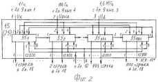
Устройство опознавания подлинника живописи на фиг.1, накопитель кодов кадра на фиг.2, блок регистров на фиг.3, 4, блок сравнения на фиг.5, общий вид одного элемента матрицы и его вид сверху на фиг.6, излучающая ячейка на фиг.7, 8, расположение элементов матрицы в экране на фиг.9, опознавание произведения живописи на фиг.10. Устройство опознавания подлинника живописи содержит /фиг.1/ устройство кодирования, блок 2 опознавания, блок 3 энергонезависимой памяти, представляемой тремя модулями флэшь-памяти, и источник света 43 с реле 44 времени /фиг.10/. Устройство 1 кодирования включает /фиг.1/ фотоэлектрический преобразователь /ФЭП/, включающий соответствующий объектив 4, матрицу 5 приборов с зарядовой инжекцией /ПЗИ/ из трехслойного КМОП-датчика [1 с.832], фоточувствительная сторона которой расположена в фокальной плоскости объектива 4, оптическое разрешение матрицы ПЗИ 1600×1000 строк /вариант/, первый-третий выходы ее подключены к входам предварительных усилителей ФЭП соответственно 6, 7, 8. Устройство 1 кодирования включает синтезатор 9 частот, первый 10 и второй 11 ключи, управляющие входы которых объединены и подключены к первому Uк выходу синтезатора 9 частот, второй выход Uс/1 кГц/ которого подключен к сигнальному входу первого ключа 10, третий выход Uд /1,6 МГц/ подключен к сигнальному входу второго ключа 11, включает три идентичных аналого-цифровых преобразователя /АЦП/ 12, 13, 14, три идентичных накопителя 15, 16, 17 кодов кадра, три идентичных блока 18, 19, 20 импульсных усилителя, каждый содержит импульсных усилителей по числу строк 1000, числу отсчетов в строке 1600 и числу разрядов в коде 8, всего 12,8×10⁶ штук, и включает плоскопанельный экран 21.The authenticating device recognition of the painting in Fig. 1, the frame code storage in Fig. 2, the register block in Figs. 3, 4, the comparison block in Fig. 5, a general view of one matrix element and its top view in Fig. 6, the emitting cell in Fig.7, 8, the location of the matrix elements in the screen of Fig.9, the recognition of the painting in Fig.10. The recognition device recognition device contains / Fig. 1/ an encoding device, anrecognition unit 2, anon-volatile memory unit 3 represented by three flash memory modules, and alight source 43 with atime relay 44/10 /. Theencoding device 1 includes / Fig. 1 / a photoelectric converter / photomultiplier / including acorresponding lens 4, a matrix 5 of devices with charge injection / FDI / from a three-layer CMOS sensor [1 p.832], the photosensitive side of which is located in the focal plane of thelens 4 , the optical resolution of the FDI matrix is 1600 × 1000 lines / option /, its first or third outputs are connected to the inputs of the pre-amplifiers of the photomultiplier tubes, respectively 6, 7, 8. Theencoding device 1 includes a synthesizer of 9 frequencies, the first 10 and second 11 keys, which control inputs x combined and connected to the first Uto the output of the synthesizer 9 frequencies, the second output Us / 1 kHz / which is connected to the signal input of the first key 10, the third output Ud / 1.6 MHz / is connected to the signal input of thesecond key 11, includes three identical analog-to-digital converters / ADCs / 12, 13, 14, threeidentical drives 15, 16, 17 frame codes, threeidentical units 18, 19, 20 of pulse amplifiers, each containing pulse amplifiers in the number of lines 1000, the number of samples in aline 1600 and the number of bits incode 8, a total of 12.8 × 10⁶ pieces, and includes a flat panel screen 21.

Блок 2 опознавания включает /фиг.1/ три идентичных блока 22, 23, 24 сравнения, каждый из которых содержит /фиг.5/ первый регистр 40, первый-восьмой входы которого подключены к первому-восьмому выходам своего АЦП, второй регистр 41, первый-восьмой входы которого подключены через разъемные соединители к первому-восьмому выходам соответствующего выхода блока 3, и с первого по восьмой логические элементы 421-8 в составе И-НЕ1-НЕ2-НЕ3, первые входы логических элементов 421-8 подключены к выходам первого-восьмого разрядов регистра 40, вторые их входы подключены к выходам первого-восьмого разрядов регистра 41 /фиг.5/, а выходы логических элементов 421-8являются первым-восьмым выходами блока 22 /23, 24/ сравнения.Therecognition unit 2 includes / Fig. 1/ three identical comparison blocks 22, 23, 24, each of which contains / Fig. 5/ thefirst register 40, the first to eighth inputs of which are connected to the first to eighth outputs of its ADC, thesecond register 41, the first to eighth inputs of which are connected through plug-in connectors to the first to eighth outputs of the corresponding output ofblock 3, and from the first to eighth logic elements 421-8 as part of I-HE1-HE2-HE3, the first inputs of logic elements 421-8 are connected to the outputs of the first to eighth digits of theregister 40, their second inputs are connected to the outputs of the first to eighth bits of theregister 41 / FIG. 5/, and the outputs of the logic elements 421-8 are the first to eighth outputs of the comparison unit 22/23, 24 /.

Блок 2 опознавания включает /фиг.1/ три накопителя 25, 26, 27 кодов кадра, идентичные блокам 15-17, три блока 28, 29, 30 импульсных усилителей, в каждом по 12,8×10⁶ импульсных усилителей /1000×1600×8/, и плоскопанельный экран 31. Состояние регистров 40, 41 в блоках 22, 23, 24 сравнения в таблице 1.Therecognition unit 2 includes / Fig. 1 / threedrives 25, 26, 27 frame codes identical to blocks 15-17, three blocks 28, 29, 30 of pulse amplifiers, each with 12.8 × 10⁶ pulse amplifiers / 1000 × 1600 × 8 /, and a flat-panel screen 31. The status of theregisters 40, 41 in the comparison blocks 22, 23, 24 in table 1.

Таблица 1Table 1Выход разряда регистра 40, опознаваемый кодRegister discharge position 40, identifiable codeВыход разряда регистра 41, код подлинникаRegister bit output 41, script codeВыход логического элемента 42Gate Output 42Результат опознания.Identification result.1one1one0 /И→НЕ1/0 / AND → HE1 /даYes00000 /НЕ2→НЕ1/0 / HE2 → HE1 /даYes1one001 /НЕ2→НЕ1/1 / HE2 → HE1 /нетno001one1 /НЕ3→HEl/1 / HE3 → HEl /нетno

Блок 3 энергонезависимой памяти включает три идентичных модуля 32, 33, 34 флэшь-памяти. Информационными входами модулей флэшь-памяти являются первый-восьмой входы 1, 2, 3 входов блока 3, подключенные через разъемные соединители к первому-восьмому выходам АЦП соответственно 12, 13, 14, управляющие входы Uд модулей флэшь-памяти подключаются через разъемные соединители и через включатель SA1 к третьему выходу синтезатора 9 частот. Выходы модулей флэшь-памяти 32, 33, 34 через разъемные соединения подключаются к 1, 2, 3 входам блоков 22, 23, 24 сравнения. При кодировании подлинника во флешь-память 32 за кадр поступают 1,6 Мбайт /1000×1600/ 8-и разрядных кодов видеосигналов R с АЦП 12 во флэшь-память 33 поступают 1,6 Мбайт кодов видеосигналов G с АЦП 13, во флэшь-память 34 поступают 1,6 Мбайт кодов, видеосигнала B с АЦП 14. При кодировании картины живописи она освечивается источником 43 света /фиг.10/. Спектр излучения источника 43 света содержит семь основных цветов, т.е. спектр близок к спектру солнечного света, лучший вариант - солнечное облучение картины. Источник 43 света запитывается через реле 44 времени, работающее в режиме "постоянно" или в режиме "один кадр" и подключено через включатель SA4 к пятому выходу синтезатора 9 частот /фиг.1/. Накопители 15 - 17 и 25 - 27 кодов кадра идентичны, каждый включает /фиг.2/ блоки 351-1000 регистров по числу строк в кадре. Информационным входом являются поразрядно объединенные первый-восьмой входы блоков 351-1000 регистров. Управляющими входами являются: первым - первый управляющий вход Uк первого блока 351 регистров, вторым - объединенные вторые управляющие входы Uвыд 100 Гц блоков 351-1000 регистров, третьим - объединенные третьи управляющие входы Uд 1,6 МГц блоков регистров 351-1000. Каждый управляющий выход предыдущего блока 35 регистров является первым управляющим входом для каждого последующего блока 35 регистров. Управляющий выход последнего блока 351000 регистров подключен параллельно к четвертым управляющим входам всех блоков 35 регистров /фиг.2/. Выходами накопителя кодов кадра 15 являются выходы всех блоков 35 регистров, всего выходов 12,8×10⁶/1600×8×1000/. Блоки 35 регистров идентичны, каждый содержит /фиг.3, 4/ первый 36, второй 37 ключи, распределитель 38 импульсов и восемь регистров 391-8, каждый из 1600 разрядов по числу отсчетов в строке. Информационными первым-восьмым входами блока 35 являются поразрядно объединенные через диоды третьи входы разрядов регистров 391-8. Выходами являются ПАРАЛЛЕЛЬНЫЕ выходы всех разрядов восьми регистров 39, которых 12800 /1600×8/, выход каждого разряда подключен и к своему третьему входу после диода. Управляющими входами блока 35 являются: первым - первый управляющий вход Uот первого ключа 36, вторым - сигнальный вход ключа 37, третьим - сигнальный вход ключа 36, четвертым - управляющий вход Uот второго ключа 37. Выход ключа 36 подключен к входу распределителя 38 импульсов, выходы которого, начиная с первого, подключены последовательно к первым /тактовым/ входам разрядов параллельно восьми регистрам 39, последний 1600 выход подключен к второму управляющему Uз входу ключа 36 и к первому управляющему входу Uот ключа 36 в следующем блоке 352 регистров. Емкость накопителя кодов 15-17 /25-27/ кадра составляет 1,6 Мбайт. Получение кода картины выполняется за один кадр /1 сек./. Для воспроизведения изображения на экране 21 длительное время сигналы кодов кадра в блоках 351-1000 регистров /фиг.3, 4/ сохраняются до выключения питания в устройстве 1 кодирования.Block 3 non-volatile memory includes threeidentical modules 32, 33, 34 flash memory. The information inputs of flash memory modules are the first toeighth inputs 1, 2, 3 ofblock 3 inputs connected via plug-in connectors to the first to eighth ADC outputs, respectively 12, 13, 14, the control inputs Ud of flash memory modules are connected via plug-in connectors and through the switch SA1 to the third output of the synthesizer 9 frequencies. The outputs of theflash memory modules 32, 33, 34 through plug-in connections are connected to 1, 2, 3 inputs of comparison blocks 22, 23, 24. When encoding the original, in the flash memory 32, 1.6 MB / 1000 × 1600/8-bit video codes of the R signals from the ADC are received per frame 12; 1.6 MB of the G signals from the ADC 13 enter the flash memory 33, the flash-memory 34 receives 1.6 MB of codes, video signal B from the ADC 14. When encoding a painting, it is illuminated by a source oflight 43 / 10/10. The emission spectrum of thelight source 43 contains seven primary colors, i.e. the spectrum is close to the spectrum of sunlight, the best option is the solar radiation of the picture. Thelight source 43 is energized via atime relay 44, operating in the "continuous" mode or in the "single frame" mode and connected through the switch SA4 to the fifth output of the frequency synthesizer 9/1 /. Drives 15 - 17 and 25 - 27 frame codes are identical, each includes / Fig. 2/ blocks 351-1000 registers according to the number of lines in the frame. The information input is the bitwise integrated first-eighth inputs of the blocks 351-1000 registers. The control inputs are: the first is the first control input Uto the first block of 351 registers, the second is the combined second control inputs Uoutput 100 Hz of the blocks 351-1000 registers, the third is the combined third control inputs Ud 1.6 MHz of the blocks of registers 351 -1000 . Each control output of the previous block of registers 35 is the first control input for each subsequent block of 35 registers. The control output of the last block of 351000 registers is connected in parallel to the fourth control inputs of all blocks of 35 registers / Fig.2/. Outputs of thedrive frame 15 codes are outputs of all the blocks of registers 35, only outputs 12.8 × 10⁶/1600 × 8 × 1000 /. Blocks 35 registers are identical, each contains / Fig. 3, 4 / first 36, second 37 keys, a distributor of 38 pulses and eight registers 391-8 , each of 1600 digits according to the number of samples in a row. Information first-eighth inputs of block 35 are bitwise combined through diodes the third inputs of the bits of the registers 391-8 . The outputs are the PARALLEL outputs of all bits of eight registers 39, of which 12800/1600 × 8 /, the output of each bit is connected to its third input after the diode. The control inputs of block 35 are: the first is the first control input Ufrom the first key 36, the second is the signal input of the key 37, the third is the signal input of the key 36, the fourth is the control input Ufrom the second key 37. The output of the key 36 is connected to the input of thepulse distributor 38 which outputs from the first, connected in series to the first / clock / input bits in parallel eight registers 39, the last 1600 output is connected to the second control Uof input key 36 and to the first control U entryfrom the key 36, a next block 352 registers. The capacity of the drive codes 15-17 / 25-27 / frame is 1.6 MB. Obtaining the picture code is performed in one frame / 1 sec. /. To reproduce the image on the screen 21 for a long time, the signals of the frame codes in blocks 351-1000 registers / 3, 4 / are stored until the power is turned off in theencoding device 1.

Сохранение кодов в регистрах 391-8 выполняется возвращением сигналов при выдаче из регистров 39 вновь в свой разряд, для этого выхода разрядов подключены к третьим входам их после диодов, которые предохраняют от смешивания сигналов. Плоскопанельные экраны 21 и 31 выполнены идентично, каждый содержит элементы матрицы 1,6×10⁶пикселов /1600×1000/. Каждый элемент матрицы формирует пиксел тремя излучающими ячейками, излучающие базовые цвета R, G, B. Общий вид элемента матрицы и его вид сверху на фиг.6 и включает непрозрачный корпус 45 соответствующей формы, объединяющий три излучающие ячейки 46, 47, 48. Левая ячейка 46 излучает красный R цвет, верхняя 47 излучает зеленый G цвет, нижняя правая 48 излучает синий B цвет. Каждая излучающая ячейка содержит /фиг.7, 8/ в переднем торце корпуса 45 микролинзу 49, выполняющую роль микрообъектива, в выходном торце корпуса закреплен цветной светофильтр 50 одного из базовых цветов, между микролинзой 49 и цветным светофильтром 50 расположена диафрагма 51, имеющая цилиндрический корпус 52 с восемью прорезями, в которых расположены восемь нейтральных микросветофильтров 531-8, прикрепленные к своим микропьезоэлементам 541-8 с двумя управляющими входами. Первые торцы микропьезоэлементов 54 с двумя управляющими входами жестко закреплены в корпусе элемента матрицы 45, к вторым свободным концам микропьезоэлементов 54 прикреплены нейтральные микросветофильтры 53, которые в отсутствие управляющих импульсов с блоков 18-20 /20-30/ полностью перекрывают поток излучения от микролинзы 49. Излучающие ячейки работают идентично. Принцип их действия основан на том, что каждый нейтральный микросветофильтр 53 ослабляет поток излучения соответственно весу своего разряда в коде, коэффициенты ослабления приведены в таблице 2. Значения коэффициентов ослабления соответствуют принципу двоичного кода. Микросветофильтры 53 расположены друг за другом по оптической оси микролинзы 49 в порядке уменьшения значений коэффициентов ослабления, нейтральный микросветофильтр 531 с наибольшим коэффициентом расположен первым от микролинзы 49 /фиг.7/. Излучение от источников облучения /подсветки/ сверхяркими светодиодами белого свечения микролинзой 49 направляется сквозь нейтральные микросветофильтры на цветной светофильтр 50 /фиг.7/, придающий излучению соответствующий цвет.Saving codes in registers 391-8 is performed by returning the signals when issuing from registers 39 again to their category, for this output the bits are connected to their third inputs after the diodes, which protect against signal mixing. Flat panel screens 21 and 31 are identical, each containing matrix elements of 1.6 × 106 pixels / 1600 × 1000 /. Each matrix element forms a pixel with three radiating cells emitting the basic colors R, G, B. The general view of the matrix element and its top view in Fig. 6 includes anopaque housing 45 of the corresponding shape, combining three radiatingcells 46, 47, 48. Theleft cell 46 emits red R color, upper 47 emits green G color, lower right 48 emits blue B color. Each emitting cell contains / Fig. 7, 8 / in the front end of the housing 45 amicrolens 49, which acts as a micro lens, in the output end of the body is fixed acolor filter 50 of one of the basic colors, between themicrolens 49 and thecolor filter 50 there is adiaphragm 51 having acylindrical body 52 with eight slots, in which eightneutral microfilter 531-8 are located , attached to their micropiezoelectric elements 541-8 with two control inputs. The first ends of the micropiezoelectric elements 54 with two control inputs are rigidly fixed in the housing of thematrix element 45, neutral microfilter filters 53 are attached to the second free ends of the micropiezoelectric elements 54, which, in the absence of control pulses from blocks 18-20 / 20-30 / completely block the radiation flux from themicrolens 49. Emitting cells work identically. The principle of their operation is based on the fact that eachneutral microfilter 53 attenuates the radiation flux according to the weight of its discharge in the code, the attenuation coefficients are shown in table 2. The attenuation coefficients correspond to the principle of a binary code. Themicrofilter 53 is located one after another along the optical axis of themicrolens 49 in order of decreasing attenuation coefficients, theneutral microfilter 531 with the largest coefficient is located first from themicrolens 49/7 /. The radiation from the sources of irradiation / backlight / super-bright white LEDs with themicrolens 49 is directed through the neutral micro-filters to the color filter 50 (Fig. 7/), which gives the radiation the corresponding color.

Таблица 2table 2Номер разрядаDischarge numberВес разряда в кодеCodeWeightКоэффициент ослабленияAttenuation coefficient1 старший1 senior27/128/July2/128 /0.50.550%fifty%2226/64/February6/64 /0,250.2525%25%3325/32/2 May / 32 /0,1250.125--4four24/16/April2/16 /0,06250.0625--5523/8/2 March / 8 /0,031250,03125--6622/4/February2/4 /0,0156250.015625--7721/2/21/2 /0,00780.00780,78%0.78%8820/1/20/1 /0,00390.00390.39%0.39%

Входы микропьезоэлементов 54 являются управляющими входами элемента матрицы и подключены к выходам соответствующих импульсных усилителей 18-20 /28-30/. В отсутствие управляющих импульсов /сигналов единиц кода/ микропьезоэлементы 54 находятся в ненапряженном состоянии, все микросветофильтры 531-8 расположены по оси микролинзы и полностью перекрывают поток излучения. При поступлении управляющего сигнала на микропьезоэлемент 54 его свободный конец изгибается и выводит свой нейтральный микросветофильтр 53 из потока излучения на длительность управляющего импульса 10 мс, чтобы он не перекрывал поток, что соответствует единице в разряде кода, не выведенный из потока микросветофильтр 53 соответствует нулю в разряде кода. При поступлении кода из одних единиц 11111111 из потока выводятся все микросветофильтры 531-8: из ячейки идет максимальное излучение. При поступлении разных кодов из потока излучения выводятся нейтральные микросветофильтры 53, соответствующие единицам в разрядах кода.The inputs of the micropiezoelectric elements 54 are the control inputs of the matrix element and are connected to the outputs of the respective pulse amplifiers 18-20 / 28-30 /. In the absence of control pulses / signals of code units / micro-piezoelectric elements 54 are in an unstressed state, all micro-filters 531-8 are located along the axis of the microlens and completely block the radiation flux. When the control signal arrives at the micropiezoelectric element 54, its free end bends and removes itsneutral microfilter 53 from the radiation flux for a duration of the control pulse of 10 ms, so that it does not block the flux, which corresponds to a unit in the code discharge, themicrofilter 53 not removed from the flux corresponds to zero in the discharge code. Upon receipt of the code from one unit 11111111, all micro-filters 531-8 are removed from the stream: the maximum radiation comes from the cell. Upon receipt of different codes from the radiation flux, neutral microfilter filters 53 corresponding to units in the bits of the code are output.

В качестве микропьезоэлементов 54 применяются трубчатые пьезоэлементы, работающие на изгиб, прочные и надежные для длительной работы [2 с.27]. Элементы излучающих ячеек выполняются максимально миниатюрными для получения элементов матриц размером 2×2 мм. Излучающие ячейки изготавливаются отдельно и объединяются в корпусе 45 /фиг.6/, а из элементов матрицы набирается экран /фиг.9/. Излучающие ячейки выполняют преобразование "код-яркость излучения". Излучение трех ячеек формирует пиксел яркостью и цветовым тоном соответственно трем кодам R, G, B. Облучение /подсветка/ микролинз 49 элементов матрицы выполняется светодиодами белого свечения, расположенными в соответствующем количестве и в соответствующем порядке на тыльной стороне внутри корпусов экранов 21, 31 таким образом, что каждый светодиод облучает несколько элементов матрицы. Синтезатор 9 частот выдает /фиг.1/ с первого выхода импульсы 1 Гц на открытие ключей 10, 11 на длительность 1 секунды, со второго выхода выдает импульсы 1 кГц частоты строк для считывания сигналов пикселов по строкам, с третьего выхода импульсы 1,6 МГц для считывания сигналов пикселов в строке, с четвертого выхода выдает сигналы Uвыд 100 Гц для выдачи кодов из накопителей 15-17 и 25-27 кодов и с пятого выхода импульс длительностью 1 секунда через включатель SA4 в реле 44 времени.As the micro-piezoelectric elements 54, tubular piezoelectric elements are used, which work on bending, are strong and reliable for long-term operation [2 p. 27]. Elements of radiating cells are made as miniature as possible to obtainmatrix elements 2 × 2 mm in size. The emitting cells are manufactured separately and combined in thehousing 45 / Fig.6/, and from the elements of the matrix the screen / Fig.9/ is typed. Emitting cells perform a code-to-luminance conversion. The radiation of three cells forms a pixel with brightness and color tone, respectively, of the three codes R, G, B. Irradiation / illumination / microlens of 49 matrix elements is performed by white LEDs located in the corresponding quantity and in the corresponding order on the back side inside the screen cases 21, 31 in this way that each LED irradiates several elements of the matrix. A frequency synthesizer 9 generates / Fig. 1/ from the first output pulses of 1 Hz for openingkeys 10, 11 for a duration of 1 second, from the second output generates pulses of 1 kHz line frequency for reading pixel signals in lines, from the third output pulses of 1.6 MHz for reading pixel signals in a row, from the fourth output it gives signals Uvy 100 Hz for issuing codes from the 15-17 and 25-27 code drives and from the fifth output a pulse of 1 second duration through the switch SA4 in the 44 time relay.

Формирование кода подлинника произведения живописи.Formation of the original code of the painting.

Оригинал картины устанавливается в подготовленное место /фиг.10/ в поле зрения объектива 4. Включается питание устройства 1 кодирования, включается включатель SA2 /фиг.1/, включателем SA5 включается источник 43 света в режим "постоянно" /фиг.10/. Сигнал Uк открывает ключи 10, 11, импульсы дискретизации 1,6 МГц считывают видеосигналы R, G, B пикселов, которые поступают в предварительные усилители 6, 7, 8. АЦП 12, 13, 14 преобразуют видеосигналы в 8-и разрядные коды, поступающие в накопители кодов 15-17, в которых за первый период кадра сосредотачиваются коды кадра. По окончании кадра коды с частотой 100 Гц выдаются в импульсные усилители блоков 18, 19, 20, где сигналы формируются по амплитуде и длительностью 10 мс и поступают в излучающие ячейки экрана 21, на экране 21 появляется изображение картины, которое объективом 4 выводится на максимальную резкость. Включатель SA5 выключается, источник 43 света обесточивается /фиг.10/, выключается питание устройства 1 кодирования. Первый-третий входы блока 3 /фиг.1/ через гнезда разъмных соединений подключаются к первому-третьему выходам устройства 1 кодирования, включается SA1. Реле времени 44 /фиг.10/ имеет два режима работы: первый режим "постоянно" включает источник 43 света на длительное освечивание картины, второй режим "один кадр" включает источник 43 на одну секунду, т.е. на один кадр. Включается питание устройства 1 кодирования, оператор включает SA4, в реле 44 поступает сигнал 1 Гц, источник 43 света облучает картину одну секунду, в ПЗИ 5 считываются видеосигналы кадра, коды с АЦП 12, 13, 14 поступают во флэшь-памяти 32, 33,34. На экране 21 появляется изображение картины, по которому оператор заключает, что в блоке 3 зарегистрированы коды картины подлинника.The original picture is set in the prepared place / Fig. 10/ in the field of view of thelens 4. The power of theencoding device 1 is turned on, the switch SA2 / Fig. 1/ is turned on, and thelight source 43 is turned on by the switch SA5 in the "continuous" / Fig. 10/ mode. The signal Uk opens thekeys 10, 11, the sampling pulses of 1.6 MHz read the video signals R, G, B pixels, which are fed to the pre-amplifiers 6, 7, 8. The ADCs 12, 13, 14 convert the video signals into 8-bit codes, arriving in the drive codes 15-17, in which the frame codes are concentrated for the first period of the frame. At the end of the frame, codes with a frequency of 100 Hz are issued to the pulse amplifiers ofblocks 18, 19, 20, where the signals are generated by the amplitude and duration of 10 ms and fed into the emitting cells of the screen 21, a picture of the picture appears on the screen 21, which is displayed by thelens 4 for maximum sharpness . The switch SA5 is turned off, thelight source 43 is de-energized / 10 /, the power of theencoding device 1 is turned off. The first or third inputs ofblock 3 / Fig. 1/ are connected to the first and third outputs of theencoding device 1 through the connectors of detachable connections, SA1 is turned on. Thetime relay 44 / Fig. 10/ has two operating modes: the first mode "constantly" turns on thelight source 43 for long-term coverage of the picture, the second mode "one frame" turns on thesource 43 for one second, i.e. on one frame. The power of theencoding device 1 is turned on, the operator turns on SA4, the 1 Hz signal is supplied to relay 44, thelight source 43 irradiates the picture for one second, the frame video signals are read in FDI 5, the codes from the ADC 12, 13, 14 enter theflash memory 32, 33, 34. On the screen 21, an image of the picture appears, according to which the operator concludes that the original picture codes are registered inblock 3.

Опознавание картины, претендующей на подлинник.Identification of a picture claiming to be original.

Проверяемая картина устанавливается на место подлинника /фиг.10/. Включаются SA2, питание устройства 1 кодирования, источник 43 света включается в режим "постоянно". На экране 21 появляется изображение картины, которое объективом 4 выводится на максимальную резкость. Затем выключается источник 43 света, выключается питание устройства 1 кодирования, первый-третий выходы блока 3 через гнезда разъемных соединений подключаются к первому-третьему входам блока 2 опознания. Управляющие Uд входы блоков 32, 33, 34 включателем SA1 подключаются к соответствующим выходам разъемных соединений Uд, управляющие входы блоков 22, 23, 24 подключаются включателем SA3 к третьему выходу синтезатора 9 частот, включается включатель SA2. Реле 44 времени ставится в режим "один кадр". Включается питание устройства 1 кодирования, оператор включает SA4: реле 44 включает источник 43 света на один кадр. АЦП 12, 13, 14 выдают коды, которые поступают в накопители 15-17 кодов кадра и в блоки 22, 23, 24 сравнения в регистры 40 /фиг.5/. Сигналы Uд поступают на соответствующие входы флэшь-памяти 32, 33, 34 и выдают коды подлинника на входы через разъемные соединения 1-3 блоков 22, 23, 24 сравнения, которые выполняют сравнение кодов R, G, B проверяемой картины с АЦП 12-14 с кодами подлинника с блока 3. Результаты разницы кодов поступают в накопители 25-27 кодов кадра и отображаются на экране 31. При полном совпадении кодов на экране 31 изображение отсутствует, при частичном несовпадении кодов на экране 31 будет искаженное изображение, либо его отрывки, что и будет наблюдаться присутствующими. Заявляемое устройство может быть использовано для проведения цифровой паспортизации подлинников картин в музеях и в частных коллекциях, а поступающие картины проверять на подлинность.Checked picture is installed in place of the original / Fig.10/. Turns on SA2, the power of theencoding device 1, thelight source 43 is turned on in the "constant" mode. An image of the picture appears on the screen 21, which is displayed by thelens 4 at maximum sharpness. Then thelight source 43 is turned off, the power of theencoding device 1 is turned off, the first or third outputs ofblock 3 are connected to the first or third inputs of therecognition block 2 via plug-in connectors. The control Ud inputs of theblocks 32, 33, 34 by the switch SA1 are connected to the corresponding outputs of the plug-in connections Ud , the control inputs of the blocks 22, 23, 24 are connected by the switch SA3 to the third output of the frequency synthesizer 9, the switch SA2 is turned on. Thetime relay 44 is set to "single frame" mode. The power of theencoding device 1 is turned on, the operator turns on SA4: therelay 44 turns on thelight source 43 for one frame. The ADCs 12, 13, 14 issue codes that enter the drives 15-17 frame codes and into blocks 22, 23, 24 of the comparison in theregisters 40/5 /. The signals Ud are fed to the corresponding inputs of theflash memory 32, 33, 34 and give the original codes to the inputs via detachable connections 1-3 comparison blocks 22, 23, 24, which compare the codes R, G, B of the checked picture with the ADC 12- 14 with the original codes fromblock 3. The results of the difference between the codes are transmitted to the drives 25-27 frame codes and displayed on screen 31. If the codes match on screen 31 completely, there is no image, with partial mismatch of codes on screen 31 there will be a distorted image, or fragments of it, which will be observed by those present. The inventive device can be used for digital certification of original paintings in museums and in private collections, and incoming paintings to check for authenticity.

Использованные источникиUsed sources

1. Колесниченко О.В, Шишигин И.В. Аппаратные средства PC. 5-е изд-е, СПб, 2004, с.832-833.1. Kolesnichenko O.V., Shishigin I.V. PC hardware. 5th ed., St. Petersburg, 2004, p. 832-833.

2. А.Ф.Плонский, В.И.Теаро. Пьезоэлектроника. М., 1979, с.27.2. A.F. Plonsky, V.I. Thearo. Piezoelectronics. M., 1979, p. 27.

3. Гук М.Ю. Аппаратные средства IBM PC. Энциклопедия, 3-е. изд., СПб., 2006, с.415.3. Guk M.Yu. Hardware IBM PC. Encyclopedia, 3rd. ed., St. Petersburg., 2006, p. 415.

4. В.В.Фролов. Язык радиосхем. Изд-е 2-е. М., 1989, с.56 фиг.99 а.4. V.V. Frolov. The language of the radio circuits. 2nd ed. M., 1989, p. 56 Fig. 99 a.

Claims (1)

Translated fromRussian
Устройство опознавания подлинника живописи, отличающееся тем, что выполняется в составе устройства кодирования, блока опознавания, блока энергонезависимой памяти и источника света с реле времени, устройство кодирования содержит фотоэлектрический преобразователь /ФЭП/, включающий объектив, матрицу приборов с зарядовой инжекцией /ПЗИ/, фоточувствительная сторона которой расположена в фокальной плоскости объектива, первый-третий выходы матрицы ПЗИ подключены к входам соответственно первого, второго и третьего предварительных усилителей ФЭП, устройство кодирования включает синтезатор частот, первый и второй ключи, выходы которых подключены к первому и второму входам матрицы ПЗИ, управляющие входы ключей объединены и подключены к первому выходу Uк синтезатора частот, второй выход Uскоторого подключен к сигнальному входу первого ключа, третий выход Uдподключен к сигнальному входу второго ключа, включает три идентичных аналого-цифровых преобразователя /АЦП/, три идентичных накопителя кодов кадра, три идентичных блока импульсных усилителей, каждый из которых содержит импульсных усилителей по числу строк, отсчетов в строке и числу разрядов в коде /1000·1600·8/, и включает плоскопанельный экран, информационные входы первого, второго, третьего АЦП подключены к выходам соответственно первого, второго и третьего предварительных усилителей, управляющие Uд входы трех АЦП объединены и подключены к третьему выходу Uд синтезатора частот, первый-восьмой выходы первого-третьего АЦП подключены к первому-восьмому входам соответственно первого, второго, третьего накопителей кодов кадра, выходы каждого из которых подключены к стольким же входам своего блока импульсных усилителей, а выходы блоков импульсных усилителей подключены к соответствующим входам плоскопанельного экрана, одноименные первый, второй и третий управляющие входы первого-третьего накопителей кодов кадра объединены и подключены: первые - к первому выходу Uк синтезатора частот, вторые - к четвертому выходу Uвыд /100 Гц/ синтезатора частот, третьи - к третьему выходу Uд синтезатора частот через включатель SA2, устройство кодирования содержит включатели SA1, SA2, SA3, входы которых объединены и подключены к третьему выходу синтезатора частот, и содержит включатель SA4, вход которого подключен к пятому выходу синтезатора частот, блок опознания включает три идентичных блока сравнения, три накопителя кодов кадра, идентичные накопителям кодов кадра устройства кодирования, три идентичных блока импульсных усилителей, каждый из которых содержит импульсных усилителей по числу строк, отсчетов в строке и числу разрядов в коде, и включает плоскопанельный экран, первые информационные первый-восьмой входы первого, второго и третьего блоков сравнения подключены к первому-восьмому выходам соответственно первого, второго и третьего АЦП, управляющие входы Uд первого-третьего блоков сравнения объединены и через включатель SA3 подключены к третьему выходу Uд синтезатора частот, вторые информационные первый-восьмой входы блоков сравнения подключены через разъемные соединители к выходам соответствующих первого, второго, третьего выходов блока энергонезависимой памяти, первый-восьмой выходы первого, второго, третьего блоков сравнения подключены к первому-восьмому входам соответственно первого, второго и третьего накопителей кодов кадра и параллельно являются выходами кодов R, G, B во внешнее устройство регистрации, одноименные первый, второй, третий управляющие входы первого-третьего накопителей кодов кадра объединены и подключены: первые - к первому выходу Uксинтезатора частот, вторые - к четвертому Uвыд выходу синтезатора частот, третьи - к третьему выходу синтезатора частот через включатель SA2, выходы каждого накопителя кодов кадра подключены к входам своего блока импульсных усилителей, выходы блоков импульсных усилителей подключены к соответствующим входам плоскопанельного экрана, блоки сравнения идентичны, каждый содержит первый и второй, восьмиразрядные регистры и по числу разрядов в них содержит восемь логических элементов, входы первого-восьмого разрядов первого регистра являются первыми информационными входами блока сравнения и подключены к первому-восьмому выходам своего АЦП, первый-восьмой входы разрядов второго регистра являются вторыми информационными входами блока сравнения и подключены через разъемные соединители к первому-восьмому выходам соответствующего выхода блока энергонезависимой памяти, управляющие входы Uд обоих регистров объединены и подключены через включатель SA3 к третьему выходу синтезатора частот, логические элементы выполнены идентично, каждый включает элемент И, первый и второй входы которого подключены к выходам одноименных разрядов первого и второго регистров, первый элемент НЕ1, вход которого подключен к выходу элемента И, а выход элемента НЕ1 является выходом логического элемента, включает второй элемент НЕ2 и третий элемент НЕ3, выходы которых подключены к входу элемента НЕ1, вход второго элемента НЕ2 подключен к первому входу логического элемента, вход третьего элемента НЕ3 подключен к второму входу логического элемента, выходы первого-восьмого логических элементов являются первым-восьмым выходами блока сравнения, накопители кодов кадра устройства кодирования и блока опознавания выполнены идентично, каждый включает блоки регистров по числу строк /1000/ в кадре, информационным входом накопителя кодов кадра являются поразрядно объединенные первый-восьмой информационные входы блоков регистров, управляющими входами являются: первым - первый управляющий вход Uк первого блока регистров, вторым - объединенные вторые управляющие Uвыд входы блоков регистров, третьим - объединенные третьи управляющие входы Uд блоков регистров, каждый управляющий выход предыдущего блока регистров является первым управляющим входом для каждого последующего блока регистров, управляющий выход последнего блока регистров подключен параллельно к четвертым управляющим входам всех блоков регистров, выходами накопителя кодов кадра являются параллельные выходы всех блоков регистров, блоки регистров идентичны, каждый содержит первый и второй ключи, распределитель импульсов и восемь регистров, каждый по числу отсчетов в строке из 1600 разрядов, первыми-восьмыми информационными входами блока регистров являются поразрядно объединенные через диоды третьи входы разрядов восьми регистров, выходами являются параллельные выходы всех разрядов восьми регистров /1600·8/, выход каждого разряда подключен к третьему входу своего разряда после диода, управляющими входами являются: первым - первый управляющий вход Uот первого ключа, вторым - сигнальный вход второго ключа, третьим - сигнальный вход первого ключа, четвертым - управляющий вход Uот второго ключа, выход первого ключа подключен к входу распределителя импульсов, выходы которого, начиная с первого, последовательно подключены к первым /тактовым/ входам разрядов параллельно восьми регистрам, последний выход /1600/ подключен к второму управляющему U3 входу первого ключа и является управляющим выходом блока регистров в следующий блок регистров, плоскопанельные экраны идентичны, каждый содержит элементы матрицы соответственно разрешения экрана 1,6·106/1600·1000/ пикселов, каждый элемент матрицы из трех излучающих ячеек, объединенных в непрозрачном корпусе элемента матрицы, левая нижняя излучающая ячейка излучает красный R цвет, верхняя излучает зеленый G цвет, правая нижняя излучает синий B цвет, каждая излучающая ячейка содержит в переднем торце корпуса элемента микролинзу, в выходном торце корпуса закреплен цветной светофильтр одного из базовых цветов R, G, B, между микролинзой и цветным светофильтром размещается диафрагма, имеющая цилиндрический корпус с восемью прорезями, в которых по оси микролинзы расположены восемь нейтральных микросветофильтров с соответствующими коэффициентами ослабления потока излучения, нейтральные микросветофильтры прикреплены к своим микропьезоэлементам, первые концы микропьезоэлементов с двумя управляющими входами жестко закреплены в корпусе элемента матрицы, к вторым свободным концам их прикреплены нейтральные микросветофильтры, каждый из которых ослабляет поток излучения соответственно весу своего разряда в коде, значения коэффициентов ослабления соответствуют принципу двоичного кода, нейтральные микросветофильтры расположены друг за другом в порядке уменьшения коэффициентов ослабления, нейтральный микросветофильтр с наибольшим коэффициентом ослабления расположен первым от микролинзы, управляющими входами излучающих ячеек являются управляющие входы микропьезоэлементов, подключенные к соответствующим выходам блока импульсных усилителей, облучение /подсветка/ микролинз элементов матрицы выполняется светодиодами белого свечения, расположенными в соответствующем количестве и в соответствующем порядке в тыльной части корпусов экранов, блок энергонезависимой памяти включает три идентичных модуля флэш-памяти, информационными входами которых являются первый-восьмой входы модулей флэш-памяти, подключенные через гнезда разъемных соединителей к первому-восьмому выходам соответственно первого, второго и третьего АЦП устройства кодирования, управляющие входы модулей флэш-памяти подключены через гнезда разъемных соединителей и через включатель SA1 к третьему выходу Uд синтезатора частот, а первый-восьмой выходы модулей флэш-памяти через гнезда разъемных соединителей подключены к входам соответственно первого, второго и третьего блоков сравнений в блоке опознания, источник света с соответствующим спектром излучения запитывается через реле времени, работающим в режиме "постоянно" или "один кадр", подключенное через включатель SA4 к пятому выходу синтезатора частот в устройстве кодирования.A painting original identification device, characterized in that it is a part of an encoding device, an recognition unit, a non-volatile memory unit and a light source with a time relay, the encoding device contains a photoelectric converter / photomultiplier / including a lens, a matrix of charge-injected devices / PZI /, photosensitive the side of which is located in the focal plane of the lens, the first or third outputs of the FDI matrix are connected to the inputs of the first, second, and third preamplifiers, respectively minutes FEP, the encoder includes a frequency synthesizer, the first and second switches, the outputs of which are connected to first and second inputs of the matrix FDI, control inputs of the keys are coupled and connected to the first output Uto the frequency synthesizer, the second output Ufrom which is connected to the signal input of the first switch , the third output Ud is connected to the signal input of the second key, includes three identical analog-to-digital converters / ADC /, three identical drive codes for the frame, three identical blocks of pulse amplifiers, each of which contains and pulse amplifiers according to the number of lines, samples per line and the number of bits in the code / 1000 · 1600 · 8 /, and includes a flat panel screen, the information inputs of the first, second, third ADCs are connected to the outputs of the first, second and third pre-amplifiers, controlling Ud the inputs of the three ADCs are combined and connected to the third output Ud of the frequency synthesizer, the first to eighth outputs of the first to third ADCs are connected to the first to eighth inputs of the first, second, third drives of the frame codes, the outputs of each of which are connected the same inputs of its block of pulse amplifiers, and the outputs of the blocks of pulse amplifiers are connected to the corresponding inputs of the flat panel screen, the first, second, and third control inputs of the first and third drive codes of the frame are combined and connected: the first to the first output Uto the frequency synthesizer, second - the fourth outputvyd U / 100 Hz / frequency synthesizer, the third - the third output of the frequency synthesizer Ud through switch SA2, the encoding apparatus comprises switches SA1, SA2, SA3, and the inputs of which are combined under are connected to the third output of the frequency synthesizer, and contains an SA4 switch, the input of which is connected to the fifth output of the frequency synthesizer, the recognition unit includes three identical comparison units, three frame code drives, identical to the drive codes of the encoding device frame, three identical pulse amplifier units, each of which contains pulse amplifiers in terms of the number of lines, samples in a line and the number of bits in the code, and includes a flat panel screen, the first informational first-eighth inputs of the first, second and third blocks inputs are connected to the first to eighth outputs of the first, second and third ADCs, the control inputs Ud of the first to third comparison units are combined and through the SA3 switch are connected to the third output Ud of the frequency synthesizer, the second information first to eighth inputs of the comparison units are connected via detachable connectors to the outputs of the corresponding first, second, third outputs of the non-volatile memory block, the first to eighth outputs of the first, second, third comparison blocks are connected to the first to eighth inputs of respectively Similarly, the first, second and third drives of frame codes and in parallel are the outputs of codes R, G, B to an external recording device, the first, second, third names of the same control inputs of the first and third drives of frame codes are combined and connected: the first to the first output Uto the synthesizer frequency, the second - the fourth Uvyd synthesizer output frequencies, others - to the third output of the frequency synthesizer through a switch SA2, the outputs of each of the frame codes accumulator connected to inputs of its block pulse amplifier block outputs pulse amplifiers are connected to the corresponding inputs of the flat panel screen, the comparison blocks are identical, each contains the first and second, eight-bit registers and contains eight logic elements by the number of bits in them, the inputs of the first to eighth bits of the first register are the first information inputs of the comparison block and are connected to the first-eighth the outputs of its ADC, the first to eighth inputs of the bits of the second register are the second information inputs of the comparison unit and are connected through plug-in connectors to the first the eighth outputs of the corresponding output of the non-volatile memory block, the control inputs Ud of both registers are combined and connected via the SA3 switch to the third output of the frequency synthesizer, the logic elements are identical, each includes an And element, the first and second inputs of which are connected to the outputs of the same bits of the first and second registers , the first element HE1, the input of which is connected to the output of the AND element, and the output of the element HE1 is the output of the logic element, includes the second element HE2 and the third element HE3, outputs which are connected to the input of the element HE1, the input of the second element HE2 is connected to the first input of the logic element, the input of the third element HE3 is connected to the second input of the logic element, the outputs of the first to eighth logical elements are the first to eighth outputs of the comparison unit, the code codes of the frame of the encoding device and block the identifications are performed identically, each of them includes blocks of registers by the number of lines / 1000 / in the frame, the information input of the frame code storage device is the bitwise integrated first-eighth information e inputs of the register blocks, the control inputs are: the first is the first control input Uto the first block of registers, the second is the combined second control Uoutput of the inputs of the register blocks, the third is the combined third control inputs Ud of the register blocks, each control output of the previous register block is the first the control input for each subsequent block of registers, the control output of the last block of registers is connected in parallel to the fourth control inputs of all blocks of registers, the outputs of the code storage frame and are the parallel outputs of all register blocks, the register blocks are identical, each contains the first and second keys, a pulse distributor and eight registers, each according to the number of samples in a row of 1600 bits, the first or eighth information inputs of the register block are the third bit inputs that are bit-wise connected through diodes eight registers, the outputs are the parallel outputs of all the bits of the eight registers / 1600 · 8 /, the output of each bit is connected to the third input of its category after the diode, the control inputs are : First - the first control U inputfrom a first key, the second - the signal input of the second switch, the third - the signal input of the first switch, the fourth - the control input Ufrom the second switch, the first switch output is connected to the input of the pulse distributor which outputs from the first, connected in series to the first / clock / input bits in parallel eight registers, the last output / 1600 / is connected to the second control input U3 is a first key and a control output register block to the next block of registers, Flat Panel e wounds are identical, each comprising respectively elements of a matrix display resolution of 1.6 × 10⁶/1600 · 1000 / pixel, each element of the matrix of cells emitting three united in an opaque matrix body member bottom left-emitting cell emits red color R, the upper emits green G color, the lower right one emits blue B color, each emitting cell contains a microlens in the front end of the element body, a color filter of one of the basic colors R, G, B is fixed in the output end of the case, between the micro lens and the color filter a diaphragm is placed having a cylindrical body with eight slots, in which eight neutral microfilter filters with corresponding attenuation coefficients of radiation are located along the microlens axis, neutral microfilter filters are attached to their micropiezoelectric elements, the first ends of micropiezoelectric elements with two control inputs are rigidly fixed in the matrix element housing, to the second free neutral microfilter filters are attached to their ends, each of which attenuates the radiation flux according to the weight of discharge in the code, attenuation coefficients correspond to the binary code principle, neutral microfilter filters are arranged one after another in decreasing attenuation coefficient, the neutral microfilter with the largest attenuation coefficient is located first from the microlens, the control inputs of the emitting cells are the control inputs of the micropiezoelectric elements connected to the corresponding outputs of the block pulse amplifiers, irradiation / backlight / microlens of matrix elements is performed by white LEDs of luminescence, located in the corresponding number and in the corresponding order in the back of the screen cases, the non-volatile memory unit includes three identical flash memory modules, the information inputs of which are the first to eighth inputs of the flash memory modules connected through the socket connectors to the first to eighth the outputs of the first, second and third ADCs of the encoding device, the control inputs of the flash memory modules are connected via plug-in connectors and through the switch SA1 to third he output Ud a frequency synthesizer, and the first to eighth outputs flash memory modules via socket separable connectors are connected to the inputs of respective first, second and third blocks comparisons in the identification block, a light source with an appropriate radiation spectrum supplied via time switch operating mode " permanently "or" one frame "connected through switch SA4 to the fifth output of the frequency synthesizer in the encoding device.
RU2011112524/08A2011-04-012011-04-01Device for identification of painting originalRU2447500C1 (en)

Priority Applications (1)

Application NumberPriority DateFiling DateTitle
RU2011112524/08ARU2447500C1 (en)2011-04-012011-04-01Device for identification of painting original

Applications Claiming Priority (1)

Application NumberPriority DateFiling DateTitle
RU2011112524/08ARU2447500C1 (en)2011-04-012011-04-01Device for identification of painting original

Publications (1)

Publication NumberPublication Date
RU2447500C1true RU2447500C1 (en)2012-04-10

Family

ID=46031810

Family Applications (1)

Application NumberTitlePriority DateFiling Date
RU2011112524/08ARU2447500C1 (en)2011-04-012011-04-01Device for identification of painting original

Country Status (1)

CountryLink
RU (1)RU2447500C1 (en)

Cited By (1)

* Cited by examiner, † Cited by third party
Publication numberPriority datePublication dateAssigneeTitle
CN112834507A (en)*2020-12-312021-05-25易旻Uniqueness identification system and method based on image registration and spectrum identification

Citations (4)

* Cited by examiner, † Cited by third party
Publication numberPriority datePublication dateAssigneeTitle
RU2205450C1 (en)*2001-10-112003-05-27Осипов Игорь АлексеевичMethod for authenticating antiques
RU92736U1 (en)*2009-11-132010-03-27Сергей Игоревич Котельников DEVICE FOR CERTIFICATE THE AUTHENTICITY OF VALUABLE ITEMS
RU2385492C2 (en)*2004-03-122010-03-27Инджениа Текнолоджи ЛимитедMethods, articles and devices for verification of authenticity
EP2175396A2 (en)*2005-12-232010-04-14Ingenia Holdings (UK)LimitedOptical authentication

Patent Citations (4)

* Cited by examiner, † Cited by third party
Publication numberPriority datePublication dateAssigneeTitle
RU2205450C1 (en)*2001-10-112003-05-27Осипов Игорь АлексеевичMethod for authenticating antiques
RU2385492C2 (en)*2004-03-122010-03-27Инджениа Текнолоджи ЛимитедMethods, articles and devices for verification of authenticity
EP2175396A2 (en)*2005-12-232010-04-14Ingenia Holdings (UK)LimitedOptical authentication
RU92736U1 (en)*2009-11-132010-03-27Сергей Игоревич Котельников DEVICE FOR CERTIFICATE THE AUTHENTICITY OF VALUABLE ITEMS

Cited By (1)

* Cited by examiner, † Cited by third party
Publication numberPriority datePublication dateAssigneeTitle
CN112834507A (en)*2020-12-312021-05-25易旻Uniqueness identification system and method based on image registration and spectrum identification

Similar Documents

PublicationPublication DateTitle
CN1212669C (en)Solid photographing device and solid photographing component
US20170187936A1 (en)Image sensor configuration
RU2447500C1 (en)Device for identification of painting original
RU2369041C1 (en)Stereo-television system
RU2452026C1 (en)Image digitisation method and apparatus for realising said method
RU2358412C1 (en)Video camera
RU2334369C1 (en)Stereoscopic television system
RU2326508C1 (en)Stereo television system
CN110138998A (en)Image scan method and imaging sensor
RU2477008C1 (en)Video camera
RU2320095C1 (en)Flat panel display
RU2356179C1 (en)System of stereotelevision
RU2420025C1 (en)System of stereophonic television
RU2428812C1 (en)Video camera
RU2390104C1 (en)Flat panel display
RU2368097C1 (en)Television system
RU2401450C1 (en)Control system
RU2402052C1 (en)Code to radiation brightness converter
RU2384010C1 (en)Stereo television system
RU2351094C1 (en)Stereotelevision system
RU2481726C1 (en)Universal television system
RU2334370C1 (en)Stereoscopic television system
RU2483466C1 (en)Universal television system
RU2384012C1 (en)Stereo television system
RU2339183C1 (en)Television system

[8]ページ先頭

©2009-2025 Movatter.jp