RU2446402C2 - Detection of target molecules in sample - Google Patents
Detection of target molecules in sampleDownload PDFInfo
- Publication number
- RU2446402C2 RU2446402C2RU2009119452/15ARU2009119452ARU2446402C2RU 2446402 C2RU2446402 C2RU 2446402C2RU 2009119452/15 ARU2009119452/15 ARU 2009119452/15ARU 2009119452 ARU2009119452 ARU 2009119452ARU 2446402 C2RU2446402 C2RU 2446402C2
- Authority
- RU
- Russia
- Prior art keywords
- substrate
- luminescence
- refractive index
- sample
- washing
- Prior art date
Links
- 238000001514detection methodMethods0.000titleabstractdescription26
- 239000000758substrateSubstances0.000claimsabstractdescription102
- 239000000523sampleSubstances0.000claimsabstractdescription40
- 238000005406washingMethods0.000claimsabstractdescription39
- 230000005855radiationEffects0.000claimsabstractdescription29
- 239000007788liquidSubstances0.000claimsabstractdescription28
- 238000000034methodMethods0.000claimsabstractdescription27
- 238000004020luminiscence typeMethods0.000claimsabstractdescription16
- 239000007864aqueous solutionSubstances0.000claimsdescription6
- XLYOFNOQVPJJNP-UHFFFAOYSA-NwaterSubstancesOXLYOFNOQVPJJNP-UHFFFAOYSA-N0.000claimsdescription6
- 239000000126substanceSubstances0.000abstractdescription7
- 238000000504luminescence detectionMethods0.000abstractdescription3
- 238000000926separation methodMethods0.000abstractdescription3
- 238000010790dilutionMethods0.000abstract1
- 239000012895dilutionSubstances0.000abstract1
- 239000003814drugSubstances0.000abstract1
- 230000003287optical effectEffects0.000description15
- 238000000018DNA microarrayMethods0.000description10
- 230000003595spectral effectEffects0.000description10
- 238000001228spectrumMethods0.000description8
- 230000005284excitationEffects0.000description7
- 230000001678irradiating effectEffects0.000description7
- CZMRCDWAGMRECN-UGDNZRGBSA-NSucroseChemical compoundO[C@H]1[C@H](O)[C@@H](CO)O[C@@]1(CO)O[C@@H]1[C@H](O)[C@@H](O)[C@H](O)[C@@H](CO)O1CZMRCDWAGMRECN-UGDNZRGBSA-N0.000description6
- 229930006000SucroseNatural products0.000description6
- 238000002310reflectometryMethods0.000description6
- 239000005720sucroseSubstances0.000description6
- 239000012530fluidSubstances0.000description5
- 239000000243solutionSubstances0.000description5
- 238000004458analytical methodMethods0.000description4
- 238000000695excitation spectrumMethods0.000description3
- 238000002474experimental methodMethods0.000description3
- 239000003921oilSubstances0.000description3
- 239000004677NylonSubstances0.000description2
- 238000010521absorption reactionMethods0.000description2
- 230000009471actionEffects0.000description2
- 238000013459approachMethods0.000description2
- 230000008901benefitEffects0.000description2
- 230000000903blocking effectEffects0.000description2
- 230000001419dependent effectEffects0.000description2
- 229920001778nylonPolymers0.000description2
- 108091033319polynucleotideProteins0.000description2
- 102000040430polynucleotideHuman genes0.000description2
- 239000002157polynucleotideSubstances0.000description2
- 238000002360preparation methodMethods0.000description2
- 238000012545processingMethods0.000description2
- 108090000623proteins and genesProteins0.000description2
- 238000012360testing methodMethods0.000description2
- 239000000020NitrocelluloseSubstances0.000description1
- 108091034117OligonucleotideProteins0.000description1
- XUIMIQQOPSSXEZ-UHFFFAOYSA-NSiliconChemical compound[Si]XUIMIQQOPSSXEZ-UHFFFAOYSA-N0.000description1
- 239000000427antigenSubstances0.000description1
- 108091007433antigensProteins0.000description1
- 102000036639antigensHuman genes0.000description1
- 230000027455bindingEffects0.000description1
- 238000004166bioassayMethods0.000description1
- 239000012472biological sampleSubstances0.000description1
- 230000005540biological transmissionEffects0.000description1
- 239000000090biomarkerSubstances0.000description1
- 239000000872bufferSubstances0.000description1
- 239000003153chemical reaction reagentSubstances0.000description1
- 230000000295complement effectEffects0.000description1
- 230000005670electromagnetic radiationEffects0.000description1
- 238000000295emission spectrumMethods0.000description1
- 230000005281excited stateEffects0.000description1
- 239000011521glassSubstances0.000description1
- 239000005556hormoneSubstances0.000description1
- 229940088597hormoneDrugs0.000description1
- 108091008039hormone receptorsProteins0.000description1
- 238000009396hybridizationMethods0.000description1
- 230000003100immobilizing effectEffects0.000description1
- 230000006872improvementEffects0.000description1
- 239000000463materialSubstances0.000description1
- 239000012528membraneSubstances0.000description1
- 230000009149molecular bindingEffects0.000description1
- 229920001220nitrocellulosPolymers0.000description1
- 230000000149penetrating effectEffects0.000description1
- 230000035515penetrationEffects0.000description1
- 238000005424photoluminescenceMethods0.000description1
- 239000011148porous materialSubstances0.000description1
- 230000008569processEffects0.000description1
- 102000004169proteins and genesHuman genes0.000description1
- 230000009467reductionEffects0.000description1
- 238000011160researchMethods0.000description1
- 230000035945sensitivityEffects0.000description1
- 229910052710siliconInorganic materials0.000description1
- 239000010703siliconSubstances0.000description1
- 230000009870specific bindingEffects0.000description1
- 238000010186stainingMethods0.000description1
- 238000010998test methodMethods0.000description1
- ANRHNWWPFJCPAZ-UHFFFAOYSA-MthionineChemical compound[Cl-].C1=CC(N)=CC2=[S+]C3=CC(N)=CC=C3N=C21ANRHNWWPFJCPAZ-UHFFFAOYSA-M0.000description1
- 238000002834transmittanceMethods0.000description1
Images


Classifications
- G—PHYSICS
- G01—MEASURING; TESTING
- G01N—INVESTIGATING OR ANALYSING MATERIALS BY DETERMINING THEIR CHEMICAL OR PHYSICAL PROPERTIES
- G01N33/00—Investigating or analysing materials by specific methods not covered by groups G01N1/00 - G01N31/00
- G01N33/48—Biological material, e.g. blood, urine; Haemocytometers
- G01N33/50—Chemical analysis of biological material, e.g. blood, urine; Testing involving biospecific ligand binding methods; Immunological testing
- G01N33/53—Immunoassay; Biospecific binding assay; Materials therefor
- G01N33/5306—Improving reaction conditions, e.g. reduction of non-specific binding, promotion of specific binding
- G—PHYSICS
- G01—MEASURING; TESTING
- G01N—INVESTIGATING OR ANALYSING MATERIALS BY DETERMINING THEIR CHEMICAL OR PHYSICAL PROPERTIES
- G01N21/00—Investigating or analysing materials by the use of optical means, i.e. using sub-millimetre waves, infrared, visible or ultraviolet light
- G01N21/62—Systems in which the material investigated is excited whereby it emits light or causes a change in wavelength of the incident light
- G01N21/63—Systems in which the material investigated is excited whereby it emits light or causes a change in wavelength of the incident light optically excited
- G01N21/64—Fluorescence; Phosphorescence
- G01N21/6428—Measuring fluorescence of fluorescent products of reactions or of fluorochrome labelled reactive substances, e.g. measuring quenching effects, using measuring "optrodes"
- C—CHEMISTRY; METALLURGY
- C40—COMBINATORIAL TECHNOLOGY
- C40B—COMBINATORIAL CHEMISTRY; LIBRARIES, e.g. CHEMICAL LIBRARIES
- C40B30/00—Methods of screening libraries
- C40B30/10—Methods of screening libraries by measuring physical properties, e.g. mass
- C—CHEMISTRY; METALLURGY
- C40—COMBINATORIAL TECHNOLOGY
- C40B—COMBINATORIAL CHEMISTRY; LIBRARIES, e.g. CHEMICAL LIBRARIES
- C40B60/00—Apparatus specially adapted for use in combinatorial chemistry or with libraries
- C40B60/04—Integrated apparatus specially adapted for both screening libraries and identifying library members
Landscapes
- Health & Medical Sciences (AREA)
- Life Sciences & Earth Sciences (AREA)
- Chemical & Material Sciences (AREA)
- Immunology (AREA)
- Engineering & Computer Science (AREA)
- Physics & Mathematics (AREA)
- Urology & Nephrology (AREA)
- Molecular Biology (AREA)
- Hematology (AREA)
- Biomedical Technology (AREA)
- Analytical Chemistry (AREA)
- General Physics & Mathematics (AREA)
- Pathology (AREA)
- General Health & Medical Sciences (AREA)
- Biochemistry (AREA)
- Chemical Kinetics & Catalysis (AREA)
- Microbiology (AREA)
- Cell Biology (AREA)
- Biotechnology (AREA)
- Food Science & Technology (AREA)
- Medicinal Chemistry (AREA)
- Nuclear Medicine, Radiotherapy & Molecular Imaging (AREA)
- Optics & Photonics (AREA)
- Investigating, Analyzing Materials By Fluorescence Or Luminescence (AREA)
- Investigating Or Analysing Materials By The Use Of Chemical Reactions (AREA)
- Luminescent Compositions (AREA)
Abstract
Description
Translated fromRussianОбласть техники, к которой относится изобретениеFIELD OF THE INVENTION
Изобретение относится к способу обнаружения присутствия целевой молекулы в образце и, в частности, к способу, включающему контактирование образца с субстратом, с последующим промыванием субстрата на стадии промывания. Более того, изобретение относится к устройству для получения анализируемого образца, к системе оптического детектирования целевой молекулы в анализируемом образце, к субстрату, получаемому согласно способу, и к набору для выполнения анализа.The invention relates to a method for detecting the presence of a target molecule in a sample and, in particular, to a method comprising contacting a sample with a substrate, followed by washing the substrate in a washing step. Moreover, the invention relates to a device for producing an analyzed sample, to a system for optical detection of a target molecule in an analyzed sample, to a substrate obtained according to the method, and to a kit for performing analysis.
Уровень техникиState of the art
Способы обнаружения конкретных биологических молекул (биомолекул) многообразны, и в настоящее время квалифицированный специалист имеет в распоряжении многочисленные разнообразные подходы. Обнаружение конкретных биологических молекул имеет ряд важных в практическом отношении вариантов применения, в том числе идентификацию генов для диагностических целей.The methods for detecting specific biological molecules (biomolecules) are diverse, and currently a qualified specialist has at its disposal numerous diverse approaches. The discovery of specific biological molecules has a number of practical applications that are important, including the identification of genes for diagnostic purposes.
В общем детектирование биологического образца («цели»), такого как полинуклеотиды, ДНК, РНК, клетки и антитела, может быть главным образом выполнено на чипе, например, так называемом биочипе (или микрочипе), на котором в разнообразных местах чипа располагаются соответствующие зондовые молекулы. Примеры пар «цель-зонд» включают: ДНК/РНК-олигонуклеотид, антитело-антиген, клетка-антитело/белок, рецептор гормона-гормон и т.д. Когда цель связана или гибридизована с соответствующей зондовой молекулой, детектирование целевой биомолекулы может быть выполнено разнообразными оптическими, электронными и даже микромеханическими методами.In general, the detection of a biological sample (“target”), such as polynucleotides, DNA, RNA, cells and antibodies, can be mainly performed on a chip, for example, a so-called biochip (or microchip), on which corresponding probe probes are located in various places of the chip molecules. Examples of target-probe pairs include: DNA / RNA oligonucleotide, antibody antigen, cell antibody / protein, hormone hormone receptor, etc. When the target is coupled or hybridized to the corresponding probe molecule, the detection of the target biomolecule can be accomplished by a variety of optical, electronic and even micromechanical methods.
Общепринятой техникой, используемой для обнаружения молекулярного связывания на биочипах, является оптическое детектирование мишеней с флуоресцентными метками, также известных как «метка» или «маркер». В общем метка может представлять собой любое вещество, регистрируемое в отношении его физического распределения и/или интенсивности посылаемого им сигнала. Флуоресцентные вещества находят широкое применение, но альтернативу таковым составляют фосфоресцентные вещества, электролюминесцентные вещества, хемилюминесцентные вещества, биолюминесцентные вещества и т.д.A common technique used to detect molecular binding on biochips is the optical detection of targets with fluorescent tags, also known as “tags” or “markers”. In general, the label may be any substance that is recorded with respect to its physical distribution and / or the intensity of the signal it sends. Fluorescent substances are widely used, but the alternative is phosphorescent substances, electroluminescent substances, chemiluminescent substances, bioluminescent substances, etc.
В общем проблема детектирования люминесценции связана с отделением люминесцентного свечения с низкой интенсивностью от облучающего нелюминесцентного света, в общем имеющего высокую интенсивность. Поэтому надежность детектирования люминесценции весьма зависит от оптических характеристик спектральных фильтров, которые используют в процессе отделения. Действие спектрального фильтра может включать две стадии: первый фильтр (называемый «фильтром возбуждающего излучения») предпочтительно пропускает лучи с длиной волны, перекрывающейся со спектром возбуждения метки, и блокирует все лучи с длиной волны, которая находится в пределах спектра интервала детектирования. Второй фильтр (называемый «фильтром испускания» или «фильтром детектирования») предпочтительно блокирует весь облучающий свет и пропускает только излучение люминесценции. Коэффициент ослабления (эффективность блокирования) типичного набора фильтров составляет лучше чем 10-6. Для этой цели также могут иметь существенное значение оптические свойства субстрата.In general, the problem of detecting luminescence is associated with the separation of low intensity luminescence from irradiating non-luminescent light, generally having high intensity. Therefore, the reliability of luminescence detection is highly dependent on the optical characteristics of the spectral filters that are used in the separation process. The action of the spectral filter may include two stages: the first filter (called the "excitation radiation filter") preferably transmits rays with a wavelength that overlaps with the excitation spectrum of the label, and blocks all rays with a wavelength that is within the spectrum of the detection interval. The second filter (called an “emission filter” or “detection filter”) preferably blocks all the irradiating light and only transmits luminescence radiation. The attenuation coefficient (blocking efficiency) of a typical filter set is better than 10-6 . For this purpose, the optical properties of the substrate can also be significant.
В патенте US 2005/0048571 описан субстрат для снижения аутофлуоресценции в сочетании с оптическим детектированием из биочипов. В описании пористый слой субстрата окрашен красящим веществом. Однако окрашивание субстрата имеет тот недостаток, что делает субстрат более дорогостоящим, и оно может ограничивать число различных типов субстратов, которые могут быть использованы.US 2005/0048571 describes a substrate for reducing autofluorescence in combination with optical detection from biochips. In the description, the porous layer of the substrate is dyed. However, staining the substrate has the disadvantage of making the substrate more expensive, and it can limit the number of different types of substrates that can be used.
Авторы настоящего изобретения принимали во внимание, что были бы весьма полезными усовершенствованные средства детектирования люминесценции, и в результате этого разработали настоящее изобретение.The inventors of the present invention took into account that improved luminescence detection means would be very useful, and as a result, the present invention was developed.
Сущность изобретенияSUMMARY OF THE INVENTION
В настоящем изобретении предпринята попытка создать усовершенствованный подход к проведению детектирования люминесценции, такого какое выполняется в связи с биотестированием, и, предпочтительно, изобретение смягчает, ослабляет или устраняет один или более из вышеназванных или прочих недостатков, по отдельности или в любом сочетании.The present invention attempts to create an improved approach to detecting luminescence, such as that performed in connection with biotesting, and, preferably, the invention mitigates, attenuates or eliminates one or more of the above or other disadvantages, individually or in any combination.
Изобретение определяется независимыми пунктами формулы изобретения. Зависимые пункты формулы изобретения определяют преимущественные варианты осуществления.The invention is defined by the independent claims. The dependent claims define advantageous embodiments.
Согласно первому аспекту настоящего изобретения представлен способ обнаружения присутствия целевой молекулы в образце.According to a first aspect of the present invention, there is provided a method for detecting the presence of a target molecule in a sample.
Целевые молекулы могут представлять собой биомолекулы, конъюгированные с флуорофорами.Target molecules may be biomolecules conjugated to fluorophores.
Излучение типично представляет собой электромагнитное излучение в видимом или близком к видимому диапазоне, в инфракрасном (IR, ИК) или в ультрафиолетовом (UV, УФ) диапазоне.Radiation is typically electromagnetic radiation in the visible or near visible range, in the infrared (IR, IR) or in the ultraviolet (UV, UV) range.
В контексте настоящего изобретения термины «флуоресценция» и «фосфоресценция» следует понимать в широком смысле как испускаемый свет, полученный из процесса, где свет был поглощен молекулой или атомом при определенной длине волны и затем излучен при той же или другой длине волны после истечения времени жизни возбужденного состояния данной молекулы/атома. Испускаемый свет часто, но не обязательно ограничиваясь таковым, излучается в видимой области спектра (VIS), ультрафиолетовой (UV) области спектра и инфракрасной (IR) области спектра.In the context of the present invention, the terms "fluorescence" and "phosphorescence" should be understood in a broad sense as the emitted light obtained from a process where the light was absorbed by a molecule or atom at a specific wavelength and then emitted at the same or different wavelength after the expiration of the lifetime the excited state of a given molecule / atom. The emitted light is often, but not necessarily limited to, emitted in the visible spectral region (VIS), ultraviolet (UV) spectral region and infrared (IR) spectral region.
В варианте осуществления целевые молекулы обнаруживаются при облучении субстрата пучком излучения и последующей регистрации полученного пучка люминесценции от субстрата, то есть люминесценции целевых молекул. Люминесцентная часть регистрируемого излучения может представлять собой фотолюминесценцию, в частности флуоресценцию или фосфоресценцию.In an embodiment, target molecules are detected by irradiating the substrate with a radiation beam and then registering the resulting luminescence beam from the substrate, i.e., the luminescence of the target molecules. The luminescent part of the detected radiation may be photoluminescence, in particular fluorescence or phosphorescence.
Субстрат для иммобилизации зондовых молекул может представлять собой биочип, приспособленный для анализа биологических целей. Обычно биочип может включать множество пятен, в которых могут быть иммобилизованы целевые молекулы. В этом контексте пятно следует понимать как зону, имеющую определенную протяженность. Пятно может иметь двумерную (2D) или трехмерную (3D) конфигурацию. Биочип может включать кремниевую пластину, стеклянную пластинку, пористую мембрану, такую как найлон, нитроцеллюлоза и т.д.The substrate for immobilization of probe molecules may be a biochip adapted for analysis of biological targets. Typically, a biochip can include many spots in which target molecules can be immobilized. In this context, the spot should be understood as a zone having a certain extent. The spot may have a two-dimensional (2D) or three-dimensional (3D) configuration. A biochip may include a silicon wafer, a glass wafer, a porous membrane such as nylon, nitrocellulose, etc.
Оптические свойства субстратов, используемых для иммобилизации зондовых молекул, могут быть такими, что субстраты имеют очень высокий коэффициент отражения. Степень рассеяния, среди прочего, зависит от разности между коэффициентами преломления воздуха и субстрата. Вследствие своей высокой отражательной способности субстрат может затруднять проникновение в него падающего излучения, чем сокращается количество падающего излучения, которое способно возбуждать флуорофоры, связанные с субстратом, в особенности внутри субстрата. Более того, вследствие высокой отражательной способности большая часть отраженного света в некоторых конфигурациях может быть отражена в сторону детектора.The optical properties of the substrates used to immobilize the probe molecules may be such that the substrates have a very high reflection coefficient. The degree of scattering, among other things, depends on the difference between the refractive indices of the air and the substrate. Due to its high reflectivity, the substrate can impede the penetration of incident radiation into it, thereby reducing the amount of incident radiation that can excite fluorophores associated with the substrate, especially inside the substrate. Moreover, due to the high reflectivity, most of the reflected light in some configurations may be reflected towards the detector.
Изобретение в особенности, но не исключительно, полезно для сокращения отражательной способности субстрата. Путем применения жидкости по существу с подобранным показателем во время стадии промывания отражательная способность субстрата может быть в значительной степени понижена. Более того, количество света, проникающего в субстрат, будет увеличиваться, обеспечивая улучшение отношение падающего излучения к люминесцентному излучению.The invention is particularly, but not exclusively, useful for reducing the reflectivity of a substrate. By using a fluid with a substantially selected value during the washing step, the reflectance of the substrate can be significantly reduced. Moreover, the amount of light penetrating the substrate will increase, providing an improvement in the ratio of incident radiation to luminescent radiation.
В преимущественном варианте осуществления показатель преломления промывной жидкости находится в диапазоне показателя преломления субстрата плюс/минус 10%. В принципе предпочтительным является достижение настолько хорошего согласования показателей преломления, насколько возможно, однако может быть преимущественным компромисс по меньшей мере в ситуациях, где конкретный тип промывной жидкости требуется для данного зонда, и/или целевых молекул, и/или субстрата. Согласование показателя преломления промывной жидкости с показателем преломления субстрата может быть лучше чем плюс/минус 8%, плюс/минус 6%, плюс/минус 4%, плюс/минус 2%.In an advantageous embodiment, the refractive index of the wash liquid is in the range of the refractive index of the substrate plus /
В преимущественном варианте осуществления промывная жидкость представляет собой водный раствор сахара (сахарозы) в воде, где весовое процентное содержание сахара составляет между 50% до 80%. Водные растворы сахарозы могут быть преимущественными, поскольку многие флуорофорные конъюгаты легко растворяются в такой жидкости.In an advantageous embodiment, the wash liquid is an aqueous solution of sugar (sucrose) in water, where the weight percent sugar is between 50% to 80%. Aqueous solutions of sucrose may be advantageous since many fluorophore conjugates are readily soluble in such a liquid.
Варианты осуществления изобретения преимущественно могут быть применены для пористого субстрата, поскольку сильное отражение от субстрата может быть даже более проблематичным для пористых субстратов вследствие рассеяния в порах.Embodiments of the invention can advantageously be applied to a porous substrate, since strong reflection from the substrate can be even more problematic for porous substrates due to scattering in the pores.
В варианте осуществления способа согласно изобретению целевые молекулы представляют собой биомолекулы, конъюгированные с флуорофорами.In an embodiment of the method of the invention, the target molecules are biomolecules conjugated to fluorophores.
В варианте осуществления способа согласно изобретению субстрат представляет собой биотест, приготовленный с зондовыми молекулами, и целевые молекулы химически связываются с зондовыми молекулами, присутствующими в субстрате. В разнообразных преимущественных вариантах осуществления в маршрут светового пучка от источника излучения до детектора могут быть введены фильтры с определенной полосой пропускания излучения, зеркала и, возможно, прочие оптические компоненты.In an embodiment of the method according to the invention, the substrate is a biotest prepared with probe molecules, and the target molecules are chemically bound to the probe molecules present in the substrate. In a variety of advantageous embodiments, filters with a specific radiation passband, mirrors, and possibly other optical components can be introduced into the path of the light beam from the radiation source to the detector.
Например, целевые молекулы обнаруживаются при облучении субстрата пучком излучения и последующем детектировании пучка, полученного от субстрата.For example, target molecules are detected by irradiating the substrate with a radiation beam and then detecting the beam obtained from the substrate.
Полученный пучок может быть пропущен через субстрат или отражен от субстрата.The resulting beam can be passed through the substrate or reflected from the substrate.
В варианте осуществления первый фильтр (2) с определенной полосой пропускания излучения введен в маршрут пучка между источником (36) излучения и субстратом (3, 30-32).In an embodiment, the first filter (2) with a certain radiation passband is introduced into the beam path between the radiation source (36) and the substrate (3, 30-32).
В варианте осуществления второй фильтр (4) с определенной полосой пропускания излучения введен в маршрут пучка между субстратом (3, 30-32) и детектором (35).In an embodiment, a second filter (4) with a certain radiation bandwidth is introduced into the beam path between the substrate (3, 30-32) and the detector (35).
В варианте осуществления маршрут пучка далее включает дихроичное зеркало (5).In an embodiment, the beam path further includes a dichroic mirror (5).
Способ согласно настоящему изобретению преимущественно может быть по меньшей мере частично автоматизирован, например, при реализации способа в устройстве или системе детектирования в соответствии с другими аспектами изобретения.The method according to the present invention can advantageously be at least partially automated, for example, by implementing the method in a detection device or system in accordance with other aspects of the invention.
Во втором аспекте изобретение относится к устройству для получения анализируемого образца.In a second aspect, the invention relates to a device for producing an assayed sample.
В третьем аспекте изобретение относится к системе оптического детектирования для регистрации целевой молекулы в анализируемом образце.In a third aspect, the invention relates to an optical detection system for detecting a target molecule in an analyzed sample.
Второй и третий аспекты настоящего изобретения могут представлять устройство и систему детектирования для регистрации присутствия и, необязательно, количества одной или более биологических целей, то есть целевых молекул в образце. Система может обнаруживать цели, которые включают, но не ограничиваются таковыми, полинуклеотиды, ДНК, РНК, клетки и антитела. Системы биологического детектирования часто весьма усложнены, и преимущество настоящего изобретения состоит в представлении систем с высокой надежностью собранных данных.The second and third aspects of the present invention can provide a detection device and system for detecting the presence and, optionally, the number of one or more biological targets, i.e., target molecules in a sample. The system can detect targets that include, but are not limited to, polynucleotides, DNA, RNA, cells, and antibodies. Biological detection systems are often very complicated, and an advantage of the present invention is to present systems with high reliability of the data collected.
В четвертом аспекте изобретение относится к субстрату, полученному в соответствии со способом первого аспекта.In a fourth aspect, the invention relates to a substrate prepared in accordance with the method of the first aspect.
В пятом аспекте изобретение относится к набору для выполнения анализа.In a fifth aspect, the invention relates to a kit for performing analysis.
В общем разнообразные аспекты изобретения могут быть скомбинированы и сочетаются любым путем, возможным в пределах рамок изобретения. Эти и другие аспекты, признаки и/или преимущества изобретения будут очевидными из нижеописанных вариантов осуществления и разъяснены с привлечением таковых.In general, various aspects of the invention can be combined and combined in any way possible within the scope of the invention. These and other aspects, features, and / or advantages of the invention will be apparent from the embodiments described below and explained in conjunction with those.
Краткое описание чертежейBrief Description of the Drawings
Варианты осуществления изобретения будут описаны, только в качестве примера, с привлечением чертежей,Embodiments of the invention will be described, by way of example only, with reference to the drawings,
на которыхwhere
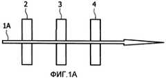
Фиг.1 схематически иллюстрирует два общих варианта осуществления оптической компоновки;1 schematically illustrates two general embodiments of an optical arrangement;
Фиг.2 иллюстрирует спектральные характеристики для компоновки на Фиг.1В вместе со спектром красителя Су5;Figure 2 illustrates the spectral characteristics for the arrangement in Figure 1B together with the spectrum of the dye Cy5;
Фиг.3 иллюстрирует вариант осуществления способа обнаружения присутствия целевой молекулы в образце;Figure 3 illustrates an embodiment of a method for detecting the presence of a target molecule in a sample;
Фиг.4 показывает график зависимости показателя преломления, n, водных растворов сахарозы от весового процентного содержания, р.Figure 4 shows a graph of the dependence of the refractive index, n, of aqueous solutions of sucrose from the weight percentage, p.
Описание вариантов осуществленияDescription of Embodiments
В биологическом исследовании и медицинской диагностике многие биомаркеры детектируют с помощью присоединенной флуоресцентной метки. Обычно используемое устройство представляет собой флуоресцентный сканер или микроскоп, но для особенных вариантов применения делают специализированное оборудование на основе тех же принципов детектирования.In biological research and medical diagnostics, many biomarkers are detected using an attached fluorescence tag. A commonly used device is a fluorescence scanner or microscope, but for special applications specialized equipment is made based on the same principles of detection.
В общем варианте осуществления настоящего изобретения применяют оптическую компоновку, где использованы по меньшей мере два спектральных фильтра. Фиг.1 схематически иллюстрирует два общих варианта осуществления. Фиг.1А показывает схематическую иллюстрацию устройства регистрации флуоресценции в режиме пропускания, где полученный пучок пропускается через субстрат, тогда как Фиг.1В показывает схематическую иллюстрацию устройства регистрации флуоресценции в режиме отражения, где полученный пучок отражается от субстрата. На Фиг. 1А и 1В световой пучок 1А, 1В испускается в сторону субстрата 3. Чтобы отделить полученный флуоресцентный световой пучок от облучающего нефлуоресцентного света, используют спектральные фильтры.In a general embodiment of the present invention, an optical arrangement is used wherein at least two spectral filters are used. 1 schematically illustrates two general embodiments. FIG. 1A shows a schematic illustration of a transmission mode fluorescence recording apparatus where a received beam is passed through a substrate, while FIG. 1B shows a schematic illustration of a reflection mode fluorescence recording apparatus where a received beam is reflected from a substrate. In FIG. 1A and 1B, the
Действие спектрального фильтра состоит из двух стадий: первый фильтр 2 излучения (называемый «фильтром возбуждающего излучения») устанавливают на маршруте пучка между источником излучения (света) и субстратом. Фильтр возбуждающего излучения предпочтительно пропускает лучи с длиной волны, перекрывающейся со спектром возбуждения метки, и блокирует все лучи с длиной волны, которая находится в пределах спектра интервала детектирования. Второй фильтр 4 излучения (называемый «фильтром испускания» или, альтернативно, «фильтром детектирования») вводят в маршрут пучка, фильтр испускания предпочтительно блокирует или по меньшей мере значительно подавляет облучающее излучение и пропускает только излучение флуоресценции. Коэффициент ослабления (эффективность блокирования) типичного набора фильтров составляет лучше чем 10-6.The action of the spectral filter consists of two stages: the first radiation filter 2 (called the "excitation radiation filter") is installed on the beam path between the radiation source (light) and the substrate. The excitation filter preferably transmits rays with a wavelength that overlaps with the excitation spectrum of the mark, and blocks all rays with a wavelength that is within the spectrum of the detection interval. A second radiation filter 4 (called an "emission filter" or, alternatively, a "detection filter") is introduced into the beam path, the emission filter preferably blocks or at least significantly suppresses the irradiation radiation and only transmits fluorescence radiation. The attenuation coefficient (blocking efficiency) of a typical filter set is better than 10-6 .
Кроме того, на Фиг.1В применяется светоделитель 5, светоделитель может быть использован, например, в ситуации, где субстрат является непрозрачным. В альтернативном варианте осуществления вместо светоделителя может быть применено дихроичное зеркало, дихроичное зеркало отражает возбуждающий свет с длиной волны ниже определенного значения и пропускает свет с длиной волны выше этого значения. Дихроичное зеркало поэтому может также действовать как фильтр 4 испускания, но все же отдельный фильтр испускания может быть применен для повышения эффективности, но это может не понадобиться.In addition, in FIG. 1B, a
В варианте осуществления субстрат может быть облучен несколькими мощными светодиодами (LED), такими как от 2 до 10 красных светодиодов (LED), может быть использована компоновка затемненного поля. Полученный свет регистрируют цифровой CCD-камерой (не показана) с фильтром испускания, размещенным перед камерой. В качестве примера флуорофора может быть использован флуоресцентный цианиновый краситель Су5.In an embodiment, the substrate may be irradiated with several high-power light emitting diodes (LEDs), such as 2 to 10 red light emitting diodes (LEDs), a dark field arrangement may be used. The resulting light is recorded by a digital CCD camera (not shown) with an emission filter placed in front of the camera. As an example of a fluorophore, a Cy5 fluorescent cyanine dye can be used.
Субстрат 3 может быть приготовлен любым подходящим способом приготовления субстрата, такого как субстрат биочипа для применения в биотестировании. Один типичный способ тестирования на чипе включает иммобилизацию зондовых молекул в отдельных местах на субстрате. Раствор, содержащий целевые молекулы, которые связываются с присоединенными зондами, приводят в контакт со связанными зондами в условиях, достаточных для стимулирования связывания целей в растворе с комплементарными зондами на субстрате, с образованием фиксированного комплекса, который связан с поверхностью субстрата. Биочип может иметь размеры в микрометровом диапазоне или даже в миллиметровом диапазоне. Число различных пятен с различающимися характеристиками гибридизации на биочипе может варьировать от около 1 до 1000 на мм2 на данном чипе, и даже больше, например, вплоть до 106 пятен на мм2. Как правило, внутри пятна на чипе иммобилизованы идентичные зондовые молекулы.
Фиг.2 иллюстрирует вариант осуществления возможных спектральных характеристик, задействованных в компоновке на Фиг.1В, вместе со спектром красителя Су5. Фиг.2 скомпонована с использованием онлайн-приложения Curv-o-matic, доступного из веб-сайта Omega Optical (www.omegafilters.com). Фиг.2 показывает пропускание, Т, в процентах, как функцию длины волны, λ, в нанометрах, включенных спектров, для набора фильтров Omega XF110-2.FIG. 2 illustrates an embodiment of possible spectral characteristics involved in the arrangement of FIG. 1B, together with a spectrum of dye Cy5. Figure 2 is configured using the Curv-o-matic online application available from the Omega Optical website (www.omegafilters.com). Figure 2 shows the transmittance, T, in percent, as a function of wavelength, λ, in nanometers, of the included spectra, for the Omega XF110-2 filter set.
Фиг.2 показывает спектр 20 возбуждения красителя Су5, имеющий пиковую длину волны возбуждения при 649 нм, вместе с соответствующим спектром 21 испускания, имеющим пиковую длину волны испускания при 670 нм. Разность между длиной волны облучающего излучения и длиной волны флуоресценции, на фотон, называется «стоксовским сдвигом». Стоксовский сдвиг для красителя Су5 составляет 21 нм.2 shows an
Фильтр возбуждения представляет собой фильтр возбуждения Omega 630AF50, характеризующийся спектром, обозначенным номером 22 (ширина полосы 50 нм с центром при 630 нм). Фильтр испускания представляет собой фильтр испускания Omega 695AF55, характеризующийся спектром, обозначенным номером 23 (ширина полосы 55 нм с центром при 695 нм). Дихроичное зеркало выбрано так, что спектр зеркала, обозначенный как 24, таковой, что оно отражает падающий свет при длине волны возбуждающего излучения, в то же время пропуская полученный свет со стоксовским сдвигом. Конкретный набор фильтров и дихроичное зеркало приведены в качестве примера и могут быть необязательно использованы во всех вариантах осуществления. Например, как упомянуто в связи с Фиг.1В, можно обойтись без фильтра испускания, когда применяется дихроичное зеркало.The excitation filter is an Omega 630AF50 excitation filter, characterized by a spectrum indicated by number 22 (bandwidth of 50 nm centered at 630 nm). The emission filter is an Omega 695AF55 emission filter, characterized by a spectrum indicated by number 23 (bandwidth 55 nm centered at 695 nm). The dichroic mirror is chosen so that the spectrum of the mirror, designated as 24, is such that it reflects the incident light at a wavelength of the exciting radiation, while at the same time passing the received light with a Stokes shift. A specific filter set and dichroic mirror are exemplary and may optionally be used in all embodiments. For example, as mentioned in connection with FIG. 1B, an emission filter can be dispensed with when a dichroic mirror is applied.
Таблица показывает результаты эксперимента, в котором оптические характеристики были измерены на пористых найлоновых субстратах 3 (Nytran N и Nytran SPC). Эксперимент проводили путем облучения субстрата с длиной волны падающего света 650 нм и последующего детектирования пучка, полученного от субстрата. Были проведены два типа экспериментов, один с сухим субстратом, и один, в котором субстрат был подвергнут воздействию воды на стадии промывания.The table shows the results of an experiment in which optical characteristics were measured on porous nylon substrates 3 (Nytran N and Nytran SPC). The experiment was carried out by irradiating a substrate with an incident light wavelength of 650 nm and then detecting a beam obtained from the substrate. Two types of experiments were conducted, one with a dry substrate, and one in which the substrate was exposed to water in the washing step.
Как можно видеть в таблице, субстрат имеет очень высокую отражательную способность, в особенности, будучи в сухом состоянии. Причина этой высокой отражательной способности состоит в рассеянии вследствие высокой пористости субстрата. Степень рассеяния зависит от разности между показателями преломления воздуха и субстрата. По сравнению с воздухом показатель воды является гораздо более близким к показателю субстрата. Это является причиной того, почему влажный субстрат проявляет более низкое отражение, чем сухой субстрат.As can be seen in the table, the substrate has a very high reflectivity, especially when dry. The reason for this high reflectivity is scattering due to the high porosity of the substrate. The degree of scattering depends on the difference between the refractive indices of the air and the substrate. Compared to air, the water rate is much closer to the substrate. This is the reason why the wet substrate exhibits lower reflection than the dry substrate.
В соответствии с настоящим изобретением во время стадии промывания в ходе анализа употребляется жидкость с по существу согласованным показателем, и тем самым отражательная способность субстрата может быть значительно снижена, с сокращением до типичного значения 5% коэффициента отражения.In accordance with the present invention, a liquid with a substantially consistent index is used during the washing step during the analysis, and thereby the reflectivity of the substrate can be significantly reduced, with a reduction to a typical 5% reflection coefficient.
Интенсивность возбуждения может быть увеличена по меньшей мере в 3 раза по сравнению с водой в качестве промывной жидкости, но может быть повышена в 20 раз по сравнению с сухим субстратом.The excitation intensity can be increased at least 3 times compared with water as a wash liquid, but can be increased 20 times compared with a dry substrate.
Соотношение между возбуждающим излучением и флуоресцентным излучением может быть улучшено по меньшей мере в 14 раз, если сравнивать с водой, и может быть повышено в 19 раз по сравнению с сухим субстратом.The ratio between the exciting radiation and the fluorescent radiation can be improved by at least 14 times, when compared with water, and can be increased by 19 times compared to a dry substrate.
Фиг.3 иллюстрирует вариант осуществления способа обнаружения присутствия целевой молекулы в образце в соответствии с настоящим изобретением, где биочип приготовлен с использованием стадии промывания. Фиг. 3А-3С иллюстрируют по меньшей мере некоторые из примененных стадий.Figure 3 illustrates an embodiment of a method for detecting the presence of a target molecule in a sample in accordance with the present invention, where the biochip is prepared using a washing step. FIG. 3A-3C illustrate at least some of the steps used.
В стадиях, предшествующих стадии из Фиг.3А, приготовили образец жидкости с целевыми биомолекулами, конъюгированными с флуорофорами. На стадии 37 на Фиг.3А образец 6 контактирует с субстратом 30 путем протекания образца жидкости через субстрат, обеспечивая присоединение целевых биомолекул, имеющих флуорофоры, к специфическим местам связывания на субстрате. Должно быть понятно, что целевые молекулы могут контактировать с субстратом альтернативными путями, например, путем нанесения капель из импульсного распылителя или другим пригодным способом.In the steps preceding the step of FIG. 3A, a fluid sample was prepared with target biomolecules conjugated to fluorophores. In
Можно предполагать, что во время стадий приготовления не все флуорофоры будут связываться с зондовой молекулой. Это значит, что в дополнение к флуорофорам, которые связались с субстратом 30, есть также несвязанные флуорофоры, которые не присоединены к субстрату, но все еще присутствуют. Стадия 38 промывания применяется для удаления или по меньшей мере разбавления любых несвязанных флуорофорных конъюгатов, с оставлением в результате только связанных на субстрате флуорофорных конъюгатов, как иллюстрировано на Фиг.3В. Во время этой стадии промывную жидкость 7 продавливают через субстрат 31. В настоящем изобретении промывную жидкость 7 выбирают так, что она имеет показатель преломления промывной жидкости, по существу согласованный с показателем преломления субстрата 31.It can be assumed that during the preparation stages not all fluorophores will bind to the probe molecule. This means that in addition to the fluorophores that bind to the
Фиг.3 иллюстрирует стадию 39 детектирования, чтобы зарегистрировать присутствие полученных присоединенных комплексов на субстрате, стадия детектирования была описана в связи с Фиг.1. Поскольку во время стадии промывания (Фиг.3В) употребляли жидкость с по существу согласованным показателем, отражательная способность субстрата 32 была существенно снижена, увеличивая чувствительность стадии детектирования. Детектирование типично проводят непосредственно после стадии промывания так, что субстрат все еще является влажным.FIG. 3 illustrates a
В различных вариантах осуществления настоящего изобретения могут быть использованы различные жидкости с согласованным показателем. В одном варианте осуществления может быть применено масло, в качестве примера пригодного масла может быть использовано масло Zeiss Immersol 518F, с n=1,518 при температуре 23ºС. В других вариантах осуществления могут быть употреблены водные растворы плотных материалов. В конкретном варианте осуществления употребляется водный раствор сахара. Может быть предпочтительным применение 60%-70%-го раствора сахара (сахарозы и т.д.), тем самым достигая показателя преломления 1,45 (см. Фиг.4, иллюстрирующую показатель преломления, n, водных растворов сахарозы как функцию весового процентного содержания, р). Водные растворы сахарозы могут представлять собой предпочтительную жидкость для согласования показателя, поскольку флуорофорные конъюгаты легко растворяются в такой жидкости, делая жидкость пригодной как для стадии промывания, так и для стадии детектирования.In various embodiments, the implementation of the present invention can be used in various liquids with a consistent indicator. In one embodiment, an oil may be used; as an example of a suitable oil, Zeiss Immersol 518F oil may be used, with n = 1.518 at a temperature of 23 ° C. In other embodiments, aqueous solutions of dense materials may be used. In a specific embodiment, an aqueous sugar solution is used. It may be preferable to use a 60% -70% sugar solution (sucrose, etc.), thereby achieving a refractive index of 1.45 (see Figure 4, illustrating the refractive index, n, of aqueous sucrose solutions as a function of weight percent content, p). Aqueous solutions of sucrose may be the preferred fluid for consistency, since fluorophore conjugates readily dissolve in such a fluid, making the fluid suitable for both the washing step and the detection step.
Должно быть понятно, что в альтернативном варианте осуществления могут быть применены дополнительные стадии промывания. Такие дополнительные стадии промывания могут быть использованы с отличающимися от таковой промывными жидкостями, в ситуации, где для различных стадий промывания употребляются различные промывные жидкости, по меньшей мере последнюю стадию промывания проводят с использованием промывной жидкости с показателем преломления, по существу согласованным с таковым для субстрата.It should be clear that in an alternative embodiment, additional washing steps can be applied. Such additional washing steps can be used with different washing liquids in a situation where different washing liquids are used for different washing stages, at least the last washing stage is carried out using a washing liquid with a refractive index substantially consistent with that of the substrate.
Стадии на Фиг. 3 и возможные дополнительные стадии могут быть выполнены, возможно, в автоматическом или полуавтоматическом режиме, в устройстве для получения анализируемого образца и/или системе оптического детектирования. Такие устройства и системы могут включать блок 33 обработки для принятия субстрата, и блок 34 промывания для выполнения стадии промывания на субстрате. Блок обработки и блок промывания могут быть исполнены в одном и том же агрегате, или образец может перемещаться между блоками. Варианты осуществления систем оптического детектирования также включают источник 36 излучения, такой как один или более лазерных диодов, и детектор 35 излучения, такой как CCD-камера.The stages in FIG. 3 and possible additional steps can be performed, possibly in an automatic or semi-automatic mode, in a device for obtaining an analyzed sample and / or an optical detection system. Such devices and systems may include a
Представлены также наборы для применения в тестах с детектированием целей. Наборы по меньшей мере включают промывную жидкость, причем промывную жидкость с показателем, по существу согласованным с субстратом, и инструкции по применению промывной жидкости. Наборы могут далее включать один или более дополнительных компонентов, употребляемых когда проводится тест с детектированием целей, таких как один или более субстратов, реагенты для приготовления образца, буферы, метки и т.д. Инструкции по применению могут быть выполнены в бумажном формате, записаны на подходящем носителе информации, приведены в форме указаний, как найти инструкции в удаленном источнике, например в интернете, и т.д.Kits for use in target detection tests are also provided. The kits at least include a washing liquid, wherein the washing liquid with an index substantially consistent with the substrate and instructions for using the washing liquid. Kits may further include one or more additional components used when testing with detection targets, such as one or more substrates, sample preparation reagents, buffers, tags, etc. Instructions for use can be executed in paper format, recorded on a suitable storage medium, given in the form of instructions on how to find instructions in a remote source, for example on the Internet, etc.
Хотя настоящее изобретение было описано в связи с конкретными вариантами осуществления, оно не предполагается быть ограниченным изложенной здесь конкретной формой. Скорее рамки настоящего изобретения ограничиваются только прилагаемыми пунктами формулы изобретения. В пунктах формулы изобретения термин «включающий» не исключает присутствия других элементов или стадий. Дополнительно, хотя отдельные признаки могут быть включены в различные пункты формулы изобретения, таковые преимущественно могут быть по возможности скомбинированы, и включение в различные пункты формулы изобретения не подразумевает, что комбинация признаков ненадежна и/или неблагоприятна. В дополнение, упоминания в единственном числе не исключают множественного числа. Так, упоминания единственного числа, «первый», «второй» и т.д. не исключают множества. Далее, кодовые обозначения в пунктах формулы изобретения не должны толковаться как ограничения рамок изобретения.Although the present invention has been described in connection with specific embodiments, it is not intended to be limited to the specific form set forth herein. Rather, the scope of the present invention is limited only by the attached claims. In the claims, the term “comprising” does not exclude the presence of other elements or steps. Additionally, although individual features may be included in various claims, they may advantageously be combined as much as possible, and inclusion in various claims does not imply that the combination of features is unreliable and / or unfavorable. In addition, singular references do not exclude the plural. So, singular references, “first”, “second”, etc. do not exclude the multitude. Further, the code symbols in the claims should not be construed as limiting the scope of the invention.
Claims (8)
Translated fromRussian(a) приведение образца (37) в контакт с субстратом, имеющим иммобилизованные на нем зондовые молекулы, которые специфически связываются с целевой молекулой;
(b) промывание субстрата (38) на стадии промывания промывной жидкостью для удаления или разбавления несвязанных целевых молекул;
(c) обнаружение присутствия полученных связанных комплексов (39) на субстрате для определения, присутствует ли люминесцентно меченная целевая молекула в образце;
в котором субстрат облучают пучком излучения и далее регистрируют полученный пучок люминесценции от субстрата, и присутствие люминесцентно меченных целевых молекул обнаруживают путем регистрации люминесценции люминесцентно меченных целевых молекул, отличающийся тем, что регистрация полученного пучка люминесценции от субстрата происходит в присутствии промывной жидкости, где показатель преломления промывной жидкости находится в диапазоне от показателя преломления субстрата плюс 10% до показателя преломления субстрата минус 10%.1. A method for detecting the presence of a luminescently labeled target molecule in a sample, comprising:
(a) bringing the sample (37) into contact with a substrate having probe molecules immobilized on it that specifically bind to the target molecule;
(b) washing the substrate (38) in the washing step with a washing liquid to remove or dilute unbound target molecules;
(c) detecting the presence of the resulting coupled complexes (39) on a substrate to determine if a luminescently labeled target molecule is present in the sample;
in which the substrate is irradiated with a radiation beam and then the resulting luminescence beam from the substrate is recorded, and the presence of luminescently labeled target molecules is detected by detecting the luminescence of luminescently labeled target molecules, characterized in that the registration of the obtained luminescence beam from the substrate occurs in the presence of a wash liquid, where the refractive index of the wash the liquid is in the range from the refractive index of the substrate plus 10% to the refractive index of the substrate minus 10%.
Applications Claiming Priority (2)
| Application Number | Priority Date | Filing Date | Title |
|---|---|---|---|
| EP06122797 | 2006-10-24 | ||
| EP06122797.1 | 2006-10-24 |
Publications (2)
| Publication Number | Publication Date |
|---|---|
| RU2009119452A RU2009119452A (en) | 2010-11-27 |
| RU2446402C2true RU2446402C2 (en) | 2012-03-27 |
Family
ID=38993313
Family Applications (1)
| Application Number | Title | Priority Date | Filing Date |
|---|---|---|---|
| RU2009119452/15ARU2446402C2 (en) | 2006-10-24 | 2007-10-19 | Detection of target molecules in sample |
Country Status (9)
| Country | Link |
|---|---|
| US (2) | US10101321B2 (en) |
| EP (1) | EP2076773B1 (en) |
| JP (1) | JP2010507796A (en) |
| CN (1) | CN101548186A (en) |
| AT (1) | ATE493654T1 (en) |
| BR (1) | BRPI0717393A2 (en) |
| DE (1) | DE602007011651D1 (en) |
| RU (1) | RU2446402C2 (en) |
| WO (1) | WO2008050274A1 (en) |
Cited By (1)
| Publication number | Priority date | Publication date | Assignee | Title |
|---|---|---|---|---|
| RU2769999C2 (en)* | 2017-12-28 | 2022-04-14 | Адор Диагностикс С.Р.Л | Electrophoretic chip and method for fast detection of the presence of target nucleic acid molecules |
Families Citing this family (9)
| Publication number | Priority date | Publication date | Assignee | Title |
|---|---|---|---|---|
| US20100247446A1 (en)* | 2009-03-24 | 2010-09-30 | Olympus Corporation | Method and system for analyzing optical signal |
| WO2013036102A1 (en) | 2011-09-08 | 2013-03-14 | N.V. Nutricia | Use of infant formula with cholesterol |
| WO2013036103A1 (en) | 2011-09-08 | 2013-03-14 | N.V. Nutricia | Use of infant formula with large lipid globules |
| WO2015069726A1 (en)* | 2013-11-08 | 2015-05-14 | X-Machine Rx, Inc. | Selection apparatus and methods |
| JP6568949B2 (en) | 2015-03-11 | 2019-08-28 | オンテラ インコーポレイテッド | Nanopore detection method for small molecules by competitive assay |
| US9983191B2 (en) | 2015-03-11 | 2018-05-29 | Two Pore Guys, Inc. | Nanopore detection of small molecules through competition assays |
| US10048256B2 (en) | 2015-03-18 | 2018-08-14 | Bio-Rad Laboratories, Inc. | Sample analysis systems and methods |
| FI20205546A1 (en)* | 2020-05-27 | 2021-11-28 | Kxs Tech Oy | An optically transparent window assembly for detachable connection to a refractometer |
| CN112147186B (en)* | 2020-09-23 | 2023-07-18 | 深圳市科曼医疗设备有限公司 | Specific protein analysis method and control device based on blood cell analyzer |
Citations (2)
| Publication number | Priority date | Publication date | Assignee | Title |
|---|---|---|---|---|
| WO1993003347A1 (en)* | 1991-07-26 | 1993-02-18 | Cirrus Diagnostics, Inc. | Automated immunoassay analyzer |
| US20030174992A1 (en)* | 2001-09-27 | 2003-09-18 | Levene Michael J. | Zero-mode metal clad waveguides for performing spectroscopy with confined effective observation volumes |
Family Cites Families (17)
| Publication number | Priority date | Publication date | Assignee | Title |
|---|---|---|---|---|
| IT1079045B (en)* | 1977-05-16 | 1985-05-08 | Syva Co | DOUBLE RECEPTOR FLUORESCENT IMUUNOLOGICAL ANALYSIS |
| GB2016687B (en) | 1978-03-20 | 1982-09-08 | Abbott Lab | Sugar coated reagents for solid phase immunoassay |
| EP0153875A3 (en) | 1984-03-01 | 1987-06-24 | The State Of Victoria | Enzyme-linked immunosorbent assay method and test kit |
| GB8423204D0 (en)* | 1984-09-14 | 1984-10-17 | Comtech Res Unit | Assay technique and equipment |
| US4775619A (en)* | 1984-10-16 | 1988-10-04 | Chiron Corporation | Polynucleotide determination with selectable cleavage sites |
| JPS61272659A (en)* | 1985-05-29 | 1986-12-02 | Hitachi Ltd | Fluorescent immunoassay method |
| US6498037B1 (en)* | 1991-03-04 | 2002-12-24 | Bayer Corporation | Method of handling reagents in a random access protocol |
| US5807756A (en)* | 1995-01-10 | 1998-09-15 | At Point Bio | Ceramic assembly for use in biological assays |
| US5959098A (en) | 1996-04-17 | 1999-09-28 | Affymetrix, Inc. | Substrate preparation process |
| US6150147A (en) | 1998-02-06 | 2000-11-21 | Affymetrix, Inc. | Biological array fabrication methods with reduction of static charge |
| US6239871B1 (en)* | 1999-08-24 | 2001-05-29 | Waters Investments Limited | Laser induced fluorescence capillary interface |
| US7635571B2 (en)* | 2000-12-07 | 2009-12-22 | Siemens Healthcare Diagnostics Products Gmbh | Amplified signal in binding assays |
| JP3968425B2 (en) | 2002-11-13 | 2007-08-29 | 独立行政法人産業技術総合研究所 | Method of introducing light into optical waveguide and optical waveguide spectrometer using the same |
| US20050048571A1 (en) | 2003-07-29 | 2005-03-03 | Danielson Paul S. | Porous glass substrates with reduced auto-fluorescence |
| US20080227188A1 (en)* | 2005-10-03 | 2008-09-18 | Koninklijke Philips Electronics, N.V. | Biosensor with Optically Matched Substrate |
| EP1966596B1 (en) | 2005-12-22 | 2018-04-11 | Koninklijke Philips N.V. | Luminescence sensor operating in reflection mode |
| WO2007072418A2 (en)* | 2005-12-22 | 2007-06-28 | Koninklijke Philips Electronics N.V. | Increasing energy density in sub-wavelength wire-grids |
- 2007
- 2007-10-19CNCNA2007800396844Apatent/CN101548186A/enactivePending
- 2007-10-19EPEP07826802Apatent/EP2076773B1/enactiveActive
- 2007-10-19BRBRPI0717393-8Apatent/BRPI0717393A2/enactiveIP Right Grant
- 2007-10-19USUS12/446,461patent/US10101321B2/enactiveActive
- 2007-10-19DEDE602007011651Tpatent/DE602007011651D1/enactiveActive
- 2007-10-19JPJP2009534001Apatent/JP2010507796A/enactivePending
- 2007-10-19WOPCT/IB2007/054266patent/WO2008050274A1/enactiveApplication Filing
- 2007-10-19RURU2009119452/15Apatent/RU2446402C2/enactive
- 2007-10-19ATAT07826802Tpatent/ATE493654T1/ennot_activeIP Right Cessation
- 2017
- 2017-09-21USUS15/710,887patent/US10670589B2/enactiveActive
Patent Citations (2)
| Publication number | Priority date | Publication date | Assignee | Title |
|---|---|---|---|---|
| WO1993003347A1 (en)* | 1991-07-26 | 1993-02-18 | Cirrus Diagnostics, Inc. | Automated immunoassay analyzer |
| US20030174992A1 (en)* | 2001-09-27 | 2003-09-18 | Levene Michael J. | Zero-mode metal clad waveguides for performing spectroscopy with confined effective observation volumes |
Cited By (1)
| Publication number | Priority date | Publication date | Assignee | Title |
|---|---|---|---|---|
| RU2769999C2 (en)* | 2017-12-28 | 2022-04-14 | Адор Диагностикс С.Р.Л | Electrophoretic chip and method for fast detection of the presence of target nucleic acid molecules |
Also Published As
| Publication number | Publication date |
|---|---|
| US10670589B2 (en) | 2020-06-02 |
| CN101548186A (en) | 2009-09-30 |
| JP2010507796A (en) | 2010-03-11 |
| EP2076773A1 (en) | 2009-07-08 |
| US20180074047A1 (en) | 2018-03-15 |
| WO2008050274A1 (en) | 2008-05-02 |
| US20100197515A1 (en) | 2010-08-05 |
| ATE493654T1 (en) | 2011-01-15 |
| EP2076773B1 (en) | 2010-12-29 |
| BRPI0717393A2 (en) | 2013-10-15 |
| US10101321B2 (en) | 2018-10-16 |
| RU2009119452A (en) | 2010-11-27 |
| DE602007011651D1 (en) | 2011-02-10 |
Similar Documents
| Publication | Publication Date | Title |
|---|---|---|
| RU2446402C2 (en) | Detection of target molecules in sample | |
| US7076092B2 (en) | High-throughput, dual probe biological assays based on single molecule detection | |
| JP3535174B2 (en) | Biospecificity assay | |
| JP5877155B2 (en) | Method for detecting dilute particles in solution using luminescent probe | |
| US7961315B2 (en) | Fluorescence detection enhancement using photonic crystal extraction | |
| US6589438B2 (en) | Method for making microsensor arrays for detecting analytes | |
| JP5652393B2 (en) | Plasmon excitation sensor and assay method used for measurement method by SPFS-LPFS system | |
| CN108474743B (en) | Optical detection of substances in fluids | |
| JP2000515966A (en) | Apparatus and method for performing a quantitative fluorescent mark affinity test | |
| JP5428322B2 (en) | Assay method using plasmon excitation sensor | |
| US20210208075A1 (en) | Autofluorescence quenching assay and device | |
| EP1797195B1 (en) | Method and apparatus for the detection of labeling elements in a sample | |
| US7312867B2 (en) | Method and device for the detection of at least one luminescent substance | |
| WO2014188620A1 (en) | Sensor and test method | |
| CN101387637A (en) | Biological rapid detection system | |
| JP2008215823A (en) | Fluorescent sensor | |
| JP5298877B2 (en) | Assay method using plasmon excitation sensor | |
| JP7203034B2 (en) | Analyte detection method | |
| JP2024002206A (en) | Material separation device, analyzer, and method for analysis | |
| JP5298876B2 (en) | Plasmon excitation sensor and assay method using the same | |
| JP2005180963A (en) | Optical analyzer |