RU2438070C1 - Fuel combustion monitoring and control method in piston-type engine, and device for its implementation - Google Patents
Fuel combustion monitoring and control method in piston-type engine, and device for its implementationDownload PDFInfo
- Publication number
- RU2438070C1 RU2438070C1RU2010135626/07ARU2010135626ARU2438070C1RU 2438070 C1RU2438070 C1RU 2438070C1RU 2010135626/07 ARU2010135626/07 ARU 2010135626/07ARU 2010135626 ARU2010135626 ARU 2010135626ARU 2438070 C1RU2438070 C1RU 2438070C1
- Authority
- RU
- Russia
- Prior art keywords
- ion current
- fuel
- engine
- electrodes
- combustion
- Prior art date
Links
Images
Landscapes
- Combined Controls Of Internal Combustion Engines (AREA)
Abstract
Description
Translated fromRussianИзобретение относится к системам контроля и управления процессами воспламенения и сгорания топлива, конкретно к системам контроля и управления процесса сгорания углеводородного топлива в камерах сгорания ДВС.The invention relates to systems for monitoring and controlling the processes of ignition and combustion of fuel, specifically to systems for monitoring and controlling the process of combustion of hydrocarbon fuel in the combustion chambers of an internal combustion engine.
Наиболее близким по технической сущности и достигаемому эффекту является способ контроля и управления сгоранием топлива путем измерения и сравнения с эталонным значением ионного тока в пламени и регулирования подачи топлива, причем измерение и сравнение между собой величин ионного тока производят в зоне завершения сгорания топлива, поддерживая отношение величины измеренного ионного тока к величине ионного тока при коэффициенте избытка воздуха α, равном единице, в диапазоне 0,6-0,75. Ионизационный датчик содержит два изолированных друг от друга электрода, одним из которых является камера сгорания двигателя, причем с целью измерения ионного тока в зоне завершения сгорания топлива второй электрод, изолированный от камеры сгорания металлический стержень, устанавливается в наиболее удаленной от свечи зажигания зоне камеры сгорания (патент РФ №2309334, F23N 5/12, дата публикации 27.10.2007, патентообладатель Тольяттинский государственный университет).The closest in technical essence and the achieved effect is a method of monitoring and controlling the combustion of fuel by measuring and comparing with the reference value of the ion current in the flame and regulating the fuel supply, moreover, the measurement and comparison of the values of the ion current are carried out in the zone of completion of fuel combustion, maintaining the ratio of measured ion current to the ion current when the coefficient of excess air α equal to unity in the range of 0.6-0.75. The ionization sensor contains two electrodes isolated from each other, one of which is the combustion chamber of the engine, and in order to measure the ion current in the zone of completion of fuel combustion, the second electrode, a metal rod isolated from the combustion chamber, is installed in the zone of the combustion chamber farthest from the spark plug ( RF patent No. 2309334, F23N 5/12, publication date 10.27.2007, patent holder of Togliatti State University).
Недостаток известного технического решения заключается в том, что кпд при сгорании топлива относительно низко.A disadvantage of the known technical solution is that the efficiency in fuel combustion is relatively low.
Задачей, на решение которой направлено заявляемое техническое решение, является повышение кпд при работе двигателя.The task to which the claimed technical solution is directed is to increase the efficiency during engine operation.
Технический результат заключается в повышении эксплуатационных характеристик.The technical result is to increase operational characteristics.
Технический результат достигается тем, что в способе контроля и управления сжигания топлива в поршневом двигателе, включающем в себя регистрацию высоковольтного сигнала с электродов свечи зажигания, момента появления, существования и исчезновения сигнала ионного тока на отдельном электроде ионизационного датчика, проводят сравнение времени появления, существования и исчезновения ионного тока на отдельном электроде, вычисляют скорость распространения в основной и заключительной фазах сгорания делением расстояния от свечи зажигания на промежуток времени от искрового разряда на электродах свечи зажигания до возникновения или исчезновения ионного тока на отдельном электроде или путем деления расстояния между изолированными электродами на время существования ионного тока на отдельном электроде, а интенсивность протекания скоростей химических реакций сгорания определяют сравнением величины ионного тока при работе двигателя на любом составе топливовоздушной смеси с величиной ионного тока при работе на стехиометрическом составе топливовоздушной смеси.The technical result is achieved by the fact that in the method of monitoring and controlling the combustion of fuel in a piston engine, which includes recording a high voltage signal from the electrodes of the spark plug, the moment of appearance, existence and disappearance of the ion current signal on a separate electrode of the ionization sensor, a comparison of the time of appearance, existence and the disappearance of ion current on a separate electrode, calculate the propagation velocity in the main and final phases of combustion by dividing the distance from the spark plug for the period from the spark discharge on the electrodes of the spark plug to the appearance or disappearance of the ion current on the separate electrode or by dividing the distance between the isolated electrodes by the time the ion current exists on the separate electrode, and the intensity of the rates of chemical combustion reactions is determined by comparing the magnitude of the ion current during engine operation on any composition of the air-fuel mixture with an ion current when working on the stoichiometric composition of the air-fuel mixture.
Устройство для контроля и управления сжиганием топлива в поршневом двигателе, включающее полость изменяемого объема цилиндра, поршень, головку цилиндра с установленной в нее свечой зажигания и комплексом ионизационных датчиков, одним из электродов которого является корпус двигателя, имеет комплекс ионизационных датчиков, который содержит не менее восьми изолированных от деталей корпуса двигателей электродов, расположенных по окружности на расстоянии, диаметрально противоположном друг другу в изделии, которое также служит прокладкой между головкой цилиндра и корпусом двигателя.A device for monitoring and controlling the combustion of fuel in a piston engine, including a cavity of variable cylinder volume, a piston, a cylinder head with a spark plug installed in it and a complex of ionization sensors, one of the electrodes of which is the engine body, has a complex of ionization sensors, which contains at least eight insulated from parts of the motor housing of electrodes located around a circle at a distance diametrically opposite to each other in the product, which also serves as a gasket between the cylinder head and the motor housing.
Конструкция заявляемого технического решения показана на чертежах, где на:The design of the proposed technical solution is shown in the drawings, where:
фиг.1 показано устройство для контроля и управления сжиганием топлива в поршневом двигателе, вид сверху;figure 1 shows a device for monitoring and control of fuel combustion in a piston engine, top view;
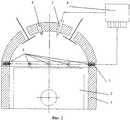
фиг.2 показано устройство для контроля и управления сжиганием топлива в поршневом двигателе, в разрезе.figure 2 shows a device for monitoring and controlling the combustion of fuel in a piston engine, in section.
Заявляемое техническое решение может быть реализовано в конструкции устройства для контроля и управления сжиганием топлива в поршневом двигателе, включающем цилиндр 1, поршень 2, форсунку 3, свечку зажигания 4, ионизационные датчики 5, корпус двигателя 6, прокладку 7, электронный блок управления 8.The claimed technical solution can be implemented in the design of a device for monitoring and controlling fuel combustion in a piston engine, including
Устройство для контроля и управления сжиганием топлива в поршневом двигателе устроено следующим образом.A device for monitoring and controlling the combustion of fuel in a piston engine is arranged as follows.
Ионизационные датчики 5 в количестве не менее шести, содержащие несколько изолированных друг от друга электродов, один из которых, отрицательный, - окантовка прокладки 7 головки блока цилиндра 1 (корпус двигателя 6), другие, положительные, - изолированные от корпуса двигателя металлические стержни (ионизационные датчики 5), устанавливаются в прокладку 7 головки блока цилиндра 1 по окружности таким образом, что ионизационные датчики 5 находятся на диаметрально противоположном расстоянии друг от друга.
Устройство для контроля и управления сжиганием топлива в поршневом двигателе работает следующим образом.A device for monitoring and controlling the combustion of fuel in a piston engine operates as follows.
В электронный блок управления 8 ДВС закладывается «эталонный» сигнал, который для различных скоростных и нагрузочных режимах различен. Данный «эталонный» сигнал соответствует работе ДВС при минимальной токсичности отработавших газов и наилучшей топливной экономичности. Протекание процесса сгорания регистрируется ионизационными датчиками 5, а информационным параметром является величина средней скорости распространения фронта пламени, изменение которой влечет за собой изменение процесса сгорания. В процессе сгорания фронт пламени, достигнув положительного электрода - металлического стержня (ионизационные датчики 5), замыкает электрическую цепь между электродами ионизационного датчика 5, окантовкой прокладки 7 головки блока цилиндра 1 (корпус двигателя 6) и металлическими стержнями (ионизационные датчики 5), в которой появляется ионный ток. Зарегистрированный ионизационным датчиком 5 сигнал обрабатывается электронным блоком управления 8 и сравнивается с «эталонным» для данного скоростного и нагрузочного режима сигналом. Если зарегистрированный сигнал отклоняется от «эталонного» в большую сторону, электронный блок управления 8 подает команду исполнительному механизму (топливная форсунка 3) на увеличение длительности подачи топлива. Далее происходит подача топлива и вновь зарегистрированный сигнал сравнивается с «эталонным». В случае если зарегистрированный сигнал отклоняется от «эталонного» в меньшую сторону, электронный блок управления 8 подает команду форсунке 3 на уменьшение длительности подачи топлива. Затем происходит подача топлива и вновь зарегистрированный сигнал сравнивается с «эталонным».In the
Таким образом, применение изобретения позволяет повысить эффективность работы двигателя.Thus, the application of the invention improves the efficiency of the engine.
Claims (2)
Translated fromRussianPriority Applications (1)
| Application Number | Priority Date | Filing Date | Title |
|---|---|---|---|
| RU2010135626/07ARU2438070C1 (en) | 2010-08-25 | 2010-08-25 | Fuel combustion monitoring and control method in piston-type engine, and device for its implementation |
Applications Claiming Priority (1)
| Application Number | Priority Date | Filing Date | Title |
|---|---|---|---|
| RU2010135626/07ARU2438070C1 (en) | 2010-08-25 | 2010-08-25 | Fuel combustion monitoring and control method in piston-type engine, and device for its implementation |
Publications (1)
| Publication Number | Publication Date |
|---|---|
| RU2438070C1true RU2438070C1 (en) | 2011-12-27 |
Family
ID=45782914
Family Applications (1)
| Application Number | Title | Priority Date | Filing Date |
|---|---|---|---|
| RU2010135626/07ARU2438070C1 (en) | 2010-08-25 | 2010-08-25 | Fuel combustion monitoring and control method in piston-type engine, and device for its implementation |
Country Status (1)
| Country | Link |
|---|---|
| RU (1) | RU2438070C1 (en) |
Citations (6)
| Publication number | Priority date | Publication date | Assignee | Title |
|---|---|---|---|---|
| US4704536A (en)* | 1983-12-23 | 1987-11-03 | Hochiki Corporation | Gas sensor and gas detecting method |
| RU2096690C1 (en)* | 1993-02-26 | 1997-11-20 | Тольяттинский политехнический институт | Method for monitoring and controlling fuel combustion and ionization sensor for its implementing |
| RU2143679C1 (en)* | 1994-12-16 | 1999-12-27 | Хераеус Электро-Ните Интернациональ Н.В. | Method measuring concentration of gases in gas mixture and electrochemical sensitive element determining gas concentration |
| US6356199B1 (en)* | 2000-10-31 | 2002-03-12 | Abb Inc. | Diagnostic ionic flame monitor |
| JP2007040697A (en)* | 2005-08-02 | 2007-02-15 | Merloni Termosanitari Spa | Combustion control method capable of guiding set point search |
| RU2309334C1 (en)* | 2006-01-10 | 2007-10-27 | Тольяттинский государственный университет | Method of supervision and control over combustion of the fuel in the internal combustion engine (ice) and the ionization sensor for realization of the method |
- 2010
- 2010-08-25RURU2010135626/07Apatent/RU2438070C1/ennot_activeIP Right Cessation
Patent Citations (6)
| Publication number | Priority date | Publication date | Assignee | Title |
|---|---|---|---|---|
| US4704536A (en)* | 1983-12-23 | 1987-11-03 | Hochiki Corporation | Gas sensor and gas detecting method |
| RU2096690C1 (en)* | 1993-02-26 | 1997-11-20 | Тольяттинский политехнический институт | Method for monitoring and controlling fuel combustion and ionization sensor for its implementing |
| RU2143679C1 (en)* | 1994-12-16 | 1999-12-27 | Хераеус Электро-Ните Интернациональ Н.В. | Method measuring concentration of gases in gas mixture and electrochemical sensitive element determining gas concentration |
| US6356199B1 (en)* | 2000-10-31 | 2002-03-12 | Abb Inc. | Diagnostic ionic flame monitor |
| JP2007040697A (en)* | 2005-08-02 | 2007-02-15 | Merloni Termosanitari Spa | Combustion control method capable of guiding set point search |
| RU2309334C1 (en)* | 2006-01-10 | 2007-10-27 | Тольяттинский государственный университет | Method of supervision and control over combustion of the fuel in the internal combustion engine (ice) and the ionization sensor for realization of the method |
Similar Documents
| Publication | Publication Date | Title |
|---|---|---|
| JP4545759B2 (en) | Method for controlling exhaust gas recirculation and combustion initiation in a reciprocating compression ignition engine with an ignition system using ionization measurements | |
| CN105874190B (en) | Controller for internal combustion engine | |
| JP6262957B2 (en) | Operation method of internal combustion engine | |
| JP7024597B2 (en) | Engine combustion control method and combustion control device | |
| JP2007510092A5 (en) | ||
| CN107917032B (en) | Spark plug condition monitoring | |
| CN110578639B (en) | Spark plug electrode wear rate determination for spark-ignited engines | |
| US20180355813A1 (en) | Internal Combustion Engine Control Device | |
| CN105829691B (en) | Control System of Spark Ignition Internal Combustion Engine | |
| RU2438070C1 (en) | Fuel combustion monitoring and control method in piston-type engine, and device for its implementation | |
| CN106030099B (en) | Ignition device and ignition method for internal combustion engine | |
| JP4980807B2 (en) | Control device for internal combustion engine | |
| WO2012045463A3 (en) | Operational method for an internal combustion engine having low nox combustion (nav) | |
| RU2309334C1 (en) | Method of supervision and control over combustion of the fuel in the internal combustion engine (ice) and the ionization sensor for realization of the method | |
| Holzberger et al. | Extension of the Lean Limit of Gasoline Engines Under Part Load by Using Hot Surface Assisted Spark Ignition (HSASI) | |
| RU2010137790A (en) | METHOD FOR STUDYING THE COMBUSTION PROCESS IN THE INTERNAL COMBUSTION ENGINE AND SYSTEM FOR ITS IMPLEMENTATION | |
| RU2584085C2 (en) | Method of investigating combustion process in internal combustion engine and system therefor | |
| JP2020084854A (en) | Control device for internal combustion engine | |
| US20150053178A1 (en) | Combustion modification and emissions reduction utilizing an electrically insulated engine member in internal combustion engines | |
| RU2016121420A (en) | RUNNING MIXTURES ON IDLE MOVEMENTS TO REDUCE THE NUMBER OF SOLID PARTICLES | |
| RU2458232C2 (en) | Internal combustion engine hydrogen feed system | |
| JP6514574B2 (en) | Engine system | |
| RU2540397C2 (en) | Optimisation method of operation of internal combustion engine | |
| JP2018204587A (en) | Fuel injection device of internal combustion engine | |
| RU2196910C2 (en) | Internal combustion engine fuel feed control method |
Legal Events
| Date | Code | Title | Description |
|---|---|---|---|
| MM4A | The patent is invalid due to non-payment of fees | Effective date:20120826 |