RU2435615C2 - Implanted medical device with indicator - Google Patents
Implanted medical device with indicatorDownload PDFInfo
- Publication number
- RU2435615C2 RU2435615C2RU2006122623/14ARU2006122623ARU2435615C2RU 2435615 C2RU2435615 C2RU 2435615C2RU 2006122623/14 ARU2006122623/14 ARU 2006122623/14ARU 2006122623 ARU2006122623 ARU 2006122623ARU 2435615 C2RU2435615 C2RU 2435615C2
- Authority
- RU
- Russia
- Prior art keywords
- drive
- fastener
- moved
- deployed position
- fasteners
- Prior art date
Links
- 239000007943implantSubstances0.000claimsabstractdescription28
- 230000000007visual effectEffects0.000claimsabstractdescription24
- 230000005236sound signalEffects0.000claimsabstractdescription6
- 230000001225therapeutic effectEffects0.000claimsabstractdescription5
- 238000009434installationMethods0.000claimsdescription11
- 230000007246mechanismEffects0.000abstractdescription36
- 230000008878couplingEffects0.000abstractdescription7
- 238000010168coupling processMethods0.000abstractdescription7
- 238000005859coupling reactionMethods0.000abstractdescription7
- 239000003814drugSubstances0.000abstract1
- 230000000694effectsEffects0.000abstract1
- 239000000126substanceSubstances0.000abstract1
- 238000002347injectionMethods0.000description48
- 239000007924injectionSubstances0.000description48
- 230000001681protective effectEffects0.000description8
- 239000000560biocompatible materialSubstances0.000description6
- 210000001519tissueAnatomy0.000description6
- 239000012530fluidSubstances0.000description5
- 229910001220stainless steelInorganic materials0.000description5
- 239000010935stainless steelSubstances0.000description5
- 230000002496gastric effectEffects0.000description4
- 238000003780insertionMethods0.000description4
- 230000037431insertionEffects0.000description4
- 230000013011matingEffects0.000description3
- 238000007920subcutaneous administrationMethods0.000description3
- 229920000106Liquid crystal polymerPolymers0.000description2
- 239000004977Liquid-crystal polymers (LCPs)Substances0.000description2
- 239000004696Poly ether ether ketoneSubstances0.000description2
- 230000015572biosynthetic processEffects0.000description2
- 239000004744fabricSubstances0.000description2
- 238000002513implantationMethods0.000description2
- 230000003993interactionEffects0.000description2
- 239000000463materialSubstances0.000description2
- 239000002184metalSubstances0.000description2
- 230000004048modificationEffects0.000description2
- 238000012986modificationMethods0.000description2
- 238000000465mouldingMethods0.000description2
- 229920002530polyetherether ketonePolymers0.000description2
- 230000000638stimulationEffects0.000description2
- 210000002784stomachAnatomy0.000description2
- 230000002792vascularEffects0.000description2
- 239000004727NorylSubstances0.000description1
- 229920001207NorylPolymers0.000description1
- 239000004721Polyphenylene oxideSubstances0.000description1
- 230000009471actionEffects0.000description1
- 238000004026adhesive bondingMethods0.000description1
- 239000002313adhesive filmSubstances0.000description1
- 238000005452bendingMethods0.000description1
- JUPQTSLXMOCDHR-UHFFFAOYSA-Nbenzene-1,4-diol;bis(4-fluorophenyl)methanoneChemical compoundOC1=CC=C(O)C=C1.C1=CC(F)=CC=C1C(=O)C1=CC=C(F)C=C1JUPQTSLXMOCDHR-UHFFFAOYSA-N0.000description1
- 230000008859changeEffects0.000description1
- 230000006835compressionEffects0.000description1
- 238000007906compressionMethods0.000description1
- 238000010017direct printingMethods0.000description1
- 238000002224dissectionMethods0.000description1
- 230000014759maintenance of locationEffects0.000description1
- 210000003205muscleAnatomy0.000description1
- 230000035515penetrationEffects0.000description1
- 230000002093peripheral effectEffects0.000description1
- 239000004417polycarbonateSubstances0.000description1
- 229920000515polycarbonatePolymers0.000description1
- 229920000642polymerPolymers0.000description1
- 229920001296polysiloxanePolymers0.000description1
- 210000001139rectus abdominisAnatomy0.000description1
- 238000005096rolling processMethods0.000description1
- 238000000926separation methodMethods0.000description1
- 238000010254subcutaneous injectionMethods0.000description1
- 239000007929subcutaneous injectionSubstances0.000description1
- 230000001960triggered effectEffects0.000description1
- XLYOFNOQVPJJNP-UHFFFAOYSA-NwaterSubstancesOXLYOFNOQVPJJNP-UHFFFAOYSA-N0.000description1
Images


Classifications
- A—HUMAN NECESSITIES
- A61—MEDICAL OR VETERINARY SCIENCE; HYGIENE
- A61M—DEVICES FOR INTRODUCING MEDIA INTO, OR ONTO, THE BODY; DEVICES FOR TRANSDUCING BODY MEDIA OR FOR TAKING MEDIA FROM THE BODY; DEVICES FOR PRODUCING OR ENDING SLEEP OR STUPOR
- A61M37/00—Other apparatus for introducing media into the body; Percutany, i.e. introducing medicines into the body by diffusion through the skin
- A—HUMAN NECESSITIES
- A61—MEDICAL OR VETERINARY SCIENCE; HYGIENE
- A61M—DEVICES FOR INTRODUCING MEDIA INTO, OR ONTO, THE BODY; DEVICES FOR TRANSDUCING BODY MEDIA OR FOR TAKING MEDIA FROM THE BODY; DEVICES FOR PRODUCING OR ENDING SLEEP OR STUPOR
- A61M39/00—Tubes, tube connectors, tube couplings, valves, access sites or the like, specially adapted for medical use
- A61M39/02—Access sites
- A61M39/0208—Subcutaneous access sites for injecting or removing fluids
- A—HUMAN NECESSITIES
- A61—MEDICAL OR VETERINARY SCIENCE; HYGIENE
- A61M—DEVICES FOR INTRODUCING MEDIA INTO, OR ONTO, THE BODY; DEVICES FOR TRANSDUCING BODY MEDIA OR FOR TAKING MEDIA FROM THE BODY; DEVICES FOR PRODUCING OR ENDING SLEEP OR STUPOR
- A61M39/00—Tubes, tube connectors, tube couplings, valves, access sites or the like, specially adapted for medical use
- A61M39/02—Access sites
- A61M39/04—Access sites having pierceable self-sealing members
- A—HUMAN NECESSITIES
- A61—MEDICAL OR VETERINARY SCIENCE; HYGIENE
- A61M—DEVICES FOR INTRODUCING MEDIA INTO, OR ONTO, THE BODY; DEVICES FOR TRANSDUCING BODY MEDIA OR FOR TAKING MEDIA FROM THE BODY; DEVICES FOR PRODUCING OR ENDING SLEEP OR STUPOR
- A61M5/00—Devices for bringing media into the body in a subcutaneous, intra-vascular or intramuscular way; Accessories therefor, e.g. filling or cleaning devices, arm-rests
- A—HUMAN NECESSITIES
- A61—MEDICAL OR VETERINARY SCIENCE; HYGIENE
- A61N—ELECTROTHERAPY; MAGNETOTHERAPY; RADIATION THERAPY; ULTRASOUND THERAPY
- A61N1/00—Electrotherapy; Circuits therefor
- A61N1/18—Applying electric currents by contact electrodes
- A61N1/32—Applying electric currents by contact electrodes alternating or intermittent currents
- A61N1/36—Applying electric currents by contact electrodes alternating or intermittent currents for stimulation
- A61N1/372—Arrangements in connection with the implantation of stimulators
- A61N1/375—Constructional arrangements, e.g. casings
- A61N1/37512—Pacemakers
- A—HUMAN NECESSITIES
- A61—MEDICAL OR VETERINARY SCIENCE; HYGIENE
- A61N—ELECTROTHERAPY; MAGNETOTHERAPY; RADIATION THERAPY; ULTRASOUND THERAPY
- A61N1/00—Electrotherapy; Circuits therefor
- A61N1/18—Applying electric currents by contact electrodes
- A61N1/32—Applying electric currents by contact electrodes alternating or intermittent currents
- A61N1/36—Applying electric currents by contact electrodes alternating or intermittent currents for stimulation
- A61N1/372—Arrangements in connection with the implantation of stimulators
- A61N1/375—Constructional arrangements, e.g. casings
- A61N1/37518—Anchoring of the implants, e.g. fixation
- A—HUMAN NECESSITIES
- A61—MEDICAL OR VETERINARY SCIENCE; HYGIENE
- A61M—DEVICES FOR INTRODUCING MEDIA INTO, OR ONTO, THE BODY; DEVICES FOR TRANSDUCING BODY MEDIA OR FOR TAKING MEDIA FROM THE BODY; DEVICES FOR PRODUCING OR ENDING SLEEP OR STUPOR
- A61M39/00—Tubes, tube connectors, tube couplings, valves, access sites or the like, specially adapted for medical use
- A61M39/02—Access sites
- A61M39/0208—Subcutaneous access sites for injecting or removing fluids
- A61M2039/0223—Subcutaneous access sites for injecting or removing fluids having means for anchoring the subcutaneous access site
- A—HUMAN NECESSITIES
- A61—MEDICAL OR VETERINARY SCIENCE; HYGIENE
- A61M—DEVICES FOR INTRODUCING MEDIA INTO, OR ONTO, THE BODY; DEVICES FOR TRANSDUCING BODY MEDIA OR FOR TAKING MEDIA FROM THE BODY; DEVICES FOR PRODUCING OR ENDING SLEEP OR STUPOR
- A61M39/00—Tubes, tube connectors, tube couplings, valves, access sites or the like, specially adapted for medical use
- A61M39/02—Access sites
- A61M39/0208—Subcutaneous access sites for injecting or removing fluids
- A61M2039/0232—Subcutaneous access sites for injecting or removing fluids having means for facilitating the insertion into the body
- A—HUMAN NECESSITIES
- A61—MEDICAL OR VETERINARY SCIENCE; HYGIENE
- A61M—DEVICES FOR INTRODUCING MEDIA INTO, OR ONTO, THE BODY; DEVICES FOR TRANSDUCING BODY MEDIA OR FOR TAKING MEDIA FROM THE BODY; DEVICES FOR PRODUCING OR ENDING SLEEP OR STUPOR
- A61M5/00—Devices for bringing media into the body in a subcutaneous, intra-vascular or intramuscular way; Accessories therefor, e.g. filling or cleaning devices, arm-rests
- A61M5/14—Infusion devices, e.g. infusing by gravity; Blood infusion; Accessories therefor
- A61M5/142—Pressure infusion, e.g. using pumps
- A61M5/14244—Pressure infusion, e.g. using pumps adapted to be carried by the patient, e.g. portable on the body
- A61M5/14276—Pressure infusion, e.g. using pumps adapted to be carried by the patient, e.g. portable on the body specially adapted for implantation
- A—HUMAN NECESSITIES
- A61—MEDICAL OR VETERINARY SCIENCE; HYGIENE
- A61N—ELECTROTHERAPY; MAGNETOTHERAPY; RADIATION THERAPY; ULTRASOUND THERAPY
- A61N1/00—Electrotherapy; Circuits therefor
- A61N1/02—Details
- A61N1/04—Electrodes
- A61N1/05—Electrodes for implantation or insertion into the body, e.g. heart electrode
- A61N1/056—Transvascular endocardial electrode systems
- A61N1/057—Anchoring means; Means for fixing the head inside the heart
- A61N2001/0578—Anchoring means; Means for fixing the head inside the heart having means for removal or extraction
Landscapes
- Health & Medical Sciences (AREA)
- Life Sciences & Earth Sciences (AREA)
- Heart & Thoracic Surgery (AREA)
- Engineering & Computer Science (AREA)
- General Health & Medical Sciences (AREA)
- Biomedical Technology (AREA)
- Animal Behavior & Ethology (AREA)
- Public Health (AREA)
- Veterinary Medicine (AREA)
- Hematology (AREA)
- Anesthesiology (AREA)
- Radiology & Medical Imaging (AREA)
- Nuclear Medicine, Radiotherapy & Molecular Imaging (AREA)
- Pulmonology (AREA)
- Biophysics (AREA)
- Vascular Medicine (AREA)
- Dermatology (AREA)
- Medical Informatics (AREA)
- Infusion, Injection, And Reservoir Apparatuses (AREA)
- Prostheses (AREA)
- Surgical Instruments (AREA)
- Electrotherapy Devices (AREA)
- Measuring And Recording Apparatus For Diagnosis (AREA)
- Accommodation For Nursing Or Treatment Tables (AREA)
- Media Introduction/Drainage Providing Device (AREA)
Abstract
Description
Translated fromRussianНастоящая заявка включает в себя путем отсылки следующие заявки на патент США, все с датой подачи 19 декабря, 2003 г.: заявка № 10/741,127, Subcutaneous Injection Port For Applied Fasteners; заявка № 10/10.741,875, Subcutaneous Self Attaching Injection Port With Integral Moveable Retention Members; и заявка № 10/741,868, Subcutaneous Self Attaching Injection Port With Integral Fasteners.This application includes by sending the following US patent applications, all with a filing date of December 19, 2003: Application No. 10 / 741,127, Subcutaneous Injection Port For Applied Fasteners; Application No. 10 / 10.741,875, Subcutaneous Self Attaching Injection Port With Integral Moveable Retention Members; and Application No. 10 / 741,868, Subcutaneous Self Attaching Injection Port With Integral Fasteners.
ОБЛАСТЬ ТЕХНИКИ, К КОТОРОЙ ОТНОСИТСЯ ИЗОБРЕТЕНИЕFIELD OF THE INVENTION
Настоящее изобретение относится, в общем, к медицинским имплантатам и установочным приспособлениям для них и, в частности, к соединительному механизму, предназначенному для применения с разнообразными медицинскими имплантатами, и установочным приспособлениям для прикрепления данных медицинских имплантатов к ткани тела. Ниже описание настоящего изобретения приведено в связи с, но без ограничения, хирургически имплантируемыми инъекционными портами и установочными приспособлениями для них.The present invention relates, in general, to medical implants and placement devices for them and, in particular, to a connecting mechanism for use with a variety of medical implants, and placement devices for attaching these medical implants to body tissue. The description of the present invention is given below in connection with, but without limitation, surgically implantable injection ports and installation devices for them.
УРОВЕНЬ ТЕХНИКИBACKGROUND
Имплантируемые медицинские устройства обычно имплантируют в пациента для выполнения терапевтической функции в отношении данного пациента. Неограничивающими примерами данных устройств являются водители ритма, порты для сосудистого доступа, инъекционные порты (например, порты, применяемые с желудочными бандажами) и устройства стимулирования желудка. Упомянутые имплантаты нуждаются в креплении, обычно подкожном, в соответствующем месте для надлежащего функционирования. Желательно, чтобы операция по имплантации данных устройств была быстрой, простой и эффективной. Во многих случаях была бы полезна возможность быстрого, простого и эффективного извлечения или изменения положения устройства хирургом.Implantable medical devices are usually implanted in a patient to perform a therapeutic function for that patient. Non-limiting examples of these devices are pacemakers, ports for vascular access, injection ports (for example, ports used with gastric bandages) and stomach stimulation devices. Mentioned implants require attachment, usually subcutaneous, in an appropriate place for proper functioning. It is desirable that the implantation operation of these devices is fast, simple and effective. In many cases, the ability to quickly, easily, and efficiently retrieve or reposition a device by a surgeon would be useful.
Настоящее изобретение охватывает соединительный механизм для быстрого и простого крепления медицинского имплантируемого устройства к ткани тела. Соединительный механизм может быть механизмом с обратным действием, допускающим быстрое и простое открепление медицинского имплантируемого устройства для переустановки или извлечения. Хотя для приведения в действие соединительного механизма можно применить имеющиеся на рынке стандартные инструменты, настоящее изобретение охватывает также установочное приспособление для размещения медицинского имплантируемого устройства в заданном положении и быстрого и простого приведения в действие соединительного механизма для закрепления медицинского имплантируемого устройства.The present invention encompasses a coupling mechanism for quickly and easily attaching a medical implantable device to body tissue. The coupling mechanism may be a reverse acting mechanism allowing quick and easy detachment of a medical implantable device for reinstallation or removal. Although standard tools available on the market can be used to actuate the coupling mechanism, the present invention also encompasses a mounting device for locating the medical implantable device in a predetermined position and quick and easy actuation of the connecting mechanism for securing the medical implantable device.
КРАТКОЕ ОПИСАНИЕ ЧЕРТЕЖЕЙBRIEF DESCRIPTION OF THE DRAWINGS
Прилагаемые чертежи, которые включены в настоящее описание и составляют его часть, иллюстрируют варианты осуществления изобретения и, совместно с вышеприведенным общим описанием изобретения и нижеприведенным подробным описанием вариантов осуществления, служат для объяснения принципов настоящего изобретения.The accompanying drawings, which are incorporated in and constitute a part of the present description, illustrate embodiments of the invention and, together with the above general description of the invention and the following detailed description of embodiments, serve to explain the principles of the present invention.
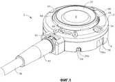
Фиг. 1 - вид в перспективе инъекционного порта с соединительным механизмом, конструктивно выполненным в соответствии с настоящим изобретением.FIG. 1 is a perspective view of an injection port with a connecting mechanism structurally constructed in accordance with the present invention.
Фиг. 2 - вид сверху инъекционного порта, показанного на фиг. 1.FIG. 2 is a top view of the injection port shown in FIG. one.
Фиг. 3 - вид снизу инъекционного порта, показанного на фиг. 1.FIG. 3 is a bottom view of the injection port shown in FIG. one.
Фиг. 4 - вид инъекционного порта, показанного на фиг. 1, в разрезе по линии 4-4 на фиг. 3.FIG. 4 is a view of the injection port shown in FIG. 1, in section along line 4-4 in FIG. 3.
Фиг. 5 - вид в перспективе с пространственным разделением деталей инъекционного порта, показанного на фиг. 1.FIG. 5 is an exploded perspective view of the injection port shown in FIG. one.
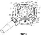
Фиг. 6 - вид в перспективе дна инъекционного порта, показанного на фиг. 1, изображающий соединительный механизм в отведенном положении.FIG. 6 is a perspective view of the bottom of the injection port shown in FIG. 1 depicting a connecting mechanism in a retracted position.
Фиг. 7 - вид в перспективе дна инъекционного порта, показанного на фиг. 1, аналогичный фиг. 6 и изображающий соединительный механизм в выдвинутом/сработавшем положении.FIG. 7 is a perspective view of the bottom of the injection port shown in FIG. 1, similar to FIG. 6 and depicting a connecting mechanism in the extended / actuated position.
Фиг. 8 - вид сбоку с местным разрезом, изображающий крепежный элемент соединительного механизма в отведенном положении.FIG. 8 is a side cross-sectional view showing a fastener of a connecting mechanism in a retracted position.
Фиг. 9 - вид сбоку с местным разрезом, аналогичный фиг. 8, изображающий крепежный элемент соединительного механизма, который перемещается приводной обоймой в выдвинутое/сработавшее положение.FIG. 9 is a side cross-sectional view similar to FIG. 8 depicting a fastener of a coupling mechanism that moves the drive cage to an extended / engaged position.
Фиг. 10 - вид сбоку с местным разрезом, аналогичный фиг. 8, изображающий крепежный элемент соединительного механизма в выдвинутом/сработавшем положении.FIG. 10 is a side cross-sectional view similar to FIG. 8 depicting a fastener of a connecting mechanism in an extended / actuated position.
Фиг. 11 - вид сбоку с местным разрезом, аналогичный фиг. 8, изображающий крепежный элемент соединительного механизма, который перемещается приводной обоймой в отведенное положение.FIG. 11 is a side cross-sectional view similar to FIG. 8, depicting a fastener of a connecting mechanism that moves the drive clip to a retracted position.
Фиг. 12 - вид сверху инъекционного порта, показанного на фиг. 1, с приводной обоймой, исключенной для иллюстрации положений шарнирных звеньев, когда крепежные элементы находятся в отведенном положении.FIG. 12 is a top view of the injection port shown in FIG. 1, with a drive clip excluded to illustrate the positions of the articulated links when the fasteners are in the retracted position.
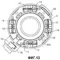
Фиг. 13 - вид сверху инъекционного порта, показанного на фиг. 1, с приводной обоймой, исключенной для иллюстрации положений шарнирных звеньев, когда крепежные элементы находятся в выдвинутом/сработавшем положении.FIG. 13 is a top view of the injection port shown in FIG. 1, with a drive clip excluded to illustrate the positions of the hinge links when the fasteners are in the extended / engaged position.
Фиг. 14 - увеличенный местный вид сверху визуального указателя положения и системы фиксации приводной обоймы соединительного механизма, показанного на фиг. 1, в отведенном положении.FIG. 14 is an enlarged local top view of the visual position indicator and the locking system of the drive sleeve of the connecting mechanism shown in FIG. 1, in the retracted position.
Фиг. 15 - увеличенный местный вид сверху визуального указателя положения и системы фиксации приводной обоймы соединительного механизма, показанного на фиг. 1, в выдвинутом/сработавшем положении.FIG. 15 is an enlarged local top view of the visual position indicator and the locking system of the drive clip of the connecting mechanism shown in FIG. 1, in the extended / actuated position.
Фиг. 16 - увеличенный местный вид в перспективе с пространственным разделением деталей штуцера и соединителя с фиксацией для инъекционного порта, показанного на фиг. 1.FIG. 16 is an enlarged perspective view with a spatial separation of the parts of the fitting and the connector with a fixation for the injection port shown in FIG. one.
Фиг. 17 - увеличенный местный вид в частичном разрезе соединителя с фиксацией, смонтированного на штуцере крепежного кольца диафрагмы, но не зафиксированного на месте установки.FIG. 17 is an enlarged partial view in partial section of a locking connector mounted on a fitting of a diaphragm fixing ring, but not fixed at the installation site.
Фиг. 18 - увеличенный местный вид в частичном разрезе, аналогичный фиг. 17, изображающий соединитель с фиксацией, зафиксированный на месте установки.FIG. 18 is an enlarged partial partial sectional view similar to FIG. 17 depicting a latching connector locked in place.
Фиг. 19 - увеличенный вид в перспективе защитной крышки.FIG. 19 is an enlarged perspective view of a protective cover.
Фиг. 20 - вид в перспективе установочного приспособления, разработанного для имплантации инъекционного порта, показанного на фиг. 1.FIG. 20 is a perspective view of a fixture designed for implanting the injection port shown in FIG. one.
Фиг. 21 - вид в перспективе с пространственным разделением деталей установочного приспособления, показанного на фиг. 20.FIG. 21 is an exploded perspective view of the installation tool shown in FIG. twenty.
Фиг. 22 - вид сбоку установочного приспособления, показанного на фиг. 20, с одной из двух половин корпуса и с изображением внутренних компонентов в неиспользованном, незадействованном положении.FIG. 22 is a side view of the adjusting device shown in FIG. 20, with one of the two halves of the housing and depicting internal components in an unused, unused position.
Фиг. 23 - вид сбоку установочного приспособления, показанного на фиг. 20, аналогичный фиг. 22, изображающий внутренние компоненты в использованном, задействованном положении.FIG. 23 is a side view of the adjusting device shown in FIG. 20, similar to FIG. 22 depicting internal components in a used, engaged position.
Фиг. 24 - увеличенный местный вид сбоку кулачкового механизма преобразования линейного движения в поворотное движение в установочном приспособлении, показанном на фиг. 20.FIG. 24 is an enlarged side elevational view of a cam mechanism for converting linear motion into rotary motion in the locating device shown in FIG. twenty.
Фиг. 25 - увеличенный вид сверху в перспективе установочного элемента установочного приспособления, показанного на фиг. 20.FIG. 25 is an enlarged top perspective view of a mounting member of the mounting fixture shown in FIG. twenty.
Фиг. 26 - увеличенный вид снизу в перспективе установочного элемента и приводного элемента порта установочного приспособления, показанного на фиг. 20.FIG. 26 is an enlarged bottom perspective view of the mounting member and the drive member of the port of the mounting fixture shown in FIG. twenty.
Фиг. 27 - вид с торца с местным вырезом установочного элемента установочного приспособления, показанного на фиг. 20.FIG. 27 is an end view with a local cutaway of a mounting element of the mounting fixture shown in FIG. twenty.
Фиг. 28 - увеличенный вид в разрезе инъекционного порта, показанного на фиг. 1, зафиксированного установочным элементом установочного приспособления, показанного на фиг. 20.FIG. 28 is an enlarged sectional view of the injection port shown in FIG. 1 fixed by the mounting element of the mounting device shown in FIG. twenty.
Фиг. 29 - увеличенный вид в разрезе инъекционного порта, показанного на фиг. 1, расположенного в установочном элементе установочного приспособления, показанного на фиг. 20, после того, как установочное приспособление приведено в действие для поворота приводного элемента установочного приспособления в развернутое положение.FIG. 29 is an enlarged sectional view of the injection port shown in FIG. 1 located in the mounting element of the mounting device shown in FIG. 20, after the mounting device is actuated to rotate the drive element of the mounting device to the deployed position.
Ниже даются подробные ссылки на настоящий предпочтительный вариант осуществления изобретения, пример которого представлен на прилагаемых чертежах.Detailed references are made below to the present preferred embodiment of the invention, an example of which is presented in the accompanying drawings.
ПОДРОБНОЕ ОПИСАНИЕDETAILED DESCRIPTION
В нижеследующем описании одинаковыми позициями обозначены одинаковые или соответствующие части на нескольких видах. Кроме того, необходимо понимать, что в нижеследующем описании такие термины, как передний, задний, внутренний, внешний и т.п. приведены для удобства, и их не следует истолковывать в ограничительном смысле. Терминология, используемая в настоящем патенте, не имеет ограничительного смысла, поскольку рассматриваемые в настоящем описании устройства или их участки можно прикреплять или использовать с другими ориентациями. Описание варианта осуществления изобретения приведено ниже с подробными ссылками на чертежи.In the following description, the same reference numbers indicate identical or corresponding parts in several views. In addition, it must be understood that in the following description, terms such as front, rear, inner, outer, etc. are for convenience only and should not be construed in a limiting sense. The terminology used in this patent does not have a restrictive meaning, since the devices or their portions described in the present description can be attached or used with other orientations. A description of an embodiment of the invention is provided below with detailed reference to the drawings.
На фиг. 1-5 представлено имплантируемое медицинское устройство, в частности, инъекционный порт, в целом, обозначенный позицией 2, который заключает в себе соединительный механизм, конструктивно выполненный в соответствии с настоящим изобретением. Хотя соединительный механизм на фигурах показан как объединенный с инъекционным портом 2, соединительный механизм можно использовать с любым другим имплантируемым медицинским устройством, для которого данный механизм подходит, включая, только для примера, водителей ритма, порты для сосудистого доступа, инъекционные порты (например, порты, применяемые с желудочными бандажами) и устройства стимулирования желудка.In FIG. 1-5 show an implantable medical device, in particular, an injection port, generally indicated by 2, which comprises a connecting mechanism, structurally made in accordance with the present invention. Although the connection mechanism in the figures is shown to be combined with
Инъекционный порт 2 содержит крепежное кольцо 4 диафрагмы, диафрагму 6 и корпус 8 порта. Инъекционный порт 2 с неразъемно выполненным соединительным механизмом содержит также, по меньшей мере, один крепежный элемент 10, приводную обойму 12 и множество шарнирных звеньев 14.
Как показано на фиг. 4, диафрагма 6, которая может быть выполнена из любого биосовместимого материала, например силикона, расположена частично внутри внутренней полости 16 крепежного кольца 4 диафрагмы с прилеганием к кольцевой полке 18. Крепежное кольцо 4 диафрагмы, корпус 8 порта и приводная обойма 12 могут быть выполнены из любого подходящего биосовместимого материала, обладающего достаточной жесткостью и прочностью, например простого полиэфироэфирокетона (сокращенно, PEEK). Крепежные элементы 10 и шарнирные элементы 14 могут быть выполнены из любого подходящего биосовместимого материала, например нержавеющей стали.As shown in FIG. 4, the
Корпус 8 порта содержит кольцевой обод 20, который охватывает верхнюю поверхность диафрагмы 6 по кольцевому участку. Корпус 8 порта фиксируется к крепежному кольцу 4 диафрагмы множеством пальцев 22, которые расположены в соответствующих отверстиях 24, выполненных в углублениях 24a в корпусе 8 порта, и которые продолжаются внутрь в соответствующие углубления 26, выполненные по нижней окружности крепежного кольца 4 диафрагмы. Пальцы 22 могут быть выполнены из любого подходящего биосовместимого материала, например, нержавеющей стали.The
Высота несжатой диафрагмы 6 составляет приблизительно 5 мм по внешнему диаметру, и несжатый диаметр составляет приблизительно 18 мм. Выступающий диаметр для доступа в резервуар 30 составляет приблизительно 14 мм. Расстояние между нижней поверхностью кольцевого обода 20 и кольцевой полкой 18 составляет приблизительно 4 мм, так что диафрагма 6 сжимается приблизительно на 20% для достаточного самовосстановления и, тем самым, обеспечения непроницаемости системы для текучей среды под давлением и, при этом, все еще обеспечивает низкий вертикальный профиль.The height of the
Пластина 28 расположена в выточке 16a, выполненной в дне крепежного кольца 4 диафрагмы, под диафрагмой 6 и камерой или резервуаром 30 для текучей среды. Как показано на фиг. 4, пластина 28 не контактирует с боковой стенкой 16b. В показанном варианте осуществления, пластина 28 является металлической, например из нержавеющей стали. Когда иглу вводят через диафрагму 6 для введения или отбора текучей среды из камеры 30 для текучей среды, например, с целью регулирования размера регулируемого желудочного бандажа, металлическая пластина 28 будет защищать крепежное кольцо 4 диафрагмы от прокола и обеспечивать тактильную обратную связь хирургу через иглу, чтобы указывать, когда игла достигает дна резервуара 30. Пластина 28 может быть прикреплена к крепежному кольцу 4 диафрагмы любым подходящим способом. В показанном варианте осуществления, пластина 28 зафиксирована в заданном месте фиксирующим выступом 4a, продолжающимся над окружным краем пластины 28, что лучше всего показано на фиг. 4, 28 и 29. Сначала фиксирующий выступ 4a выступает вверх как кольцевой выступ, обеспечивающий просвет для вставки пластины 28 в выточку в нижней части крепежного кольца 4 диафрагмы, и затем фиксирующий выступ 4a закатывают или иным способом деформируют для перекрывания, по меньшей мере, участка по окружности пластины 28 и, тем самым, фиксации пластины 28. В показанном варианте осуществления диаметр выточки 16a меньше, чем диаметр боковой стенки 16b, что обеспечивает пространство для формирования кольцевого выступа и для его деформирования с образованием фиксирующего выступа 4a. Пластину 28 можно вставить при формовании, при этом, фиксирующий выступ 4a является формованным, как показано.The
Крепежное кольцо 4 диафрагмы содержит проходное отверстие 32, которое пневмогидравлически сообщается с камерой 30 для текучей среды, и которое образовано штуцером 34, продолжающимся от наружной окружности в смежном положении с дном крепежного кольца 4. Трубка 36, которая в показанном варианте осуществления ведет в регулируемый желудочный бандаж (не показанный), присоединена к штуцеру 34 и поджата сдавливанием к кольцевому буртику 38 соединителем 40, который расположен вокруг трубки 36 и прикреплен к корпусу 8 порта, как описано ниже. Гильза 42 расположена вокруг трубки 36 и прикреплена к соединителю 40 кольцевыми буртиками 44. Гильза 42 ослабляет натяжение трубки 36 и, тем самым, предотвращает образование перегибов трубки 36 при боковой нагрузке.The
Приводная обойма 12 прикреплена к корпусу 8 порта. Хотя в показанном варианте осуществления приводная обойма 12 изображена в виде кольцевой обоймы, закрепленной с возможностью вращения в корпусе 8 порта, приводная обойма 12 может быть любой подходящей конфигурации и закреплена любым подходящим способом, позволяющим приводной обойме 12 функционировать так, чтобы перемещать крепежные элементы 10 между развернутым и неразвернутым положениями, включительно. Как показано на фиг. 5, корпус 8 порта содержит множество продолжающихся вниз и наружу лапок 46. В показанном варианте осуществления имеется четыре равноотстоящих лапки 46. Приводная обойма 12 содержит равное количество соответствующих углублений 48, каждое с дуговидным низом 50. Для установки приводной обоймы 12 на корпусе 8 порта совмещают углубления 48 с лапками 46 и нажимают вниз, при этом, лапки 46 временно отклоняются внутрь до тех пор, пока лапки 46 не достигают выемок 48 и не отодвигаются наружу с расположением нижних кромок 46a в углублениях 48, чтобы тем самым зафиксировать приводную обойму. Длины лапок 46 и глубина углублений 48 допускают некоторый люфт в осевом направлении между приводной обоймой 12 и корпусом 8 порта, как поясняется ниже.The
Приводная обойма 12 может поворачиваться, в целом, вокруг центральной оси корпуса 8 порта. В показанном варианте осуществления приводная обойма 12 может поворачиваться на угол около 40 градусов, однако можно применить любой подходящий угол. В показанном варианте осуществления, когда приводная обойма 12 повернута в направлении развертывания с обусловленным тем самым перемещением крепежных элементов 10 в развернутое положение, поворот приводной обоймы 12 за полностью развернутое положение ограничен краем 48c, контактирующим с лапкой 46.The
Система фиксации образована парой пространственно разнесенных приподнятых фиксирующих ребер 48a, 48b, выступающих внутрь из стенки каждого углубления 48, и соответствующим приподнятым выступом 46b, выступающим наружу из лапки 46. Система фиксации помогает предотвращать поворот приводной обоймы 12 и выход крепежных элементов 10 из полностью отведенного или полностью выдвинутого сработавшего состояний под действием вибрации или случайной нагрузки, как поясняется ниже.The locking system is formed by a pair of spatially spaced apart raised locking
Приводная обойма 12 содержит множество пространственно разнесенных отверстий или пазов 54, которые можно зацеплять любым подходящим приспособлением для передачи необходимого крутящего момента на приводную обойму 12 для выдвижения крепежных элементов 10 в задействованное положение. Пазы 54 выполнены с возможностью зацепления существующими на рынке приспособлениями, прямоугольными в показанном варианте осуществления, или нижеописанным специальным установочным приспособлением. Корпус 6 порта содержит множество углублений 56, которые расположены вокруг его нижней наружной окружности и которые выполнены с возможностью взаимодействия со специальным установочным приспособлением нижеописанным образом.The
Как показано также на фиг. 6 и 7, крепежное кольцо 4 диафрагмы содержит множество установочных лапок 58, выступающих наружу из положений около нижней наружной окружности крепежного кольца 4 диафрагмы. Установочная лапка 58a может быть выполнена в одно целое со штуцером 34. Лапки 58 и 58a расположены в соответствующих, сопряженных по форме, углублениях 60, выполненных во внутренней поверхности корпуса 8 порта для правильного совмещения крепежного кольца 4 диафрагмы с корпусом 8 порта.As also shown in FIG. 6 and 7, the
На фиг. 6 показаны крепежные элементы 10 в отведенном положении. Как можно видеть, крепежные элементы 10 расположены в соответствующих углублениях или пазах 60, выполненных в корпусе 8 порта. На фиг. 7 крепежные элементы 10 показаны в выдвинутом или сработавшем положении, продолжающимися из пазов 60. Поворот приводной обоймы 12 перемещает крепежные элементы 10 из отведенного положения в выдвинутое положение.In FIG. 6 shows the
Фиг. 8-11 представляют собой ряд фигур, иллюстрирующих работу приводной обоймы 12 и одного из множества крепежных элементов 10, причем очевидно, что работа одного из крепежных элементов 10 может быть идентичной для всех крепежных элементов 10, которые в одном варианте осуществления могут перемещаться из развернутого положения в неразвернутое положение одновременно. На фиг. 8 изображен крепежный элемент 10 в полностью отведенном состоянии, неразвернутом положении, находящийся полностью внутри паза 62, так что острие 64 не выставлено наружу. Это предотвращает случайный укол хирурга или протыкание любого другого объекта острием 64. Как показано, приводная обойма 12 повернута против часовой стрелки, насколько допускают углубления 48 и лапки 46. В данном положении выступы 46b расположены по часовой стрелке от ребер 48b, как показано на фиг. 14. Первые концы 14a шарнирных элементов 14 установлены с возможностью поворота в приводной обойме 12, с пространственным разнесением, в положениях, соответствующих положениям крепежных элементов 10. Вторые концы 14b расположены в прорезях 66 крепежных элементов 10.FIG. 8-11 are a series of figures illustrating the operation of the
Чтобы привести в действие соединительный механизм, неразъемную приводную обойму 12 поворачивают в направлении развертывания, которое в одном варианте осуществления показано как направление по часовой стрелке (причем, можно применить любое подходящее направление, конструктивно обеспечивающее приведение соединительного механизма в действие), и выступ 46b проходит ребро 48b с возможным изданием звукового сигнала дополнительно к тактильному сигналу для хирурга. Второй конец 14b шарнирного элемента 14 освобождается для перемещения внутри прорези 66 во время приведения в действие по мере того, как усилие, которое поворачивает крепежный элемент 10 в выдвинутое положение, передается на крепежный элемент 10 посредством взаимодействия между кулачковой поверхностью 68 крепежного элемента 10 и приводной кулачковой поверхностью 70 приводной обоймы 12. По мере того, как приводная обойма 12 поворачивается по часовой стрелке, приводная кулачковая поверхность 70 зацепляет и толкает кулачковую поверхность 68 с поворотом крепежного элемента 10 вокруг шарнирного пальца 22. Большая часть усилия со стороны приводной кулачковой поверхности 70 действует тангенциально на кулачковую поверхность 68 со сдвигом от центра относительно шарнирного пальца 22 и, тем самым, вынуждает крепежный элемент 10 поворачиваться. Во время приведения в действие конец 14b шарнирного элемента 14 остается свободным для перемещения внутри прорези 66 и не прилагает приводного усилия для поворота крепежного элемента 10.To actuate the coupling mechanism, the
Как показано на фиг. 9, крепежный элемент 10 поворачивается приблизительно на половину пути в пределах его диапазона поворота, приблизительно, на 90 градусов, в результате поворота приводной обоймы 12 по часовой стрелке. По мере того, как приводная обойма 12 поворачивается по часовой стрелке, усилие между кулачковой поверхностью 70 приводной обоймы и кулачковой поверхностью 68 вынуждает приводную обойму 12 перемещаться немного вверх, насколько позволяют назначенные допуска размеров компонентов. По мере того, как приводная обойма 12 поворачивается дополнительно по часовой стрелке из положения, показанного на фиг. 9, кулачковая поверхность 70 приводной обоймы продолжает зацеплять и толкать кулачковую поверхность 68 с поворотом крепежного элемента 10 дальше против часовой стрелки.As shown in FIG. 9, the
На фиг. 10 приводная обойма 12 повернута по часовой стрелке на полный ход, при этом выступ 46b заведен нажимом за фиксирующее ребро 48a (см. фиг. 15). В данном положении крепежный элемент 10 повернут на его полный ход, почти на 180 градусов в показанном варианте осуществления, при этом острие 64 расположено в пазу 62. В данном положении, кулачковая поверхность 70 приводной обоймы находится за центром, и приводная обойма 12 сопротивляется отводящему назад усилию свертывания, прилагаемому к крепежному элементу 10, когда кулачковая поверхность 68 действует на кулачковую поверхность 70 приводной обоймы в направлении, для которого характерно выталкивание приводной обоймы 12 вверх вместо вращения приводной обоймы 12. Дистальный концевой участок крепежного элемента 10 выполнен, по существу, в виде балансира, изображенного, в основном, с прямоугольным сечением по длине и с сужением к острию 64. Когда крепежный элемент 10 продолжается приблизительно на 180 градусов в полностью выдвинутом, развернутом положении, усилия, которые могут воздействовать на крепежные элементы 10, имеют тенденцию к действию через ось поворота, образованную шарнирным пальцем 22, вместо вращения крепежных элементов 10. Целесообразно отметить, что хотя палец 22 показан в виде детали, отдельной от крепежного элемента 10, две данные детали могут быть неразъемной или даже единой конструкцией.In FIG. 10, the
Если желательно отвести крепежные элементы 10, например, для извлечения или переустановки имплантированного устройства, приводную обойму 12 можно повернуть в направлении свертывания, против часовой стрелки в одном показанном варианте осуществления. Из положения приводной обоймы 12, показанного на фиг. 10, приводную обойму 12 можно повернуть против часовой стрелки, при этом кулачковая поверхность 70 приводной обоймы скользит по кулачковой поверхности 68 и не поворачивает крепежный элемент 10. В показанном варианте осуществления продолжение вращения приводной обоймы 12 против часовой стрелки выводит кулачковую поверхность 70 из контакта с кулачковой поверхностью 68 без оказания существенного поворотного усилия на крепежный элемент 10 до тех пор, пока второй конец 14b шарнирного элемента не достигает такого места в прорези 66, например, с одной стороны прорези 66, где шарнирный элемент 14 начинает подтягивать за прорезь 66, что вынуждает крепежный элемент 10 поворачиваться и начинать отведение.If it is desired to remove the
На фиг. 11 приводная обойма 12 показана перемещенной против часовой стрелки по сравнению с положением, показанным на фиг. 10, и крепежный элемент 10 повернут, приблизительно, на половину пути в пределах его хода. Как можно видеть из сравнения фиг. 9 с фиг. 11, приводная обойма 12 находится в разных положениях при пребывании крепежного элемента 10 в одном положении, в зависимости от того, задействован или нет (отведен) соединительный механизм. Указанное является следствием свободного хода, который имеет место, когда шарнирный элемент 14 подтягивает прорезь 66, в сравнении с ситуацией, когда кулачковая поверхность 70 приводной обоймы нажимает непосредственно на кулачковую поверхность 68. Для полного отведения крепежных элементов 10 приводную обойму 12 поворачивают до тех пор, пока фиксирующий выступ 46b не проскочит фиксирующее ребро 48b.In FIG. 11, the
Как показано на фиг. 8, когда крепежные элементы 10 приходят в полностью свернутое положение, острие 64 может расположиться полностью в пазу или углублении 62. Дальнейший поворот приводного элемента 12 в сторону свертывания не допускается шарнирным элементом 14, дальнейшее перемещение которого не допускается крепежным элементом 10.As shown in FIG. 8, when the
Как показано на фиг. 2 и 3, приводная обойма 12 содержит отверстия 52a, выполненные в ней насквозь, которые совмещаются с соответствующими отверстиями 52b, выполненными в корпусе 8 порта, когда приводная обойма находится в неразвернутом положении. Отверстия 52a и 52b могут быть использованы хирургом для пришивания инъекционного порта 2, если не применяют неразъемный соединительный механизм.As shown in FIG. 2 and 3, the
На фиг. 12 и 13 соединительный механизм показан без приводной обоймы 12. Шарнирные элементы 14 показаны в их фактических положениях, когда первые концы 14a установлены в приводную обойму 12, в развернутом и неразвернутом состояниях.In FIG. 12 and 13, the connecting mechanism is shown without the
На фиг. 14 и 15 представлен вид сверху на визуальный указатель положения и участок системы фиксации приводной обоймы соединительного механизма, встроенного в инъекционный порт 2. На фиг. 14 соединительный механизм показан в отведенном, свернутом состоянии или положении. В данном положении фиксирующий выступ 46b находится в положении по часовой стрелке от фиксирующего ребра 48b и, следовательно, в свернутом положении фиксации. На фиг. 15 соединительный механизм показан в задействованном или развернутом положении. В данном положении фиксирующий выступ 46b находится в положении против часовой стрелки от фиксирующего ребра 48b и, следовательно, в развернутом положении фиксации.In FIG. 14 and 15 show a top view of the visual position indicator and a portion of the locking system of the drive cage of the connecting mechanism integrated in the
На фиг. 14 и 15 показан визуальный индикатор состояния соединительного механизма. Как показано на фиг. 14, можно применять знаки, например иконку 72 незапертого замка и иконку 74 запертого замка, сформованные как одно целое с приводной обоймой 12. Допустимо применение любого подходящего графического индикатора, причем данный индикатор может быть напечатан или нанесен иным подходящим образом. Корпус 6 порта может содержать индикатор 76 в качестве ориентира для подвижных знаков. Можно предусмотреть стрелку 78 для указания на двунаправленный характер движения приводного элемента 12.In FIG. 14 and 15 show a visual indicator of the status of the connecting mechanism. As shown in FIG. 14, signs can be used, for example, the
На фиг. 16-18 показано соединение с фиксацией между соединителем 40 и корпусом 6 порта. На фиг. 16 представлен вид в перспективе с пространственным разделением деталей, показывающий штуцер 34, частично окруженный выступом 78. На фиг. 17 выступ 78 изображен в сечении, с соединителем 40, в общем, расположенным вокруг штуцера 34 и трубки 36, расположенными соосно в круговой выточке 78c выступа 78. Соединитель 40 содержит пару выступов 40a, 40b, продолжающихся наружу из данного соединителя. При сборке соединитель 40 направляют вдоль трубки 36 и штуцера 34, при этом выступы 40a и 40b совмещают с отверстиями 78a и 78b в выступе 78. В положении с выступами 40a и 40b, совмещенными с круговой выточкой 78c, соединитель 40 поворачивают для его фиксации в заданном месте. Во время поворота, фиксирующая кромка 78d создает помеху, препятствующую повороту выступа 40a, но имеет такой размер, чтобы выступ 40a мог провернуться мимо, в положение фиксации, показанное на фиг. 18.In FIG. 16-18 show a latch connection between
На фиг. 19 показана защитная крышка 80, которую можно прикреплять с возможностью разъема к дну инъекционного порта 2 для закрывания крепежных элементов 10, чтобы защитить пользователей от случайного контакта с остриями 64 во время обращения с инъекционным портом 2. Защитная крышка 80 содержит корпус 82 с кольцевым ободом 84 и поднятым центром 86, образующими кольцевое углубление 88. Защитную крышку 80 можно ориентировать и фиксировать на инъекционном порте посредством любой подходящей конфигурации. Как показано, корпус 82 содержит множество дуговидных фиксирующих лапок 90, продолжающихся вверх из поднятого центра 86. Дуговидные фиксирующие лапки 90 являются сопряженными по форме с соответствующими дуговидными пазами 92, лучше всего показанными на фиг. 3, 6 и 7, и могут быть снабжены показанными ребрами. Защитную крышку 80 закрепляют к инъекционному порту 2 вставкой дуговидных фиксирующих лапок 90 в дуговидные пазы 92, которые имеют размеры для фиксации лапок 90. Таким образом, крепежные элементы 10 совмещаются с кольцевым углублением 88, размер которого позволяет крепежным элементам 10 выступать без контакта с защитной крышкой 80. Как показано, поскольку дуговидные фиксирующие лапки 90 и дуговидные пазы 92 имеют, соответственно, одинаковые размеры и расположены с равными интервалами, защитная крышка 80 не имеет какого-то определенного положения и может быть прикреплена к инъекционному порту 2 в четырех разных положениях. Защитная крышка 80 содержит ушко 94 для открывания с множеством выступающих ребер 96 для создания более удобно захватываемой поверхности. Хотя ушко 94 для открывания можно ориентировать в любом подходящем направлении, в представленном варианте осуществления положение ушка 94 для открывания относительно дуговидных фиксирующих лапок 90 обеспечивает расположение ушка для открывания под углом 45 градусов к направлению соединителя 40. Лапки 90 и пазы 92 могут быть любой подходящей формы.In FIG. 19 shows a
Как упоминалось выше, соединительный механизм может быть приведен в действие зацеплением пазов 54 имеющимися на рынке приспособлениями или специальным установочным приспособлением. На фиг. 20 показано установочное приспособление, обозначенное, в целом, позицией 100, которое выполнено с возможностью позиционирования, приведения в действие, выведения из действия, извлечения или переустановки инъекционного порта 2. Следует отметить, что практическое применение аспектов настоящего изобретения в виде установочного приспособления не ограничено конкретным вариантом осуществления установочного приспособления, представленным в настоящем описании.As mentioned above, the connecting mechanism can be actuated by engaging the
Как показано на фиг. 20, установочное приспособление 100 содержит корпус 102, установочный элемент 104, приводную рукоятку 106 и предохранительный переключатель 108. Как описано ниже, инъекционный порт 2 может быть установлен в установочный элемент 104, с расположением выступа 78 и бобышки 96 в установочных вырезах 110 и 112. Установочный элемент 104 расположен под углом относительно корпуса 102, что упрощает и облегчает наблюдение инъекционного порта 2 во время имплантации. В показанном варианте осуществления угол составляет 20 градусов, и участок стержня корпуса 102 равен 10 см.As shown in FIG. 20, the mounting
Как показано на фиг. 21, корпус 102 содержит первую и вторую половины 102a и 102b, собираемые друг с другом для заключения в них внутренних компонентов. За исключением установочных штифтов 202, шарнирных пальцев 114 и пальцев, половины 102a и 102b корпуса, по существу, аналогичны друг другу. Установочные штифты 202, показанные выступающими из половины 102a корпуса, входят в соответствующие, сопряженные по форме отверстия (не показанные) в половине 102b корпуса. Ввод множества установочных штифтов 202 в отверстия достаточен для скрепления половин 102a и 102b корпуса воедино. В качестве альтернативы, штифты 202 могут выступать из половины 102b корпуса, а отверстия могут быть выполнены в половине 102a корпуса. Можно применить любую подходящую конфигурацию для сборки и скрепления половин 102a и 102b корпуса воедино.As shown in FIG. 21, the
Приводная рукоятка 106 содержит первую и вторую половины 106a и 106b. Установочные штифты 204, показанные выступающими из половины 106a приводной рукоятки, входят в соответствующие, сопряженные по форме, отверстия (не показанные) в половине 106b приводной рукоятки. В качестве альтернативы, штифты 204 могут выступать из половины 106b приводной рукоятки, а отверстия могут быть выполнены в половине 106a приводной рукоятки. Можно применить любую подходящую конфигурацию для сборки и скрепления половин 106a и 106b приводной рукоятки воедино. Половина 102b корпуса содержит шарнирный палец 114b, который служит поворотной опорой для приводной рукоятки 106 на одном конце и продолжается через шарнирные отверстия 116a и 116b в отверстие 114a. Половина 102a корпуса содержит шарнирный палец 118b (см. фиг. 22), который служит поворотной опорой для предохранительного переключателя 108. Половины 102a и 102b корпуса, установочный элемент 104, половины 106a и 106b приводной рукоятки и предохранительный переключатель 108 могут быть выполнены из любого биосовместимого материала, например, поликарбоната.The
Как показано на фиг. 21-24, установочное приспособление 100 содержит кулачок 120, приводной стержень 122 с гибким стержнем 124, штифт 126 приводного стержня, возвратную пружину 128 кулачка, предохранительную поджимную пружину 130 и приводной элемент 132. Приводной элемент 132 выполнен с возможностью осуществления развертывания или свертывания соединительного механизма медицинского имплантата. Кулачок 120 содержит шток 134 и кулачковую втулку 136. Верхний конец штока 134 имеет «T-образную» конфигурацию, закачивающуюся поперечным элементом 138. Кулачковая втулка 136 образует полую внутреннюю часть и пару пространственно разнесенных, сопряженных по форме, кулачковых дорожек 140a и 140b, выполненных на противоположных сторонах кулачковой втулки 136. Верхний конец 122a приводного стержня 122 расположен частично внутри полой внутренней части, образованной кулачковой втулкой 136, с захватом в данной втулке штифтом 126 приводного стержня. Штифт 126 приводного стержня имеет такие размеры, что каждый конец расположен внутри соответствующей кулачковой дорожки 140a, 140b. Длина полой внутренней части позволяет верхнему концу 122a выполнять в ней возвратно-поступательное движение, при этом кулачковые дорожки 140a и 140b придают вращение приводному стержню 122 посредством штифта 126 приводного стержня во время возвратно-поступательного движения. Кулачок 120, приводной стержень 122 и приводной элемент 132 могут быть выполнены из любого подходящего материала, обладающего достаточной жесткостью и прочностью. В показанном варианте осуществления кулачок 120 и приводной элемент 132 выполнены из жидкокристаллического полимера, например Vectra™ LCP, и приводной стержень 122 выполнен из полимера PPE+PS, например Noryl™. Штифт 126 приводного стержня и возвратная пружина 128 кулачка могут быть выполнены из любого подходящего материала, например нержавеющей стали.As shown in FIG. 21-24, the mounting
Кулачок 120 удерживается между частями 102a и 102b корпуса, и, в одном варианте осуществления, например в показанном варианте, может совершать возвратно-поступательное движение. Кулачковая втулка 136 содержит пространственно разнесенные, в целом, плоские внешние поверхности 142a и 142b, сквозь которые выполнены кулачковые дорожки 140a и 140b. Поверхности данных дорожек 140a и 140b расположены между направляющими стенками 144a и 144b, выполненными в частях 102a и 102b корпуса. Кулачковая втулка 136 содержит также противоположно направленные выемки 146a и 146b (см. фиг. 23), которые направляются для возвратно-поступательного движения вдоль оси направляющими 148a и 148b (не показанными), выполненными, соответственно, в частях 102a и 102b корпуса. Верхний конец штока 134 и поперечный элемент 138 расположены посередине между половинами 106a и 106b приводной рукоятки. Каждая половина 106a, 106b приводной рукоятки содержит кулачковую дорожку 150, образованную парой пространственно разнесенных стенок 150a и 150b, выступающих из внутренних поверхностей половин 106a и 106b приводной рукоятки. Кулачковая дорожка 150 выполнена с возможностью вмещения и направления поперечного элемента 138 по мере того, как приводную рукоятку 106 поворачивают вокруг пальца 114, и, тем самым, принуждают кулачок 120 к сдвиганию линейно вниз в корпус 102.A
Приводной стержень 122 содержит кольцо 152, которое вмещается в пазы 154a и 154b (не показанные), выполненные в половинах, соответственно, 102a и 102b корпуса. Пазы 154a и 154b служат допускающей поворот опорой для приводного стержня 122. Приводной стержень 122 и кулачок 120, в общем, соосны и расположены на одной прямой один с другим с образованием, тем самым, оси стержневого участка корпуса 102. Когда кулачок 120 двигается вниз, штифт 126 приводного стержня движется по кулачковым дорожкам 140a и 140b и, при этом, вынуждает приводной стержень 122 поворачиваться, поэтому линейное движение преобразуется в поворотное движение. Возвратная пружина 128 кулачка обеспечивает расчетное возвратное усилие на кулачковую втулку 136.The
Гибкий стержень 124 опирается на множество ребер 156, выполненных в каждой половине корпуса 102a, 102b, которые поддерживают изгиб гибкого стержня 124, который позволяет передавать вращательное движение на приводной элемент 132, который расположен под углом к стержню корпуса 102. Гибкий стержень 124 может быть выполнен из любого подходящего биосовместимого материала, например нержавеющей стали. В показанном варианте осуществления гибкий стержень 124 имеет многожильную конструкцию, с центральной жилой, содержащей несколько слоев проволоки, намотанной вокруг данной жилы. Концы 124a и 124b гибкого стержня 124 могут быть прикреплены к концу 122b и приводному элементу 132, соответственно, любым подходящим способом, который достаточно ограничивает угловой зазор конца для предотвращения или сведения к минимуму свободного поворотного хода. В показанном варианте осуществления конец 124a был заформован в конец 122b, и конец 124b был запрессован в приводной элемент 132. В качестве альтернативы, конец 124a может быть запрессован в конец 122b, и конец 124b заформован в приводной элемент 132, или тот и другой могут быть запрессованы, или тот и другой могут быть заформованы (с соответствующим изменением конфигурации установочного элемента 104 для обеспечения возможности сборки).The
Как показано на фиг. 21-25, приводной элемент 132 содержит дисковидный элемент 158 и стержень 160, продолжающийся из него вверх. Верхний конец стержня 160 содержит пару выступающих вверх лапок 162a и 162b. Установочный элемент 104 содержит втулку 164, образующую проходящее сквозь него отверстие 166. Отверстие 166 выполнено по форме для вмещения и закрепления с возможностью поворота стержня 160 и содержит две продолжающиеся наружу дугообразные выемки 168a и 168b, предназначенные для обеспечения сборочного зазора для лапок 162a и 162b, допускающего вставку втулки 164 в отверстие 166. Длины стержня 160 и втулки 164 назначены так, чтобы лапки 162a и 162b располагались над верхней поверхностью 164a втулки 164 и, тем самым, допускали поворот приводного элемента 132, но удерживали его в аксиальном положении относительно втулки 164. Ограничители 170 и 170b выступают вверх из верхней поверхности 164a для ограничения поворота приводного элемента 132. Отверстие 166 определяет центральную ось установочного элемента 104, вокруг которой поворачивается приводной элемент 132. Центральная ось установочного элемента 104 расположена под углом к оси стержневого участка корпуса 102, как упоминалось ранее.As shown in FIG. 21-25, the
Втулка 164 содержит пару противоположно продолжающихся выступов 172a и 172b, которые фиксируют установочный элемент 104 порта к корпусу 102 и предотвращают поворот. Половины 102a и 102b корпуса содержат соответствующие углубления 174a (см. фиг. 21) и 174b (не показанное), по форме сопряженные с выступами 172a и 172b.The
Как показано также на фиг. 26 и 27, дисковидный элемент 158 приводного элемента 132 расположен внутри установочного элемента 104. Приводной элемент 132 содержит пару пространственно разнесенных выступов 176a и 176b, продолжающихся из прилегающей окружности 158a элемента 158. Выступы 176a и 176b являются сопряженными по форме с отверстиями 54. В показанном варианте осуществления, дистальные концы выступов 176a и 176b сужаются для большего удобства ввода выступов 176a и 176b в отверстия 54. Для создания разъемного контакта между приводным элементом 132 и приводной обоймой 12 можно применить любую подходящую конфигурацию, допускающую приведение в движение приводной обоймы 12.As also shown in FIG. 26 and 27, the
Дисковидный элемент 158 содержит также пару пространственно разнесенных кулачков 178a и 178b, которые продолжаются наружу и вверх от окружного края 158a элемента 158. На фиг. 27 кулачок 178a показан в разрезе, взятом вблизи нижней поверхности элемента 158. Кулачки 178a и 178b содержат уклоны 180a и 180b, которые начинаются с окружного края 158a и выводят к поверхностям 182a и 182b, соответственно. Каждая поверхность 182a, 182b является дуговидной, в показанном варианте осуществления изображенной, в основном, с постоянным радиусом.The disk-shaped
В показанном варианте осуществления установочный элемент 104 содержит пару пространственно разнесенных кронштейнов 184a и 184b, каждый с ребром 186a и 186b, соответственно. Для ясности, на фиг. 27 кронштейн 184a изображен в сечении, через ребро 186a на том же уровне, как и в случае с кулачком 178a. На дистальных концах данных кронштейнов 184a и 184b содержатся соответствующие продолжающиеся внутрь фланцы 188a и 188b. Фланцы 188a и 188b являются сопряженными по форме с углублениями 56 на корпусе 6 порта и выполнены с возможностью зацепления уступов 56a, когда инъекционный порт 2 удерживается установочным элементом 104.In the shown embodiment, the mounting
В показанном варианте осуществления, в незадействованном состоянии, выступы 176a и 176b, в основном, совмещены с кронштейнами 184a и 184b, соответственно, хотя выступы 176a и 176b могут находиться в любом положении, которое соответствует положению приводного конструктивного элемента приводной обоймы 12, которым в показанном варианте осуществления являются отверстия 54. Когда нажимают на приводную рукоятку 106, приводной элемент 132 поворачивается (против часовой стрелки в показанном варианте осуществления, при наблюдении снизу) с перемещением кулачков 178a и 178b таким образом, что уклоны 180a и 180b контактируют с ребрами 186a и 186b, соответственно, и, тем самым, отклоняют кронштейны 184a и 184b наружу. Когда поверхности 182a и 182b зацепляют ребра 186a и 186b, кронштейны 184a и 184b отклоняются на расстояние, достаточное для перемещения фланцев 188a и 188b в положение, в котором они больше не продолжаются в углубления 56 или не контактируют с уступами 56a, что высвобождает инъекционный порт 2 из установочного элемента 104.In the shown embodiment, in the idle state, the
На фиг. 28 изображен инъекционный порт 2, расположенный в установочном элементе 104 и удерживаемый в нем, причем корпус выступа 78 и бобышка 96 расположены в вырезах 110 и 112, соответственно (см. фиг. 20, но не показано на фиг. 28). Как видно из фигуры, выступы 176a и 176b продолжаются в отверстия 54 приводной обоймы 12, и фланцы 188a и 188b продолжаются в углубления 56 с проксимально расположенными уступами 56a. Предохранительная крышка 80 присоединена к инъекционному порту 2, когда инъекционный порт 2 вставлен в установочный элемент 104 и закрывает крепежные элементы 10 (не показанные на фиг. 28).In FIG. 28 depicts an
Как показано также на фиг. 20 и 22, чтобы вставить инъекционный порт 2 в установочный элемент 104, приводную рукоятку 106 ориентируют в неразвернутое положение, чтобы приводной элемент 132 находился в неразвернутом положении. Приводную обойму 12 ориентируют в неразвернутое положение и вставляют в установочный элемент 104, при этом корпус выступа 78 и бобышка 96 располагаются в вырезах 110 и 112, соответственно.As also shown in FIG. 20 and 22, in order to insert the
Как видно на фиг. 20, приводная рукоятка 106 может содержать визуальный указатель, чтобы показывать, находится ли приводная рукоятка 106 полностью в неразвернутом состоянии, например иконку 190 незапертого замка, и указатель, чтобы показывать, находится ли приводная рукоятка 106 в развернутом состоянии, например иконку 192 запертого замка. Данную визуальную индикацию можно обеспечить любым подходящим способом, например формованием как одно целое с приводной рукояткой 106, наклеиванием адгезивной пленки или чего-то подобного или прямым печатанием на приводной рукоятке 106. С изображенным указателем иконка 190 незапертого замка видна вблизи верхней кромки корпуса 102, но можно применить и другие конфигурации для индикации, например окно или нечто подобное, выполненное в корпусе 102 для демонстрации обозначений.As seen in FIG. 20, the
Для применения установочный элемент 104 и участок 102, при необходимости, вводятся хирургом через рассечение и помещаются в заданном положении с прилеганием к ткани тела, к которой планируется прикрепить медицинский имплантат (которым в показанном варианте осуществления является инъекционный порт 2). Угол между установочным элементом 104 и корпусом 102 позволяет хирургу непосредственно наблюдать место. Когда инъекционный порт 2 находится в заданном положении, выдвигают, по меньшей мере, один крепежный элемент 10 из неразвернутого положения в развернутое положение по кольцевому пути для зацепления за ткань. Крепежные элементы 10 позволяют прикреплять инъекционный порт 2 к ткани с прочностью фиксации, равной или превышающей прочность при пришивании хирургическими нитями. Предохранительный переключатель 108 поворачивают вокруг шарнирного пальца 118 и, тем самым, извлекают фиксирующую лапку 194 из нижнего отверстия 196, что позволяет повернуть приводную рукоятку 106 вокруг шарнирного пальца 114. Данное действие вынуждает кулачковую дорожку 150 перемещать поперечный элемент 138 вниз и, тем самым, вынуждает кулачковую втулку 136 поворачивать приводной стержень 122 с соответствующим поворотом приводного элемента 132 относительно установочного элемента 104.For use, the
Поворот приводного элемента 132 приводит в действие приводную обойму 12 путем ее поворота. Зацепление выступа 78 и бобышки 96 за вырезы 110 и 112, соответственно, предотвращает поворот корпуса 8 порта, что обеспечивает перемещение приводной обоймы 12 относительно порта 8 корпуса.The rotation of the
После того, как приводная рукоятка 106 достигает развернутого положения, фиксирующая лапка 194 вжимается в верхнее отверстие 198 с фиксацией приводной рукоятки 106 в развернутом положении. В показанном варианте осуществления, пружина 130 поджимает фиксирующую лапку 194 с усилием, достаточным для издания звукового сигнала, когда фиксирующая лапка 194 входит с щелчком в верхнее отверстие 198, что обеспечивает звуковую сигнализацию о том, что приводная рукоятка 106 и, следовательно, приводная обойма 12 и крепежные элементы 10 развернуты полностью. Как показано на фиг. 29, когда приводная рукоятка 106 находится в развернутом положении, приводная обойма 12 уже повернута, и крепежные элементы 10 находятся в развернутом положении с прониканием в ткань тела, например, в прямую мышцу живота. Кулачки 178a и 178b повернуты в положение, в котором поверхности 182a и 182b прилегают к ребрам 186a и 186b, при этом, кронштейны 184a и 184b отклонены наружу так, что фланцы 188a и 188b не расположены в углублениях 56 и не зацепляют уступы 56a. Когда инъекционный порт 2 прикреплен к ткани тела и отпущен из установочного элемента 104, хирург может извлечь установочный элемент 104 с оставлением инъекционного порта 2 на месте. Если в конструкции имплантата предусмотрен визуальный указатель состояния соединительного механизма, то хирург может быть уверен в том, полностью ли развернут соединительный механизм.After the
Соединительный механизм, встроенный в инъекционный порт 2 выполнен с возможностью обратного действия, так что медицинский имплантат, инъекционный порт 2, можно перемещать, например, для его переустановки или извлечения из пациента. Для этого, с приводной рукояткой 106 в развернутом положении, установочный элемент 104 накладывают на инъекционный порт 2 с установкой выступа 78 и бобышки 96 в вырезы 110 и 112, чтобы выступы 176a и 176b зацепились за углубления 54. Предохранительный переключатель 108 поворачивается для извлечения фиксирующей лапки 194 из верхнего отверстия 198, когда хирург тянет на себя консольную часть 200 приводной рукоятки 106. Хотя возвратная пружина 128 кулачка поджимает кулачковую втулку 136 вверх, консольная часть 200 позволяет прилагать добавочное возвратное усилие. Когда поперечный элемент 138 вытягивается кулачковой дорожкой 150, приводной элемент 132 поворачивает приводную обойму 12 с одновременным переводом крепежных элементов 10 из развернутого положения в неразвернутое положение, тогда как кулачки 178a и 178b отцепляются от ребер 186a и 186b, что позволяет фланцам 188a и 188b зацепиться за углубление 56 и уступ 56a для фиксации инъекционного порта 2 в установочном элементе 104. Когда приводную рукоятку 106 переводят в неразвернутое положение, то фиксирующая лапка 194 заскакивает в нижнее отверстие 196 с изданием звукового сигнала о том, что приводная рукоятка 106 полностью свернута, и инъекционный порт 2 отсоединен от ткани тела и может быть перемещен или извлечен.The connecting mechanism integrated in the
По сути, приведены многочисленные преимущества, которые получают при использовании принципов изобретения. Вышеприведенное описание, по меньшей мере, одного варианта осуществления изобретения дано для целей иллюстрации и описания. Это описание не считается исчерпывающим или ограничивающим изобретение в точности до описанного варианта. Из вышеприведенного описания с очевидностью можно вывести модификации или изменения. По меньшей мере, один вариант осуществления выбран и описан для иллюстрации принципов изобретения и его практического применения, чтобы любой специалист со средним уровнем компетентности в данной области мог применить настоящее изобретение в разных вариантах его осуществления и в разных модификациях, подходящих для конкретного предполагаемого применения. Предполагается, что объем настоящего изобретения ограничен прилагаемой формулой изобретения.In fact, there are numerous advantages that are obtained when using the principles of the invention. The above description of at least one embodiment of the invention is given for purposes of illustration and description. This description is not intended to be exhaustive or limiting of the invention to the extent described. Modifications or changes can obviously be deduced from the above description. At least one embodiment has been selected and described to illustrate the principles of the invention and its practical application, so that any person with an average level of competence in this field could apply the present invention in different versions of its implementation and in various modifications suitable for the particular intended application. It is intended that the scope of the present invention be limited by the appended claims.
Claims (18)
Translated fromRussian(a) медицинский имплантат для выполнения терапевтической функции, при этом упомянутый имплантат содержит, по меньшей мере, один крепежный элемент для прикрепления упомянутого имплантата к телу, причем упомянутый, по меньшей мере, один крепежный элемент имеет развернутое положение и неразвернутое положение и может перемещаться между ними; и
(b) визуальный указатель для указания, что упомянутый, по меньшей мере, один крепежный элемент перемещен в его развернутое положение.1. Surgically implantable device containing:
(a) a medical implant for performing a therapeutic function, wherein said implant comprises at least one fastener for attaching said implant to the body, said at least one fastener having an unfolded position and an unfolded position and can be moved between them; and
(b) a visual indicator to indicate that said at least one fastener has been moved to its deployed position.
(a) медицинский имплантат для выполнения терапевтической функции, при этом упомянутый имплантат содержит, по меньшей мере, один крепежный элемент для прикрепления упомянутого имплантата к телу, причем каждый из упомянутого, по меньшей мере, одного крепежного элемента имеет развернутое положение и неразвернутое положение и может перемещаться между ними;
(b) установочное приспособление для перемещения упомянутого крепежного элемента из упомянутого развернутого положения в упомянутое неразвернутое положение; и
(c) визуальный указатель для указания, что упомянутый, по меньшей мере, один крепежный элемент перемещен в его развернутое положение.8. A surgical device comprising:
(a) a medical implant for performing a therapeutic function, wherein said implant comprises at least one fastener for attaching said implant to the body, each of said at least one fastening element having an unfolded position and an unfolded position, and may move between them;
(b) a mounting device for moving said fastener from said deployed position to said non-deployed position; and
(c) a visual indicator to indicate that said at least one fastener has been moved to its deployed position.
(a) медицинский имплантат для выполнения терапевтической функции, при этом упомянутый имплантат содержит, по меньшей мере, один крепежный элемент для прикрепления упомянутого имплантата к телу, причем каждый из упомянутого, по меньшей мере, одного крепежного элемента имеет развернутое положение и неразвернутое положение и может перемещаться между ними;
(b) установочное приспособление для перемещения упомянутого крепежного элемента из упомянутого развернутого положения в упомянутое неразвернутое положение; и
(c) при этом упомянутое установочное приспособление выполнено с возможностью формирования звукового сигнала для указания, что упомянутый, по меньшей мере, один крепежный элемент перемещен в его развернутое положение.16. A surgical device comprising:
(a) a medical implant for performing a therapeutic function, wherein said implant comprises at least one fastener for attaching said implant to the body, each of said at least one fastening element having an unfolded position and an unfolded position, and may move between them;
(b) a mounting device for moving said fastener from said deployed position to said non-deployed position; and
(c) wherein said mounting device is configured to generate an audio signal to indicate that said at least one fastener is moved to its deployed position.
Applications Claiming Priority (2)
| Application Number | Priority Date | Filing Date | Title |
|---|---|---|---|
| US11/166,968US7561916B2 (en) | 2005-06-24 | 2005-06-24 | Implantable medical device with indicator |
| US11/166,968 | 2005-06-24 |
Publications (2)
| Publication Number | Publication Date |
|---|---|
| RU2006122623A RU2006122623A (en) | 2007-12-27 |
| RU2435615C2true RU2435615C2 (en) | 2011-12-10 |
Family
ID=37026079
Family Applications (1)
| Application Number | Title | Priority Date | Filing Date |
|---|---|---|---|
| RU2006122623/14ARU2435615C2 (en) | 2005-06-24 | 2006-06-23 | Implanted medical device with indicator |
Country Status (17)
| Country | Link |
|---|---|
| US (1) | US7561916B2 (en) |
| JP (1) | JP5000210B2 (en) |
| KR (1) | KR20060135553A (en) |
| CN (1) | CN1883423B (en) |
| AT (1) | ATE424881T1 (en) |
| AU (1) | AU2006202530B2 (en) |
| BR (1) | BRPI0602439A (en) |
| CA (1) | CA2550501C (en) |
| CY (1) | CY1109145T1 (en) |
| DE (1) | DE602006005552D1 (en) |
| DK (1) | DK1736194T4 (en) |
| ES (1) | ES2321647T5 (en) |
| IL (1) | IL176359A0 (en) |
| PT (1) | PT1736194E (en) |
| RU (1) | RU2435615C2 (en) |
| SG (1) | SG128628A1 (en) |
| SI (1) | SI1736194T2 (en) |
Families Citing this family (125)
| Publication number | Priority date | Publication date | Assignee | Title |
|---|---|---|---|---|
| DK1553878T3 (en)* | 2002-08-28 | 2010-05-31 | Allergan Inc | Fatigue resistant gastric banding device |
| US7862546B2 (en)* | 2003-06-16 | 2011-01-04 | Ethicon Endo-Surgery, Inc. | Subcutaneous self attaching injection port with integral moveable retention members |
| US8715243B2 (en)* | 2003-06-16 | 2014-05-06 | Ethicon Endo-Surgery, Inc. | Injection port applier with downward force actuation |
| US7850660B2 (en)* | 2003-12-19 | 2010-12-14 | Ethicon Endo-Surgery, Inc. | Implantable medical device with simultaneous attachment mechanism and method |
| US8162897B2 (en)* | 2003-12-19 | 2012-04-24 | Ethicon Endo-Surgery, Inc. | Audible and tactile feedback |
| US20060195139A1 (en)* | 2004-03-23 | 2006-08-31 | Michael Gertner | Extragastric devices and methods for gastroplasty |
| US20050228415A1 (en)* | 2004-03-23 | 2005-10-13 | Michael Gertner | Methods and devices for percutaneous, non-laparoscopic treatment of obesity |
| WO2006049725A2 (en)* | 2004-03-23 | 2006-05-11 | Minimus Surgical Systems | Surgical systems and devices to enhance gastric restriction therapies |
| US7255675B2 (en)* | 2004-03-23 | 2007-08-14 | Michael Gertner | Devices and methods to treat a patient |
| US7946976B2 (en)* | 2004-03-23 | 2011-05-24 | Michael Gertner | Methods and devices for the surgical creation of satiety and biofeedback pathways |
| US7955357B2 (en) | 2004-07-02 | 2011-06-07 | Ellipse Technologies, Inc. | Expandable rod system to treat scoliosis and method of using the same |
| US8246533B2 (en) | 2006-10-20 | 2012-08-21 | Ellipse Technologies, Inc. | Implant system with resonant-driven actuator |
| US7862502B2 (en) | 2006-10-20 | 2011-01-04 | Ellipse Technologies, Inc. | Method and apparatus for adjusting a gastrointestinal restriction device |
| US7655004B2 (en) | 2007-02-15 | 2010-02-02 | Ethicon Endo-Surgery, Inc. | Electroporation ablation apparatus, system, and method |
| US8075572B2 (en) | 2007-04-26 | 2011-12-13 | Ethicon Endo-Surgery, Inc. | Surgical suturing apparatus |
| US8100922B2 (en) | 2007-04-27 | 2012-01-24 | Ethicon Endo-Surgery, Inc. | Curved needle suturing tool |
| US8262655B2 (en) | 2007-11-21 | 2012-09-11 | Ethicon Endo-Surgery, Inc. | Bipolar forceps |
| US8579897B2 (en) | 2007-11-21 | 2013-11-12 | Ethicon Endo-Surgery, Inc. | Bipolar forceps |
| US8568410B2 (en) | 2007-08-31 | 2013-10-29 | Ethicon Endo-Surgery, Inc. | Electrical ablation surgical instruments |
| US20090112262A1 (en) | 2007-10-30 | 2009-04-30 | Scott Pool | Skeletal manipulation system |
| US8480657B2 (en) | 2007-10-31 | 2013-07-09 | Ethicon Endo-Surgery, Inc. | Detachable distal overtube section and methods for forming a sealable opening in the wall of an organ |
| US20090112059A1 (en) | 2007-10-31 | 2009-04-30 | Nobis Rudolph H | Apparatus and methods for closing a gastrotomy |
| ITMO20070342A1 (en)* | 2007-11-16 | 2009-05-17 | Gambro Lundia Ab | MEDICAL CONNECTOR. |
| US8262680B2 (en) | 2008-03-10 | 2012-09-11 | Ethicon Endo-Surgery, Inc. | Anastomotic device |
| US11202707B2 (en) | 2008-03-25 | 2021-12-21 | Nuvasive Specialized Orthopedics, Inc. | Adjustable implant system |
| BRPI0910460A2 (en) | 2008-04-17 | 2018-02-14 | Allergan Inc | implantable access door device and fastening system |
| US9023063B2 (en) | 2008-04-17 | 2015-05-05 | Apollo Endosurgery, Inc. | Implantable access port device having a safety cap |
| US8771260B2 (en) | 2008-05-30 | 2014-07-08 | Ethicon Endo-Surgery, Inc. | Actuating and articulating surgical device |
| US8070759B2 (en) | 2008-05-30 | 2011-12-06 | Ethicon Endo-Surgery, Inc. | Surgical fastening device |
| US8652150B2 (en) | 2008-05-30 | 2014-02-18 | Ethicon Endo-Surgery, Inc. | Multifunction surgical device |
| US8317806B2 (en) | 2008-05-30 | 2012-11-27 | Ethicon Endo-Surgery, Inc. | Endoscopic suturing tension controlling and indication devices |
| US8114072B2 (en) | 2008-05-30 | 2012-02-14 | Ethicon Endo-Surgery, Inc. | Electrical ablation device |
| US8679003B2 (en) | 2008-05-30 | 2014-03-25 | Ethicon Endo-Surgery, Inc. | Surgical device and endoscope including same |
| US8906035B2 (en) | 2008-06-04 | 2014-12-09 | Ethicon Endo-Surgery, Inc. | Endoscopic drop off bag |
| US8403926B2 (en) | 2008-06-05 | 2013-03-26 | Ethicon Endo-Surgery, Inc. | Manually articulating devices |
| US8361112B2 (en) | 2008-06-27 | 2013-01-29 | Ethicon Endo-Surgery, Inc. | Surgical suture arrangement |
| US8262563B2 (en) | 2008-07-14 | 2012-09-11 | Ethicon Endo-Surgery, Inc. | Endoscopic translumenal articulatable steerable overtube |
| US8888792B2 (en) | 2008-07-14 | 2014-11-18 | Ethicon Endo-Surgery, Inc. | Tissue apposition clip application devices and methods |
| US8211125B2 (en) | 2008-08-15 | 2012-07-03 | Ethicon Endo-Surgery, Inc. | Sterile appliance delivery device for endoscopic procedures |
| US8529563B2 (en) | 2008-08-25 | 2013-09-10 | Ethicon Endo-Surgery, Inc. | Electrical ablation devices |
| US8241204B2 (en) | 2008-08-29 | 2012-08-14 | Ethicon Endo-Surgery, Inc. | Articulating end cap |
| US8480689B2 (en) | 2008-09-02 | 2013-07-09 | Ethicon Endo-Surgery, Inc. | Suturing device |
| US8409200B2 (en) | 2008-09-03 | 2013-04-02 | Ethicon Endo-Surgery, Inc. | Surgical grasping device |
| US8114119B2 (en) | 2008-09-09 | 2012-02-14 | Ethicon Endo-Surgery, Inc. | Surgical grasping device |
| US8337394B2 (en) | 2008-10-01 | 2012-12-25 | Ethicon Endo-Surgery, Inc. | Overtube with expandable tip |
| US11241257B2 (en) | 2008-10-13 | 2022-02-08 | Nuvasive Specialized Orthopedics, Inc. | Spinal distraction system |
| US8382756B2 (en) | 2008-11-10 | 2013-02-26 | Ellipse Technologies, Inc. | External adjustment device for distraction device |
| US8157834B2 (en) | 2008-11-25 | 2012-04-17 | Ethicon Endo-Surgery, Inc. | Rotational coupling device for surgical instrument with flexible actuators |
| US8172772B2 (en) | 2008-12-11 | 2012-05-08 | Ethicon Endo-Surgery, Inc. | Specimen retrieval device |
| US8828031B2 (en) | 2009-01-12 | 2014-09-09 | Ethicon Endo-Surgery, Inc. | Apparatus for forming an anastomosis |
| US8361066B2 (en) | 2009-01-12 | 2013-01-29 | Ethicon Endo-Surgery, Inc. | Electrical ablation devices |
| US8252057B2 (en) | 2009-01-30 | 2012-08-28 | Ethicon Endo-Surgery, Inc. | Surgical access device |
| US9226772B2 (en) | 2009-01-30 | 2016-01-05 | Ethicon Endo-Surgery, Inc. | Surgical device |
| US8037591B2 (en) | 2009-02-02 | 2011-10-18 | Ethicon Endo-Surgery, Inc. | Surgical scissors |
| US8197490B2 (en) | 2009-02-23 | 2012-06-12 | Ellipse Technologies, Inc. | Non-invasive adjustable distraction system |
| US9622792B2 (en) | 2009-04-29 | 2017-04-18 | Nuvasive Specialized Orthopedics, Inc. | Interspinous process device and method |
| USD634010S1 (en)* | 2009-08-05 | 2011-03-08 | Vivant Medical, Inc. | Medical device indicator guide |
| US8715158B2 (en) | 2009-08-26 | 2014-05-06 | Apollo Endosurgery, Inc. | Implantable bottom exit port |
| US8506532B2 (en) | 2009-08-26 | 2013-08-13 | Allergan, Inc. | System including access port and applicator tool |
| US8708979B2 (en) | 2009-08-26 | 2014-04-29 | Apollo Endosurgery, Inc. | Implantable coupling device |
| JP5751642B2 (en) | 2009-09-04 | 2015-07-22 | エリプス テクノロジーズ, インク.Ellipse Technologies, Inc. | Bone growth apparatus and method |
| US20110098704A1 (en) | 2009-10-28 | 2011-04-28 | Ethicon Endo-Surgery, Inc. | Electrical ablation devices |
| US8608652B2 (en) | 2009-11-05 | 2013-12-17 | Ethicon Endo-Surgery, Inc. | Vaginal entry surgical devices, kit, system, and method |
| US8496574B2 (en) | 2009-12-17 | 2013-07-30 | Ethicon Endo-Surgery, Inc. | Selectively positionable camera for surgical guide tube assembly |
| US8353487B2 (en) | 2009-12-17 | 2013-01-15 | Ethicon Endo-Surgery, Inc. | User interface support devices for endoscopic surgical instruments |
| US8506564B2 (en) | 2009-12-18 | 2013-08-13 | Ethicon Endo-Surgery, Inc. | Surgical instrument comprising an electrode |
| US9028483B2 (en) | 2009-12-18 | 2015-05-12 | Ethicon Endo-Surgery, Inc. | Surgical instrument comprising an electrode |
| US9005198B2 (en) | 2010-01-29 | 2015-04-14 | Ethicon Endo-Surgery, Inc. | Surgical instrument comprising an electrode |
| US8882728B2 (en) | 2010-02-10 | 2014-11-11 | Apollo Endosurgery, Inc. | Implantable injection port |
| US8738151B2 (en)* | 2010-04-28 | 2014-05-27 | Medtronic, Inc. | Body portal anchors and systems |
| US8992415B2 (en) | 2010-04-30 | 2015-03-31 | Apollo Endosurgery, Inc. | Implantable device to protect tubing from puncture |
| US20110270021A1 (en) | 2010-04-30 | 2011-11-03 | Allergan, Inc. | Electronically enhanced access port for a fluid filled implant |
| US20110270025A1 (en) | 2010-04-30 | 2011-11-03 | Allergan, Inc. | Remotely powered remotely adjustable gastric band system |
| US9248043B2 (en) | 2010-06-30 | 2016-02-02 | Ellipse Technologies, Inc. | External adjustment device for distraction device |
| WO2012021378A2 (en) | 2010-08-09 | 2012-02-16 | Ellipse Technologies, Inc. | Maintenance feature in magnetic implant |
| USD720847S1 (en) | 2010-08-09 | 2015-01-06 | Brainlab Ag | Disposable stylet |
| US20120041258A1 (en) | 2010-08-16 | 2012-02-16 | Allergan, Inc. | Implantable access port system |
| US20120065460A1 (en) | 2010-09-14 | 2012-03-15 | Greg Nitka | Implantable access port system |
| US9775982B2 (en) | 2010-12-29 | 2017-10-03 | Medtronic, Inc. | Implantable medical device fixation |
| US10092291B2 (en) | 2011-01-25 | 2018-10-09 | Ethicon Endo-Surgery, Inc. | Surgical instrument with selectively rigidizable features |
| WO2012112396A2 (en) | 2011-02-14 | 2012-08-23 | Ellipse Technologies, Inc. | Device and method for treating fractured bones |
| US9254169B2 (en) | 2011-02-28 | 2016-02-09 | Ethicon Endo-Surgery, Inc. | Electrical ablation devices and methods |
| US9314620B2 (en) | 2011-02-28 | 2016-04-19 | Ethicon Endo-Surgery, Inc. | Electrical ablation devices and methods |
| US9233241B2 (en) | 2011-02-28 | 2016-01-12 | Ethicon Endo-Surgery, Inc. | Electrical ablation devices and methods |
| US9049987B2 (en) | 2011-03-17 | 2015-06-09 | Ethicon Endo-Surgery, Inc. | Hand held surgical device for manipulating an internal magnet assembly within a patient |
| US8821373B2 (en) | 2011-05-10 | 2014-09-02 | Apollo Endosurgery, Inc. | Directionless (orientation independent) needle injection port |
| US8801597B2 (en) | 2011-08-25 | 2014-08-12 | Apollo Endosurgery, Inc. | Implantable access port with mesh attachment rivets |
| US10743794B2 (en) | 2011-10-04 | 2020-08-18 | Nuvasive Specialized Orthopedics, Inc. | Devices and methods for non-invasive implant length sensing |
| US9199069B2 (en) | 2011-10-20 | 2015-12-01 | Apollo Endosurgery, Inc. | Implantable injection port |
| US10016220B2 (en) | 2011-11-01 | 2018-07-10 | Nuvasive Specialized Orthopedics, Inc. | Adjustable magnetic devices and methods of using same |
| US8858421B2 (en) | 2011-11-15 | 2014-10-14 | Apollo Endosurgery, Inc. | Interior needle stick guard stems for tubes |
| US9089395B2 (en) | 2011-11-16 | 2015-07-28 | Appolo Endosurgery, Inc. | Pre-loaded septum for use with an access port |
| US8986199B2 (en) | 2012-02-17 | 2015-03-24 | Ethicon Endo-Surgery, Inc. | Apparatus and methods for cleaning the lens of an endoscope |
| MY177292A (en)* | 2012-03-07 | 2020-09-10 | Deka Products Lp | Infusion pump assembly |
| US9427255B2 (en) | 2012-05-14 | 2016-08-30 | Ethicon Endo-Surgery, Inc. | Apparatus for introducing a steerable camera assembly into a patient |
| US20130338714A1 (en) | 2012-06-15 | 2013-12-19 | Arvin Chang | Magnetic implants with improved anatomical compatibility |
| US9078662B2 (en) | 2012-07-03 | 2015-07-14 | Ethicon Endo-Surgery, Inc. | Endoscopic cap electrode and method for using the same |
| US9545290B2 (en) | 2012-07-30 | 2017-01-17 | Ethicon Endo-Surgery, Inc. | Needle probe guide |
| US9572623B2 (en) | 2012-08-02 | 2017-02-21 | Ethicon Endo-Surgery, Inc. | Reusable electrode and disposable sheath |
| US10314649B2 (en) | 2012-08-02 | 2019-06-11 | Ethicon Endo-Surgery, Inc. | Flexible expandable electrode and method of intraluminal delivery of pulsed power |
| US9277957B2 (en) | 2012-08-15 | 2016-03-08 | Ethicon Endo-Surgery, Inc. | Electrosurgical devices and methods |
| US9044281B2 (en) | 2012-10-18 | 2015-06-02 | Ellipse Technologies, Inc. | Intramedullary implants for replacing lost bone |
| EP2911616B1 (en) | 2012-10-29 | 2020-10-07 | NuVasive Specialized Orthopedics, Inc. | Adjustable devices for treating arthritis of the knee |
| US10098527B2 (en) | 2013-02-27 | 2018-10-16 | Ethidcon Endo-Surgery, Inc. | System for performing a minimally invasive surgical procedure |
| US9179938B2 (en) | 2013-03-08 | 2015-11-10 | Ellipse Technologies, Inc. | Distraction devices and method of assembling the same |
| BR112015022042B1 (en) | 2013-03-15 | 2023-01-10 | Amgen Inc | INJECTOR FOR INJECTING A THERAPEUTIC PRODUCT |
| US10071243B2 (en) | 2013-07-31 | 2018-09-11 | Medtronic, Inc. | Fixation for implantable medical devices |
| US10226242B2 (en) | 2013-07-31 | 2019-03-12 | Nuvasive Specialized Orthopedics, Inc. | Noninvasively adjustable suture anchors |
| US9801734B1 (en) | 2013-08-09 | 2017-10-31 | Nuvasive, Inc. | Lordotic expandable interbody implant |
| US10751094B2 (en) | 2013-10-10 | 2020-08-25 | Nuvasive Specialized Orthopedics, Inc. | Adjustable spinal implant |
| CN106456215B (en) | 2014-04-28 | 2020-04-10 | 诺威适骨科专科公司 | External adjustment device for adjusting a medical implant |
| KR102588501B1 (en) | 2014-10-23 | 2023-10-11 | 누베이시브 스페셜라이즈드 오소페딕스, 인크. | Remotely adjustable interactive bone reshaping implant |
| ES2908064T3 (en) | 2014-12-26 | 2022-04-27 | Nuvasive Specialized Orthopedics Inc | distraction systems |
| US10238427B2 (en) | 2015-02-19 | 2019-03-26 | Nuvasive Specialized Orthopedics, Inc. | Systems and methods for vertebral adjustment |
| BR112018007347A2 (en) | 2015-10-16 | 2018-10-23 | Nuvasive Specialized Orthopedics, Inc. | adjustable devices for the treatment of knee arthritis |
| CN108601611B (en) | 2015-12-10 | 2021-11-02 | 诺威适骨科专科公司 | External adjustment device for stretcher |
| US10099050B2 (en) | 2016-01-21 | 2018-10-16 | Medtronic, Inc. | Interventional medical devices, device systems, and fixation components thereof |
| BR112018015504A2 (en) | 2016-01-28 | 2018-12-18 | Nuvasive Specialized Orthopedics, Inc. | bone transport systems |
| WO2017139548A1 (en) | 2016-02-10 | 2017-08-17 | Nuvasive Specialized Orthopedics, Inc. | Systems and methods for controlling multiple surgical variables |
| JP2022519380A (en) | 2019-02-07 | 2022-03-23 | ニューベイシブ スペシャライズド オーソペディックス,インコーポレイテッド | Ultrasonic communication in medical devices |
| US11589901B2 (en) | 2019-02-08 | 2023-02-28 | Nuvasive Specialized Orthopedics, Inc. | External adjustment device |
| US12213708B2 (en) | 2020-09-08 | 2025-02-04 | Nuvasive Specialized Orthopedics, Inc. | Remote control module for adjustable implants |
| US20220265326A1 (en) | 2021-02-23 | 2022-08-25 | Nuvasive Specialized Orthopedics, Inc. | Adjustable implant, system and methods |
| US11737787B1 (en) | 2021-05-27 | 2023-08-29 | Nuvasive, Inc. | Bone elongating devices and methods of use |
| EP4380480A1 (en) | 2021-08-03 | 2024-06-12 | NuVasive Specialized Orthopedics, Inc. | Adjustable implant |
Citations (6)
| Publication number | Priority date | Publication date | Assignee | Title |
|---|---|---|---|---|
| US5688247A (en)* | 1992-06-30 | 1997-11-18 | Hans Haindl | Port catheter |
| WO2001008597A1 (en)* | 1999-07-15 | 2001-02-08 | Biotap A/S | Implant |
| EP1346753A2 (en)* | 2002-03-22 | 2003-09-24 | Ethicon Endo-Surgery, Inc. | Medical device that removably attaches to a bodily organ |
| US20040254536A1 (en)* | 2003-06-16 | 2004-12-16 | Conlon Sean P. | Subcutaneous self attaching injection port with integral fasteners |
| EP1488824A1 (en)* | 2003-06-16 | 2004-12-22 | Ethicon Endo-Surgery, Inc. | Subcutaneous self attaching injection port with integral movable retention members |
| RU2006102933A (en)* | 2005-02-01 | 2007-08-10 | Этикон Эндо-Серджери, Инк. (Us) | SURGICAL IMPLANTED INJECTION PORT HAVING AN ABSORBABLE FASTENING |
Family Cites Families (130)
| Publication number | Priority date | Publication date | Assignee | Title |
|---|---|---|---|---|
| US2737954A (en) | 1954-02-12 | 1956-03-13 | Gloria H Knapp | Surgical stitching instrument with rotatable needle support |
| US3850324A (en)* | 1973-11-29 | 1974-11-26 | K Meyer | Threaded combination lock safety cap |
| US4378023A (en)* | 1980-05-29 | 1983-03-29 | Trabucco Hector O | Percutaneous insertable electrode device for the transitory or permanent stimulation of the heart or other organs and a method for implanting it |
| US4569675A (en) | 1983-09-12 | 1986-02-11 | Infusaid Corporation | Transcutaneous infusion system |
| CA1232814A (en) | 1983-09-16 | 1988-02-16 | Hidetoshi Sakamoto | Guide wire for catheter |
| US4665906A (en) | 1983-10-14 | 1987-05-19 | Raychem Corporation | Medical devices incorporating sim alloy elements |
| US4543088A (en) | 1983-11-07 | 1985-09-24 | American Hospital Supply Corporation | Self-sealing subcutaneous injection site |
| US4621640A (en) | 1984-01-09 | 1986-11-11 | Mulhollan James S | Mechanical needle carrier and method for its use |
| US4738657A (en) | 1985-09-30 | 1988-04-19 | Mcghan Medical Corporation | Self-sealing injection reservoir |
| US4798584A (en) | 1985-09-30 | 1989-01-17 | Mcghan Medical Corporation | Self-sealing injection reservoir |
| US4840615A (en) | 1985-09-30 | 1989-06-20 | Mcghan Medical Corporation | Self-sealing injection reservoir |
| US4692146A (en) | 1985-10-24 | 1987-09-08 | Cormed, Inc. | Multiple vascular access port |
| US4710174A (en) | 1985-12-16 | 1987-12-01 | Surgical Engineering Associates, Inc. | Implantable infusion port |
| US4767410A (en) | 1985-12-16 | 1988-08-30 | Surgical Engineering Associates, Inc. | Implantable infusion port |
| US4778452A (en) | 1985-12-16 | 1988-10-18 | Surgical Engineering Associates, Inc. | Implantable infusion port |
| US4673394A (en) | 1986-01-17 | 1987-06-16 | Strato Medical Corporation | Implantable treatment reservoir |
| US4884572A (en) | 1986-05-20 | 1989-12-05 | Concept, Inc. | Tack and applicator for treating torn bodily material in vivo |
| US4802885A (en) | 1986-06-17 | 1989-02-07 | Medical Engineering Corporation | Self sealing subcutaneous infusion and withdrawal device |
| US4781695A (en) | 1986-07-11 | 1988-11-01 | Dalton Michael J | Implantable fluid dispenser |
| US4704103A (en) | 1986-08-21 | 1987-11-03 | Burron Medical Inc. | Implantable catheter means |
| US4762517A (en) | 1986-09-18 | 1988-08-09 | Healthcare Technologies, Inc. | Subcutaneously-implanted drug delivery system for intravenous injections, and the like |
| US4904241A (en) | 1986-10-16 | 1990-02-27 | Medical Engineering Corp. | Septum with a needle stop at the fluid transfer port |
| US4723948A (en) | 1986-11-12 | 1988-02-09 | Pharmacia Nu Tech | Catheter attachment system |
| US4732948A (en) | 1986-12-02 | 1988-03-22 | General Electric Company | Solid phase polycondensation process for the production of high molecular weight polyetherimide ester polymers |
| US4772261A (en) | 1987-01-29 | 1988-09-20 | Board Of Regents, The University Of Texas System | Intramedullary catheter |
| US4781680A (en) | 1987-03-02 | 1988-11-01 | Vir Engineering | Resealable injection site |
| US4772270A (en) | 1987-06-18 | 1988-09-20 | Catheter Technology Corp. | Inseparable port/catheter tube assembly and methods |
| US5261914A (en) | 1987-09-02 | 1993-11-16 | Russell Warren | Surgical fastener |
| US4892518A (en) | 1987-12-04 | 1990-01-09 | Biocontrol Technology, Inc. | Hemodialysis |
| US4834720A (en) | 1987-12-24 | 1989-05-30 | Becton, Dickinson And Company | Implantable port septum |
| US4880414A (en) | 1987-12-31 | 1989-11-14 | Pharmacia Nu Tech | Catheter attachment system |
| US5108377A (en) | 1988-02-02 | 1992-04-28 | C.R. Bard, Inc. | Micro-injection port |
| US4978338A (en) | 1988-04-21 | 1990-12-18 | Therex Corp. | Implantable infusion apparatus |
| US4898585A (en) | 1988-05-18 | 1990-02-06 | Baxter Healthcare Corporation | Implantable patient-activated fluid delivery device with bolus injection port |
| US4929236A (en) | 1988-05-26 | 1990-05-29 | Shiley Infusaid, Inc. | Snap-lock fitting catheter for an implantable device |
| AT391416B (en) | 1988-06-23 | 1990-10-10 | Annemarie Schloegl Ges M B H M | SEPTUM FOR IMPLANTABLE DEVICES FOR DELIVERING ACTIVE SUBSTANCES |
| US4861341A (en) | 1988-07-18 | 1989-08-29 | Woodburn Robert T | Subcutaneous venous access device and needle system |
| US4929230A (en) | 1988-09-30 | 1990-05-29 | Pfleger Frederick W | Syringe construction |
| NL8802577A (en) | 1988-10-19 | 1990-05-16 | Klaas Dijkstra | IMPLANTABLE INJECTION ROOM DEVICE. |
| US5013298A (en) | 1989-02-13 | 1991-05-07 | Surgical Engineering Associates, Inc. | Laterally compressed septum assembly and implantable infusion port with laterally compressed septum |
| US5185003A (en) | 1989-04-11 | 1993-02-09 | B. Braun Melsungen Ag | Port for injecting medicaments |
| US5045060A (en) | 1989-04-26 | 1991-09-03 | Therex Corp. | Implantable infusion device |
| US5129891A (en) | 1989-05-19 | 1992-07-14 | Strato Medical Corporation | Catheter attachment device |
| US5041098A (en) | 1989-05-19 | 1991-08-20 | Strato Medical Corporation | Vascular access system for extracorporeal treatment of blood |
| US5100392A (en) | 1989-12-08 | 1992-03-31 | Biosynthesis, Inc. | Implantable device for administration of drugs or other liquid solutions |
| US5137529A (en) | 1990-02-20 | 1992-08-11 | Pudenz-Schulte Medical Research Corporation | Injection port |
| US5263930A (en) | 1990-03-01 | 1993-11-23 | William D. Ensminger | Implantable access devices |
| US5053013A (en) | 1990-03-01 | 1991-10-01 | The Regents Of The University Of Michigan | Implantable infusion device |
| US5281199A (en) | 1990-03-01 | 1994-01-25 | Michigan Transtech Corporation | Implantable access devices |
| US5350360A (en) | 1990-03-01 | 1994-09-27 | Michigan Transtech Corporation | Implantable access devices |
| US5178612A (en) | 1990-10-10 | 1993-01-12 | Strato Medical Corporation | Compressible split cylinder bayonet locking device for attachment of a catheter to a fluid transfer device |
| US5123199A (en) | 1990-12-21 | 1992-06-23 | Alexander Lysohir | Fish hook guard |
| US5464407A (en) | 1991-02-19 | 1995-11-07 | Mcguire; David A. | Flexible surgical screwdriver and methods of arthroscopic ligament reconstruction |
| US5207644A (en) | 1991-03-04 | 1993-05-04 | Strecker Ernst P | Device with implantable infusion chamber and a catheter extending therefrom |
| US5246156A (en) | 1991-09-12 | 1993-09-21 | Ethicon, Inc. | Multiple fire endoscopic stapling mechanism |
| US5470010A (en) | 1991-04-04 | 1995-11-28 | Ethicon, Inc. | Multiple fire endoscopic stapling mechanism |
| US5174487A (en) | 1991-04-04 | 1992-12-29 | Ethicon, Inc. | Endoscopic stapler and hernia repair mechanism |
| US5203864A (en) | 1991-04-05 | 1993-04-20 | Phillips Edward H | Surgical fastener system |
| US5158547A (en) | 1991-04-08 | 1992-10-27 | Medtronic, Inc. | Drug administration device over full protection valve |
| US5090954A (en) | 1991-05-17 | 1992-02-25 | Geary Gregory L | Subcutaneous access device for peritoneal dialysis |
| US5360407A (en) | 1991-08-29 | 1994-11-01 | C. R. Bard, Inc. | Implantable dual access port with tactile ridge for position sensing |
| US5399168A (en) | 1991-08-29 | 1995-03-21 | C. R. Bard, Inc. | Implantable plural fluid cavity port |
| US5213574A (en) | 1991-09-06 | 1993-05-25 | Device Labs, Inc. | Composite implantable biocompatible vascular access port device |
| US5318545A (en) | 1991-09-06 | 1994-06-07 | Device Labs, Inc. | Composite implantable biocompatible vascular access port device |
| US5305202A (en)* | 1991-11-12 | 1994-04-19 | Quinton Instrument Company | Ambulatory ECG analysis system |
| US5332398A (en) | 1992-02-01 | 1994-07-26 | Board Of Regents, The University Of Texas System | Intramedullary catheter |
| US5217486A (en) | 1992-02-18 | 1993-06-08 | Mitek Surgical Products, Inc. | Suture anchor and installation tool |
| DE4225524C2 (en) | 1992-08-01 | 1994-08-04 | Fresenius Ag | Implantable infusion device |
| US5540648A (en) | 1992-08-17 | 1996-07-30 | Yoon; Inbae | Medical instrument stabilizer with anchoring system and methods |
| US5653718A (en)* | 1994-05-16 | 1997-08-05 | Yoon; Inbae | Cannula anchoring system |
| US5364408A (en) | 1992-09-04 | 1994-11-15 | Laurus Medical Corporation | Endoscopic suture system |
| US5279564A (en) | 1992-09-11 | 1994-01-18 | Edward Weck Incorporated | Cannula retention device |
| US5381943A (en) | 1992-10-09 | 1995-01-17 | Ethicon, Inc. | Endoscopic surgical stapling instrument with pivotable and rotatable staple cartridge |
| US5601224A (en) | 1992-10-09 | 1997-02-11 | Ethicon, Inc. | Surgical instrument |
| US5328465A (en) | 1992-10-30 | 1994-07-12 | Medtronic, Inc. | Apparatus and method for limiting access to septum |
| US5527321A (en) | 1993-07-14 | 1996-06-18 | United States Surgical Corporation | Instrument for closing trocar puncture wounds |
| US5562618A (en) | 1994-01-21 | 1996-10-08 | Sims Deltec, Inc. | Portal assembly and catheter connector |
| US5387192A (en) | 1994-01-24 | 1995-02-07 | Sims Deltec, Inc. | Hybrid portal and method |
| US5681330A (en)* | 1994-03-02 | 1997-10-28 | Ethicon Endo-Surgery, Inc. | Sterile occlusion fasteners and instrument and method for their placement |
| US5445616A (en) | 1994-04-29 | 1995-08-29 | Medtronic, Inc. | Medication delivery device and method of construction |
| US5476460A (en) | 1994-04-29 | 1995-12-19 | Minimed Inc. | Implantable infusion port with reduced internal volume |
| US5573540A (en) | 1994-07-18 | 1996-11-12 | Yoon; Inbae | Apparatus and method for suturing an opening in anatomical tissue |
| US5582616A (en) | 1994-08-05 | 1996-12-10 | Origin Medsystems, Inc. | Surgical helical fastener with applicator |
| US5725493A (en) | 1994-12-12 | 1998-03-10 | Avery; Robert Logan | Intravitreal medicine delivery |
| US5976159A (en) | 1995-02-24 | 1999-11-02 | Heartport, Inc. | Surgical clips and methods for tissue approximation |
| US5954687A (en) | 1995-04-28 | 1999-09-21 | Medtronic, Inc. | Burr hole ring with catheter for use as an injection port |
| US5637102A (en) | 1995-05-24 | 1997-06-10 | C. R. Bard, Inc. | Dual-type catheter connection system |
| US5695490A (en) | 1995-06-07 | 1997-12-09 | Strato/Infusaid, Inc. | Implantable treatment material device |
| US5989216A (en) | 1995-06-29 | 1999-11-23 | Sims Deltec, Inc. | Access portal and method |
| US5773019A (en) | 1995-09-27 | 1998-06-30 | The University Of Kentucky Research Foundation | Implantable controlled release device to deliver drugs directly to an internal portion of the body |
| US5683447A (en)* | 1995-12-19 | 1997-11-04 | Ventritex, Inc. | Lead with septal defibrillation and pacing electrodes |
| US5635718A (en) | 1996-01-16 | 1997-06-03 | Minnesota Mining And Manufacturing Company | Multi-module radiation detecting device and fabrication method |
| US5716370A (en) | 1996-02-23 | 1998-02-10 | Williamson, Iv; Warren | Means for replacing a heart valve in a minimally invasive manner |
| US5817062A (en) | 1996-03-12 | 1998-10-06 | Heartport, Inc. | Trocar |
| US5718682A (en) | 1996-06-28 | 1998-02-17 | United States Surgical Corporation | Access port device and method of manufacture |
| US5830221A (en) | 1996-09-20 | 1998-11-03 | United States Surgical Corporation | Coil fastener applier |
| US5792104A (en) | 1996-12-10 | 1998-08-11 | Medtronic, Inc. | Dual-reservoir vascular access port |
| US6086555A (en) | 1997-01-17 | 2000-07-11 | C. R. Bard, Inc. | Dual reservoir vascular access port with two-piece housing and compound septum |
| US5871532A (en) | 1997-05-22 | 1999-02-16 | Sulzer Intermedics Inc. | Epicardial lead for minimally invasive implantation |
| US5902598A (en) | 1997-08-28 | 1999-05-11 | Control Delivery Systems, Inc. | Sustained release drug delivery devices |
| DE19745654A1 (en) | 1997-10-16 | 1999-04-22 | Hans Peter Prof Dr Med Zenner | Port for subcutaneous infusion |
| DE19751791A1 (en) | 1997-11-22 | 1999-05-27 | Arnold Dipl Ing Dr Med Pier | Surgical stapling instrument with handle and control |
| US6213973B1 (en) | 1998-01-12 | 2001-04-10 | C. R. Bard, Inc. | Vascular access port with elongated septum |
| US6146387A (en) | 1998-08-26 | 2000-11-14 | Linvatec Corporation | Cannulated tissue anchor system |
| FR2794360B1 (en) | 1999-06-03 | 2001-08-24 | Bourhane Eddine Benelouezzane | BILIARY DERIVATION PROSTHESIS |
| US6319226B1 (en) | 1999-09-20 | 2001-11-20 | Scimed Life Systems, Inc. | Implantable vascular access device |
| US6592571B1 (en) | 2000-05-24 | 2003-07-15 | Medtronic, Inc. | Drug pump with suture loops flush to outer surface |
| US6447524B1 (en) | 2000-10-19 | 2002-09-10 | Ethicon Endo-Surgery, Inc. | Fastener for hernia mesh fixation |
| US6556857B1 (en) | 2000-10-24 | 2003-04-29 | Sdgi Holdings, Inc. | Rotation locking driver for image guided instruments |
| US7152601B2 (en) | 2000-12-18 | 2006-12-26 | Mohamed Ali Barakat | Strapless respiratory face mask |
| EP1222903B1 (en) | 2001-01-12 | 2005-01-19 | Link Spine Group, Inc. | Surgical instrument for implanting an intervertebral prosthesis |
| US6535764B2 (en) | 2001-05-01 | 2003-03-18 | Intrapace, Inc. | Gastric treatment and diagnosis device and method |
| US6511490B2 (en) | 2001-06-22 | 2003-01-28 | Antoine Jean Henri Robert | Gastric banding device and method |
| PT1420716E (en) | 2001-08-29 | 2012-11-21 | Ricardo A P De Carvalho | An implantable and sealable system for unidirectional delivery of therapeutic agents to targeted tissues |
| US6827722B1 (en) | 2001-12-11 | 2004-12-07 | Biomet, Inc. | Method and apparatus for use of a guide wire capturing surgical instrument |
| US6988987B2 (en) | 2002-03-18 | 2006-01-24 | Olympus Corporation | Guide tube |
| GB2389791B (en) | 2002-04-30 | 2006-12-13 | Steven Gill | Implantable drug delivery pump |
| US6976159B1 (en) | 2002-08-29 | 2005-12-13 | Crystal Group Inc. | SMTP method and system for simultaneously configuring a plurality of remote management appliances |
| US20040068233A1 (en) | 2002-10-04 | 2004-04-08 | Dimatteo Kristian | Venous access device with detachable suture wings |
| US20040093056A1 (en)* | 2002-10-26 | 2004-05-13 | Johnson Lianw M. | Medical appliance delivery apparatus and method of use |
| ATE422858T1 (en) | 2003-03-28 | 2009-03-15 | Gi Dynamics Inc | ANTI-OBESITY DEVICES |
| WO2004087233A2 (en) | 2003-03-28 | 2004-10-14 | Gi Dynamics, Inc. | Sleeve for delayed introduction of enzymes into the intestine |
| US7850660B2 (en) | 2003-12-19 | 2010-12-14 | Ethicon Endo-Surgery, Inc. | Implantable medical device with simultaneous attachment mechanism and method |
| JP4722850B2 (en) | 2003-09-15 | 2011-07-13 | アラーガン、インコーポレイテッド | Implantable device clamping system and method of use |
| US7901381B2 (en) | 2003-09-15 | 2011-03-08 | Allergan, Inc. | Implantable device fastening system and methods of use |
| DE10348451B4 (en) | 2003-10-17 | 2008-11-06 | Keiper Gmbh & Co.Kg | Locking device for a vehicle seat and vehicle seat with a pivotable backrest and such a locking device |
| US7909804B2 (en)* | 2005-02-07 | 2011-03-22 | C. R. Bard, Inc. | Vascular access port with integral attachment mechanism |
| US20060217668A1 (en) | 2005-03-22 | 2006-09-28 | Schulze Dale R | Method of implanting a subcutaneous injection port having stabilizing elements |
| US20060217673A1 (en) | 2005-03-22 | 2006-09-28 | Schulze Dale R | Subcutaneous injection port with stabilizing elements |
| US7762999B2 (en) | 2006-02-01 | 2010-07-27 | Ethicon Endo-Surgery, Inc. | Injection port |
- 2005
- 2005-06-24USUS11/166,968patent/US7561916B2/ennot_activeExpired - Fee Related
- 2006
- 2006-06-14AUAU2006202530Apatent/AU2006202530B2/ennot_activeCeased
- 2006-06-15ILIL176359Apatent/IL176359A0/ennot_activeIP Right Cessation
- 2006-06-19SGSG200604149Apatent/SG128628A1/enunknown
- 2006-06-20CACA2550501Apatent/CA2550501C/ennot_activeExpired - Fee Related
- 2006-06-23PTPT06253274Tpatent/PT1736194E/enunknown
- 2006-06-23BRBRPI0602439-4Apatent/BRPI0602439A/ennot_activeApplication Discontinuation
- 2006-06-23SISI200630324Tpatent/SI1736194T2/enunknown
- 2006-06-23ESES06253274Tpatent/ES2321647T5/enactiveActive
- 2006-06-23RURU2006122623/14Apatent/RU2435615C2/ennot_activeIP Right Cessation
- 2006-06-23DKDK06253274.2Tpatent/DK1736194T4/enactive
- 2006-06-23KRKR1020060056852Apatent/KR20060135553A/ennot_activeCeased
- 2006-06-23ATAT06253274Tpatent/ATE424881T1/enactive
- 2006-06-23JPJP2006174227Apatent/JP5000210B2/ennot_activeExpired - Fee Related
- 2006-06-23DEDE602006005552Tpatent/DE602006005552D1/enactiveActive
- 2006-06-26CNCN2006100935349Apatent/CN1883423B/ennot_activeExpired - Fee Related
- 2009
- 2009-06-09CYCY20091100605Tpatent/CY1109145T1/enunknown
Patent Citations (6)
| Publication number | Priority date | Publication date | Assignee | Title |
|---|---|---|---|---|
| US5688247A (en)* | 1992-06-30 | 1997-11-18 | Hans Haindl | Port catheter |
| WO2001008597A1 (en)* | 1999-07-15 | 2001-02-08 | Biotap A/S | Implant |
| EP1346753A2 (en)* | 2002-03-22 | 2003-09-24 | Ethicon Endo-Surgery, Inc. | Medical device that removably attaches to a bodily organ |
| US20040254536A1 (en)* | 2003-06-16 | 2004-12-16 | Conlon Sean P. | Subcutaneous self attaching injection port with integral fasteners |
| EP1488824A1 (en)* | 2003-06-16 | 2004-12-22 | Ethicon Endo-Surgery, Inc. | Subcutaneous self attaching injection port with integral movable retention members |
| RU2006102933A (en)* | 2005-02-01 | 2007-08-10 | Этикон Эндо-Серджери, Инк. (Us) | SURGICAL IMPLANTED INJECTION PORT HAVING AN ABSORBABLE FASTENING |
Also Published As
| Publication number | Publication date |
|---|---|
| ES2321647T5 (en) | 2013-12-04 |
| BRPI0602439A (en) | 2007-03-20 |
| SG128628A1 (en) | 2007-01-30 |
| CY1109145T1 (en) | 2014-07-02 |
| HK1098394A1 (en) | 2007-07-20 |
| JP2007000646A (en) | 2007-01-11 |
| AU2006202530B2 (en) | 2012-04-12 |
| KR20060135553A (en) | 2006-12-29 |
| SI1736194T1 (en) | 2009-08-31 |
| ES2321647T3 (en) | 2009-06-09 |
| US7561916B2 (en) | 2009-07-14 |
| CN1883423B (en) | 2011-04-20 |
| CA2550501A1 (en) | 2006-12-24 |
| DE602006005552D1 (en) | 2009-04-23 |
| PT1736194E (en) | 2009-04-09 |
| CA2550501C (en) | 2015-03-24 |
| RU2006122623A (en) | 2007-12-27 |
| CN1883423A (en) | 2006-12-27 |
| SI1736194T2 (en) | 2013-10-30 |
| US20060293628A1 (en) | 2006-12-28 |
| IL176359A0 (en) | 2006-10-05 |
| ATE424881T1 (en) | 2009-03-15 |
| JP5000210B2 (en) | 2012-08-15 |
| DK1736194T4 (en) | 2013-09-08 |
| AU2006202530A1 (en) | 2007-01-11 |
| DK1736194T3 (en) | 2009-06-02 |
Similar Documents
| Publication | Publication Date | Title |
|---|---|---|
| RU2435615C2 (en) | Implanted medical device with indicator | |
| RU2448666C2 (en) | Insertion device for implanted medical device | |
| RU2435550C2 (en) | Implanted medical device | |
| RU2434650C2 (en) | Injection port | |
| JP2008018232A (en) | Audible and tangible feedback | |
| RU2449741C2 (en) | Implanted medical device with lid and method | |
| RU2434602C2 (en) | Implanted medical device with connecting mechanism with reverse action and method of application | |
| HK1098397B (en) | Implantable medical device with reversible attachment mechanism | |
| HK1098395A (en) | Applier with safety switch for implantable medical device | |
| HK1098397A (en) | Implantable medical device with reversible attachment mechanism | |
| HK1098395B (en) | Applier with safety switch for implantable medical device | |
| HK1098394B (en) | Implantable medical device with indicator for movable retention members | |
| HK1098396B (en) | Implantable medical device with simultaneous attachment mechanism | |
| HK1098712B (en) | Implantable medical device with cover | |
| HK1098712C (en) | Implantable medical device with cover |
Legal Events
| Date | Code | Title | Description |
|---|---|---|---|
| MM4A | The patent is invalid due to non-payment of fees | Effective date:20200624 |