RU2434651C1 - Device for medication supply - Google Patents
Device for medication supplyDownload PDFInfo
- Publication number
- RU2434651C1 RU2434651C1RU2010119944/14ARU2010119944ARU2434651C1RU 2434651 C1RU2434651 C1RU 2434651C1RU 2010119944/14 ARU2010119944/14 ARU 2010119944/14ARU 2010119944 ARU2010119944 ARU 2010119944ARU 2434651 C1RU2434651 C1RU 2434651C1
- Authority
- RU
- Russia
- Prior art keywords
- container
- designed
- drive
- drug
- press
- Prior art date
Links
- 239000003814drugSubstances0.000titleclaimsabstractdescription41
- 229940079593drugDrugs0.000titleclaimsabstractdescription34
- 230000007246mechanismEffects0.000claimsabstractdescription33
- 230000004913activationEffects0.000claimsabstractdescription16
- 239000000126substanceSubstances0.000claimsabstractdescription10
- 238000004146energy storageMethods0.000claimsdescription15
- 238000002347injectionMethods0.000claimsdescription15
- 239000007924injectionSubstances0.000claimsdescription15
- 230000008878couplingEffects0.000claimsdescription5
- 238000010168coupling processMethods0.000claimsdescription5
- 238000005859coupling reactionMethods0.000claimsdescription5
- 239000002537cosmeticSubstances0.000claimsdescription2
- 230000009471actionEffects0.000abstractdescription2
- 230000003993interactionEffects0.000abstractdescription2
- 229940126601medicinal productDrugs0.000description4
- 238000003825pressingMethods0.000description4
- 230000000875corresponding effectEffects0.000description3
- 239000000463materialSubstances0.000description3
- 238000000034methodMethods0.000description3
- 238000004519manufacturing processMethods0.000description2
- 238000000926separation methodMethods0.000description2
- 239000003708ampulSubstances0.000description1
- 230000002596correlated effectEffects0.000description1
- 230000001419dependent effectEffects0.000description1
- 238000012377drug deliveryMethods0.000description1
- 238000005516engineering processMethods0.000description1
- 238000003780insertionMethods0.000description1
- 230000037431insertionEffects0.000description1
- 239000007788liquidSubstances0.000description1
- 238000007726management methodMethods0.000description1
Images


Classifications
- A—HUMAN NECESSITIES
- A61—MEDICAL OR VETERINARY SCIENCE; HYGIENE
- A61M—DEVICES FOR INTRODUCING MEDIA INTO, OR ONTO, THE BODY; DEVICES FOR TRANSDUCING BODY MEDIA OR FOR TAKING MEDIA FROM THE BODY; DEVICES FOR PRODUCING OR ENDING SLEEP OR STUPOR
- A61M5/00—Devices for bringing media into the body in a subcutaneous, intra-vascular or intramuscular way; Accessories therefor, e.g. filling or cleaning devices, arm-rests
- A61M5/178—Syringes
- A61M5/20—Automatic syringes, e.g. with automatically actuated piston rod, with automatic needle injection, filling automatically
- A—HUMAN NECESSITIES
- A61—MEDICAL OR VETERINARY SCIENCE; HYGIENE
- A61M—DEVICES FOR INTRODUCING MEDIA INTO, OR ONTO, THE BODY; DEVICES FOR TRANSDUCING BODY MEDIA OR FOR TAKING MEDIA FROM THE BODY; DEVICES FOR PRODUCING OR ENDING SLEEP OR STUPOR
- A61M5/00—Devices for bringing media into the body in a subcutaneous, intra-vascular or intramuscular way; Accessories therefor, e.g. filling or cleaning devices, arm-rests
- A61M5/178—Syringes
- A61M5/31—Details
- A61M5/315—Pistons; Piston-rods; Guiding, blocking or restricting the movement of the rod or piston; Appliances on the rod for facilitating dosing ; Dosing mechanisms
- A61M5/31565—Administration mechanisms, i.e. constructional features, modes of administering a dose
- A61M5/31576—Constructional features or modes of drive mechanisms for piston rods
- A61M5/31583—Constructional features or modes of drive mechanisms for piston rods based on rotational translation, i.e. movement of piston rod is caused by relative rotation between the user activated actuator and the piston rod
- A61M5/31586—Constructional features or modes of drive mechanisms for piston rods based on rotational translation, i.e. movement of piston rod is caused by relative rotation between the user activated actuator and the piston rod performed by rotationally moving or pivoted actuator, e.g. an injection lever or handle
- A—HUMAN NECESSITIES
- A61—MEDICAL OR VETERINARY SCIENCE; HYGIENE
- A61M—DEVICES FOR INTRODUCING MEDIA INTO, OR ONTO, THE BODY; DEVICES FOR TRANSDUCING BODY MEDIA OR FOR TAKING MEDIA FROM THE BODY; DEVICES FOR PRODUCING OR ENDING SLEEP OR STUPOR
- A61M5/00—Devices for bringing media into the body in a subcutaneous, intra-vascular or intramuscular way; Accessories therefor, e.g. filling or cleaning devices, arm-rests
- A61M5/178—Syringes
- A61M5/31—Details
- A61M5/315—Pistons; Piston-rods; Guiding, blocking or restricting the movement of the rod or piston; Appliances on the rod for facilitating dosing ; Dosing mechanisms
- A61M5/31511—Piston or piston-rod constructions, e.g. connection of piston with piston-rod
- A61M2005/3152—Piston or piston-rod constructions, e.g. connection of piston with piston-rod including gearings to multiply or attenuate the piston displacing force
- A—HUMAN NECESSITIES
- A61—MEDICAL OR VETERINARY SCIENCE; HYGIENE
- A61M—DEVICES FOR INTRODUCING MEDIA INTO, OR ONTO, THE BODY; DEVICES FOR TRANSDUCING BODY MEDIA OR FOR TAKING MEDIA FROM THE BODY; DEVICES FOR PRODUCING OR ENDING SLEEP OR STUPOR
- A61M5/00—Devices for bringing media into the body in a subcutaneous, intra-vascular or intramuscular way; Accessories therefor, e.g. filling or cleaning devices, arm-rests
- A61M5/178—Syringes
- A61M5/24—Ampoule syringes, i.e. syringes with needle for use in combination with replaceable ampoules or carpules, e.g. automatic
- A—HUMAN NECESSITIES
- A61—MEDICAL OR VETERINARY SCIENCE; HYGIENE
- A61M—DEVICES FOR INTRODUCING MEDIA INTO, OR ONTO, THE BODY; DEVICES FOR TRANSDUCING BODY MEDIA OR FOR TAKING MEDIA FROM THE BODY; DEVICES FOR PRODUCING OR ENDING SLEEP OR STUPOR
- A61M5/00—Devices for bringing media into the body in a subcutaneous, intra-vascular or intramuscular way; Accessories therefor, e.g. filling or cleaning devices, arm-rests
- A61M5/178—Syringes
- A61M5/31—Details
- A61M5/315—Pistons; Piston-rods; Guiding, blocking or restricting the movement of the rod or piston; Appliances on the rod for facilitating dosing ; Dosing mechanisms
- A61M5/31565—Administration mechanisms, i.e. constructional features, modes of administering a dose
- A61M5/3159—Dose expelling manners
- A61M5/31593—Multi-dose, i.e. individually set dose repeatedly administered from the same medicament reservoir
- A61M5/31595—Pre-defined multi-dose administration by repeated overcoming of means blocking the free advancing movement of piston rod, e.g. by tearing or de-blocking
Landscapes
- Health & Medical Sciences (AREA)
- Animal Behavior & Ethology (AREA)
- Public Health (AREA)
- Anesthesiology (AREA)
- Biomedical Technology (AREA)
- Heart & Thoracic Surgery (AREA)
- Hematology (AREA)
- Life Sciences & Earth Sciences (AREA)
- Vascular Medicine (AREA)
- Engineering & Computer Science (AREA)
- Veterinary Medicine (AREA)
- General Health & Medical Sciences (AREA)
- Infusion, Injection, And Reservoir Apparatuses (AREA)
- Nozzles (AREA)
- Fluid-Pressure Circuits (AREA)
- Acyclic And Carbocyclic Compounds In Medicinal Compositions (AREA)
- Pharmaceuticals Containing Other Organic And Inorganic Compounds (AREA)
- Containers And Packaging Bodies Having A Special Means To Remove Contents (AREA)
Abstract
Description
Translated fromRussianОБЛАСТЬ ТЕХНИКИFIELD OF TECHNOLOGY
Настоящее изобретение относится к устройству для подачи лекарственного средства, в частности к устройствам, содержащим лекарственный препарат, где лекарственное средство находится в контейнере и подвергается давлению при поэтапной его подаче в различных заданных количествах в различные заданные участки введения.The present invention relates to a device for delivering a medicinal product, in particular to devices containing a medicinal product, where the medicinal product is in the container and is subjected to pressure during its phased supply in various predetermined quantities to various predetermined administration sites.
УРОВЕНЬ ТЕХНИКИBACKGROUND
В настоящее время на рынке медицинских подающих устройств присутствуют многочисленные устройства для подачи лекарственных препаратов, в том числе запатентованные, где лекарственное средство помещено в контейнер, такой как шприц, картридж и подобные, и в которых лекарственный препарат подвергается давлению при его подаче. Наиболее распространенной конструкцией является обычно камера в виде трубки, имеющая стопор с одного конца камеры и отверстие для подачи (введения), например иглу, присоединенную к противоположному концу камеры.Currently, there are numerous drug delivery devices on the medical supply device market, including patented ones, where the drug is placed in a container, such as a syringe, cartridge, and the like, and in which the drug is pressurized. The most common design is usually a tube-shaped chamber having a stopper at one end of the chamber and a feed (insertion) opening, for example a needle, attached to the opposite end of the chamber.
Для того, чтобы ввести количество лекарственного средства, на стопор оказывается давление, то есть он проталкивается внутрь камеры стержнем поршня, что можно сделать вручную, посредством пальца медицинского работника или человека, обладающего навыками, что имеет место для простых ручных шприцов для подкожных инъекций.In order to enter the amount of the drug, pressure is applied to the stopper, that is, it is pushed into the chamber by the piston rod, which can be done manually, using the finger of a medical worker or a person with skills, which is the case for simple hand-held hypodermic syringes.
Во многих случаях требуется иметь возможность поэтапного введения различных, точно определенных количеств лекарственного средства в различные заданные участки введения. Например, в случае с механизмами перемещения стержня поршня, управляемыми вручную, как раскрыто в заявке на Международный Патент WO2006/020756 А2 и патенте US 4512767, проблема устройств состоит в точности доз. Если кнопка приведения в действие нажата не полностью, меньшие дозы не могут быть введены. Другим примером является случай устройства для многократных инъекций, который способен вводить ряд точно определенных, заданных доз, до полного освобождения камеры, как раскрывает Заявка на Европейский Патент 05104734.8, где определенные дозы могут быть заданы перед началом введения инъекции. Устройство для инъекций, раскрываемое в указанной Заявке на Европейский Патент, скомбинировано с пружинным элементом для оказания давления на лекарственный препарат для подачи точно определенной дозы, то есть для того, чтобы втолкнуть стержень поршня и, следовательно, стопор внутрь контейнера. Введение дозы требует определенного усилия со стороны пружинного элемента для преодоления силы трения между несколько упругим стопором и внутренней поверхностью контейнера, а также возможности продавить лекарственное средство в жидкой форме сквозь довольно маленький проход в игле, вероятно, в рамках заранее установленного времени.In many cases, it is required to be able to introduce phased administration of various, well-defined quantities of the drug into various predetermined administration sites. For example, in the case of manually operated piston rod movements, as disclosed in International Patent Application WO2006 / 020756 A2 and US Pat. No. 4,512,767, the problem with the devices is dose accuracy. If the actuation button is not fully pressed, lower doses cannot be entered. Another example is the case of a device for multiple injections, which is capable of administering a number of precisely defined, predetermined doses, until the chamber is completely released, as European Patent Application 05104734.8 discloses, where specific doses can be set before the injection is started. The injection device disclosed in said European Patent Application is combined with a spring element to exert pressure on the drug to deliver a precisely defined dose, that is, to push the piston rod and, therefore, the stopper into the container. The introduction of the dose requires a certain effort on the part of the spring element to overcome the friction force between the somewhat elastic stopper and the inner surface of the container, as well as the ability to push the drug in liquid form through a rather small passage in the needle, probably within a predetermined time.
Обычно, если необходимо поэтапно ввести лекарственный препарат/вещество в различных, заданных малых количествах в различные участки введения, указанные количества лекарственного препарата/вещества вводятся вручную, то есть используется обычный тип шприца. В некоторых процедурах указанный лекарственный препарат/вещество имеет высокую вязкость. По причине того, что для введения указанных веществ требуется довольно большое усилие, а также из-за того, что за одну процедуру нужно осуществить много небольших инъекций, для оператора является утомительным использовать такой шприц во время процедуры. Проблема устройства, раскрытого в Заявке на Европейский Патент, заключается в уровне эргономичности при необходимости поэтапного введения лекарственного препарата в различных, заданных количествах в различные участки введения.Usually, if it is necessary to gradually introduce the drug / substance in various, predetermined small amounts into the different injection sites, the indicated quantities of the drug / substance are manually administered, that is, the usual type of syringe is used. In some procedures, said drug / substance has a high viscosity. Due to the fact that the introduction of these substances requires quite a lot of effort, and also due to the fact that one procedure requires many small injections, it is tiring for the operator to use such a syringe during the procedure. The problem with the device disclosed in the European Patent Application is the level of ergonomics, if necessary, the phased administration of the drug in various, predetermined quantities at different injection sites.
Кроме того, дополнительным примером является случай устройства для многократной подачи отмеренных доз препарата, который раскрывается в Патенте US 4659327, в котором устройство включает в себя удлиненный корпус с ампулой, в которой содержится материал для подачи, поршень, при движении которого материал выпускается через наконечник, ребристый стержень поршня, который двигается линейно под воздействием нажимного устройства относительно поршня для выпуска материала, и останавливающий и разобщающий зубчатый механизм, который перемещается от одного конца корпуса к другому между рабочим и нерабочим положением соответственно для зацепления пары зубчатых планок на ребристом стержне поршня. Когда указанный останавливающий и разобщающий зубчатый механизм находится в рабочем положении, указанный механизм дает возможность стержню и поршню продвинуться линейно на определенный интервал, остановить это движение и поддерживать поршень в остановленном положении до тех пор, пока механизм вновь не будет приведен в рабочее положение. Проблема устройства, раскрытого в Патенте US 4659327, заключается, главным образом, в возможности точного введения очень малых доз, таких как в пределах от 0,01 мл до 0,005 мл, поскольку конструкции стержня поршня, который не приспособлен к вращению, и останавливающего и разобщающего зубчатого механизма имеют шестеренчатый зубчатый привод, который не предназначен для таких малых доз.In addition, an additional example is the case of a device for multiple delivery of metered doses of a drug, which is disclosed in US Pat. No. 4,659,327, in which the device includes an elongated housing with an ampoule containing feed material, a piston during movement of which material is discharged through a tip, ribbed piston rod, which moves linearly under the action of a pressure device relative to the piston for the release of material, and a stopping and uncoupling gear mechanism, which moves from from one end of the housing to the other between the working and non-working positions, respectively, for engaging a pair of gear bars on the ribbed piston rod. When the specified stopping and uncoupling gear mechanism is in the working position, the specified mechanism allows the rod and piston to advance linearly at a certain interval, stop this movement and keep the piston in the stopped position until the mechanism is brought back to the working position. The problem with the device disclosed in US Pat. No. 4,659,327 mainly lies in the possibility of accurately administering very small doses, such as in the range from 0.01 ml to 0.005 ml, since the piston rod is designed to be rotationally and stop and uncouple. gear mechanisms have a gear gear drive, which is not designed for such small doses.
Таким образом, существует ряд аспектов, которые затрагиваются настоящим изобретением.Thus, there are a number of aspects that are affected by the present invention.
РАСКРЫТИЕ ИЗОБРЕТЕНИЯSUMMARY OF THE INVENTION
Целью настоящего изобретения является исправление ряда недостатков и проблем, связанных с высокотехнологичными устройствами упомянутого выше типа, и предоставление изобретения, усовершенствующего ранее запатентованное, которое упрощает управление медицинскими подающими устройствами и способствует их точности, в особенности при поэтапном введении различных заданных малых количеств в различные заданные участки введения.The aim of the present invention is to correct a number of shortcomings and problems associated with high-tech devices of the above type, and to provide an invention that improves the previously patented, which simplifies the management of medical feeding devices and contributes to their accuracy, especially when phased introduction of various predetermined small quantities in different predetermined areas introduction.
Эта цель достигается с помощью устройства по п.1. Предпочтительные варианты осуществления настоящего изобретения обусловливаются зависимыми пунктами Формулы изобретения.This goal is achieved using the device according to claim 1. Preferred embodiments of the present invention are subject to the dependent claims.
Согласно главному аспекту настоящего изобретения оно отличается тем, что устройство для введения лекарственного средства содержит контейнер, предназначенный для вмещения лекарственного препарата, данный контейнер дополнительно включает в себя отверстие для вытеснения лекарственного препарата из контейнера; нажимный механизм, предназначенный для оказания давления на лекарственный препарат внутри контейнера для вытеснения заданного количества препарата через отверстие; приводное средство, содержащее элемент, аккумулирующий энергию, муфту и привод для приведения в действие указанного нажимного механизма; а также механизм активации для запуска указанного приводного средства, в котором упомянутый нажимный механизм включает в себя подвижную часть стенки изнутри контейнера и снабженный резьбой стержень поршня, предназначенный для взаимодействия с указанным приводным средством для проталкивания вперед указанной подвижной части стенки, и в котором указанный механизм активации включает в себя клавишу, управляемую вручную, предусмотренную на переднем конце устройства для поддержки эргономичного управления устройством, и в котором указанный механизм активации способен поэтапно взаимодействовать с указанным приводным средством; так что каждый раз, когда указанная клавиша находится в нажатом состоянии, упомянутый нажимный механизм перемещается на шаг, оказывая давление на лекарственный препарат внутри контейнера и вытесняя заданное количество препарата через отверстие.According to the main aspect of the present invention, it is characterized in that the device for administering a medicament comprises a container for receiving a medicament, this container further includes an opening for expelling the medicament from the container; a pressure mechanism designed to exert pressure on the drug inside the container to displace a predetermined amount of the drug through the hole; drive means comprising an energy storage member, a clutch and a drive for actuating said pressure mechanism; and an activation mechanism for triggering said drive means, wherein said pressure mechanism includes a movable wall portion from within the container and a threaded piston rod for engaging with said drive means to push forward said movable wall portion, and wherein said activation mechanism includes a manually operated key provided on the front end of the device to support ergonomic control of the device, and wherein the th activation mechanism is capable of phased interaction with the specified drive means; so that each time the indicated key is pressed, said pressure mechanism moves a step, exerting pressure on the drug inside the container and forcing a predetermined amount of the drug through the hole.
Согласно другому аспекту данного изобретения указанное устройство содержит ручку регулировки напряжения, предназначенную и сконструированную для взаимодействия с упомянутым элементом, аккумулирующим энергию, так что, когда указанная ручка регулировки напряжения приведена в действие, упомянутый элемент, аккумулирующий энергию, напрягается.According to another aspect of the present invention, said device comprises a voltage adjustment knob designed and constructed to cooperate with said energy storage element, so that when said voltage adjustment handle is activated, said energy storage element is tensioned.
Однако согласно другому аспекту данного изобретения указанный элемент, аккумулирующий энергию, предназначен и сконструирован для того, чтобы находиться в предварительно напряженном состоянии.However, according to another aspect of the present invention, said energy storage member is designed and constructed to be in a prestressed state.
Далее, указанное устройство подходит для применения в области инъекций косметических веществ.Further, this device is suitable for use in the field of injection of cosmetic substances.
Настоящее изобретение имеет несколько преимуществ. Точные малые дозы каждый раз, когда клавиша приводится в действие. Эргономическое управление устройством при необходимости поэтапного введения лекарственного препарата/вещества в различных, заданных малых количествах в различные участки введения, благодаря расположению клавиши на переднем конце устройства. Эти и другие аспекты и преимущества настоящего изобретения станут очевидны из нижеследующего подробного описания данного изобретения и прилагаемых чертежей.The present invention has several advantages. Exact small doses every time a key is actuated. Ergonomic control of the device, if necessary, the phased introduction of the drug / substance in various, predetermined small quantities to various injection sites, due to the location of the key on the front end of the device. These and other aspects and advantages of the present invention will become apparent from the following detailed description of the present invention and the accompanying drawings.
КРАТКОЕ ОПИСАНИЕ ЧЕРТЕЖЕЙBRIEF DESCRIPTION OF THE DRAWINGS
В нижеследующем подробном описании данного изобретения будут делаться ссылки на прилагаемые чертежи, на которых:In the following detailed description of the present invention, reference will be made to the accompanying drawings, in which:
на Фиг.1 изображено инъекционное устройство согласно настоящему изобретению,1 shows an injection device according to the present invention,
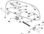
на Фиг.2 изображен первый вариант осуществления инъекционного устройства согласно настоящему изобретению,figure 2 shows a first embodiment of an injection device according to the present invention,
на Фиг.3 представлено изображение с пространственным разделением деталей механизма активации инъекционного устройства согласно Фиг.2,figure 3 presents the image with a spatial separation of the details of the activation mechanism of the injection device according to figure 2,
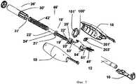
на Фиг.4 изображен второй вариант осуществления инъекционного устройства согласно настоящему изобретению,4 shows a second embodiment of an injection device according to the present invention,
на Фиг.5 представлено изображение с пространственным разделением деталей инъекционного устройства согласно Фиг.4.figure 5 presents the image with a spatial separation of the parts of the injection device according to figure 4.
ПОДРОБНОЕ ОПИСАНИЕ ИЗОБРЕТЕНИЯDETAILED DESCRIPTION OF THE INVENTION
На Фиг.2 изображен неограничивающий пример устройства для подачи лекарственного средства по настоящему изобретению. Устройство содержит корпус 10, сконструированный для работы одной рукой для многократного поэтапного введения малых количеств лекарственного средства. Внутри и с переднего конца корпуса расположен контейнер 12, содержащий лекарственное средство, имеющий передний край, на котором может быть прикреплено отверстие 14, например игла. Указанное устройство для подачи лекарственного средства содержит нажимный механизм, включающий в себя подвижную часть стенки, в дальнейшем называемую стопором, расположенную внутри контейнера; и нажимный элемент 18, такой как стержень поршня, предназначенный для проталкивания стопора вперед. Передний конец стержня поршня предпочтительно направлен от вращающего устройства для того, чтобы свести к минимуму трение между стержнем поршня и стопором.Figure 2 shows a non-limiting example of a device for dispensing a drug of the present invention. The device comprises a
Указанное устройство для подачи лекарственного средства также содержит приводное средство, включающее в себя элемент 42, аккумулирующий энергию, муфту 20 и привод 26.Said drug supply device also comprises a drive means including an
Подающее устройство по настоящему изобретению согласно первому варианту осуществления.A feed device of the present invention according to a first embodiment.
Фиг.2 и 3 относятся к первой конфигурации подающего устройства, в котором аккумулирующий энергию элемент 42 должен быть напряжен до начала введения лекарственного средства. Также муфта 20 приспособлена находиться в невращающемся состоянии благодаря двум выступающим наружу поворотным штифтам 23, установленным на оси в корпусе, в котором указанная муфта 20 имеет сквозное центральное отверстие 22 с резьбой, соответствующей резьбе стержня поршня. Привод 26 на Фиг.3 является полым, он располагается вокруг стержня поршня во вращательно запертом положении. Привод имеет нижнюю, первую, цилиндрическую переднюю секцию 28, на которой имеется ряд выступов 30, направленных наружу, расположенных с равными промежутками относительно друг друга вдоль окружности секции, где расстояние между двумя соседними выступами соответствует определенной, заранее установленной величине дозы; и вторую, удлиненную цилиндрическую секцию 32.FIGS. 2 and 3 relate to a first configuration of a delivery device in which the
Далее, элемент 42, аккумулирующий энергию, например плоская пружина, навинчен вокруг второй секции привода, причем внутренний конец элемента прикреплен к приводу 26. Ручка 44 регулировки напряжения расположена с заднего конца подающего устройства, к которому прикреплен внешний конец пружины 42.Further, an
Механизм 46 активации, как видно на Фиг.3, также расположен на подающем устройстве. Он включает в себя плечо 51, 51′, на котором расположена нажимная клавиша 48, выступающая сквозь щель на переднем конце корпуса, чтобы способствовать эргономичному управлению устройством. Клавиша прикрепляется к плечу 51 на боковой стороне контейнера и стержня поршня. На плече располагаются два выступающих наружу поворотных штифта 54, которые установлены на оси в корпусе. Задний край плеча содержит часть 52, имеющую форму крыла, на которой есть прорези 53. Промежуточный рычажок 100, частично располагающийся вокруг цилиндрической секции 32 привода 26, включает в себя два выступающих наружу поворотных штифта 101, размещающихся в прорезях 53, и горизонтальный выступ 102, предназначенный контактировать с одним из зубцов 202 на шестерне 200; в котором указанная шестерня также содержит штифты 201, установленные на оси в корпусе, и зубцы 203, расположенные с равными промежутками относительно друг друга вдоль окружности шестерни.The
При подготовке подающего устройства к использованию игла прикрепляется к контейнеру посредством подходящих средств, а защитный колпачок иглы удаляется. Ручка 44 регулировки напряжения затем приводится в действие, в соответствии с чем напрягается аккумулирующий энергию элемент 42. Привод лишен возможности поворачиваться из-за того, что один из зубцов 203 шестерни 200 находится в контакте с одним из выступов 30 привода, посредством чего привод удерживается от вращения.When preparing the feeder for use, the needle is attached to the container by suitable means, and the needle cap is removed. The
Когда необходимо ввести инъекцию, игла проникает через кожу в подходящем месте, и нажимается клавиша 48. Нажатие клавиши заставляет механизм активации вращаться вокруг поворотных штифтов 54. Это, в свою очередь, заставляет горизонтальный выступ 102 промежуточного рычажка 100 двигать шестерню 200, вследствие чего один из зубцов 203 шестерни 200, который находится в контакте с одним из выступов 30, выходит из контакта, и привод поворачивается на определенное шаговое расстояние, пока следующий зубец 203 шестерни 200 не войдет в контакт со следующим выступом 30 и, посредством этого приводное колесо не зафиксируется против вращения.When it is necessary to inject, the needle penetrates the skin in a suitable place, and the key 48 is pressed. Pressing the key causes the activation mechanism to rotate around the pivot pins 54. This, in turn, causes the
Вращение привода 26 вызывает вращение стержня 18 поршня. Благодаря усилию от элемента 42, аккумулирующего энергию, и резьбовому соединению между стержнем поршня и муфтой 20 стержень поршня перемещается вперед, надавливая на стопор, посредством чего лекарственное средство вытесняется через иглу.The rotation of the
Здесь необходимо обусловить, что расстояние между выступами 30 привода вместе с шагом резьбы стержня поршня соответствует определенной, заранее установленной величине дозы. То есть для того, чтобы задать точно определенную дозу, что осуществляется во время процесса производства устройства, выбирается определенное расстояние между выступами, а также определенный шаг резьбы стержня поршня. Данный механизм зубчатого зацепления приспособлен для подачи малых доз, особенно в пределах от 0,01 мл до 0,005 мл. Указанная первая конфигурация наиболее подходит для лекарственных препаратов или веществ, которые имеют высокую вязкость.Here it is necessary to determine that the distance between the
Подающее устройство по настоящему изобретению согласно второму варианту осуществленияA feed device of the present invention according to a second embodiment
Фиг.4 и 5 относятся ко второй конфигурации подающего устройства, в котором производитель поставляет устройство с аккумулирующим энергию элементом 42′ в предварительно напряженном состоянии. Привод 26′ указанной второй конфигурации имеет форму трубки с рядом выступов 30′, соответствующих шагу дозы, равномерно распределенных вдоль внешней окружности и имеющих продольные пазы 31′, равномерно распределенные вдоль внутренней окружности. Кроме того, стержень поршня 18′ указанной второй конфигурации имеет часть 19′ с резьбой и часть 25′ без резьбы, причем указанные части разделены диском 21′. Далее, указанный диск имеет выступы 24′ вдоль его окружности, соотнесенные с указанными продольными пазами 31′ указанного привода, так что стержень поршня, проходя через привод, не способен вращаться, но способен скользить. Муфта 20' приспособлена находиться в невращающемся состоянии благодаря двум выступающим наружу поворотным штифтам 23′, установленным на оси в корпусе. Указанная муфта 20′ также имеет сквозное центральное отверстие 22′ с резьбой, соответствующей резьбе на части 19′ стержня поршня. Аккумулирующий энергию элемент 42′ расположен внутри указанного привода 26′ между внутренней поверхностью дистального конца указанного привода 26′ и задним краем диска 21′.4 and 5 relate to the second configuration of the feeding device, in which the manufacturer supplies the device with the
Механизм 46′ активации, как видно на Фиг.5, также расположен на подающем устройстве, в котором указанный механизм 46′ активации содержит клавишу 48′, выступающую сквозь щель на переднем конце корпуса, чтобы способствовать эргономичному управлению устройством. Клавиша прикрепляется к плечу 51′ на боковой стороне контейнера и стержня поршня. На плече располагаются два выступающих наружу поворотных штифта 54′, которые установлены на оси в корпусе. Задний край плеча содержит часть 52′, имеющую форму крыла, на которой есть прорези 53′. Промежуточный рычажок 100′, имеющий больший диаметр, чем внешний диаметр привода 26′, располагается вокруг внешней поверхности указанного привода 26′. Далее, указанный промежуточный рычажок 100′ включает в себя два выступающих наружу поворотных штифта 101′, размещающихся в прорезях 53′, и горизонтальный выступ 102′, предназначенный контактировать с одним из зубцов 202′ на шестерне 200′, в котором указанная шестерня также содержит штифты 201′, установленные на оси в корпусе, и зубцы 203′, расположенные с равными промежутками относительно друг друга вдоль окружности шестерни. Пружинный элемент 300′, например цилиндрическая пружина, расположен между щелью на корпусе и щелью на рычажке 100′, как видно на Фиг.4.The
При подготовке подающего устройства к использованию игла прикрепляется к контейнеру посредством подходящих средств, а защитный колпачок иглы удаляется. Привод лишен возможности поворачиваться из-за того, что один из зубцов 203′ шестерни 200′ находится в контакте с одним из выступов 30′ привода, посредством чего привод удерживается от вращения.When preparing the feeder for use, the needle is attached to the container by suitable means, and the needle cap is removed. The drive is unable to rotate due to the fact that one of the
Когда необходимо ввести инъекцию, игла проникает через кожу в подходящем месте, и нажимается клавиша 48′. Нажатие клавиши заставляет механизм активации вращаться вокруг поворотных штифтов 54′. Это, в свою очередь, заставляет горизонтальный выступ 102′ промежуточного рычажка 100′ двигать шестерню 200′, вследствие чего один из зубцов 203′ шестерни 200′, который находится в контакте с одним из выступов 30′, выходит из контакта, и привод поворачивается на определенное шаговое расстояние, пока следующий зубец 203′ шестерни 200′ не войдет в контакт со следующим выступом 30′, и посредством этого приводное колесо не зафиксируется против вращения.When an injection is necessary, the needle penetrates the skin in a suitable place and the 48 ′ key is pressed. Pressing the key causes the activation mechanism to rotate around the pivot pins 54 ′. This, in turn, causes the
Вращение привода 26′ вызывает вращение стержня 18′ поршня. Благодаря усилию от элемента 42′, аккумулирующего энергию, и резьбовому соединению между частью 19′ с резьбой стержня поршня и муфтой 20′ стержень поршня перемещается вперед, надавливая на стопор, посредством чего лекарственное средство вытесняется через иглу.The rotation of the actuator 26 ′ causes the rotation of the
Здесь необходимо обусловить, что расстояние между выступами 30′ привода вместе с шагом резьбы части 19′ стержня поршня соответствует определенной, заранее установленной величине дозы. То есть для того, чтобы задать точно определенную дозу, что осуществляется во время процесса производства устройства, выбирается определенное расстояние между выступами, а также определенный шаг резьбы стержня поршня.Here it is necessary to determine that the distance between the
Указанная вторая конфигурация наиболее подходит для лекарственных препаратов или веществ, которые имеют низкую вязкость.The specified second configuration is most suitable for drugs or substances that have a low viscosity.
Кроме того, в вариантах конструкции, предпочтительных на сегодняшний день, расстояния приращения шага дозы находятся в пределах от 0,01 мл до 0,005 мл на шаг, и одно приращение шага дозы в 0,01 мл соответствует вращению приводного колеса по часовой стрелке на 45°.In addition, in the preferred designs today, the increments of the increment of the dose step are in the range of 0.01 ml to 0.005 ml per step, and one increment of the dose increment of 0.01 ml corresponds to a 45 ° clockwise rotation of the drive wheel .
Здесь необходимо обусловить, что варианты осуществления, описанные выше и показанные на чертежах, следует рассматривать только как неограничивающие примеры данного изобретения, и что они могут быть модифицированы различными способами в рамках масштаба пунктов формулы изобретения.Here it is necessary to stipulate that the embodiments described above and shown in the drawings should be considered only as non-limiting examples of the present invention, and that they can be modified in various ways within the scope of the claims.
Claims (8)
Translated fromRussianApplications Claiming Priority (2)
| Application Number | Priority Date | Filing Date | Title |
|---|---|---|---|
| SE0701553-0 | 2007-06-19 | ||
| SE0701553 | 2007-06-19 |
Publications (1)
| Publication Number | Publication Date |
|---|---|
| RU2434651C1true RU2434651C1 (en) | 2011-11-27 |
Family
ID=39617798
Family Applications (1)
| Application Number | Title | Priority Date | Filing Date |
|---|---|---|---|
| RU2010119944/14ARU2434651C1 (en) | 2007-06-19 | 2008-04-15 | Device for medication supply |
Country Status (10)
| Country | Link |
|---|---|
| US (1) | US8376997B2 (en) |
| EP (1) | EP2192939B1 (en) |
| AT (1) | ATE501752T1 (en) |
| AU (1) | AU2008266458B2 (en) |
| CA (1) | CA2702412C (en) |
| DE (1) | DE602008005616D1 (en) |
| DK (1) | DK2192939T3 (en) |
| ES (1) | ES2362756T3 (en) |
| RU (1) | RU2434651C1 (en) |
| WO (1) | WO2008155144A1 (en) |
Families Citing this family (39)
| Publication number | Priority date | Publication date | Assignee | Title |
|---|---|---|---|---|
| WO2003068290A2 (en) | 2002-02-11 | 2003-08-21 | Antares Pharma, Inc. | Intradermal injector |
| HUE042286T2 (en) | 2005-01-24 | 2019-06-28 | Antares Pharma Inc | Needle-filled pre-filled syringe |
| WO2007131013A1 (en) | 2006-05-03 | 2007-11-15 | Antares Pharma, Inc. | Two-stage reconstituting injector |
| WO2007131025A1 (en) | 2006-05-03 | 2007-11-15 | Antares Pharma, Inc. | Injector with adjustable dosing |
| EP3636301A1 (en) | 2008-03-10 | 2020-04-15 | Antares Pharma, Inc. | Injector safety device |
| US8376993B2 (en) | 2008-08-05 | 2013-02-19 | Antares Pharma, Inc. | Multiple dosage injector |
| JP5732039B2 (en) | 2009-03-20 | 2015-06-10 | アンタレス・ファーマ・インコーポレーテッド | Hazardous drug injection system |
| SE0900371A1 (en)* | 2009-03-24 | 2010-09-25 | Istvan Bartha | Device for distribution of liquid drugs |
| GB0918145D0 (en)* | 2009-10-16 | 2009-12-02 | Owen Mumford Ltd | Injector apparatus |
| WO2011101349A1 (en)* | 2010-02-17 | 2011-08-25 | Sanofi-Aventis Deutschland Gmbh | Automatic injection device with torsional spring |
| DK2536452T3 (en) | 2010-02-18 | 2019-01-02 | Sanofi Aventis Deutschland | autoinjector |
| WO2011133089A1 (en)* | 2010-04-19 | 2011-10-27 | Shl Group Ab | A self-administration medicament delivery device |
| EP2399635A1 (en) | 2010-06-28 | 2011-12-28 | Sanofi-Aventis Deutschland GmbH | Auto-injector |
| GB201015799D0 (en)* | 2010-09-21 | 2010-10-27 | Owen Mumford Ltd | Autoinjectors |
| EP2468333A1 (en) | 2010-12-21 | 2012-06-27 | Sanofi-Aventis Deutschland GmbH | Auto-injector |
| EP2468330A1 (en) | 2010-12-21 | 2012-06-27 | Sanofi-Aventis Deutschland GmbH | Auto-injector |
| USRE48593E1 (en) | 2010-12-21 | 2021-06-15 | Sanofi-Aventis Deutschland Gmbh | Auto-injector |
| US8535268B2 (en) | 2010-12-22 | 2013-09-17 | Alcon Research, Ltd. | Device for at least one of injection or aspiration |
| EP2489385A1 (en) | 2011-02-18 | 2012-08-22 | Sanofi-Aventis Deutschland GmbH | Auto-injector |
| US8496619B2 (en) | 2011-07-15 | 2013-07-30 | Antares Pharma, Inc. | Injection device with cammed ram assembly |
| US9220660B2 (en) | 2011-07-15 | 2015-12-29 | Antares Pharma, Inc. | Liquid-transfer adapter beveled spike |
| EP2606924A1 (en) | 2011-12-21 | 2013-06-26 | Sanofi-Aventis Deutschland GmbH | Autoinjector having a retracting syringe carrier |
| US9486583B2 (en) | 2012-03-06 | 2016-11-08 | Antares Pharma, Inc. | Prefilled syringe with breakaway force feature |
| EP4186545A1 (en) | 2012-04-06 | 2023-05-31 | Antares Pharma, Inc. | Needle assisted jet injection administration of testosterone compositions |
| US9364610B2 (en) | 2012-05-07 | 2016-06-14 | Antares Pharma, Inc. | Injection device with cammed ram assembly |
| FI3659647T3 (en) | 2013-02-11 | 2024-03-28 | Antares Pharma Inc | NEEDLE-ASSISTED SPRAY INJECTOR WITH REDUCED TRIGGER FORCE |
| CA2905031C (en) | 2013-03-11 | 2018-01-23 | Hans PFLAUMER | Dosage injector with pinion system |
| WO2014165136A1 (en) | 2013-03-12 | 2014-10-09 | Antares Pharma, Inc. | Constant volume prefilled syringes and kits thereof |
| EP2823841A1 (en) | 2013-07-09 | 2015-01-14 | Sanofi-Aventis Deutschland GmbH | Autoinjector |
| JP2016537111A (en)* | 2013-11-20 | 2016-12-01 | ノボ・ノルデイスク・エー/エス | Drive mechanism for injection device |
| US8985394B1 (en)* | 2013-11-22 | 2015-03-24 | Bryan Tapocik | Pen removably retaining single use capsule containing tooth whitening compounds, dental bonding compounds and adhesives and removably retaining disposable tooth whitening applicators, disposable dental bonding compound applicators and disposable adhesive applicators |
| EP2923714A1 (en) | 2014-03-28 | 2015-09-30 | Sanofi-Aventis Deutschland GmbH | Autoinjector triggered by skin contact |
| US9707052B2 (en)* | 2015-01-29 | 2017-07-18 | Bryan Tapocik | Mechanical pen with improvements for pen removably retaining single use capsule containing tooth whitening compounds, dental bonding compounds and adhesives and removably retaining disposable tooth whitening applicators, disposable dental bonding compound applicators and disposable adhesive applicators |
| US9572646B2 (en) | 2015-03-20 | 2017-02-21 | Bryan Tapocik | Electrical pen with improvements for pen removably retaining single use cartridge containing tooth whitening compounds, dental bonding compounds, nail polish, and adhesives and removably retaining disposable tooth whitening applicators, disposable dental bonding compound applicators, nail polish applicators and disposable adhesive applicators |
| TW201707738A (en) | 2015-06-03 | 2017-03-01 | 賽諾菲阿凡提斯德意志有限公司 | Syringe holder and autoinjector (2) |
| PL227678B1 (en) | 2015-12-22 | 2018-01-31 | Copernicus Spolka Z Ograniczona Odpowiedzialnoscia | Control and drive system for the device intended for injection and the device for making injections equipped with such a system |
| PL3108914T3 (en) | 2016-07-07 | 2019-08-30 | Copernicus Sp. Z O.O. | Injection device for delivering a defined number of equal doses of a liquid substance |
| PL232651B1 (en) | 2017-07-18 | 2019-07-31 | Copernicus Spolka Z Ograniczona Odpowiedzialnoscia | Coupling with locking system for the medical injecting device |
| US10391253B1 (en) | 2018-06-19 | 2019-08-27 | Innomed Technologies, Inc. | Precision low-dose, low-waste syringes and ergonomic attachments therefor |
Citations (4)
| Publication number | Priority date | Publication date | Assignee | Title |
|---|---|---|---|---|
| US4659327A (en)* | 1985-11-26 | 1987-04-21 | Dentsply Research & Development Corp. | Multiple dosage syringe |
| WO2002053214A1 (en)* | 2001-01-05 | 2002-07-11 | Novo Nordisk A/S | Automatic injection device with reset feature |
| RU2197997C2 (en)* | 1996-07-01 | 2003-02-10 | Фармациа Энд Апджон Аб | Device and method for making injections |
| RU2270035C2 (en)* | 2001-07-30 | 2006-02-20 | Текфарма Лайсензинг Аг | Injection apparatus comprising rotation preventing unit |
Family Cites Families (5)
| Publication number | Priority date | Publication date | Assignee | Title |
|---|---|---|---|---|
| SE9901736D0 (en)* | 1999-05-12 | 1999-05-12 | Pharmacia & Upjohn Ab | Injectino device and method for ITS operation |
| US6716198B2 (en) | 2000-05-18 | 2004-04-06 | Novo Nordisk A/S | Injection device |
| NZ542864A (en) | 2003-04-16 | 2008-04-30 | Allergan Inc | Controlled volume injection/aspiration device |
| EP1732629B1 (en) | 2004-03-30 | 2019-04-24 | Eli Lilly And Company | Medication dispensing apparatus with spring-driven locking feature enabled by administration of final dose |
| WO2006020756A2 (en) | 2004-08-10 | 2006-02-23 | Allergan, Inc. | Step by step botox injector |
- 2008
- 2008-04-15CACA2702412Apatent/CA2702412C/enactiveActive
- 2008-04-15EPEP08736240Apatent/EP2192939B1/enactiveActive
- 2008-04-15RURU2010119944/14Apatent/RU2434651C1/enactive
- 2008-04-15ATAT08736240Tpatent/ATE501752T1/enactive
- 2008-04-15USUS12/679,583patent/US8376997B2/enactiveActive
- 2008-04-15WOPCT/EP2008/054548patent/WO2008155144A1/enactiveApplication Filing
- 2008-04-15DEDE602008005616Tpatent/DE602008005616D1/enactiveActive
- 2008-04-15ESES08736240Tpatent/ES2362756T3/enactiveActive
- 2008-04-15AUAU2008266458Apatent/AU2008266458B2/ennot_activeCeased
- 2008-04-15DKDK08736240.6Tpatent/DK2192939T3/enactive
Patent Citations (4)
| Publication number | Priority date | Publication date | Assignee | Title |
|---|---|---|---|---|
| US4659327A (en)* | 1985-11-26 | 1987-04-21 | Dentsply Research & Development Corp. | Multiple dosage syringe |
| RU2197997C2 (en)* | 1996-07-01 | 2003-02-10 | Фармациа Энд Апджон Аб | Device and method for making injections |
| WO2002053214A1 (en)* | 2001-01-05 | 2002-07-11 | Novo Nordisk A/S | Automatic injection device with reset feature |
| RU2270035C2 (en)* | 2001-07-30 | 2006-02-20 | Текфарма Лайсензинг Аг | Injection apparatus comprising rotation preventing unit |
Also Published As
| Publication number | Publication date |
|---|---|
| ES2362756T3 (en) | 2011-07-12 |
| AU2008266458B2 (en) | 2011-11-10 |
| DE602008005616D1 (en) | 2011-04-28 |
| EP2192939A1 (en) | 2010-06-09 |
| WO2008155144A1 (en) | 2008-12-24 |
| AU2008266458A1 (en) | 2008-12-24 |
| US8376997B2 (en) | 2013-02-19 |
| EP2192939B1 (en) | 2011-03-16 |
| CA2702412A1 (en) | 2008-12-24 |
| DK2192939T3 (en) | 2011-06-14 |
| CA2702412C (en) | 2012-07-17 |
| ATE501752T1 (en) | 2011-04-15 |
| US20100298781A1 (en) | 2010-11-25 |
Similar Documents
| Publication | Publication Date | Title |
|---|---|---|
| RU2434651C1 (en) | Device for medication supply | |
| RU2556965C2 (en) | Device for injection of set liquid medication dose | |
| JP6359774B2 (en) | Dose setting mechanism and drug delivery device including dose setting mechanism | |
| DK2051753T3 (en) | DEVICE FOR THE DELIVERY OF MEDICINALS, INCLUDING A PRESSURE RELEASE MECHANISM | |
| EP2328642B1 (en) | Medicament delivery device | |
| JP4791977B2 (en) | Retractable dose setting knob | |
| EP1843808B1 (en) | Device for delivering medicament | |
| JP4302627B2 (en) | Product supply device with quick reset function of piston rod | |
| RU2534609C2 (en) | Drug delivery device | |
| JP4897920B2 (en) | Counter-rotatable dose setting mechanism for injection devices | |
| US7976509B2 (en) | Injection device with secured dosing button | |
| JP2010104804A (en) | Device for administration of injectable drug product | |
| JP2004535902A (en) | Reservoir module with piston rod | |
| JP2006507035A (en) | Injection device | |
| JP2004535904A (en) | Dosing device provided with rotation preventing part | |
| CN105899248A (en) | Auto-injection device with button activation | |
| CN107787237B (en) | Drug delivery device | |
| CN101370541B (en) | Injection device with fixed dosing knob | |
| RU2575549C2 (en) | Preset liquid drug dose injector (versions) | |
| CN115484998A (en) | Activatable drug delivery device with safety components | |
| US20190022329A1 (en) | Medicament Delivery Device |
Legal Events
| Date | Code | Title | Description |
|---|---|---|---|
| PC41 | Official registration of the transfer of exclusive right | Effective date:20191212 |