RU2429887C2 - External exposure system and method of using it - Google Patents
External exposure system and method of using itDownload PDFInfo
- Publication number
- RU2429887C2 RU2429887C2RU2008109838/14ARU2008109838ARU2429887C2RU 2429887 C2RU2429887 C2RU 2429887C2RU 2008109838/14 ARU2008109838/14 ARU 2008109838/14ARU 2008109838 ARU2008109838 ARU 2008109838ARU 2429887 C2RU2429887 C2RU 2429887C2
- Authority
- RU
- Russia
- Prior art keywords
- specified
- wound
- component
- incision
- fluid
- Prior art date
Links
- 238000000034methodMethods0.000titleclaimsabstractdescription46
- 239000012530fluidSubstances0.000claimsabstractdescription128
- 206010052428WoundDiseases0.000claimsabstractdescription111
- 208000027418Wounds and injuryDiseases0.000claimsabstractdescription110
- 239000002250absorbentSubstances0.000claimsabstractdescription33
- 230000002745absorbentEffects0.000claimsabstractdescription33
- 239000002874hemostatic agentSubstances0.000claimsabstractdescription9
- 229940030225antihemorrhagicsDrugs0.000claimsabstract2
- 238000012546transferMethods0.000claimsdescription91
- 239000000463materialSubstances0.000claimsdescription63
- 229920000297RayonPolymers0.000claimsdescription40
- 239000007788liquidSubstances0.000claimsdescription27
- 239000004744fabricSubstances0.000claimsdescription25
- 238000007920subcutaneous administrationMethods0.000claimsdescription17
- 239000011248coating agentSubstances0.000claimsdescription15
- 238000000576coating methodMethods0.000claimsdescription15
- 239000006261foam materialSubstances0.000claimsdescription12
- RTZKZFJDLAIYFH-UHFFFAOYSA-NDiethyl etherChemical compoundCCOCCRTZKZFJDLAIYFH-UHFFFAOYSA-N0.000claimsdescription11
- 239000003795chemical substances by applicationSubstances0.000claimsdescription11
- 229920002635polyurethanePolymers0.000claimsdescription7
- 239000004814polyurethaneSubstances0.000claimsdescription7
- 238000004891communicationMethods0.000claimsdescription5
- 230000003993interactionEffects0.000claimsdescription2
- 238000007599dischargingMethods0.000claims2
- 244000208060Lawsonia inermisSpecies0.000claims1
- 230000023597hemostasisEffects0.000claims1
- 239000011118polyvinyl acetateSubstances0.000claims1
- 208000002847Surgical WoundDiseases0.000abstractdescription13
- 230000000694effectsEffects0.000abstractdescription10
- 239000003814drugSubstances0.000abstractdescription3
- 239000000126substanceSubstances0.000abstractdescription2
- 230000037314wound repairEffects0.000abstract1
- 210000001519tissueAnatomy0.000description83
- 239000006260foamSubstances0.000description59
- 210000003491skinAnatomy0.000description44
- 239000010410layerSubstances0.000description39
- 230000035876healingEffects0.000description26
- 238000007906compressionMethods0.000description23
- 230000006835compressionEffects0.000description23
- 238000007789sealingMethods0.000description15
- 238000001356surgical procedureMethods0.000description13
- 239000003570airSubstances0.000description11
- 230000008901benefitEffects0.000description11
- 210000000416exudates and transudateAnatomy0.000description11
- 230000002980postoperative effectEffects0.000description11
- 238000010521absorption reactionMethods0.000description10
- 238000002224dissectionMethods0.000description10
- 239000000853adhesiveSubstances0.000description9
- 230000001070adhesive effectEffects0.000description9
- 230000002209hydrophobic effectEffects0.000description9
- 230000033001locomotionEffects0.000description9
- 208000032843HemorrhageDiseases0.000description8
- 206010030113OedemaDiseases0.000description8
- 239000012790adhesive layerSubstances0.000description8
- 230000015572biosynthetic processEffects0.000description8
- 210000004207dermisAnatomy0.000description8
- 238000005755formation reactionMethods0.000description8
- 230000000740bleeding effectEffects0.000description7
- 208000015181infectious diseaseDiseases0.000description7
- 230000036961partial effectEffects0.000description7
- 206010042674SwellingDiseases0.000description6
- 230000008961swellingEffects0.000description6
- 239000012080ambient airSubstances0.000description5
- 210000004369bloodAnatomy0.000description5
- 239000008280bloodSubstances0.000description5
- 230000001276controlling effectEffects0.000description5
- 238000013461designMethods0.000description5
- 210000001503jointAnatomy0.000description5
- 230000000670limiting effectEffects0.000description5
- 210000004379membraneAnatomy0.000description5
- 239000012528membraneSubstances0.000description5
- 230000001681protective effectEffects0.000description5
- 230000006641stabilisationEffects0.000description5
- 238000011105stabilizationMethods0.000description5
- 241000894006BacteriaSpecies0.000description4
- 239000003242anti bacterial agentSubstances0.000description4
- 229940088710antibiotic agentDrugs0.000description4
- 230000009286beneficial effectEffects0.000description4
- 210000003414extremityAnatomy0.000description4
- 210000003195fasciaAnatomy0.000description4
- 206010033675panniculitisDiseases0.000description4
- 210000004304subcutaneous tissueAnatomy0.000description4
- 102000008186CollagenHuman genes0.000description3
- 108010035532CollagenProteins0.000description3
- 229920005830Polyurethane FoamPolymers0.000description3
- 210000000988bone and boneAnatomy0.000description3
- 238000001444catalytic combustion detectionMethods0.000description3
- 238000006243chemical reactionMethods0.000description3
- 229920001436collagenPolymers0.000description3
- 238000002316cosmetic surgeryMethods0.000description3
- 238000005520cutting processMethods0.000description3
- 238000010586diagramMethods0.000description3
- 238000005516engineering processMethods0.000description3
- 238000011010flushing procedureMethods0.000description3
- 230000006870functionEffects0.000description3
- 239000003102growth factorSubstances0.000description3
- 230000036074healthy skinEffects0.000description3
- 210000003127kneeAnatomy0.000description3
- 238000002803macerationMethods0.000description3
- 230000036407painEffects0.000description3
- 239000011496polyurethane foamSubstances0.000description3
- 239000011148porous materialSubstances0.000description3
- 238000002278reconstructive surgeryMethods0.000description3
- 230000009467reductionEffects0.000description3
- 238000002271resectionMethods0.000description3
- 231100000241scarToxicity0.000description3
- 210000004911serous fluidAnatomy0.000description3
- 238000011179visual inspectionMethods0.000description3
- 238000005406washingMethods0.000description3
- 208000032544CicatrixDiseases0.000description2
- 208000034656ContusionsDiseases0.000description2
- 206010018852HaematomaDiseases0.000description2
- 206010018999Haemorrhage subcutaneousDiseases0.000description2
- 206010048625Skin macerationDiseases0.000description2
- 230000009471actionEffects0.000description2
- 239000002313adhesive filmSubstances0.000description2
- 230000000844anti-bacterial effectEffects0.000description2
- 230000002421anti-septic effectEffects0.000description2
- 210000001124body fluidAnatomy0.000description2
- 230000012292cell migrationEffects0.000description2
- 230000008602contractionEffects0.000description2
- 238000012937correctionMethods0.000description2
- 238000006073displacement reactionMethods0.000description2
- 230000002500effect on skinEffects0.000description2
- 210000002310elbow jointAnatomy0.000description2
- 230000008030eliminationEffects0.000description2
- 238000003379elimination reactionMethods0.000description2
- 210000005081epithelial layerAnatomy0.000description2
- 230000012010growthEffects0.000description2
- 238000007689inspectionMethods0.000description2
- 230000007774longtermEffects0.000description2
- 238000004519manufacturing processMethods0.000description2
- 230000007246mechanismEffects0.000description2
- 210000003205muscleAnatomy0.000description2
- 230000017074necrotic cell deathEffects0.000description2
- 230000000399orthopedic effectEffects0.000description2
- 230000035699permeabilityEffects0.000description2
- 230000001737promoting effectEffects0.000description2
- 239000011241protective layerSubstances0.000description2
- 108090000623proteins and genesProteins0.000description2
- 102000004169proteins and genesHuman genes0.000description2
- 239000002964rayonSubstances0.000description2
- 230000001105regulatory effectEffects0.000description2
- 230000037390scarringEffects0.000description2
- 230000037387scarsEffects0.000description2
- 230000001225therapeutic effectEffects0.000description2
- 230000000472traumatic effectEffects0.000description2
- 238000009423ventilationMethods0.000description2
- 230000029663wound healingEffects0.000description2
- BSWWXRFVMJHFBN-UHFFFAOYSA-N2,4,6-tribromophenolChemical compoundOC1=C(Br)C=C(Br)C=C1BrBSWWXRFVMJHFBN-UHFFFAOYSA-N0.000description1
- 206010002091AnaesthesiaDiseases0.000description1
- 206010003694AtrophyDiseases0.000description1
- 206010057687Bloody dischargeDiseases0.000description1
- 208000010392Bone FracturesDiseases0.000description1
- 206010014080EcchymosisDiseases0.000description1
- 206010015866ExtravasationDiseases0.000description1
- 102000001554HemoglobinsHuman genes0.000description1
- 108010054147HemoglobinsProteins0.000description1
- 206010028980NeoplasmDiseases0.000description1
- 239000004698PolyethyleneSubstances0.000description1
- 241000220324PyrusSpecies0.000description1
- 241000220010RhodeSpecies0.000description1
- 208000033809SuppurationDiseases0.000description1
- 230000003187abdominal effectEffects0.000description1
- 230000006978adaptationEffects0.000description1
- 239000002390adhesive tapeSubstances0.000description1
- 210000000577adipose tissueAnatomy0.000description1
- 238000002266amputationMethods0.000description1
- 230000037005anaesthesiaEffects0.000description1
- 238000004458analytical methodMethods0.000description1
- 230000000845anti-microbial effectEffects0.000description1
- 229940064004antiseptic throat preparationsDrugs0.000description1
- 230000037444atrophyEffects0.000description1
- 238000011888autopsyMethods0.000description1
- 230000008953bacterial degradationEffects0.000description1
- 238000005452bendingMethods0.000description1
- 208000034158bleedingDiseases0.000description1
- 239000010839body fluidSubstances0.000description1
- 230000008859changeEffects0.000description1
- 239000003153chemical reaction reagentSubstances0.000description1
- 210000000038chestAnatomy0.000description1
- 230000001684chronic effectEffects0.000description1
- 238000004140cleaningMethods0.000description1
- 238000005056compactionMethods0.000description1
- 239000012141concentrateSubstances0.000description1
- 238000012790confirmationMethods0.000description1
- 238000010276constructionMethods0.000description1
- 239000000356contaminantSubstances0.000description1
- 239000002537cosmeticSubstances0.000description1
- 101150008740cpg-1 geneProteins0.000description1
- 101150071119cpg-2 geneProteins0.000description1
- 125000004122cyclic groupChemical group0.000description1
- 230000006837decompressionEffects0.000description1
- 238000000280densificationMethods0.000description1
- 230000001066destructive effectEffects0.000description1
- 238000011161developmentMethods0.000description1
- 206010012601diabetes mellitusDiseases0.000description1
- 238000003745diagnosisMethods0.000description1
- 238000012279drainage procedureMethods0.000description1
- 210000001513elbowAnatomy0.000description1
- 230000007613environmental effectEffects0.000description1
- 210000002615epidermisAnatomy0.000description1
- 150000002148estersChemical class0.000description1
- 238000011156evaluationMethods0.000description1
- 238000001704evaporationMethods0.000description1
- 230000008020evaporationEffects0.000description1
- 230000036251extravasationEffects0.000description1
- 210000003608feceAnatomy0.000description1
- 210000002683footAnatomy0.000description1
- 230000036541healthEffects0.000description1
- 230000002439hemostatic effectEffects0.000description1
- 239000007943implantSubstances0.000description1
- 230000006872improvementEffects0.000description1
- 230000002458infectious effectEffects0.000description1
- 238000001802infusionMethods0.000description1
- 230000005764inhibitory processEffects0.000description1
- 208000014674injuryDiseases0.000description1
- 238000009434installationMethods0.000description1
- 230000002452interceptive effectEffects0.000description1
- 230000007794irritationEffects0.000description1
- 238000002955isolationMethods0.000description1
- 238000005304joiningMethods0.000description1
- 230000008407joint functionEffects0.000description1
- 239000004816latexSubstances0.000description1
- 229920000126latexPolymers0.000description1
- 239000002346layers by functionSubstances0.000description1
- 210000002414legAnatomy0.000description1
- 239000006210lotionSubstances0.000description1
- 230000003446memory effectEffects0.000description1
- 238000012544monitoring processMethods0.000description1
- 235000021017pearsNutrition0.000description1
- 230000000737periodic effectEffects0.000description1
- 239000002831pharmacologic agentSubstances0.000description1
- 230000000144pharmacologic effectEffects0.000description1
- 239000011505plasterSubstances0.000description1
- -1polyethylenePolymers0.000description1
- 229920000573polyethylenePolymers0.000description1
- 238000003825pressingMethods0.000description1
- 230000002265preventionEffects0.000description1
- 230000008569processEffects0.000description1
- 230000002035prolonged effectEffects0.000description1
- 238000005086pumpingMethods0.000description1
- 238000000746purificationMethods0.000description1
- 230000002829reductive effectEffects0.000description1
- 230000004044responseEffects0.000description1
- 230000000452restraining effectEffects0.000description1
- 230000037307sensitive skinEffects0.000description1
- 238000000926separation methodMethods0.000description1
- 210000002832shoulderAnatomy0.000description1
- 238000002791soakingMethods0.000description1
- 230000000087stabilizing effectEffects0.000description1
- 230000001629suppressionEffects0.000description1
- 238000011477surgical interventionMethods0.000description1
- 239000003356suture materialSubstances0.000description1
- 230000009897systematic effectEffects0.000description1
- 210000000115thoracic cavityAnatomy0.000description1
- 230000008467tissue growthEffects0.000description1
- 230000000699topical effectEffects0.000description1
- 239000003053toxinSubstances0.000description1
- 231100000765toxinToxicity0.000description1
- 108700012359toxinsProteins0.000description1
- 230000007704transitionEffects0.000description1
- 230000008736traumatic injuryEffects0.000description1
- 238000009966trimmingMethods0.000description1
- 210000000689upper legAnatomy0.000description1
- 210000002700urineAnatomy0.000description1
- 229940099259vaselineDrugs0.000description1
- 210000001835visceraAnatomy0.000description1
- 230000000007visual effectEffects0.000description1
- 239000002699waste materialSubstances0.000description1
- XLYOFNOQVPJJNP-UHFFFAOYSA-NwaterSubstancesOXLYOFNOQVPJJNP-UHFFFAOYSA-N0.000description1
Images


Classifications
- A—HUMAN NECESSITIES
- A61—MEDICAL OR VETERINARY SCIENCE; HYGIENE
- A61F—FILTERS IMPLANTABLE INTO BLOOD VESSELS; PROSTHESES; DEVICES PROVIDING PATENCY TO, OR PREVENTING COLLAPSING OF, TUBULAR STRUCTURES OF THE BODY, e.g. STENTS; ORTHOPAEDIC, NURSING OR CONTRACEPTIVE DEVICES; FOMENTATION; TREATMENT OR PROTECTION OF EYES OR EARS; BANDAGES, DRESSINGS OR ABSORBENT PADS; FIRST-AID KITS
- A61F13/00—Bandages or dressings; Absorbent pads
- A61F13/02—Adhesive bandages or dressings
- A61F13/0203—Adhesive bandages or dressings with fluid retention members
- A61F13/022—Adhesive bandages or dressings with fluid retention members having more than one layer with different fluid retention characteristics
- A—HUMAN NECESSITIES
- A61—MEDICAL OR VETERINARY SCIENCE; HYGIENE
- A61F—FILTERS IMPLANTABLE INTO BLOOD VESSELS; PROSTHESES; DEVICES PROVIDING PATENCY TO, OR PREVENTING COLLAPSING OF, TUBULAR STRUCTURES OF THE BODY, e.g. STENTS; ORTHOPAEDIC, NURSING OR CONTRACEPTIVE DEVICES; FOMENTATION; TREATMENT OR PROTECTION OF EYES OR EARS; BANDAGES, DRESSINGS OR ABSORBENT PADS; FIRST-AID KITS
- A61F13/00—Bandages or dressings; Absorbent pads
- A61F13/02—Adhesive bandages or dressings
- A61F13/0203—Adhesive bandages or dressings with fluid retention members
- A—HUMAN NECESSITIES
- A61—MEDICAL OR VETERINARY SCIENCE; HYGIENE
- A61F—FILTERS IMPLANTABLE INTO BLOOD VESSELS; PROSTHESES; DEVICES PROVIDING PATENCY TO, OR PREVENTING COLLAPSING OF, TUBULAR STRUCTURES OF THE BODY, e.g. STENTS; ORTHOPAEDIC, NURSING OR CONTRACEPTIVE DEVICES; FOMENTATION; TREATMENT OR PROTECTION OF EYES OR EARS; BANDAGES, DRESSINGS OR ABSORBENT PADS; FIRST-AID KITS
- A61F13/00—Bandages or dressings; Absorbent pads
- A61F13/05—Bandages or dressings; Absorbent pads specially adapted for use with sub-pressure or over-pressure therapy, wound drainage or wound irrigation, e.g. for use with negative-pressure wound therapy [NPWT]
- A—HUMAN NECESSITIES
- A61—MEDICAL OR VETERINARY SCIENCE; HYGIENE
- A61M—DEVICES FOR INTRODUCING MEDIA INTO, OR ONTO, THE BODY; DEVICES FOR TRANSDUCING BODY MEDIA OR FOR TAKING MEDIA FROM THE BODY; DEVICES FOR PRODUCING OR ENDING SLEEP OR STUPOR
- A61M1/00—Suction or pumping devices for medical purposes; Devices for carrying-off, for treatment of, or for carrying-over, body-liquids; Drainage systems
- A61M1/71—Suction drainage systems
- A61M1/73—Suction drainage systems comprising sensors or indicators for physical values
- A61M1/732—Visual indicating means for vacuum pressure
- A—HUMAN NECESSITIES
- A61—MEDICAL OR VETERINARY SCIENCE; HYGIENE
- A61M—DEVICES FOR INTRODUCING MEDIA INTO, OR ONTO, THE BODY; DEVICES FOR TRANSDUCING BODY MEDIA OR FOR TAKING MEDIA FROM THE BODY; DEVICES FOR PRODUCING OR ENDING SLEEP OR STUPOR
- A61M1/00—Suction or pumping devices for medical purposes; Devices for carrying-off, for treatment of, or for carrying-over, body-liquids; Drainage systems
- A61M1/71—Suction drainage systems
- A61M1/73—Suction drainage systems comprising sensors or indicators for physical values
- A61M1/734—Visual indicating means for flow
- A—HUMAN NECESSITIES
- A61—MEDICAL OR VETERINARY SCIENCE; HYGIENE
- A61M—DEVICES FOR INTRODUCING MEDIA INTO, OR ONTO, THE BODY; DEVICES FOR TRANSDUCING BODY MEDIA OR FOR TAKING MEDIA FROM THE BODY; DEVICES FOR PRODUCING OR ENDING SLEEP OR STUPOR
- A61M1/00—Suction or pumping devices for medical purposes; Devices for carrying-off, for treatment of, or for carrying-over, body-liquids; Drainage systems
- A61M1/71—Suction drainage systems
- A61M1/74—Suction control
- A—HUMAN NECESSITIES
- A61—MEDICAL OR VETERINARY SCIENCE; HYGIENE
- A61M—DEVICES FOR INTRODUCING MEDIA INTO, OR ONTO, THE BODY; DEVICES FOR TRANSDUCING BODY MEDIA OR FOR TAKING MEDIA FROM THE BODY; DEVICES FOR PRODUCING OR ENDING SLEEP OR STUPOR
- A61M1/00—Suction or pumping devices for medical purposes; Devices for carrying-off, for treatment of, or for carrying-over, body-liquids; Drainage systems
- A61M1/90—Negative pressure wound therapy devices, i.e. devices for applying suction to a wound to promote healing, e.g. including a vacuum dressing
- A61M1/91—Suction aspects of the dressing
- A61M1/915—Constructional details of the pressure distribution manifold
- A—HUMAN NECESSITIES
- A61—MEDICAL OR VETERINARY SCIENCE; HYGIENE
- A61M—DEVICES FOR INTRODUCING MEDIA INTO, OR ONTO, THE BODY; DEVICES FOR TRANSDUCING BODY MEDIA OR FOR TAKING MEDIA FROM THE BODY; DEVICES FOR PRODUCING OR ENDING SLEEP OR STUPOR
- A61M1/00—Suction or pumping devices for medical purposes; Devices for carrying-off, for treatment of, or for carrying-over, body-liquids; Drainage systems
- A61M1/90—Negative pressure wound therapy devices, i.e. devices for applying suction to a wound to promote healing, e.g. including a vacuum dressing
- A61M1/91—Suction aspects of the dressing
- A61M1/916—Suction aspects of the dressing specially adapted for deep wounds
- A—HUMAN NECESSITIES
- A61—MEDICAL OR VETERINARY SCIENCE; HYGIENE
- A61M—DEVICES FOR INTRODUCING MEDIA INTO, OR ONTO, THE BODY; DEVICES FOR TRANSDUCING BODY MEDIA OR FOR TAKING MEDIA FROM THE BODY; DEVICES FOR PRODUCING OR ENDING SLEEP OR STUPOR
- A61M1/00—Suction or pumping devices for medical purposes; Devices for carrying-off, for treatment of, or for carrying-over, body-liquids; Drainage systems
- A61M1/90—Negative pressure wound therapy devices, i.e. devices for applying suction to a wound to promote healing, e.g. including a vacuum dressing
- A61M1/95—Negative pressure wound therapy devices, i.e. devices for applying suction to a wound to promote healing, e.g. including a vacuum dressing with sensors for exudate composition
- A—HUMAN NECESSITIES
- A61—MEDICAL OR VETERINARY SCIENCE; HYGIENE
- A61M—DEVICES FOR INTRODUCING MEDIA INTO, OR ONTO, THE BODY; DEVICES FOR TRANSDUCING BODY MEDIA OR FOR TAKING MEDIA FROM THE BODY; DEVICES FOR PRODUCING OR ENDING SLEEP OR STUPOR
- A61M1/00—Suction or pumping devices for medical purposes; Devices for carrying-off, for treatment of, or for carrying-over, body-liquids; Drainage systems
- A61M1/90—Negative pressure wound therapy devices, i.e. devices for applying suction to a wound to promote healing, e.g. including a vacuum dressing
- A61M1/96—Suction control thereof
- A61M1/964—Suction control thereof having venting means on or near the dressing
- A—HUMAN NECESSITIES
- A61—MEDICAL OR VETERINARY SCIENCE; HYGIENE
- A61M—DEVICES FOR INTRODUCING MEDIA INTO, OR ONTO, THE BODY; DEVICES FOR TRANSDUCING BODY MEDIA OR FOR TAKING MEDIA FROM THE BODY; DEVICES FOR PRODUCING OR ENDING SLEEP OR STUPOR
- A61M27/00—Drainage appliance for wounds or the like, i.e. wound drains, implanted drains
- A—HUMAN NECESSITIES
- A61—MEDICAL OR VETERINARY SCIENCE; HYGIENE
- A61M—DEVICES FOR INTRODUCING MEDIA INTO, OR ONTO, THE BODY; DEVICES FOR TRANSDUCING BODY MEDIA OR FOR TAKING MEDIA FROM THE BODY; DEVICES FOR PRODUCING OR ENDING SLEEP OR STUPOR
- A61M2205/00—General characteristics of the apparatus
- A61M2205/33—Controlling, regulating or measuring
- A—HUMAN NECESSITIES
- A61—MEDICAL OR VETERINARY SCIENCE; HYGIENE
- A61M—DEVICES FOR INTRODUCING MEDIA INTO, OR ONTO, THE BODY; DEVICES FOR TRANSDUCING BODY MEDIA OR FOR TAKING MEDIA FROM THE BODY; DEVICES FOR PRODUCING OR ENDING SLEEP OR STUPOR
- A61M2205/00—General characteristics of the apparatus
- A61M2205/50—General characteristics of the apparatus with microprocessors or computers
- A—HUMAN NECESSITIES
- A61—MEDICAL OR VETERINARY SCIENCE; HYGIENE
- A61M—DEVICES FOR INTRODUCING MEDIA INTO, OR ONTO, THE BODY; DEVICES FOR TRANSDUCING BODY MEDIA OR FOR TAKING MEDIA FROM THE BODY; DEVICES FOR PRODUCING OR ENDING SLEEP OR STUPOR
- A61M2230/00—Measuring parameters of the user
Landscapes
- Health & Medical Sciences (AREA)
- Heart & Thoracic Surgery (AREA)
- Veterinary Medicine (AREA)
- Engineering & Computer Science (AREA)
- Biomedical Technology (AREA)
- Life Sciences & Earth Sciences (AREA)
- Animal Behavior & Ethology (AREA)
- General Health & Medical Sciences (AREA)
- Public Health (AREA)
- Vascular Medicine (AREA)
- Anesthesiology (AREA)
- Hematology (AREA)
- Otolaryngology (AREA)
- Media Introduction/Drainage Providing Device (AREA)
- External Artificial Organs (AREA)
- Surgical Instruments (AREA)
- Materials For Medical Uses (AREA)
- Measuring Pulse, Heart Rate, Blood Pressure Or Blood Flow (AREA)
- Measurement And Recording Of Electrical Phenomena And Electrical Characteristics Of The Living Body (AREA)
Abstract
Description
Translated fromRussianОбласть техникиTechnical field
Данное изобретение в целом относится к медицинскому приспособлению и способу для обработки закрытых ран и разрезов и для регулирования в них влажной среды и, в частности, к приспособлению и способу для дренажа и/или промывания рассечений тканей, например хирургических разрезов, и для компрессии и стабилизации рассеченной или поврежденной области посредством давления окружающего воздуха с помощью компонента наружного средства воздействия на пациента и вакуум-источника.This invention generally relates to a medical device and method for treating closed wounds and incisions and for regulating a moist environment in them, and in particular, to a device and method for draining and / or washing tissue incisions, for example surgical incisions, and for compression and stabilization dissected or damaged area by means of ambient air pressure using a component of the external means of exposure to the patient and the vacuum source.
Предпосылки изобретенияBACKGROUND OF THE INVENTION
Рассечения тканей могут быть следствием хирургических операций и других факторов, например травматических и хронических ран. Для соединения рассечений тканей применяют различные медицинские процедуры. Особого внимания заслуживает вопрос совместного скрепления отдельных участков тканей для содействия закрытию и заживлению раны. Разрезы и раны могут быть закрыты наложением швов, скобок и других медицинских закрывающих средств. «Первичным натяжением» (заживление первичным натяжением) в хирургии является «закрытие» разреза. Для несущих нагрузку тканей, таких как кость, фасция и мышца, требуется прочный материал, например, шовный материал, скобки или планки и винты. Для раны, которая должна быть «закрыта», требуется скрепление эпителиального слоя. Для достижения этой цели «несущие нагрузку» участки кожных и подкожных слоев (т.е. соответственно глубокого дермального упругого слоя и поверхностного фасциального или фиброзного слоев жировой ткани) также должны по меньшей мере удерживаться в длительном сближении, достаточном для образования коллагена, для объединения рассеченных участков.Tissue dissections may result from surgery and other factors, such as traumatic and chronic wounds. Various medical procedures are used to connect tissue dissections. Particularly noteworthy is the issue of joint fastening of individual tissue sites to facilitate closure and healing of wounds. Cuts and wounds can be closed by suturing, staples and other medical closures. The "primary intention" (healing by primary intention) in surgery is the "closure" of the incision. For load-bearing tissues, such as bone, fascia, and muscle, durable material, such as suture material, braces, or trims and screws, is required. For the wound, which should be "closed", the fastening of the epithelial layer is required. To achieve this, the “load bearing” portions of the skin and subcutaneous layers (ie, respectively, the deep dermal elastic layer and the superficial fascial or fibrous layers of adipose tissue) must also be at least held in a long-term approximation, sufficient for collagen formation, to combine dissected plots.
К другим заслуживающим внимания вопросам относятся сдерживание кровотечения, уменьшение рубцевания, исключение возможности образования гематомы, серозной жидкости, образования «участка омертвления» и обезболивание. Сложные ситуации, связанные с образованием участка омертвления, с наибольшей вероятностью возникают при подкожном закрытии. Относительно неглубокие разрезы обычно могут быть закрыты способами поверхностного наложения, например швов, скобок, клеев и клейких ленточных полос. Однако более глубокие разрезы могут требовать не только поверхностного закрытия кожи, но также трудоемкого выполнения многослойных швов в плоскостях, несущих нагрузку.Other noteworthy issues include controlling bleeding, reducing scarring, eliminating the possibility of hematoma, serous fluid, the formation of a “necrosis site”, and pain relief. Complicated situations associated with the formation of a necrosis site are most likely to occur with subcutaneous closure. Relatively shallow cuts can usually be closed by surface application methods, such as seams, staples, adhesives and adhesive tape strips. However, deeper incisions may require not only superficial closure of the skin, but also the time-consuming performance of multilayer seams in planes that carry a load.
Предотвращение занесения инфекции является другим заслуживающим внимания вопросом. Местное лечение включает использование различных антибиотиков и перевязочного материала, которые сдерживают или препятствуют возникновению бактерий у места разреза или раны. Инфекция также может быть устранена лечением или сдержана систематическим использованием подходящих антибиотиков и других фармакологических средств.Prevention of infection is another noteworthy issue. Topical treatment involves the use of various antibiotics and dressings that inhibit or inhibit the emergence of bacteria at the site of the incision or wound. Infection can also be eliminated by treatment or suppressed by the systematic use of suitable antibiotics and other pharmacological agents.
Другими целями лечения рассеченных тканей являются сведение к минимуму последствий хирургического вмешательства, заключающихся в травматическом повреждении и рубцевании, а также сведение к минимуму отека. Соответственно, для снижения послеоперационной отечности, кровотечения, образования серозной жидкости, занесения инфекции и других нежелательных послеоперационных побочных эффектов используются различные способы закрытия, послеоперационные процедуры и фармакологические меры. Поскольку заслуживающие внимания вопросы, связанные с рассеченной тканью, являются настолько распространенными в области медицины, включая почти всю хирургию, то эффективное, целесообразное, неинфекционное и эстетичное закрытие тканей является весьма желательным с точки зрения как пациентов, так и практикующих врачей. Таким образом, данная система, средство воздействия и способ по данному изобретению могут быть широко использованы на практике и потенциально принести большую пользу многим пациентам.Other goals for treating dissected tissues are to minimize the effects of surgery, including traumatic injury and scarring, and to minimize edema. Accordingly, various closure methods, postoperative procedures and pharmacological measures are used to reduce postoperative swelling, bleeding, serous fluid formation, infection and other undesirable postoperative side effects. Since noteworthy dissected tissue issues are so common in the medical field, including almost all surgery, effective, appropriate, non-infectious and aesthetic tissue closure is highly desirable from the point of view of both patients and medical practitioners. Thus, this system, the means of exposure and the method according to this invention can be widely used in practice and potentially bring great benefits to many patients.
Как правило, при лечении рассечений ткани во внимание принимаются вопросы, связанные со сдерживанием жидкой среды. Например, при хирургических разрезах у фасциальных и мышечных слоев возникает подкожное кровотечение. Соответственно, обычно с целью дренажа таких разрезов устанавливают трубки глубокого дренажа. Получившая в последние годы широкую популярность аутотрансфузия, в качестве оснащения и метода переливания всей крови пациенту, значительно продвинулась вперед. Подобные процедуры обладают преимуществом, которое заключается в снижении зависимости от доноров и их собственных рисков. Кроме того, из мест разреза и раны обычно происходит выделение серозных жидкостей, которые требуют дренажа и удаления. Свежие разрезы и раны обычно во время начального заживления выделяют кровь и другие жидкости у поверхности кожи пациента в течение нескольких дней, в частности вдоль линий шва и скобок, которые закрывают участки рассеченных тканей.As a rule, in the treatment of tissue incisions, issues related to containment of the liquid medium are taken into account. For example, with surgical incisions in the fascial and muscle layers, subcutaneous bleeding occurs. Accordingly, usually for the purpose of drainage of such cuts, deep drainage tubes are installed. Autotransfusion, which has gained wide popularity in recent years, has made significant progress as an equipment and method for transfusion of all blood to a patient. Such procedures have the advantage of reducing dependence on donors and their own risks. In addition, serous fluids that require drainage and removal are usually released from the incision and wound sites. Fresh incisions and wounds usually during the initial healing release blood and other fluids at the surface of the patient’s skin for several days, in particular along the suture lines and brackets that cover sections of dissected tissues.
Другая область сдерживания жидкости относится к промыванию. Для противодействия инфекции, для анестезии, введения факторов роста и других способствующих заживлению средств в участки рассеченной ткани подают различные средства для промывания. Эффективная система сдерживания жидкостей предпочтительно включает как функцию дренажа, так и функцию промывания, выполняемые последовательно или одновременно.Another area of fluid containment relates to washing. To combat infection, for anesthesia, the introduction of growth factors and other healing aids, various rinsing agents are supplied to sections of dissected tissue. An effective fluid containment system preferably includes both a drainage function and a flushing function performed sequentially or simultaneously.
Обычные ортопедические хирургические операции включают полные замены суставов (ПЗС) бедра, колена, локтя, плеча, ступни и других суставов. Полученные в результате рассечения ткани часто подвергаются сгибанию и перемещению, которые связаны с шарнирным соединением замененных суставов. Несмотря на то что данные суставы в качестве варианта лечения могут быть зафиксированы, в этом случае в период реабилитации возникает атрофия и негибкость, которые удлиняют период реабилитации. Лучшим вариантом является по возможности более быстрое восстановление функций сустава. Таким образом, важной целью ортопедической хирургии является быстрое возвращение пациентам максимального использования конечностей с максимальными диапазонами перемещения.Conventional orthopedic surgeries include complete joint replacements (CCDs) of the thigh, knee, elbow, shoulder, foot, and other joints. The resulting tissue dissection often undergoes flexion and movement, which are associated with the articulation of the replaced joints. Despite the fact that these joints can be fixed as a treatment option, in this case atrophy and inflexibility occur during the rehabilitation period, which lengthen the rehabilitation period. The best option is to restore joint functions as quickly as possible. Thus, an important goal of orthopedic surgery is to quickly return to patients the maximum use of limbs with maximum ranges of movement.
Аналогичные вопросы возникают в связи с различными другими медицинскими операциями. Например, резекция сустава, реконструктивные и косметические операции, включая исправление кожных лоскутов и шрамов, также требуют закрытия тканей и часто подвергаются перемещению и растяжению. Другие примеры включают разрезы и раны в участках толстой или зыбкой подкожной ткани, в которой шинирование кожи и подкожной ткани может уменьшить раскрыв глубокого шва. Требования подвижности конечностей и пациента в целом вступают в противоречие с ограничениями имеющихся современных способов наружной компрессии и фиксации тканей. Например, для этих целей широко используются различные типы бандажных оболочек и компрессионных трикотажных изделий, но ни одно из этих средств не обеспечивает преимуществ и пользы, предоставляемых данным изобретением.Similar questions arise in connection with various other medical operations. For example, joint resection, reconstructive and cosmetic surgeries, including correction of skin flaps and scars, also require tissue closure and often undergo displacement and stretching. Other examples include incisions and wounds in areas of thick or unsteady subcutaneous tissue, in which splinting of the skin and subcutaneous tissue can reduce the opening of a deep suture. The requirements for mobility of the limbs and the patient as a whole conflict with the limitations of current modern methods of external compression and tissue fixation. For example, various types of retaining shells and compression jerseys are widely used for these purposes, but none of these means provides the advantages and benefits provided by this invention.
Вышеупомянутые операции, как и ряд других рассматриваемых в дальнейшем применений, могут извлечь пользу из системы и способа лечения закрытия ткани с помощью средства воздействия на пациента, накладываемого на поверхность, для сдерживания жидкости и наружной компрессии.The above operations, as well as a number of other applications considered hereinafter, can benefit from a system and method for treating tissue closure with a surface-acting patient exposure agent for fluid containment and external compression.
Послеоперационный дренаж жидкости может быть достигнут различными комбинациями трубок, губок и пористыми материалами, предназначенными для сбора и дренажа телесных жидкостей. Предшествующий уровень техники включает технологии и методологии, способствующие дренажу. Например, в патентах США №№4969880, 5100396, 5261893, 5527293 и 6071267, автора Zamierowski, приведено описание использования градиентов давления, т.е. разрежения и избыточного давления, способствующих дренажу жидкости из ран, включая места хирургических разрезов. Подобные градиенты давления могут быть получены путем использования пористых губчатых материалов либо внутри, либо снаружи раны, закрытием ее проницаемой, полупроницаемой или непроницаемой мембраной и присоединением к вакуум-источнику. Отведенная от пациента жидкость собирается и удаляется. Подобные методологии сдерживания жидкостей были продемонстрированы с целью достижения значительных улучшений в излечении пациента. Другой аспект сдерживания жидкостей, послеоперационного или иного, относится к нанесению жидкостей на места ран с целью промывания, подавления инфекции, боли, использования фактора роста и т.д. Приспособления для дренажа ран также используются для достижения фиксации и неподвижности тканей, что способствует, таким образом, заживлению и закрытию. Это может быть выполнено посредством как внутреннего дренажа закрытой раны, так и наружного, приложением вакуумных устройств для открытых ран к поверхности раны. Фиксация тканей в контактном шве также может быть достигнута повязками с формирующими вкладышами (повязками Стента), заклеиванием лентой, наложением пластыря и созданием слепка (контактного).Postoperative fluid drainage can be achieved by various combinations of tubes, sponges and porous materials designed to collect and drain bodily fluids. Prior art includes technologies and methodologies that facilitate drainage. For example, U.S. Patent Nos. 4,969,880, 5,100,396, 5,261,893, 5,527,293, and 6,071,267 by Zamierowski describe the use of pressure gradients, i.e. rarefaction and excessive pressure, contributing to the drainage of fluid from the wounds, including the location of surgical incisions. Similar pressure gradients can be obtained by using porous spongy materials either inside or outside the wound, closing it with a permeable, semi-permeable, or impermeable membrane and attaching to a vacuum source. The fluid withdrawn from the patient is collected and removed. Similar fluid containment methodologies have been demonstrated to achieve significant improvements in patient cure. Another aspect of fluid containment, postoperative or otherwise, relates to the application of fluids to wound sites to flush, suppress infection, pain, use growth factor, etc. Wound drainage devices are also used to achieve tissue fixation and immobility, which thus contributes to healing and closure. This can be accomplished through both internal drainage of a closed wound and an external one by applying vacuum devices for open wounds to the surface of the wound. Fixation of tissues in the contact suture can also be achieved with dressings with forming inserts (Stent dressings), taping, applying a patch and creating an impression (contact).
Для хирургических ран и разрезов может быть полезна стабилизация и фиксация тканей, которые могут способствовать миграции клеток и связыванию клетки и коллагена. Подобную пользу от стабилизации и фиксации тканей можно извлечь во многих операциях, включая фиксацию костных переломов и наложение швов с целью фиксации слоев кожи «бок в бок».For surgical wounds and incisions, stabilization and fixation of tissues, which can facilitate cell migration and cell and collagen binding, may be beneficial. Similar benefits from tissue stabilization and fixation can be gained in many operations, including fixation of bone fractures and suturing in order to fix the skin layers “side to side”.
Регулирование влажности является другим важным аспектом ухода за хирургическими ранами, включая кровь и экссудат в глубоких тканях, и выпот у поверхности кожи или около нее. Например, для облегчения миграции клеток у эпителиального слоя, прежде всего, следует создать влажную фазу. Далее для облегчения развития функционального слоя рогового вещества следует создавать фазу осушения ткани. Регулирование влажности также может эффективно подавлять рост бактерий, которые могут быть извлечены вместе с выпускаемой жидкостью. Посредством процедуры осушения раны можно получить значительное уменьшение количества остаточных бактерий. В некоторых случаях подобное последовательное двухступенчатое лечение -увлажнение-осушение - может обеспечить удовлетворительное подавление бактерий и исключение или уменьшение зависимости от антибиотиков и антисептических реагентов.Humidity control is another important aspect of the care of surgical wounds, including blood and exudate in deep tissues, and effusion on or near the surface of the skin. For example, to facilitate cell migration at the epithelial layer, first of all, a wet phase should be created. Further, to facilitate the development of the functional layer of the horny substance, a phase of draining the tissue should be created. Humidity control can also effectively inhibit the growth of bacteria that can be recovered with the released fluid. By draining the wound, a significant reduction in the amount of residual bacteria can be obtained. In some cases, such a sequential two-stage treatment - moisturizing-draining - can provide satisfactory inhibition of bacteria and elimination or reduction of dependence on antibiotics and antiseptic reagents.
Совместно с подобными фазами процедура контроля эффективного лечения будет поддерживать стабилизацию и фиксацию, одновременно препятствуя разрушительным силам внутри раны. Процедура контроля лечения должна также включать контроль над различными объемами раневого экссудата, включая максимальные количества, которые обычно выделяются во время первых 48 часов после хирургического вмешательства. В процедурах открытого дренажа могут использоваться марлевые повязки и другие абсорбирующие изделия, предназначенные для впитывания жидкостей. Однако многие известные процедуры и средства контроля над жидкостью требовали дополнительных этапов очищения, подвергая при этом пациентов и врачей действию жидких загрязнений, а также регулярной замены повязки. Кроме того, недостаточный дренаж может привести к изоляции в плоскостях ткани около хирургических разрезов остаточных объемов крови, экссудата и выпота.Together with such phases, the control procedure for effective treatment will support stabilization and fixation, while preventing destructive forces inside the wound. The treatment control procedure should also include control over various volumes of wound exudate, including the maximum amounts that are usually released during the first 48 hours after surgery. Open drainage procedures may use gauze dressings and other absorbent products designed to absorb liquids. However, many well-known procedures and means of controlling the liquid required additional purification steps, exposing patients and doctors to liquid contaminants, as well as regular replacement of the dressing. In addition, insufficient drainage can lead to isolation in the tissue planes near the surgical incisions of the residual volumes of blood, exudate and effusion.
Дополнительно, некоторые кровоизлияния и другие подкожные явления могут быть обработаны гемостатами с использованием компрессии у поверхности кожи. В силу этого может быть ускорено рассасывание отека, вызванного высвобожденной жидкостью.Additionally, some hemorrhages and other subcutaneous phenomena can be treated with hemostats using compression at the surface of the skin. By virtue of this, the resorption of edema caused by the released fluid can be accelerated.
До настоящего времени способ и наружная система воздействия на пациента с преимуществами и свойствами данного изобретения были недоступны.To date, the method and external system for influencing a patient with the advantages and properties of this invention have not been available.
Описание изобретенияDescription of the invention
В настоящем изобретении предлагается система и способ, способствующие закрытию рассеченных участков ткани с использованием средства воздействия на пациента, накладываемого на поверхностный покров. Компоненты подповерхностного дренажа, промывания и аутотрансфузии, как вариант, могут быть использованы вместе с накладываемым на поверхностный покров наружным средством воздействия. Наружное средство воздействия преимущественно может быть помещено поверх линии шва или скобок, при этом оно содержит первичный компонент переноса, содержащий полосу из пористого материала, такого как вискоза, прикладываемую прямо к пациенту для впитывания или переноса жидкости к вторичному компоненту переноса, содержащему губчатый или вспененный материал. Между элементами переноса помещена нижняя салфетка, предназначенная для прохождения жидкости между ними через проходы салфетки, такие как прорезь. Поверх вторичного компонента переноса помещена верхняя салфетка, которая охватывает поверхность кожи. Средство воздействия на пациента присоединено к вакуум-источнику, например вакуумному устройству, способствующему закрытию, настенному устройству всасывания или механическому всасывающему насосу. В варианте выполнения с ручным приводом используется резервуар конечного объема жидкости с отсечным клапаном для отсоединения дренажа после сбора достаточного количества жидкости. В варианте выполнения с автоматическим управлением используется микропроцессор, приспособленный для программирования с обеспечением реагирования на различные входные данные для управления работой вакуум-источника. Предложенный способ лечения закрытой раны или разреза включает три этапа управляющего воздействия на жидкость, которые соответствуют различным этапам процесса заживления. На первом этапе выполняют управление активным дренажом. На втором этапе компоненты могут быть отсоединены независимо друг от друга или последовательно. На третьем этапе вторичный компонент переноса может быть, как вариант, оставлен на месте для защиты и содействия эвакуации любой остаточной жидкости из линии шва/скобок через первичный компонент переноса.The present invention provides a system and method that facilitates the closure of dissected tissue sites using a patient exposure agent applied to the surface cover. Components of subsurface drainage, flushing and autotransfusion, as an option, can be used together with an external agent applied to the surface cover. The external means of exposure can advantageously be placed over the seam line or staples, while it contains a primary transfer component comprising a strip of porous material, such as rayon, applied directly to the patient to absorb or transfer fluid to the secondary transfer component containing sponge or foam . Between the transfer elements, a lower napkin is provided for liquid to pass between them through the napkin passages, such as a slot. On top of the secondary component of the transfer placed the upper cloth, which covers the surface of the skin. The patient exposure means is connected to a vacuum source, such as a vacuum closing aid, a wall-mounted suction device, or a mechanical suction pump. In a manual embodiment, a final fluid volume reservoir with a shut-off valve is used to disconnect the drainage after collecting a sufficient amount of fluid. In the automatic control embodiment, a microprocessor is used, adapted for programming, providing a response to various input data to control the operation of the vacuum source. The proposed method for treating a closed wound or incision includes three stages of controlling the effect on the fluid, which correspond to various stages of the healing process. At the first stage, active drainage control is performed. In a second step, the components can be disconnected independently of one another or sequentially. In a third step, the secondary transfer component may optionally be left in place to protect and facilitate the evacuation of any residual fluid from the seam / staple line through the primary transfer component.
В других вариантах выполнения данного изобретения для эффективного использования компоненты системы перевязки могут быть изготовлены заранее. Вспененный элемент может быть выполнен с полным или частичным покрытием из вискозы и плотно прилегающей салфеткой. На салфетке может быть расположена эксплуатационная панель с уплотнительной повторно закрываемой полосой, которая обеспечивает доступ к вспененному элементу и области раны. Заранее изготовленный наружный перевязочный материал может быть выполнен с оболочкой, в которой расположен вспененный элемент, доступ к которому для его обновления или изменения его положения возможен через повторно закрываемую полосу. Доступ к области лечения также выполняется через уплотнительную полосу. Данная система также может быть использована в качестве кровоостанавливающего инструмента.In other embodiments of the present invention, to effectively utilize the components of the dressing system may be prefabricated. The foamed element can be made with full or partial viscose coating and a tight-fitting cloth. An operation panel with a resealable sealing strip that provides access to the foam element and the wound area may be located on a napkin. A prefabricated outer dressing can be made with a sheath in which a foamed element is located, access to which is possible through updating a resealable strip for updating or changing its position. Access to the treatment area is also through the sealing strip. This system can also be used as a hemostatic tool.
Краткое описание чертежейBrief Description of the Drawings
Данные чертежи составляют часть этого описания и содержат примерные варианты выполнения данного изобретения, а также иллюстрируют его различные цели и свойства.These drawings form part of this description and contain exemplary embodiments of the present invention, and also illustrate its various objectives and properties.
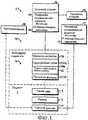
Фиг.1 представляет собой схематическую блок-схему лечения закрытия тканей и системы, выполненной по данному изобретению;Figure 1 is a schematic block diagram of a treatment for tissue closure and the system of this invention;
фиг.2 иллюстрирует в аксонометрии разделение разреза ткани с установленной трубкой глубокого дренажа;figure 2 illustrates in a perspective view the separation of the incision of the tissue with the installed deep drainage tube;
фиг.3 представляет собой вид в аксонометрии разреза ткани, показывающий рассеченную ткань с наложенным швом у кожи;Fig. 3 is a perspective view of a tissue incision showing a dissected tissue sutured to the skin;
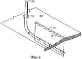
фиг.4. представляет собой вид в аксонометрии разреза ткани, показывающий рассеченную ткань с наложенным швом у глубокого дермального слоя под поверхностью кожи;figure 4. is a perspective view of a tissue incision showing a dissected tissue with a suture at the deep dermal layer under the skin surface;
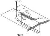
фиг.5 представляет собой вид в аксонометрии разреза ткани, показывающий первичный компонент переноса жидкости из вискозной полосы (КПЖ.1) и нижнюю салфетку, помещенную на линию шва;Fig. 5 is a perspective view of a tissue incision showing the primary component of fluid transfer from a viscose strip (CSF 1) and a lower wipe placed on a seam line;
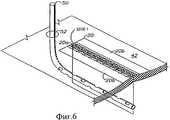
фиг.6 представляет собой вид в аксонометрии разреза ткани, показывающий КПЖ.1 и нижнюю салфетку на месте линии шва;6 is a perspective view of a tissue incision showing CPG. 1 and the lower wipe in place of the seam line;
фиг.7 представляет собой вид в аксонометрии разреза ткани, показывающий вторичный компонент переноса жидкости (КПЖ.2), установленный на место.Fig. 7 is a perspective view of a tissue incision showing a secondary fluid transfer component (CSF 2) in place.
фиг.8 представляет собой вид в аксонометрии разреза ткани, показывающий верхнюю салфетку на месте;Fig. 8 is a perspective view of a tissue incision showing the upper tissue in place;
фиг.9 представляет собой вид в аксонометрии разреза ткани, показывающий соединительный компонент переноса жидкости (КПЖ.3) на месте, предназначенный для присоединения данной системы к источнику отрицательного давления;Fig.9 is a perspective view of a tissue incision showing the fluid transfer connecting component (CSF. 3) in place, designed to connect this system to a negative pressure source;
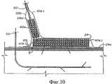
фиг.10 представляет собой разрез по линии 10-10 на фиг.9, частично иллюстрирующий КПЖ.3;figure 10 is a section along the line 10-10 in figure 9, partially illustrating CSF. 3;
фиг.11а представляет собой вид в аксонометрии разреза ткани, показывающий снятый КПЖ.3 и верхнюю салфетку с надрезами для вентиляции;11a is a perspective view of a tissue incision showing a removed CPG. 3 and an upper tissue with incisions for ventilation;
фиг.11b представляет собой вид в аксонометрии разреза ткани, показывающий средство воздействия на пациента, снятое по линии перфорации в нижней салфетке, и линию прорези в верхней салфетке;11b is a perspective view of a tissue incision showing a means of influencing the patient, taken along the perforation line in the lower napkin, and a cut line in the upper napkin;
фиг.11с представляет собой вид в аксонометрии средства воздействия на пациента, предназначенное для поставки в упаковке, наложения на пациента и присоединения к источнику отрицательного давления;Fig. 11c is a perspective view of a means of influencing a patient, intended for delivery in a package, applied to a patient and connected to a source of negative pressure;
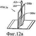
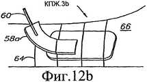
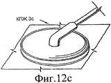
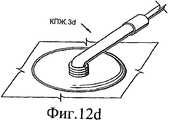
фиг.12а-d показывают, соответственно, другой вариант выполнения коленчатого соединительного устройства КПЖ.3а-d;figa-d show, respectively, another embodiment of a cranked connecting device KPZH.3a-d;
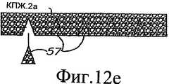
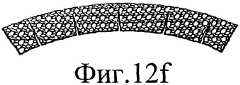
фиг.12е, f показывают видоизмененный КПЖ.2а с удаленными клиньями для содействия сочленению, например в изгибании сустава пациента;12e, f show a modified CPG. 2a with wedges removed to facilitate articulation, for example in flexing a patient's joint;
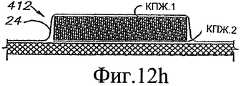
фиг.12g, h показывают другой вариант узла наружного средства воздействия на пациента;Fig. 12g, h show another embodiment of an external means for treating a patient;
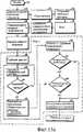
фиг.13а-с изображают блок-схемы, иллюстрирующие способ лечения закрытия тканей по данному изобретению;figa-c depict flowcharts illustrating a method of treating tissue closure according to this invention;
фиг.14 изображает блок-схему автоматизированной системы лечения закрытия тканей, содержащей другой вариант выполнения данного изобретения;FIG. 14 is a block diagram of an automated tissue closure treatment system comprising another embodiment of the present invention; FIG.
фиг.15 представляет собой вид в разрезе другого варианта выполнения автоматизированной системы лечения закрытия тканей;Fig. 15 is a sectional view of another embodiment of an automated tissue closure treatment system;
фиг.16 представляет собой частичную блок-схему другого варианта выполнения автоматизированного способа лечения закрытия тканей;Fig is a partial block diagram of another embodiment of an automated method for the treatment of tissue closure;
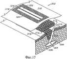
фиг.17 представляет собой фрагментарный вид в аксонометрии системы лечения закрытия тканей в другом варианте выполнения данного изобретения вместе с эксплуатационной повторно закрываемой панелью;FIG. 17 is a fragmentary perspective view of a tissue closure treatment system in another embodiment of the present invention, together with an operational reclosable panel; FIG.
фиг.18 представляет собой вид в аксонометрии эксплуатационной повторно закрываемой панели;FIG. 18 is a perspective view of an operational re-closable panel; FIG.
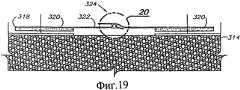
фиг.19 представляет собой разрез системы лечения закрытия тканей по линии 19-19 на фиг.18;Fig. 19 is a sectional view of a tissue closure treatment system along line 19-19 of Fig. 18;
фиг.20 представляет собой увеличенный вид в разрезе системы закрытия тканей, в частности иллюстрирует ее уплотнительную повторно закрываемую полосу;FIG. 20 is an enlarged sectional view of a tissue closure system, in particular illustrates its sealing re-closable strip; FIG.
фиг.21 представляет собой вид в аксонометрии системы закрытия тканей, показывающий уплотнительную полосу в открытом виде;Fig is a perspective view of a tissue closure system, showing the sealing strip in the open;
фиг.22 представляет собой вид в аксонометрии системы закрытия тканей, показывающий уплотнительную полосу в открытом виде и снятый вспененный элемент;FIG. 22 is a perspective view of a tissue closure system showing an open sealing strip and a removed foam member; FIG.
фиг.23 представляет собой разрез наружного перевязочного материала, который содержит другой вариант выполнения данного изобретения;23 is a sectional view of an external dressing that comprises another embodiment of the present invention;
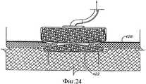
фиг.24 представляет собой разрез другого варианта выполнения системы закрытия тканей с внутренним и наружным вспененными элементами;24 is a sectional view of another embodiment of a tissue closure system with internal and external foam elements;
фиг.25 представляет собой разрез системы, показанной на фиг.24, иллюстрирующий постепенное заживление ткани в ране;Fig.25 is a section of the system shown in Fig.24, illustrating the gradual healing of tissue in the wound;
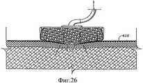
фиг.26 представляет собой разрез системы, показанной на фиг.25, иллюстрирующий повторную эпителизацию раны;Fig.26 is a section of the system shown in Fig.25, illustrating re-epithelialization of the wound;
фиг.27 представляет собой разрез вспененного элемента, частично заключенного в оболочку из вискозы;Fig is a section of a foamed element, partially enclosed in a shell of viscose;
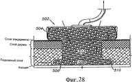
фиг.28 представляет собой разрез другого варианта выполнения системы закрытия тканей с наружным и внутренним вспененными элементами в сборке;FIG. 28 is a sectional view of another embodiment of a tissue closure system with external and internal foam elements in an assembly; FIG.
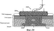
фиг.29 представляет собой такой же разрез, но показанный с частичным стягиванием под воздействием давления окружающей атмосферы;Fig.29 is the same section, but shown with partial contraction under the influence of the pressure of the surrounding atmosphere;
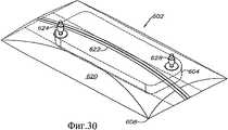
фиг.30 представляет собой вид в аксонометрии перевязочного материала другой конструкции с уплотнительной повторно закрываемой полосой и отверстиями для доступа жидкости;FIG. 30 is a perspective view of a dressing of a different design with a sealing re-closable strip and fluid access openings;
фиг.31 представляет собой вид в аксонометрии нижней стороны перевязочного материала, показывающий удаляемую среднюю защитную полосу;Fig is a perspective view of the lower side of the dressing, showing the removable middle protective strip;
фиг.32 представляет собой вид в аксонометрии перевязочного материала, показывающий удаляемые боковые защитные полосы;32 is a perspective view of the dressing showing removable side protective strips;
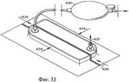
фиг.33 представляет собой вид в аксонометрии перевязочного материала, показанного с грушевидным сжимаемым эвакуатором, прикрепленным к отверстию для жидкости;Fig. 33 is a perspective view of the dressing shown with a pear-shaped compressible tow truck attached to a fluid hole;
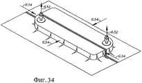
фиг.34 представляет собой вид в аксонометрии перевязочного материала, показанного частично стянутым под воздействием атмосферного давления;Fig. 34 is a perspective view of a dressing shown partially constricted by atmospheric pressure;
фиг.35 представляет собой вид в аксонометрии перевязочного материала, показанного с открытой уплотнительной полосой;Fig. 35 is a perspective view of the dressing shown with an open sealing strip;
фиг.36 представляет собой вид в аксонометрии перевязочного материала, показанного со снятым вспененным элементом;Fig. 36 is a perspective view of the dressing shown with the foam element removed;
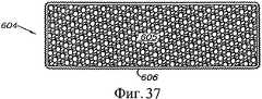
фиг.37 представляет собой разрез вспененного элемента, полностью заключенного в оболочку из вискозы;Fig. 37 is a sectional view of a foamed element completely enclosed in a viscose sheath;
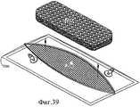
фиг.38 представляет собой вид в аксонометрии другого варианта выполнения перевязочного материала с отдельной прокладкой и вспененным элементом;Fig. 38 is a perspective view of another embodiment of a dressing with a separate pad and a foam member;
фиг.39 представляет собой вид в аксонометрии перевязочного материала, показанного со снятым вспененным элементом;Fig. 39 is a perspective view of the dressing shown with the foam element removed;
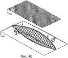
фиг.40 представляет собой вид в аксонометрии перевязочного материала, показанного со снятой прокладкой;40 is a perspective view of the dressing shown with the pad removed;
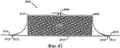
фиг.41 представляет собой разрез другого варианта выполнения перевязочного материала с оболочковой нижней панелью, содержащей впитывающий жидкость материал;Fig. 41 is a sectional view of another embodiment of a dressing with a sheath bottom panel containing a liquid absorbent material;
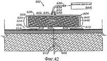
фиг.42 представляет собой разрез другого варианта выполнения системы перевязочного материала с элементом переноса с покрытой вспененной центральной частью;Fig. 42 is a sectional view of another embodiment of a dressing system with a transfer member with a coated foam core;
фиг.43 представляет собой такой же разрез, показывающий сжатый перевязочный материал под воздействием давления;Fig is a similar section showing a compressed dressing material under pressure;
фиг.44 представляет собой вид сверху варианта, показанного на фиг.42;Fig.44 is a top view of the variant shown in Fig.42;
фиг.45 представляет собой разрез варианта, показанного на фиг.42, показывающий конфигурацию перевязочного материала до использования на пациенте и взятый по линии 45-45 на фиг.44;Fig. 45 is a sectional view of the embodiment shown in Fig. 42, showing the configuration of the dressing before use on the patient and taken along line 45-45 in Fig. 44;
фиг.46 представляет собой вид сверху аппликации, содержащей множество перевязочных слоев, покрывающих удлиненное рассечение ткани, например, хирургический разрез;Fig. 46 is a top view of an application containing a plurality of dressing layers covering an elongated tissue incision, for example, a surgical incision;
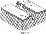
фиг.47 представляет собой вид в аксонометрии раны с дренажными полосами, установленными в подготовленную для закрытия рану;Fig. 47 is a perspective view of a wound with drainage strips installed in a wound prepared for closure;
фиг.48 представляет собой разрез перевязочного материала, содержащего другой вариант выполнения данного изобретения, с верхним и нижним слоями из вискозы;Fig. 48 is a sectional view of a dressing material containing another embodiment of the present invention, with upper and lower layers of viscose;
фиг.49 представляет собой разрез материала, показанного на фиг.48, в сжатом состоянии;Fig. 49 is a sectional view of the material shown in Fig. 48 in a compressed state;
фиг.50 представляет собой разрез перевязочного материала, содержащего другой вариант выполнения данного изобретения, с покрытием из вискозы, охватывающим сетчатую вспененную центральную часть;Fig. 50 is a sectional view of a dressing material comprising another embodiment of the present invention, with a viscose coating covering the mesh foam core;
фиг.51 представляет собой разрез материала, показанного на фиг.50, в сжатом состоянии;Fig. 51 is a sectional view of the material shown in Fig. 50 in a compressed state;
фиг.52 представляет собой разрез перевязочного материала, содержащего другой вариант выполнения данного изобретения, с датчиком, подключенным к контроллеру;Fig. 52 is a sectional view of a dressing material containing another embodiment of the present invention, with a sensor connected to the controller;
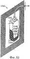
фиг.53 представляет собой вид в аксонометрии экспериментальной модели перевязочного материала для наблюдения через него за жидкостью;Fig. 53 is a perspective view of an experimental model of dressing for observing fluid through it;
фиг.54 представляет собой график, показывающий зависимость смачиваемой зоны поверхности сетчатой вспененной центральной части от объема жидкости для различных условий;Fig. 54 is a graph showing the dependence of the wetted area of the surface of the mesh foam central portion on the volume of liquid for various conditions;
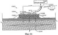
фиг.55 представляет собой разрез гемостата, содержащего другой вариант выполнения данного изобретения.55 is a sectional view of a hemostat containing another embodiment of the present invention.
Предпочтительные варианты выполнения данного изобретенияPreferred Embodiments of the Invention
I. Введение и окружающие условияI. Introduction and environmental conditions
В соответствии с требованиями в данном документе приведено описание детальных вариантов выполнения данного изобретения, однако следует понимать, что рассматриваемые варианты выполнения приведены только в качестве примера, которые могут быть выполнены в любых формах. Следовательно, особые структурные и функциональные детали, описанные в данном документе, не следует трактовать как ограничивающие, а следует рассматривать в качестве основополагающего принципа для формулы изобретения, а также в качестве репрезентативной базы для объяснения специалистам данной области техники различного использования данного изобретения по существу в любой соответствующей конкретной структуре.In accordance with the requirements in this document is a description of the detailed embodiments of the present invention, however, it should be understood that the considered embodiments are given only as an example, which can be performed in any form. Therefore, the special structural and functional details described in this document should not be construed as limiting, but should be considered as a fundamental principle for the claims, as well as a representative basis for explaining to specialists in this field of technology the various uses of this invention in essentially any corresponding to a specific structure.
II. Система 2 закрытия тканиII.
Рассмотрим более подробно чертежи, на которых ссылочной позицией 2 в целом обозначен вариант выполнения предложенной системы закрытия ткани.Let us consider in more detail the drawings, in which reference numeral 2 generally designates an embodiment of the proposed tissue closure system.
Как показано на фиг.1, система 2 приспособлена для использования на пациенте 4, имеющем разрез или рану 6, которая может быть закрыта линией 8 шва, содержащей нити 10 для сшивания раны, скобки или другие подходящие медицинские крепежные средства.As shown in FIG. 1,
Средство 12 воздействия на пациента содержит, как вариант, глубокий дренаж 14, присоединенный к источнику 15 отрицательного давления для глубокого дренажа, который связан с резервуаром 17 для глубокого дренажа и наружным средством 16 воздействия на пациента, содержащим первичный компонент КПЖ.1 переноса жидкости, содержащий полосу из вискозы или другого подходящего пористого материала, нижнюю салфетку 20, по существу, покрывающую КПЖ.1 и имеющую прорезь 20а, вторичный компонент КПЖ.2, содержащий гидрофобную губку и верхнюю салфетку 24.The patient exposure means 12 comprises, optionally, a
Подсистема 26 регулирования жидкости содержит источник 15 отрицательного давления для глубокого дренажа и источник 28 отрицательного давления для поверхностного дренажа, которые могут быть объединены для областей применения, в которых предпочтителен общий источник отрицательного давления и собирающий приемник. Источники 15, 28 могут работать либо с ручным приводом, либо с механическим. Примеры обоих типов являются хорошо известными в области медицины. Например, ручной портативный вакуум-источник (MOPVS) известен из патента США №3115138, который включен в данное описание посредством ссылки. MOPVS выпускается компанией Zimmer, Inc. of Dover, Огайо под товарным знаком HEMOVAC®. На небольших ранах для более короткой продолжительности работы или многократного применения могут использоваться приводы грушевидного типа, такие как показаны в патенте США №4828546 (включенным в данный документ посредством ссылки), и выпускаемые компанией Surgidyne, Inc. of Eden Praire, Миннесота. Кроме того, создание отрицательного давления посредством механического привода может быть обеспечено вакуум-оборудованием, способствующим закрытию ран, выпускаемым под товарным знаком THE VAC® компанией Kinetic Concepts, Inc. of San Antonio, Техас. Дополнительно, многочисленные медицинские учреждения, в частности больницы и клиники, оборудованы системами разрежения, источник разрежения которых расположен в настенных выходных средствах.The fluid control subsystem 26 comprises a
Резервуар 30 конечной емкости проточно присоединен к источнику 28 отрицательного давления и приспособлен для выпуска в приемник 32 для отходов. С резервуаром 30 связан отсечной клапан 34, который автоматически отключает дренаж при заполнении резервуара 30 до определенного объема.The
К глубокому дренажу 14, как вариант, может быть присоединена подсистема 36 аутотрансфузии для переливания пациенту 4 его собственной крови. В патенте США №5785700, который включен в данный документ посредством ссылки, приведено описание подобной системы аутотрансфузии с переносным съемным вакуум-источником, которая выпускается компанией Zimmer, Inc.Alternatively, a deep transfusion subsystem 36 may be attached to the
Фиг.2 показывает разрез 6, образующий первый и второй разделенные участки 38а,b ткани с краями 40а,b разреза. Разрез 6 проходит от кожи 42 и раскрывается около нее через глубокий слой 44 дермы и подкожный слой 46 приблизительно до фасции 48. В нижнюю часть разреза 6 помещена трубка 50 для глубокого дренажа, которая проходит через кожу 42 в отверстии 52.Figure 2 shows a
Фиг.3 показывает края 40а,b разреза, скрепленные вместе нитями 54, образующими линию 56 шва у поверхности 42 кожи. В качестве альтернативы нитям 54 могут быть использованы другие различные медицинские крепежные средства, например скобки. Фиг.4 показывает нити 55, помещенные в глубокий слой 44 дермы под поверхность 42 кожи.Figure 3 shows the edges of the section 40a, b fastened together with
Фиг.5 иллюстрирует применение КПЖ.1 на верхней части линии 8 шва. КПЖ.1 предпочтительно содержит подходящий пористый впитывающий материал, например вискозу, которая хорошо подходит для впитывания жидкости, выделяющейся вдоль линии 8 шва. Вискоза также имеет тенденцию к относительно быстрому высыханию и, таким образом, эффективно переносит через себя жидкость. Нижняя салфетка 20 помещена поверх КПЖ.1 непосредственно выше линии 8 шва. Прорезь 20а салфетки расположена в целом по центру вдоль центральной линии КПЖ.1 непосредственно над линией 8 шва. КПЖ.1 и нижняя салфетка 20 могут быть предварительно объединены в рулон или какую-либо другую подходящую конфигурацию, приспособленную для облегчения размещения на линии 8 шва на любую необходимую длину. Фиг.6 показывает КПЖ.1 и нижнюю салфетку 20, размещенные на месте.Figure 5 illustrates the use of CSF. 1 on the upper part of the
На фиг.7 показан размещенный вторичный компонент КПЖ.2 переноса жидкости. Он предпочтительно содержит подходящий гидрофобный вспененный материал, например полиуретан-эфир (ПУЭ), который содержит сетчатый, наподобие решетки (вспененный), материал, способный сжиматься под действием силы, обусловленной вакуумом (создаваемой разрежением), с целью оказания положительной компрессии, по типу «обертывания в термоусадочный материал», на поверхность кожи, а также поддержания каналов, обеспечивающих прохождение жидкости. Как показано, площадь его основания несколько меньше площади основания нижней салфеткой 20, что способствует образованию кромки 20b нижней салфетки. Впитывающий слой КПЖ.1 может, как вариант, иметь размер, равный или почти равный площади основания КПЖ.2. Такая конфигурация способствует ее изготовлению как отдельной предварительно собранной мягкой прокладки, которая может использоваться простым удалением освобождающего защитного слоя с покрытой клеем нижней салфетки. Такая конфигурация также способствует облегчению полного удаления и замены центральной части приспособления без удаления уже приклеенной салфетки к коже, если удаление и замена являются более желательным лечебным вариантом, чем поэтапное удаление или пролонгация одной аппликации.In Fig.7 shows the placed secondary component of the CPG.2 fluid transfer. It preferably contains a suitable hydrophobic foamed material, for example polyurethane ether (PUE), which contains a mesh like a lattice (foamed), a material capable of being compressed by the force caused by vacuum (created by vacuum), to provide positive compression, of the type " shrink wraps "on the surface of the skin, as well as maintaining channels that allow fluid to pass through. As shown, its base area is slightly smaller than the base area of the lower wipe 20, which contributes to the formation of the
Фиг.8 показывает верхнюю салфетку 24, выполненную поверх КПЖ.2 и нижней салфетки 20, с кромкой 24а, проходящей за пределами кромки 22b нижней салфетки и входящей в контакт с поверхностью 42 кожи пациента (с дермой). Фиг.9 и 10 показывают соединитель-накладку 58, размещенный на КПЖ.2 и содержащий центральную часть 58а из гидрофобного вспененного материала (ПУЭ), помещенного между слоями 58b салфеток. Вакуумная дренажная трубка 60, входной конец 60а которой встроен во вспененную центральную часть 56а, проходит между слоями 58b салфеток к выходному концу 60b, присоединенному к источнику 28 отрицательного давления для поверхностного дренажа.Fig. 8 shows an
Фиг.11а показывает КПЖ.3, снятый, например срезанием части верхней салфетки 24 для создания в ней отверстия 54. В дополнение, верхняя салфетка 24 может быть прорезана в местах 55 для дополнительной вентиляции КПЖ.2. Дренирование КПЖ.2 под воздействием отрицательного давления и дополнительное осушение его посредством циркуляции воздуха (фиг.11а) может обеспечить значительные преимущества по заживлению посредством снижения роста различных микробов, требующих влажной среды в КПЖ.2. Таким образом, имеющиеся подобные микробы и различные токсины могут быть обезвожены, нейтрализованы и не допущены иным способом к повторному внедрению в пациента. Кроме того, контроль над микробами может быть осуществлен введением антисептиков в различные компоненты средства 12 и их промыванием, включая салфетки 20, 24, КПЖ.1, КПЖ.2, КПЖ.3.11 a shows KPZH.3, taken, for example, by cutting off part of the
Фиг.11b показывает средство 12 воздействия, удаленное по линиям 56 перфорации нижней салфетки и линиям 59 прорези в верхней салфетке 24. Следует понимать, что по существу, все средство 12, за исключением кромок 20b, 24а нижней и верхней салфетки, может быть удалено, чтобы обеспечить доступ к линии 8 шва и коже 42 для визуального осмотра, оценки состояния, очистки, снятия швов, смены повязки (например, предварительно упакованным средством 12а воздействия, как показано на фиг.11с), с учетом дополнительных вариантов лечения, и т.д. Например, верхняя салфетка 24 может быть прорезана по периметру или основанию КПЖ.2 для его удаления. Предпочтительно, КПЖ.2 может быть легко высвобожден из нижней салфетки 20 и КПЖ.1 и, соответственно, захвачен и поднят вверх для облегчения прохождения скальпеля через верхнюю салфетку 24 в разрез между нижней стороной КПЖ.2 и нижней салфеткой 20. Затем КПЖ.1 может быть, как вариант, удален посредством разрыва нижней салфетки 20 по ее линиям 56 разрыва и снят, как показано на фиг.11b.11b shows the impact means 12 removed along the perforation lines 56 of the lower cloth and the cut lines 59 of the
Фиг.11с показывает предварительно упакованное средство 12 воздействия на пациента, предназначенное для первичного использования или «замены перевязки». Как вариант, вискозная полоса КПЖ.1 может иметь форму, одинаковую с формой или «отпечатком» вспененной губки КПЖ.2, с исключением, таким образом, нижней салфетки 20. Средство 12 может быть стерильно упаковано для облегчения непосредственного его размещения на линии 8 шва. Как вариант, компоненты средства воздействия на пациента могут быть заранее упакованы отдельно или подходящими группами, содержащими сборочные компоненты полного средства 12 воздействия на пациента. Например, соответственно, сборочные компоненты нижней салфетки/КПЖ.1 и верхней салфетки /КПЖ.2 могут быть заранее упакованы отдельно. Компоненты средства воздействия на пациента с различными размерами и конфигурациями могут быть заранее упакованы для применения в соответствии с состоянием конкретного пациента. Предпочтительно некоторые размеры и конфигурации должны быть относительно «универсальными» с возможностью использования для конкретных медицинских операций, например полной замены сустава (ПЗС), что обусловливает возможность упрощения предлагаемого средства воздействия. Как вариант, отдельные компоненты могут быть собраны с различными размерами и конфигурациями для применения в соответствии с определенным заказом.11c shows pre-packaged patient exposure means 12 for primary use or “dressing replacement”. Alternatively, the viscose strip KPZH.1 can have a shape identical to the shape or “imprint” of the foam sponge KPZH.2, with the exception, therefore, of the
Фиг.12а-d показывают другие соединительные компоненты КПЖ.3а-d переноса жидкости, предназначенные для присоединения КПЖ.2 к источнику 28 отрицательного давления для поверхностного дренажа. КПЖ.3а (фиг.12а) представляет собой соединитель-накладку с конструкцией, аналогичной конструкции КПЖ.3, и приспособленный для размещения в любом месте на верхней салфетке 24. КПЖ.3а выполнен с соединителем 62 типа замка Люэра. КПЖ.3b (фиг.12b) содержит полосу из гидрофобного вспененного материала (ПУЭ), частично покрытого верхней салфеткой 64, которая может быть выполнена в виде оболочки вокруг руки или ноги 66 пациента. КПЖ.3с (фиг.12с) представляет собой соединитель коленчатого типа. КПЖ.3а (фиг.12а) представляет собой коленчатый соединитель гофрированного типа, который приспособлен для размещения отвода дренажной вакуум-трубки 60.Figa-d show other connecting components KPZH.3a-d fluid transfer, designed to connect KPZH.2 to the
Фиг.12e, f показывают другую конструкцию КПЖ.2а с множеством выполненных в ней удаляемых клиньев 57 и приспособленную для размещения сочленения, например изгиба сустава. Таким образом, гибкость КПЖ.2а может быть значительно увеличена для обеспечения комфорта, подвижности и гибкости пациенту. Подобные клинья могут проходить в поперечном и/или продольном направлении относительно КПЖ.2а. КПЖ.2а действует одинаковым образом, независимо от того, удалены клинья 57 или находятся на месте.12e, f show another construction of the CPG. 2a with a plurality of
Фиг.12g показывает модифицированное средство 312 воздействия на пациента с нижней салфеткой 20, помещенной под КПЖ.1. Такая конфигурация позволяет выполнять удаление КПЖ.1 без нарушения нижней салфетки 20. Фиг.12h показывает другое модифицированное средство 412 воздействия на пациента, в котором конфигурация КПЖ.1 аналогична конфигурации или площади основания КПЖ.2, что обусловливает возможность их совместного изготовления и соединения. В этой конфигурации нижняя салфетка 20 может отсутствовать.12g shows a modified
III. Способ леченияIII. Method of treatment
Фиг.13а-с показывают блок-схемы, иллюстрирующие способ реализации данного изобретения. От начального этапа 70 данный способ переходит к этапу 72 диагностики пациента и анализу, а на этапе 74 - к плану лечения. На этапе 76, при необходимости, устанавливают глубокий дренаж 14 и на этапе 78 на разрез накладывают швы. На этапе 80 накладывают поверхностные компоненты 12 средства воздействия и на этапе 82 их подсоединяют к внешним компонентам (т.е. источникам 15, 28 отрицательного давления). На этапе 84 задают емкость резервуара-сборника, исходя из таких факторов, как характер раны/разреза, кровотечения и т.д.13a-c show flowcharts illustrating an embodiment of the present invention. From the
Фаза 1
На этапе 86 происходит глубокий дренаж, а на этапе 88 - активный поверхностный дренаж, оба проводятся под воздействием источников 15, 28 отрицательного давления. Источник 28 отрицательного давления вызывает частичное сжатие вспененного КПЖ.2 из ПУЭ, при этом, соответственно, опускается вниз верхняя салфетка 24, которая оказывает положительное сжимающее усилие на закрытую рану или разрез 6. Подобное усилие в закрытой среде средства 12 эффективно ограничивается окружающим воздухом. Это регулирующее ограничивающее свойство защищает пациента от чрезмерного усилия, оказываемого средством 12. Неизменное давление, вплоть до одной атмосферы, приложенное к закрытой ране или разрезу 6, действует аналогично шине или гипсовому слепку, препятствуя отеканию и способствуя заживлению.At
Если на этапе 90 определяется условие «резервуар наполнен», то выполняется переход к этапу 92 прерывания создания отрицательного давления для поверхностного дренажа, после которого содержимое резервуара проверяют и на этапе 94 удаляют. Если на этапе 96 принятия решения при визуальном осмотре определяется поверхностное кровотечение, то данный способ переходит к этапу 98 «прекращения активного поверхностного дренажа». Если на этапе 100 принятия решения линия шва подвергается активному дренажу, то способ возвращается к этапу 88 активного поверхностного дренажа и продолжает его, в противном случае поверхностный дренаж прерывается на этапе 98, т.е. когда рана/разрез не кровоточит и не выделяет жидкости.If the condition "the tank is full" is determined at
Фаза 1, в целом, характеризуется глубоким дренажем (интерактивным или пассивным), а активный поверхностный дренаж проводится под воздействием всасывания, выполняемого вручную или приводным механизмом. Нормальная длительность дренажа составляет приблизительно от двух до трех дней, во время которого послеоперационная или посттравматическая отечность обычно достигает своего максимума и начинает уменьшаться.
Фаза 2
Фиг.13b иллюстрирует Фазу 2, которая начинается этапом 102 принятия решения - «Многоэтапное удаление компонентов?». Положительное решение приводит к этапу 103 независимого выключения и удаления компонентов, включая прекращения активного всасывания на этапе 104, которое обусловливает преобразование внутреннего давления гидрофобного вспененного материала из ПУЭ (КПЖ.2) из отрицательного в положительное и допускает на этапе 106 восстановление формы сжатого КПЖ.2, потенциально увеличивая комбинированное поверхностное давление от значения окружающего давления до положительного. Предпочтительно этот переход от декомпрессии происходит без приложения к поверхности чрезмерного давления. Во время фазы 1 отрицательное давление (т.е. всасывание/вакуум) стремится сжать КПЖ.2 и, соответственно сжать верхнюю салфетку 24, добавляя компрессию, оказываемую КПЖ.2. Когда прерывается подача отрицательного давления, вручную или автоматически, КПЖ.2 восстанавливает форму, преодолевая противодействие верхней салфетки 24, и с давлением, равным реакции и противоположно направленным, прижимается к коже 42, в частности вдоль линии шва 8. Таким образом, КПЖ.2 может автоматически изменять давление от окружающего до положительного просто прерыванием приложения вакуум-источника.13b illustrates
Положительное давление, оказываемое на кожу 42, продолжает сжимать и стабилизировать ткань вдоль линии 8 шва (этап 108), обеспечивая уменьшение отечности, и взаимодействует с работой КПЖ.1 и КПЖ.2 для продолжения дренажа посредством испарения у линии 8 шва на этапе 110. Отрицательное решение, принятое блоком принятия решения на этапе 102, приводит к удалению средства воздействия на этапе 112 и, до окончания лечения, на этапе 113 выполняется осмотр и лечение, а на этапе 114 выполняется замена средства воздействия, которая может включать частичную или полную замену средства 12. Данный способ затем переходит к фазе 3.The positive pressure exerted on the
Фаза 3Phase 3
Фиг.13 с иллюстрирует способ лечения, в котором на этапе 118 прекращен глубокий дренаж и удалена трубка(и). На этапах 120, 122, соответственно удаляют верхнюю салфетку 24 и КПЖ.2. На этапе 124 нижняя салфетка 20 и КПЖ.1 предпочтительно выполнены так, чтобы позволить провести осмотр через них линии 8 шва. Когда линия 8 шва будет достаточно закрыта, на этапе 126 удаляют нижнюю салфетку 20 и КПЖ.1 и на этапе 128 заканчивают лечение. Как вариант и если это определяется состоянием пациента, в фазе 3 может быть выполнена полная или частичная замена средства 12 воздействия и продолжено лечение.13 c illustrates a treatment method in which, at step 118, deep drainage is stopped and the tube (s) is removed. At
IV. Другой вариант выполнения системы 202 закрытия тканиIV. Another embodiment of a
Фиг.14 схематически показывает систему 202 закрытия ткани, включающую другой вариант выполнения данного изобретения, содержащий микропроцессор или контроллер 204, который может быть подключен к одному или более датчикам 206, соединенным со средством 12 воздействия для выявления различных состояний, связанных с пациентом 4. Микропроцессор 204 может быть запрограммирован для обеспечения работы соленоида 208, соединенного с клапаном 210, связанным с резервуаром 30, и управляющего потоком жидкости, создаваемым источником 228 отрицательного давления, посредством его подсоединения к средству 12.14 schematically shows a
Фиг.15 показывает систему 202 закрытия ткани с микропроцессором 204, присоединенным к множеству датчиков 206а, b, с, каждый из которых соответственно связан с компонентом управления потоком, например, клапаном 210а, b, с. Каждый компонент 210а, b, с управления потоком связан с соответствующим источником 228а, b, с отрицательного давления, который в свою очередь управляет жидкостью, выпускаемой соответственно из контейнеров или резервуаров 212a, b, c. Например, средство 12 воздействия может содержать наружное средство 16 воздействия на пациента, как описано выше, и пару трубок 50a, b глубокого дренажа. Средство 12 содержит, как вариант, подающий компонент 214, который может содержать один или более резервуаров для жидкости, насосы (с ручным или механическим приводом) и связанные средства управления, которые могут присоединяться к микропроцессору 204 для управления системой. Подающий компонент 214, как вариант, выбирает одну или более трубок 50, 60 для подачи жидкости к пациенту через трубки 50 глубокого дренажа или через наружное средство 16. Подобные жидкости могут содержать, например, антибиотики и средства для эстетики, орошающие реагенты, фактор роста и любую другую жидкость, полезную для содействия лечению, подавления инфекции и улучшения комфортного состояния пациента.FIG. 15 shows a
Методика лечения с помощью другого варианта выполнения системы 202 закрытия ткани показана на фиг.16 и в целом включает предварительное лечение 230 и процедуры фазы 1. От этапа «Начало» способ переходит к этапу 234 диагностики/оценки, этапу 236 плана лечения, этапу 238 установки глубокого дренажа, этапу 240 наложения шва, этапу 246 наложения компонента наружного средства воздействия, этапу 244 программирования микропроцессора и этапу 246 подсоединения компонентов накладки, например подсоединения системы труб. Фаза 1 начинается с этапа 248 глубокого дренажа, этапа 250 активного всасывания средством взаимодействия и этапа 252 блока принятия решения «Активный дренаж линии шва?». При принятии решения об активном дренаже линии шва способ возвращается обратно к этапу 250, в противном случае (отрицательное решение на этапе 253) он переходит к фазе 2.The treatment method using another embodiment of the
V. ПрименениеV. Application
Без ограничения общего характера полезных применений систем 2 и 202 закрытия ткани по данному изобретению, нижеприведенное частичное перечисление представляет возможные состояния пациента и процедуры, которые могут определить применение данного изобретения.Without limiting the general nature of the beneficial uses of
- Поверх рассечений для закрытия ткани, таких как хирургические разрезы.- On top of incisions to close tissue, such as surgical incisions.
- Поверх суставов, где разрезы подвергаются перемещению и растяжению, такие как резекция сустава, реконструктивные и косметические операции, исправление кожных лоскутов и шрамов, операции по полной замене сустава (ПЗС), т.е. бедра, колена, локтя, плеча и стопы.- On top of the joints, where the incisions are moved and stretched, such as joint resection, reconstructive and cosmetic surgeries, correction of skin flaps and scars, joint replacement surgery (CCD), i.e. hips, knee, elbow, shoulder and foot.
- Любая рана в области толстой или зыбкой подкожной ткани, в которой шинирование кожи и подкожной ткани может уменьшить раскрыв глубоких швов.- Any wound in the area of thick or unsteady subcutaneous tissue in which splinting of the skin and subcutaneous tissue can reduce the opening of deep sutures.
- Раны на протяжении реконструктивных операций, в которых создаются неровные полости, включающих резекцию опухолей, имплантантов, кости и других тканей. Изменения длины и геометрии конечностей, а также изменения размера, положения и очертания костей и других глубоких структур.- Wounds during reconstructive operations in which uneven cavities are created, including resection of tumors, implants, bone and other tissues. Changes in the length and geometry of the limbs, as well as changes in the size, position and shape of bones and other deep structures.
- Раны, в которых важным является удаление омертвевшей области и предотвращение ее образования.- Wounds in which it is important to remove the dead area and prevent its formation.
- Лечение гематом и серозных образований.- Treatment of hematomas and serous formations.
- Ампутация культей.- Amputation of stumps.
- Брюшные, грудные, боковые и другие раны, в которых шинирование раны может содействовать закрытию и мобилизации пациента во время послеоперационного периода.- Abdominal, thoracic, lateral and other wounds in which splinting of the wound can contribute to the closure and mobilization of the patient during the postoperative period.
- Раны в участках тонкой или чувствительной кожи, в которых многократное удаление или замена ленты или других клейких средств может вызывать боль, раздражение или образование волдырей на коже около раны. А также в тех случаях, когда замена повязки может вызвать сдвиг или смещение ткани, ухудшающее первичное заживление раны.- Wounds in areas of thin or sensitive skin in which repeated removal or replacement of tape or other adhesive may cause pain, irritation or blistering of the skin near the wound. And also in those cases when replacing the dressing can cause a shift or displacement of the tissue, worsening the initial healing of the wound.
- Раны в случаях, когда пациент выражает желание принять ванну до недостаточного заживления раны, для того чтобы не внести грязь с водой из ванны или душа.- Wounds in cases where the patient expresses a desire to take a bath before the wound is not sufficiently healed, so as not to introduce dirt and water from the bath or shower.
- Раны, подвергающиеся загрязнению фекалиями, мочой и другими жидкостями тела.- Wounds contaminated with feces, urine and other body fluids.
- Пациенты отделений педиатрии, гериатрии, психиатрии и неврологии, а также пациенты других отделений, которые могут нарушать перевязки и раны.- Patients of the departments of pediatrics, geriatrics, psychiatry and neurology, as well as patients of other departments that can disrupt dressings and wounds.
- Пациенты с многочисленными консультантами и кураторами, когда многократное обследование раны может ухудшить заживление.- Patients with numerous consultants and curators, when repeated examination of the wound can worsen healing.
- Глубокое закрытие и наложение поверхностных швов и скобок.- Deep closure and superficial seams and brackets.
- Любой хирургический или травматический разрез, открытый или полностью или частично закрытый швами, или в тех случаях, когда края кожи могут быть соединены до образования зазора, который не шире, чем ширина зоны создания разрежения в перевязке, т.е. когда максимальное рассечение меньше, чем ширина КПЖ.1 или равно ему (полосы из вискозы).- Any surgical or traumatic incision, open or completely or partially closed by sutures, or in cases where the edges of the skin can be connected to form a gap that is not wider than the width of the zone of creation of the vacuum in the dressing, i.e. when the maximum dissection is less than or equal to the width of KPZh.1 (viscose stripes).
- В косметической и реконструктивной хирургии предлагаемые системы и способы могут контролировать и скрывать последствия начального кровотечения, экссудации, экхимоза (кровоподтеков) и отечности раны.- In cosmetic and reconstructive surgery, the proposed systems and methods can control and hide the consequences of initial bleeding, exudation, ecchymosis (bruising) and swelling of the wound.
- В хирургии конечностей, когда компрессия и дренаж по данному способу могут исключить или уменьшить необходимость в создании сдавливающего кругового обертывания.- In limb surgery, when compression and drainage by this method can eliminate or reduce the need to create a compressive circular wrap.
- Рассечения тканей, которые предрасположены к продолжительному дренажу, например раны бедра или колена, а также рассечения ткани у пациентов, состоянию здоровья которых, например диабет, замедляет заживление. В результате снижения отечности и управления дренажом можно уменьшить срок пребывания в стационаре.- Dissections of tissues that are prone to prolonged drainage, such as a hip or knee wound, as well as tissue dissection in patients whose health condition, such as diabetes, slows healing. By reducing puffiness and managing drainage, you can reduce the length of your stay in the hospital.
VI. Разбор конкретных ситуацийVI. Case Studies
Общая концепция: последовательная поверхностная аппликация из вспененного материала (КПЖ.2) на участок хирургического вмешательства или другие раны. Воздушному осушению у линии шва способствует полоса из вискозы (КПЖ.1).General concept: sequential surface application of foam material (CSF. 2) to the site of surgical intervention or other wounds. The strip of viscose (KPZh.1) contributes to air drainage at the seam line.
- Фаза 1: глубокий дренаж (дренажная трубка(и)), активный или пассивный; активное всасывание, приложенное к поверхностному вспененному материалу из ПУЭ (помещенному на верхнюю часть хирургического разреза, дренирование кровотечения и экссудата из линии шва); активное всасывание обеспечивает сжатие вспененного материала из ПУЭ, которое обусловливает положительную компрессию всего поля рассечения; клейкая пленочная нижняя салфетка с MVTR 3-800 на нижележащем накожном вспененном материале из ПУЭ; полоса из вискозы (или другого подходящего пористого впитывающего материала) на линии шва; аналогичного типа клейкая пленочная верхняя салфетка (MVTR 3-800) покрывающая вспененный материал из ПУЭ.- Phase 1: deep drainage (drain pipe (s)), active or passive; active absorption applied to the surface foam material from PUE (placed on the top of the surgical incision, drainage of bleeding and exudate from the suture line); active absorption provides compression of the foam material from the PUE, which causes a positive compression of the entire dissection field; adhesive film bottom cloth with MVTR 3-800 on the underlying skin foam material made of PUE; a strip of viscose (or other suitable porous absorbent material) on the seam line; a similar type of adhesive film upper cloth (MVTR 3-800) covering the foam material of PUE.
- Длительность: приблизительно 2-3 дня, т.е. эффективное время для прекращения активного дренажа разреза/линии шва для осушения и заживления линии шва.- Duration: approximately 2-3 days, i.e. effective time to stop active drainage of the incision / suture line for draining and healing the suture line.
- Фаза 2: устранение активного всасывания отключением соединителя (коленчатого типа), при этом КПЖ.2 остается на месте. Освобожденный от источника разрежения КПЖ.2 расширяется напротив верхней салфетки и оказывает избыточное давление на операционный участок. На протяжении фазы 2 можно поддерживать постоянную мягкую компрессию; функция остаточного дренажа через полосу из вискозы в КПЖ.2 обеспечивает непрерывный дренаж линии шва. Во время фазы 2 трубки глубокого дренажа остаются на месте для обеспечения активного глубокого дренажа.- Phase 2: elimination of active suction by disconnecting the connector (crank type), while KPZh.2 remains in place. Liberated from the source of vacuum KPZh.2 expands opposite the upper wipes and exerts excess pressure on the operating site. Throughout
- Длительность: приблизительно три дня, т.е. 3-6 дней после операции.- Duration: approximately three days, i.e. 3-6 days after surgery.
- Фаза 3: удаление верхней салфетки и КПЖ.2, при этом нижняя салфетка и полоса из вискозы остаются на месте; визуальный осмотр прогресса заживления раны; желательна прозрачность.- Phase 3: removal of the upper cloth and CSF. 2, while the lower cloth and the strip of viscose remain in place; visual inspection of wound healing progress; transparency is desirable.
- Длительность: несколько (например, до трех) недель.- Duration: several (for example, up to three) weeks.
- Подтверждение клинического обследования: закрытие хирургического участка в верхней области грудной клетки с проблемами тяжелого заживления показали прекрасные результаты и быстрое заживление раны.- Clinical examination confirmation: closure of a surgical site in the upper chest area with problems of severe healing showed excellent results and quick healing of the wound.
- Внутрикожные (подкожные) швы не входят в конфликт с полосой из вискозы и допускают раннее удаление швов, или давления на кожные швы под компрессионной темной губкой.- Intradermal (subcutaneous) sutures do not conflict with a strip of viscose and allow early removal of sutures, or pressure on skin sutures under a compression dark sponge.
- Вариант: использование датчика давления для картирования давления средства воздействия на участке раны и автоматическое управление и текущий контроль давлений, потока и т.д.- Option: the use of a pressure sensor to map the pressure of the means of influence on the wound site and automatic control and monitoring of pressure, flow, etc.
VII. Другой вариант выполнения системы 302 закрытия тканиVII. Another embodiment of a
Система 302 закрытия ткани, содержащая другой вариант выполнения данного изобретения, показана на фиг.17-22. Система 302 приспособлена для закрытия раны 304, в которой подповерхностный участок 306 расположен непосредственно выше фасции, а рассечение 308 верхней ткани расположено в основном в кожном или подкожном слое. Клинообразный внутренний компонент 310 (вспененный элемент) переноса жидкости помещают в область 308 рассечения ткани и устанавливают между боковыми салфетками 312, расположенными на каждой стороне раны 304. Наружный компонент 314 (вспененный элемент) переноса жидкости помещают на верхнюю часть внутреннего компонента 310 и боковые салфетки 312 и покрывают наружной салфеткой 316. Необязательно, в подповерхностном участке 306 может быть расположен подходящий по размеру наиболее глубокий вспененный элемент 330, который может переносить жидкость и градиентные воздействия к внутреннему вспененному элементу 310 и от него.A
Эксплуатационную панель 318, выполненную с возможностью повторного закрытия, располагают поверх отверстия, сформированного в наружной салфетке 316, при этом она имеет покрытый клеем периметр 320, окружающий свободную от клея центральную область 322 с повторно закрываемой уплотнительной полосой 324, проходящей продольно вниз по ее средней линии. Уплотнительная полоса 324 содержит ребро или буртик 326, который с возможностью освобождения помещен в паз 328 (фиг.20).A
При работе, эксплуатационную панель 318 приклеивают по периметру 322 к наружной салфетке 316 и обеспечивают доступ к вспененным элементам 310, 314 перевязочной системы 302. Например, можно заменять вспененные элементы 310, 314 (фиг.21 и 22), проводить лечение и визуально контролировать прогресс заживления раны.During operation, the
VIII. Другой вариант наружной перевязки 402Viii. Another option for
Фиг.23-27 показывают наружную перевязку 402, которая может быть изготовлена, предварительно собрана и использована для лечения различных ран и аппликаций для закрытия. Перевязка 402 содержит вспененный элемент 404, частично заключенный в вискозную оболочку 406, которая имеет открытую верхнюю часть 408, закрепленную по верхнему периметру 410 вспененного элемента 404, например, посредством швов, скобок, клеевых и некоторых других подходящих механических крепежных средств, как показано ссылочной позицией 412. Перевязка 402 предпочтительно заранее собрана с наружной салфеткой 414, содержащей центральную часть 416, покрывающую вспененный материал, и проходящую по периметру часть 418, входящую в контакт с пациентом. У места совмещения частей 416, 418 салфеток выполнен подогнутый край 420, который частично проходит под вспененный элемент 404 для защиты кожи и предотвращения образования пустот низкого давления вокруг края вспененного элемента 404, у которого иначе могут возникнуть волдыри. В процессе работы перевязка 402 может быть легко заменена путем срезания по краю 420, удаления вспененного элемента 404 и наружной части 416 салфетки. Соответственно, рана может быть проверена, очищена, из нее могут быть удалены омертвевшие части, проведено лечение и т.д., и наложена новая перевязка 402. Часть 418 исходной перевязки, входящая в контакт с кожей пациента, может оставаться на месте.23-27 show an
На фиг.23 стрелкой 421 показано направление потока жидкости (выпуска) из коленчатого соединителя 417 и выпускной трубки 419. Как вариант, жидкость может вводиться в перевязку 402 через трубку 419 и соединитель 417. На фиг.23 стрелками 423 показаны направленные вниз (т.е. в сторону пациента) сжимающие усилия, создаваемые гидравлическим/пневматическим способом, которые могут быть созданы путем сжатия вспененного элемента 404 под действием всасывания, а затем снятия отрицательного давления, и перехода, соответственно, перевязки к положительному давлению. В режиме работы при положительном давлении перевязка 402 сдерживает отек за счет прижатия вспененного элемента 404 к ткани рядом с раной. Сдерживание отека таким способом обладает рядом потенциальных лечебных преимуществ, например улучшается заживление, сводится к минимуму рубцовая ткань и уменьшается дискомфортное состояние пациента.23,
Фиг.24 показывает наружную перевязку 402, используемую вместе с внутренним вспененным элементом 422, который расположен под дермой у верхней части подкожного слоя. Элемент 422 предназначен для приложения разности давления в пределах подкожного слоя, что обусловливает рост ткани и способствует ее закрытию. Внутренняя/наружная конфигурация системы перевязки, показанной на фиг.24, посредством приложения разности давления на наружном и внутреннем вспененных элементах 404, 422 с созданием компрессии (положительной разности давления) для сдерживания отека может восстанавливать и придавать гибкость краю 424 раны, который сократился и стал твердым, неподвижным и отечным.24 shows an
Фиг.25 показывает рану, ограниченную слоем дермы 426, с другим вспененным элементом 428, установленным на место. В данном случае подкожный слой практически находится в вылеченном состоянии. Фиг.26 показывает один наружный вспененный элемент 404, помещенный на место для стягивания краев 430 раны у слоя эпидермы. Фиг.27 показывает наружный вспененный элемент 404, закрытый с боковых сторон и снизу вискозной оболочкой 406, при этом его верхняя часть 408 оставлена открытой.25 shows a wound delimited by a layer of
IX. Другой вариант выполнения системы 502 перевязкиIX. Another embodiment of the
Фиг.28 показывает еще один вариант выполнения внутренней/наружной конфигурации 502 системы перевязки с наружным вспененным элементом 504, аналогичным вышеописанному вспененному элементу 404, и внутренним узлом 506 вспененного материала, расположенным в слое дермы и в подкожном слое. Узел 506 содержит проксимальный внутренний вспененный элемент 508, который может быть расположен у нижней части подкожного слоя на верхней части фасции и в подкожной полости 510, образованной раной, и дистальный внутренний вспененный элемент 512, расположенный в основном в дерме и участках подкожного слоя раны между наружным вспененным элементом 504 и проксимальным внутренним вспененным элементом 508.FIG. 28 shows another embodiment of an internal /
Конструкция 502 системы перевязки, при необходимости, может быть сконфигурирована и реконфигурирована для размещения на ранах различных форм на разных стадиях заживления. Например, при закрытой подкожной полости 510 можно удалить проксимальный элемент 508. Аналогично, при залеченных подкожном слое и дерме можно удалить дистальный вспененный элемент 512. Кроме того, вспененные элементы 504, 508 и 512 можно заменить вспененными элементами различного размера, при необходимости вместе с заменами перевязки и по мере изменения конфигурации раны. Подобные размеры и конфигурации могут быть выбраны для оптимизации полезных воздействий градиентов давления (как положительного, так и отрицательного), регулирования жидкости, сдерживания отека, антибактериальных мер, промывания и других протоколов лечения. Дополнительно, вышеописанная эксплуатационная панель 318 может быть использована вместе с системой 502 перевязки для обеспечения доступа к вспененным элементам и к самой ране.The
Фиг.29 показывает внутреннюю/наружную систему 502 перевязки, сжатую под воздействием внешнего источника отрицательного давления, при этом салфетка 316 плотно притянута вниз на сжатый наружный вспененный элемент 504. Сжатая таким образом система 502 приспособлена для передачи положительного давления, усилий сжатия к области раны.Fig. 29 shows an internal /
X. Другой вариант выполнения перевязочного приспособления 602X. Another embodiment of a
Фиг.30-37 показывают предварительно собранное наружное перевязочное приспособление 602, выполненное с возможностью повторного закрытия и представляющее собой другой вариант выполнения данного изобретения. Перевязочное приспособление 602 содержит вспененный элемент 604, который может быть полностью покрыт материалом из вискозы 606 или каким-либо другим подходящим материалом с желательными гигроскопическими свойствами и/или возможностями впитывания. Элемент 604 также содержит среднюю часть 605 из подходящего материала, например полиуретана, гидрофобного вспененного материала. Как вариант, возможно использование других вспененных материалов с гидрофобными или гидрофильными свойствами. Также могут быть использованы вспененные элементы 604 различных размеров и форм, включая срезание и обрезание элемента до нужного размера во время курса лечебной процедуры.Figures 30-37 show a pre-assembled
Вспененный элемент 604 с возможностью удаления размещен в оболочке 608, выполненной с возможностью повторного закрытия, включая нижнюю панель 610, избирательно закрываемую посредством смещаемых клейких защитных полос 612, 614 и 616, образующих центральное отверстие 618. Как показано на фиг.31, центральное отверстие 618 в нижней панели 610 сначала закрыто центральной защитной полосой 614, удаление которой обнажает вспененный элемент 604 через отверстие 618. Оболочка 608 также содержит верхнюю панель 620 с повторно закрываемой уплотнительной полосой 622, проходящей из конца в конец и, в целом, продольно по центру. Уплотнительная полоса 622 по конструкции может быть аналогична вышеописанной повторно закрываемой уплотнительной полосе 324. Верхняя панель 620 также содержит каналы 324, 326 для жидкости, которые могут иметь, например, соединители типа замка Люэра или любые другие подходящие соединительные средства для жидкости.The
Оболочка 608 может содержать полиэтилен или любой другой подходящий материал, выбранный, исходя из критериев эксплуатационных качеств, таких как проницаемость, гибкость, биосовместимость и антибактериальные свойства. Обычно в лечебных целях используют различные проницаемые и полупроницаемые материалы, когда заживлению способствует воздействие циркуляции воздуха. Оболочка 608 может быть выполнена из подобных материалов для использования там, где от перевязки 602 не требуется свойства воздухонепроницаемости и доступно использование непрерывного всасывания под разрежением.
В соответствии с вариантом выполнения предложенного способа перевязочное приспособление 602 может быть предварительно изготовлено или собрано на заказ из соответствующих компонентов для конкретных назначений. В варианте предварительного изготовления перевязка 602 предпочтительно подвергнута стерилизации и упакована в стерильную упаковку.In accordance with an embodiment of the proposed method, the
Обычно перевязка 602 используется на недавно закрытом хирургическом разрезе для сдерживания кровотечения и выделения других жидкостей. Например, перевязка может быть помещена на пациента с размещением отверстия 618 нижней панели на линии 636 шва (фиг.36). При этом с нижней панели 610 отслаивают центральную защитную полосу 614 для раскрытия отверстия 618 и клейкого слоя 628 на нижней панели 610 (фиг.33). Отверстие 618 обеспечивает перенос жидкости, который также может быть выполнен путем создания оболочковой нижней панели 610 из проницаемого материала, или с помощью других проницаемых конструкций. Затем перевязка 602 может быть помещена на пациента с временной фиксацией, обеспечиваемой клейким слоем нижней панели. После этого могут быть удалены боковые защитные полосы 612, 616, как показано на фиг.32, при этом нижняя панель 610 полностью прикрепляется к пациенту.Typically, a dressing 602 is used on a recently closed surgical incision to contain bleeding and the release of other fluids. For example, the dressing can be placed on the patient with the placement of the
Каналы 624, 626 для жидкости предназначены либо для извлечения, либо для введения жидкостей, или для того и другого, в зависимости от методологии конкретного лечения. С целью извлечения жидкости к одному или обоим каналам 624, 626 может быть прикреплен вакуум-источник, который может содержать источник перепада давления с механическим приводом, например настенное устройство всасывания. Как вариант, возможно использование ручного механического устройства всасывания, например всасывающее грушевидное средство 630 (фиг.33) или устройство Hemovac, выпускаемое компанией Zimmer, Corp.Warsaw, Индиана. Подобные ручные всасывающие устройства могут обеспечить пациенту подвижность, при этом они сравнительно просты в работе. Всасывающие устройства и насосные устройства для жидкости с механическим приводом могут быть перепрограммированы для обеспечения периодического и чередующегося отсасывания и вливания, а также для автоматического срабатывания на сигнал обратной связи, содержащий информацию о состоянии пациента. Как показано на фиг.33, приложение отрицательного давления (всасывания) вызывает сжатие оболочки 608 на вспененном элементе 604. Таким образом, в работу могут быть включены различные вышеописанные динамические воздействия жидкостей и средства перемещения жидкостей, и их можно регулировать.
Фиг.34 показывает оболочку 608, которая дополнительно стянута на вспененном элементе 604 вследствие эвакуации жидкости из обоих каналов 24, как показано стрелками 623. Стрелкой 634 показано направление усилия, оказываемого давлением окружающего воздуха, которое вызывает стягивание оболочки 608 на вспененном элементе 604.Fig. 34 shows a
Фиг.35 иллюстрирует раскрытие уплотнительной полосы 622 для доступа к внутренней части перевязки 602. Затем, как показано на фиг.36, вспененный элемент 604 может быть удален, что позволяет провести визуальный осмотр и/или лечение. При необходимости вспененный элемент 604 может быть отвернут или удален. Фиг.37 показывает поперечное сечение вспененного элемента 604, который может быть полностью заключен в материал из вискозы или любой другой подходящий впитывающий материал 606 с целью расположения любой его стороны напротив линии шва 636.Fig. 35 illustrates the opening of the sealing
XI. Другой вариант выполнения перевязочного приспособления 702Xi. Another embodiment of a
Фиг.38-40 показывают перевязочное приспособление 702, представляющее собой другой вариант выполнения данного изобретения и содержащее вспененный элемент 704 с любым подходящим гидрофобным или гидрофильным вспененным материалом. Вспененный элемент 704 избирательно и с возможностью удаления расположен в оболочке 708, которая может быть аналогична вышеописанной оболочке 608. Прокладка 706 может содержать часть из вискозы или любого другого подходящего материала, приспособленного для впитывания жидкости из линии 636 шва во вспененный элемент 704 и, кроме того, применяемого для изоляции пациента от непосредственного контакта с элементом 704. Размеры прокладки 706 могут допускать ее плоское расположение напротив нижней панели оболочки 708.Figs. 38-40 show a
При работе перевязочное приспособление 702 предназначено для использования легко доступных компонентов, таких как вспененный элемент 704 и прокладка 706, в перевязке, приспособленной для осмотра раны, ее лечения и процедур замены компонентов без удаления оболочки или нарушения ее прикрепления к пациенту. Фиг.39 иллюстрирует удаление элемента 704, который может быть отвернут для повторного использования или заменен. Фиг.40 иллюстрирует удаление прокладки 706, которая может быть легко заменена. Когда прокладка 706 удалена, открывается линия 636 шва, так что его можно снять, осмотреть, лечить, промывать и выполнять другие процедуры. Затем оболочка 708 может быть повторно закрыта, и продолжено содействие отрицательного давления и/или другое лечение.In use, the
XII. Другой вариант выполнения перевязочного приспособления 802XII. Another embodiment of a
Фиг.41 показывает перевязочное приспособление 802, представляющее собой другой вариант выполнения данного изобретения и содержащее вспененный элемент 804 в оболочке 806, приспособленной для открытия и закрытия посредством повторно закрываемой уплотнительной полосы 808. Оболочка 806 содержит верхнюю салфеточную часть 810, которая может содержать подходящий полупроницаемый или непроницаемый материал. По периметру 812 оболочка 806 может быть выполнена с клейким относительно водонепроницаемым уплотнением 813, которое предназначено для создания относительно плотного уплотнения вокруг оболочки 806 и может быть сравнительно узким, чтобы свести к минимуму дискомфортное состояние пациента, мацерацию кожи и т.д. Нижняя панель 814 содержит подходящий для впитывания материал, например вискозу, и проходит по периметру 812 оболочки. Материалы перевязки 802 могут быть выбраны, исходя из свойств проницаемости или непроницаемости, биосовместимости, гидрофобной или гидрофильной реакции на жидкость, устойчивости к бактериальному разложению и противомикробного действия, а также других, связанных с эксплуатацией, свойств и критериев.41 shows a
В процессе работы перевязку 802 помещают на пациента поверх раны, или линии шва, при этом клейкий слой 813 по периметру может обеспечить ее временную фиксацию и уплотнение. Поверх периметра 812 оболочки для ее закрепления на месте может быть помещена полоса ленты 816. В этом случае жидкость переносится через слой 814 впитывающего материала к вспененному элементу 804 для эвакуации через подходящие соединители, как изложено выше, которые могут быть прикреплены к вакуум-источнику. Кроме того, как описано выше, перевязка 802 обеспечивает градиент положительного давления. Как показано, уплотнительная полоса 808 обеспечивает доступ к вспененному элементу 804 для его отворачивания или замены.In the process, the dressing 802 is placed on the patient over the wound, or suture line, while the
Вспененный элемент 804, верхняя часть 810 и слой 814 материала могут быть собраны так, чтобы обеспечить их независимое перемещение, для этого закрепление между этими компонентами выполнено по внешней границе 812 присоединения верхней части 810 к слою 814. Подобная свобода независимого перемещения допускает реконфигурацию перевязочного приспособления 802 с адаптацией к пациенту и различным прилагаемым усилиям, таким как градиенты давления. Таким образом, отдельные компоненты могут быть расширены и сжаты независимо друг от друга без деформирования других компонентов или влияния на характеристики и комфортность перевязочного приспособления 802.The foamed
XII. Другой вариант выполнения перевязочного приспособления 902XII. Another embodiment of a
Фиг.42-46 показывают перевязочное приспособление 902, представляющее собой другой вариант выполнения данного изобретения и содержащее перевязку 904, регулирующую приложение положительных усилий сжатия и/или отрицательных усилий всасывания к пациенту с рассечением 906 ткани по типу разреза. Без ограничения общего характера полезных применений системы 902, разрез 906 может представлять собой хирургический разрез, который, как вариант, может быть закрыт стежками 908 или другими подходящими для закрытия раны способами, включая скобки, клейкие вещества, ленты и т.д. В основании разрез 906 может содержать всасывающую трубку 910 закрытого дренажа, которая может быть выведена к поверхности кожи через прокол, выполненный с использованием хорошо известной хирургической процедуры.Figures 42-46 show a
Перевязка 904 имеет покрытие 909 с нижней кольцевой частью 912 произвольного периметра, содержащее полупроницаемый материал, на нижнюю поверхность которого нанесен клейкий слой 914, совместимый с кожей. До наложения перевязки 904 клейкий слой 914 закрыт снимаемой бумажной подложкой 916 (фиг.45) с освобождающим ушком 917 (фиг.44). Кольцевая нижняя часть 912 ограничивает центральное проксимальное отверстие 918, посредством которого перевязка 904 открыта в нижнем направлении. Покрывающая верхняя структура 920 имеет дистальную секцию 922, внешнюю границу 924, в основном ограничивающую складывающийся с возможностью сжатия край, и проксимальную крутоизогнутую кольцевую часть 926, прикрепленную к нижней кольцевой части 912 вокруг центрального отверстия 918 у другого складывающегося с возможностью сжатия края. Таким образом, нижняя и крутоизогнутая кольцевые части 912, 926 образуют вправленную двойной толщины конструкцию 928, приспособленную для расширения и сжатия. Дистальное отверстие 930 покрытия выполнено в дистальной секции 922 и сообщается с гибкой сжимаемой оболочкой сильфонного типа, которая в свою очередь прикрепляет отрезок жесткой трубки 934, оканчивающейся дистально в соединителе 936, содержащем, например, не содержащую иглу втулку замка Люэра или другое подходящее трубное соединение/запирающий механизм, например воздушный клапан. Трубка 934 имеет проксимальный конец 935, сообщающийся с внутренней частью покрытия 909 перевязки.Dressing 904 has a
Внутри покрытия 909 расположен необязательный узел переноса или элемент 938, который открыт со стороны центрального отверстия 918 покрытия.An optional transfer unit or
Узел 938 переноса, необязательно, содержит сжимающуюся сетчатую центральную часть 940, которая может содержать, например материал из пенополиуретана-эфира, выбранного за его гидрофобность, упругость и характеристики эффекта памяти. Узел 938 переноса также содержит пористую гибкую прокладку 942, содержащую материал, такой как вискозная хирургическая повязка Owens®, обладающий свойствами впитывания жидкости и биосовместимости при непосредственном контакте с кожей пациента.
Без ограничения общего характера полезных применений перевязочного приспособления 902, для этого, в частности, хорошо подходят перевязки для послеоперационных разрезов. Перевязка 904 может быть предварительно собрана и стерильно упакована для вскрытия в стерильных условиях, которые обычно поддерживаются в операционных. Центральное отверстие 918 может быть выполнено с размерами, обеспечивающими размещение на рассечении 906 ткани с достаточным перекрытием, при котором клейкий слой 914 по периметру нижней кольцевой части прикрепляется к здоровой коже вокруг области рассечения 906 ткани и за пределами области нижележащего внутреннего операционного рассечения. С целью обеспечения эффективного покрытия сравнительно длинных разрезов 950 несколько перевязок 904 может быть помещено конец к концу (фиг.46) или бок о бок. При таком применении нескольких перевязок линия шва 952 может быть покрыта полосой 948 промежуточного защитного слоя в местах, в которых нижняя кольцевая часть с клейким покрытием пересекает аналогичную с целью создания пациенту удобства. Полосы 948 защитного слоя могут представлять собой, например марлю Xeroform®, выпускаемую компанией Medical Devices, Inc. of Elwood, Нью Джерси, марлю Vaseline®, или полосы из вискозы Owens®.Without limiting the general nature of the useful applications of the dressing 902, for this, in particular, dressings for postoperative incisions are well suited. Dressing 904 can be pre-assembled and sterile packed for autopsy under sterile conditions, which are usually maintained in operating rooms. The
Клейкий слой 914 нижней кольцевой части предпочтительно образует сравнительно непроницаемое для жидкости соединение вокруг обрабатываемой области. Как вариант, нижняя кольцевая часть 912 может содержать подходящий полупроницаемый мембранный материал, который обладает подходящими характеристиками воздухопроницаемости, способствующий созданию комфортного состояния пациенту, и исключает мацерацию кожи в контактных областях. К соединителю 936 трубки присоединен соответствующий источник 944, создающий перепад давления. Без ограничения, источник 944 давления может представлять собой автоматизированные источники или источники с ручным приводом. Например, общераспространенным использованием в операционных и каких-либо установках для ухода за больными является автоматизированный настенный источник разрежения.
При использовании перевязок для послеоперационных разрезов настенный источник в операционной может быть прикреплен к соединителю 936, затем из перевязки 904 откачивают содержимое, и настенный источник отсоединяют, при этом соединитель 936 герметизирует данную систему. Следует понимать, что условие «устойчивого состояния» равновесия может быть достигнуто путем воздействия снаружи положительного давления окружающего воздуха на покрытие 909 и узла 938 переноса, сжатого изнутри, и, таким образом, на разрез 906 и окружающую его область воздействуют усилия сжатия, показанные стрелками 939 (фиг.43).When using dressings for postoperative incisions, the wall source in the operating room can be attached to the
Например, фиг.43 показывает перевязку 904, сжатую так, что вискозная прокладка 942 проходит за пределы центральной части 940 из пенополиуретана-эфира и образует внешнюю границу 946 прокладки двойной толщины, расположенную в пределах внешней границы 924 покрытия двойного сложения. При такой конфигурации любой жидкий экссудат разреза 906 эффективно переносится под воздействием впитывания в вискозную прокладку 942 из разреза 906 через узлы 941 переноса жидкости. Предполагается, что серозно-кровянистые выделения из шва на разрезе продолжаются короткий период, обычно день или два после операции. Воздействие впитывания в вискозную прокладку 942 вместе с легкой циркуляцией окружающего воздуха, допускаемой через полупроницаемую нижнюю кольцевую часть 912, поддерживают разрез 906 и здоровую кожу вокруг нее в сравнительно сухом состоянии для исключения мацерации. Перепад давления, обеспечиваемый компонентами перевязки 904, также может содействовать извлечению и удалению экссудатов из раны вместе с вышеописанным воздействием впитывания. При нахождении перевязки 904 в сжатом состоянии (фиг.43) проксимальный конец 935 трубки может входить в соединение с элементом 938 переноса и может быть продвинут в него для обеспечения прямого переноса между ними жидкости.For example, FIG. 43 shows a dressing 904 compressed so that the
Откачиваемая перевязка 904 обеспечивает ряд медицинских преимуществ по закрытию разреза и заживлению. Стабилизирующее и фиксирующее воздействие на рану и окружающую ткань, обусловленное приложением усилий, обеспечиваемых перевязкой 904, способствует контактному заживлению, в противоположность заживлению с зазором или заживлению, в котором противоположные края разреза скользят и перемещаются относительно друг друга. Кроме того, достигается сдерживание отечности и образования кровоподтеков путем оказания положительного давления, компрессионного усилия, показанного стрелками 939, в сжатой центральной части 940, которая стремится восстановить первоначальную форму и объем после снятия давления внутри перевязки 904. Таким образом, следствия ограниченного или сдерживаемого просачивания, например, вокруг нижней кольцевой части 912, компенсируются регулируемым расширением центральной части 940. Ограниченное движение воздуха через перевязку 904 может быть полезным для регулирования внутренней влажности, снижения мацерации и т.д.The pumped-out dressing 904 provides a number of medical benefits for closing the incision and healing. The stabilizing and fixing effect on the wound and surrounding tissue, due to the application of the force provided by the dressing 904, promotes contact healing, as opposed to healing with a gap or healing, in which the opposite edges of the incision slide and move relative to each other. In addition, suppression of puffiness and bruising is achieved by exerting positive pressure, the compression force shown by
При необходимости система 902 приспособлена для подгонки и замены в процессе закрытия и заживления разреза. Дополнительное перемещение воздуха может быть обеспечено с помощью соединителя 936 от автоматизированных источников или источников с ручным приводом. Возможно использование настенного устройства всасывания, механизированных насосов и других автоматизированных источников. Ручные вакуум-источники включают сжимаемые груши (630 на фиг.33), эвакуаторы (Snyder) Hemovac®, выпускаемые компанией Zimmer, Corp.Warsaw, Индиана, и вакуумные трубки. Осмотр разреза 906 можно выполнить, если сделать L-образную надсечку в покрывающей верхней структуре 920 и извлечь или поднять узел 938 переноса и открыть тем самым разрез 906. Узел 938 переноса может быть отвернут или заменен. Затем перевязка 904 может быть повторно уплотнена наложением сменной части покрытия 909, после чего из перевязки 904 может быть откачано содержимое, как описано выше. После завершения лечения покрывающая верхняя структура 920 может быть отрезана и узел 938 переноса может быть выброшен. Нижняя кольцевая часть 912 может быть отслоена от кожи или просто оставлена на месте до отсоединения клейкого слоя 914.If necessary, the
Направленные на стабилизацию, фиксацию и закрытие усилия, связанные с перевязкой 904, способствуют заживлению за счет поддержания рассеченных участков ткани в контакте друг с другом, а также за счет сдерживания и/или исключения бокового перемещения ткани, которое может помешать заживлению. Положительное давление, компоненты, создающие компрессию, связанные с усилиями в перевязке 902, способствуют закрытию рассечения 906 ткани и прочно удерживают противоположные края в контакте друг с другом, способствуя тем самым заживлению. Возможно оказание эффективного противодействия различным другим динамическим усилиям, которые стремятся сместить края раны относительно друг друга.The efforts associated with the stabilization, fixation and closure of the forces associated with dressing 904 promote healing by keeping dissected tissue sections in contact with each other, as well as by restraining and / or eliminating lateral tissue movement that may interfere with healing. The positive pressure, compression components associated with the efforts in dressing 902, help to close the
XIV. Другой вариант выполнения перевязочного приспособления 1002, 1012Xiv. Another embodiment of a
Фиг.47-49 показывают другой вариант выполнения наружной перевязки 1002. Как показано на фиг.47, рана 6 может быть подготовлена помещением произвольных дренажных полос 1004 между краями раны и перегибанием дистальных концов полос поверх смежной поверхности кожи. Использование подобных полос является хорошо известным. Вариант латекса, известный как дренаж Пенроуза, выпускается компанией Davol Inc. of Cranston, Rhode Island. Вариант силастика, известный как дренаж раны по Свенсону, выпускается компанией Wright Medical Technology, Inc. of Arlington, Tennessee. Другие устройства, предназначенные для извлечения жидкости из глубоких ран, содержат вышеописанные дренажные трубки и другие устройства. Как вариант, подобные дренажные устройства могут не применяться в разрезах, которые не требуют усиленного дренажа. Кроме того, дренажные полосы 1004 могут быть помещены поверх полосы из прокладки для переноса жидкости, например вискозы, «покровной» повязки или прокладки, прокладки «N-terface», и т.д., для увеличения эффективности и предотвращения мацерации кожи.Figs. 47-49 show another embodiment of the
Фиг.48 показывает перевязку 1002, которая содержит компонент 1006 переноса жидкости с сетчатой вспененной центральной частью или блоком 1008 (например, из вышеописанного полиуретана-эфира) с поверхностью 1009 и дистальным/верхним и проксимальным/нижним слоями 1010, 1012 из впитывающего материала (например, вискозы или другого, подходящего для впитывания материала), которые могут быть, по выбору, присоединены к центральной части 1008 или свободно расположены на ней. Поверх компонента 1006 переноса жидкости расположена мембранная салфетка 1014, которая с возможностью отсоединения приклеена к здоровой коже, расположенной рядом с разрезом 6. Поверх отверстия 106, образующего выпускной канал в мембранной салфетке 1014, расположено коленчатое соединительное средство 417. Соединительное средство 417 прикреплено к вышеописанному источнику всасывания или отрицательного давления. При приведении в действие источника отрицательного давления перемещение жидкости стремится сконцентрироваться в боковом направлении (горизонтально) вдоль нижнего впитывающего слоя 1012 в направлении внешней границы компонента 1006 переноса жидкости. Перепад давлений между компонентом 1006 и окружающей атмосферой сжимает центральную часть 1008, как показано на фиг.49. Например, возможно сжатие приблизительно в диапазоне 20% - 80%. Таким образом, вискозные слои 1010, 1012 втягиваются со сближением, в частности по периметру компонента 1006 переноса жидкости, что способствует переносу жидкости между ними. Далее, под действием отрицательного давления верхний вискозный слой 1010 стремится втянуться сбоку внутрь, тогда как нижний вискозный слой 1012, поскольку он размещен на коже, стремится сохранить свою исходную форму и размер. Верхний вискозный слой 1010, менее сжимаемый, чем вспененная центральная часть 1008, соответственно, стремится прогнуться вниз по краям его периметра, дополнительно способствуя протеканию жидкости к верхнему вискозному слою 1010 и выпускному соединительному средству 417. Открытые края периметра центральной части 1008 облегчают перемещение воздуха в центральную часть 1008, например, через мембрану 1014, которая может содержать полупроницаемый материал.FIG. 48 shows a dressing 1002 that comprises a fluid transfer component 1006 with a mesh foam center portion or block 1008 (e.g., of the above polyurethane ether) with
Фиг.50 и 51 показывают другой вариант выполнения перевязочного приспособления 1022, в котором вспененная центральная часть 1024 полностью заключена в слой 1026 впитывающего материала (например, вискозу или другой подходящий для впитывания материал). Фиг.51 показывает перевязку 1022 после приложения отрицательного давления всасывания, которое может заставить вискозный слой 1026 выгибаться или образовывать выпуклость смежно с нижними частями краев периметра центральной части, обеспечивая, таким образом, расширенную выпуклую двухслойную кромку 1028 из впитывающего материала. Кромка 1028 может обеспечить дополнительную контактную поверхность с кожей пациента, устраняя или уменьшая проблемы, связанные с давлением, такие как образование волдырей от усилий сдвига. Кромка 1028 может обеспечить другое преимущество в виде улучшенного воздушного потока для режима дренажа нагноения кожи, который является требованием при длительно обеспечиваемой (от трех дней до трех недель) послеоперационной перевязке.Figures 50 and 51 show another embodiment of a
Еще один вариант выполнения перевязочной системы включает использование перевязочного приспособления 1012 во время начальной стадии появления значительного экссудата, которая обычно наступает через 48-72 часа после хирургического вмешательства приблизительно. После этого перевязка 1002 может быть удалена и наложено перевязочное приспособление 1022 из вискозу в течение длительного (обычно от трех дней до трех недель) этапа послеоперационной транссудации. Как вариант, при непрерывном дренаже транссудата для содействия впитыванию жидкости может быть наложен только слой из вискозного впитывающего материала. Таким образом, ткани стабилизируются для необходимого начального увеличения прочности коллагена и для удаления транссудата с обеспечением «уплотнения» разреза 6 и мест расположений дренажа, а также для содействия осушению поверхности кожи.Another embodiment of the dressing system involves the use of
Фиг.52 показывает один вариант выполнения перевязки 1032 раны с датчиком 1034, сообщающимся с перевязкой 1032 и обеспечивающим входной сигнал к контроллеру 1036, который может содержать контур 1038 обратной связи для регулирования различных рабочих параметров системы, содержащей перевязку 1032 раны. Например, можно контролировать уровни гемоглобина, а также давление, потоки жидкости, температуру, состояние пациента и различные характеристики экссудата и транссудата.52 shows one embodiment of a wound dressing 1032 with a
Фиг.53 показывает экспериментальную модель 1042 перевязки, которая расположена вертикально, для моделирования потока жидкости в данной системе. Жидкость имеет тенденцию находиться в областях, которые показаны у нижней части 44 и вдоль боковых сторон 46, 48 центральной сетчатой части 1050 из пенополиуретана и которые ограничивают зону 1051 переноса жидкости. Зона 1052 захвата воздуха, т.е. верхняя часть и середина вспененной центральной части 1050, стремится захватить воздух, что обусловливает втягивание жидкости в направлении наружных краев. Таким образом, сетчатый вспененный материал из полиуретана-эфира стремится захватить воздух с внутренней стороны и переместить жидкость наружу. В этой конфигурации переломный момент для возможности перемещения жидкости к выпускному коленчатому средству 417 возникает при объеме жидкости, составляющем приблизительно 10% от объема несжатой вспененной центральной части 1050. Поглощение жидкости в сетчатом вспененном материале может быть усилено за счет покрытия его проходов протеином.Fig shows an
Таблица показывает результат сжатия сетчатого вспененного материала из полиуретана-эфира при различных степенях разрежения.The table shows the result of compression of the mesh foam material from polyurethane ether at various degrees of vacuum.
Фиг.54 показывает зависимость полностью смоченной области поверхности сетчатого пенополиуретана от полного объема жидкости, добавляемой при различных давлениях, как для непокрытого, так и покрытого протеином вспененного материала.Fig. 54 shows the dependence of the completely wetted region of the surface of the mesh polyurethane foam on the total volume of liquid added at various pressures, both for uncoated and protein-coated foamed material.
Фиг.55 показывает активный гемостат 1062 положительного давления, содержащий другой вариант выполнения данного изобретения, а также средство 1064 воздействия с компонентом 1066 переноса, предназначенное для размещения на пациенте, и верхнюю салфетку 1068, расположенную поверх компонента переноса и прикрепленную к окружающей коже. Компонент 1066 переноса может содержать необязательную прокладку или покрытие 1070 для непосредственного соединения с кожей пациента, если материал, содержащий центральную часть 1069, является несовместимым при прямом контакте с кожей. Компонент 1066 переноса сообщается с создающим давление источником 1067 посредством коленчатого соединительного средства 417, расположенного поверх отверстия или выпускного канала 1072 в верхней салфетке 1068. Приложение отрицательного давления к компоненту 1066 переноса приводит к приложению положительного давления через него к коже пациента. Гемостат 1062 обеспечивает локализованную компрессию для ускорения резорбции свободного жидкостного отека. Области применения могут включать резорбцию подкожных кровотечений (например, 1074) и свободного отека в полостях тела, внутренних органах и суставах. Другие области применения также могут использовать кровоостанавливающие устройства 1062 активного давления, включая аппликации типа примочек для улучшения поглощения фармацевтических препаратов поверхностного наложения. Как показано на чертеже, датчик 1034 и контроллер 1036 могут отслеживать рабочие параметры для обеспечения автоматизированного управления, в частности, совместно с различными положительными давлениями, прикладываемыми компонентом 1066 переноса. Например, видимые показатели, тепловые показатели и показатели инфракрасной области спектра, характеризующие состояния подкожных слоев, могут быть выявлены датчиком 1034, который посылает соответствующие сигналы на вход контроллера 1036. Давление может подаваться в циклическом режиме, по обстановке, и его подача может заканчиваться по достижении определенных заданных условий, например по достижении лечебных целей резорбции свободного отека.Fig. 55 shows an active
Следует понимать, что данное изобретение не ограничивается показанными и описанными определенными вариантами и/или аспектами, напротив, оно охватывает любые другие варианты выполнения и аспекты. Например, вместо приведенных в описании материалов могут быть использованы различные другие подходящие материалы. Также при необходимости могут быть выполнены конфигурации, приспособленные для конкретных задач применения. Кроме того, могут быть использованы различные системы управления, запрограммированные для автоматического реагирования в соответствии с различными рабочими условиями. Дополнительно могут быть обеспечены различные системы управления, запрограммированные для автоматического реагирования в соответствии с различными рабочими условиями. Кроме того, вышеописанные системы и способы могут быть объединены с другими различными протоколами лечения, фармацевтическими средствами и устройствами.It should be understood that this invention is not limited to the shown and described specific options and / or aspects, but rather covers any other embodiments and aspects. For example, instead of the materials described herein, various other suitable materials may be used. Also, if necessary, configurations adapted to specific application tasks can be made. In addition, various control systems programmed to automatically respond to different operating conditions can be used. Additionally, various control systems programmed to automatically respond to different operating conditions can be provided. In addition, the above systems and methods may be combined with various other treatment protocols, pharmaceuticals, and devices.
Claims (19)
Translated fromRussianнаружное средство воздействия на пациента, содержащее наружный компонент переноса жидкости, предназначенный для переноса жидкости из раны или разреза, и верхнюю салфетку, расположенную поверх указанного наружного компонента в контакте с окружающей поверхностью кожи,
причем указанный компонент переноса жидкости содержит пористую центральную часть с поверхностью,
указанная верхняя салфетка имеет выпускной канал для жидкости,
источник отрицательного давления присоединен к указанному выпускному каналу для жидкости и выполнен с возможностью извлечения жидкости из устройства для лечения раны или разреза,
указанный выпускной канал для жидкости присоединен к указанному источнику отрицательного давления,
прокладка из впитывающего материала, полностью заключающая центральную часть и образующая слой между указанной верхней салфеткой и указанной пористой поверхностью компонента переноса жидкости в верхней части указанного устройства для лечения раны или разреза, при этом указанная прокладка из впитывающего материала также образует слой между указанным компонентом переноса жидкости и поверхностью кожи у указанной раны или указанного разреза в нижней части указанного устройства для лечения раны или разреза, и
указанная прокладка из впитывающего материала выполнена с возможностью впитывания для повышения эффективности переноса жидкости от указанной раны или указанного разреза к указанному компоненту переноса жидкости, и от указанного компонента переноса жидкости к указанному выпускному каналу для жидкости.1. A device for treating a wound or incision, containing
an external means of influencing the patient, containing an external component of fluid transfer, designed to transfer fluid from a wound or incision, and an upper tissue located on top of the specified external component in contact with the surrounding surface of the skin,
wherein said fluid transfer component comprises a porous central portion with a surface,
said upper napkin has an outlet for fluid,
a negative pressure source is connected to the specified fluid outlet and is configured to extract fluid from a device for treating a wound or incision,
said fluid outlet is connected to said negative pressure source,
an absorbent material pad completely enclosing the center portion and forming a layer between said upper tissue and said porous surface of a fluid transfer component at the top of said wound or incision treatment device, wherein said absorbent pad also forms a layer between said fluid transfer component and the skin surface of the specified wound or the specified incision in the lower part of the specified device for the treatment of wounds or incisions, and
said pad of absorbent material is configured to be absorbed to enhance fluid transfer efficiency from said wound or said incision to said fluid transfer component, and from said fluid transfer component to said fluid outlet.
внутренний компонент переноса жидкости, расположенный в указанной ране или разрезе с обеспечением проточного сообщения с наружным компонентом переноса жидкости и содержащий дренажные полосы, каждая из которых содержит плоский гибкий материал и имеет внутреннюю часть, расположенную в пределах указанной раны или разреза, и наружную часть, расположенную снаружи раны или разреза, причем наружная часть каждой дренажной полосы выполнена с перегибом поверх поверхности кожи, смежной с указанной раной или разрезом, источник давления, присоединенный к указанному компоненту переноса жидкости,
покрытие из впитывающего материала, окружающее указанную центральную часть и имеющее расположенный по периметру край,
причем указанный компонент переноса жидкости может находиться в сжатом и несжатом состояниях, и при нахождении компонента переноса жидкости в сжатом состоянии указанный край впитывающего материала выгибается и образует выступающую вбок кромку,
при этом указанная центральная часть образует внутреннюю зону захвата воздуха при приложении к ней отрицательного давления и на своей наружной поверхности смежно с указанным покрытием из впитывающего материала образует зону переноса жидкости, предназначенную для направления жидкости из раны или разреза к указанному выпускному каналу,
при этом устройство для лечения раны или разреза дополнительно содержит датчик, присоединенный к указанному компоненту переноса жидкости и предназначенный для восприятия его характеристики и создания выходного сигнала, соответствующего указанной характеристике, контроллер, присоединенный к указанному датчику, принимающий от него входные сигналы и создающий выходной сигнал к указанному источнику давления, и контур обратной связи, присоединенный к выходу контроллера и к контроллеру для обеспечения сигнала обратной связи, соответствующего указанному выходному сигналу контроллера, и введения этого сигнала в контроллер.15. A device for treating a wound or incision, containing an external means of influencing the patient, containing an external component of fluid transfer, designed to transfer fluid from the wound or incision, and an upper tissue located on top of the specified component of the fluid transfer in contact with the surrounding skin surface, wherein the liquid transfer component contains a porous central part with the surface, and the specified upper cloth has a hole in communication with the specified liquid transfer component and form a discharge channel for discharging fluid from said device for treating a wound or incision,
an internal component of the fluid transfer located in the specified wound or incision with flow communication with the external component of the fluid transfer and containing drainage strips, each of which contains a flat flexible material and has an inner part located within the specified wound or incision, and an outer part located outside the wound or incision, and the outer part of each drainage strip is made with an excess over the skin surface adjacent to the specified wound or incision, a pressure source, attached to the specified component of the fluid transfer,
a coating of absorbent material surrounding the specified Central part and having an edge located along the perimeter,
wherein said fluid transfer component can be in a compressed and uncompressed state, and when the fluid transfer component is in a compressed state, said edge of the absorbent material bends and forms a laterally protruding edge,
wherein said central part forms an internal air trapping zone when negative pressure is applied thereto and forms a fluid transfer zone adjacent to said absorbent coating on its outer surface to guide fluid from a wound or incision to said outlet duct,
while the device for treating a wound or incision further comprises a sensor attached to the specified component of the fluid transfer and designed to perceive its characteristics and create an output signal corresponding to the specified characteristic, a controller attached to the specified sensor, receiving from it input signals and generating an output signal to the specified pressure source, and the feedback loop connected to the output of the controller and to the controller to provide a feedback signal, corresponds corresponding to the specified output signal of the controller, and the introduction of this signal into the controller.
использование наружного средства воздействия на пациента, содержащего наружный компонент переноса жидкости,
размещение указанного наружного средства воздействия поверх раны или разреза пациента,
использование верхней салфетки и размещение ее поверх указанного компонента переноса жидкости в контакте с окружающей поверхностью кожи,
снабжение указанного компонента переноса жидкости пористой центральной частью и размещение прокладки из впитывающего материала, полностью заключающей указанную центральную часть в контакте с раной или разрезом,
использование источника отрицательного давления, присоединенного к выпускному каналу для жидкости, и
перемещение жидкости из раны или разреза к компоненту переноса жидкости.16. A method for external treatment of a wound or incision, including:
the use of an external agent for treating a patient containing an external component of fluid transfer,
the placement of the specified external means of exposure on top of the wound or incision of the patient,
the use of the upper wipes and placing it on top of the specified component of the fluid transfer in contact with the surrounding surface of the skin,
supplying the specified component of the transfer of fluid with a porous central part and placing a pad of absorbent material, completely enclosing the specified Central part in contact with a wound or incision,
the use of a negative pressure source connected to the liquid outlet, and
moving fluid from a wound or incision to a fluid transfer component.
наружное средство воздействия на пациента, содержащее наружный компонент переноса, имеющий пористую центральную часть с поверхностью, и верхнюю салфетку, помещенную поверх указанного компонента переноса в контакте с окружающей поверхностью кожи и имеющую канал, и источник отрицательного давления, присоединенный к указанному компоненту переноса посредством указанного канала, прокладку из впитывающего материала, полностью заключающую центральную часть и образующую слой между указанной верхней салфеткой и указанной поверхностью компонента переноса жидкости в верхней части указанного гемостата, при этом указанная прокладка из впитывающего материала также образует слой между указанным компонентом переноса жидкости и поверхностью кожи у указанной раны или указанного разреза в нижней части указанного гемостата, и
при этом указанная прокладка из впитывающего материала выполнена с возможностью впитывания для улучшения переноса жидкости от указанной поверхности кожи к указанному компоненту переноса жидкости, и от указанного компонента переноса жидкости к указанному выпускному каналу для жидкости.17. A hemostat containing
an external means of influencing the patient, comprising an external transfer component having a porous central part with a surface, and an upper tissue placed on top of said transfer component in contact with the surrounding skin surface and having a channel, and a negative pressure source connected to said transfer component via said channel , a pad of absorbent material, completely enclosing the Central part and forming a layer between the specified upper cloth and the specified surface of the comp a fluid transfer member at the top of said hemostat, wherein said pad of absorbent material also forms a layer between said fluid transfer component and skin surface of said wound or said incision in the bottom of said hemostat, and
wherein said pad of absorbent material is configured to be absorbed to improve fluid transfer from said skin surface to said fluid transfer component, and from said fluid transfer component to said fluid outlet.
использование наружного средства воздействия на пациента, которое содержит наружный компонент переноса,
наложение указанного компонента переноса на пациента,
использование вместе с наружным средством воздействия на пациента верхней салфетки и помещение ее поверх указанного компонента переноса в контакте с окружающей поверхностью кожи,
обеспечение канала в указанной верхней салфетке,
снабжение указанного компонента переноса пористой центральной частью, имеющей поверхность,
использование источника отрицательного давления,
размещение прокладки из впитывающего материала, полностью заключающей указанную центральную часть в контакте с раной или разрезом, и
присоединение источника давления к указанному компоненту переноса жидкости через указанный канал,
приложение давления гемостатического средства к подкожному слою пациента через указанное средство воздействия на пациента, и
перенос жидкости от поверхности кожи к компоненту переноса жидкости, и от компонента переноса жидкости к выпускному каналу для жидкости.19. A method of hemostasis, including:
the use of an external means of influence on the patient, which contains an external component of the transfer,
the imposition of the specified component transfer to the patient,
using, together with an external means of influencing the patient, an upper napkin and placing it on top of the specified transfer component in contact with the surrounding skin surface,
providing a channel in said top wipe,
supplying said transfer component with a porous central portion having a surface,
use of a source of negative pressure,
placing a pad of absorbent material that completely encloses said central portion in contact with a wound or incision, and
attaching a pressure source to said fluid transfer component through said channel,
applying the pressure of the hemostatic agent to the subcutaneous layer of the patient through said means of influencing the patient, and
fluid transfer from the skin surface to the fluid transfer component, and from the fluid transfer component to the fluid outlet.
Applications Claiming Priority (2)
| Application Number | Priority Date | Filing Date | Title |
|---|---|---|---|
| US11/242,508 | 2005-10-03 | ||
| US11/242,508US7976519B2 (en) | 2002-12-31 | 2005-10-03 | Externally-applied patient interface system and method |
Publications (2)
| Publication Number | Publication Date |
|---|---|
| RU2008109838A RU2008109838A (en) | 2009-11-10 |
| RU2429887C2true RU2429887C2 (en) | 2011-09-27 |
Family
ID=37906854
Family Applications (1)
| Application Number | Title | Priority Date | Filing Date |
|---|---|---|---|
| RU2008109838/14ARU2429887C2 (en) | 2005-10-03 | 2006-10-03 | External exposure system and method of using it |
Country Status (19)
| Country | Link |
|---|---|
| US (2) | US7976519B2 (en) |
| EP (1) | EP1931413B2 (en) |
| JP (2) | JP5054013B2 (en) |
| KR (2) | KR20120102158A (en) |
| CN (1) | CN101277734B (en) |
| AU (1) | AU2006299436B2 (en) |
| BR (1) | BRPI0617967A2 (en) |
| CA (1) | CA2624404C (en) |
| CY (1) | CY2200165T2 (en) |
| DE (1) | DE06816259T1 (en) |
| ES (1) | ES2310161T1 (en) |
| IL (1) | IL190474A (en) |
| MY (1) | MY148006A (en) |
| NO (1) | NO344100B1 (en) |
| NZ (1) | NZ566815A (en) |
| RU (1) | RU2429887C2 (en) |
| UA (1) | UA92179C2 (en) |
| WO (1) | WO2007041642A2 (en) |
| ZA (1) | ZA200803694B (en) |
Cited By (4)
| Publication number | Priority date | Publication date | Assignee | Title |
|---|---|---|---|---|
| RU175660U1 (en)* | 2017-07-25 | 2017-12-13 | Федеральное государственное бюджетное образовательное учреждение высшего образования "Амурская государственная медицинская академия" Министерства здравоохранения Российской Федерации | Device for recording the appearance of exudate in a postoperative wound |
| US10046096B2 (en) | 2012-03-12 | 2018-08-14 | Smith & Nephew Plc | Reduced pressure apparatus and methods |
| RU197908U1 (en)* | 2019-08-21 | 2020-06-05 | Общество с ограниченной ответственностью "МЕДИНВЕСТ" | Alternating negative pressure vacuum therapy device |
| RU2764701C1 (en)* | 2021-10-26 | 2022-01-19 | Федеральное государственное бюджетное учреждение "Национальный медицинский исследовательский центр кардиологии" Министерства здравоохранения Российской Федерации (ФГБУ "НМИЦ кардиологии" Минздрава России) | Flow-through unit of a device for diagnosing disorders of cellular hemostasis |
Families Citing this family (493)
| Publication number | Priority date | Publication date | Assignee | Title |
|---|---|---|---|---|
| US6458109B1 (en) | 1998-08-07 | 2002-10-01 | Hill-Rom Services, Inc. | Wound treatment apparatus |
| PT1164986E (en) | 1999-04-02 | 2007-01-31 | Kci Licensing Inc | Vacuum assisted closure system with heating and cooling provision |
| US6695823B1 (en) | 1999-04-09 | 2004-02-24 | Kci Licensing, Inc. | Wound therapy device |
| GB9909301D0 (en) | 1999-04-22 | 1999-06-16 | Kci Medical Ltd | Wound treatment apparatus employing reduced pressure |
| GB9926538D0 (en) | 1999-11-09 | 2000-01-12 | Kci Medical Ltd | Multi-lumen connector |
| US6824533B2 (en) | 2000-11-29 | 2004-11-30 | Hill-Rom Services, Inc. | Wound treatment apparatus |
| US6764462B2 (en) | 2000-11-29 | 2004-07-20 | Hill-Rom Services Inc. | Wound treatment apparatus |
| GB0011202D0 (en) | 2000-05-09 | 2000-06-28 | Kci Licensing Inc | Abdominal wound dressing |
| US20010043943A1 (en) | 2000-05-22 | 2001-11-22 | Coffey Arthur C. | Combination SIS and vacuum bandage and method |
| US6685681B2 (en) | 2000-11-29 | 2004-02-03 | Hill-Rom Services, Inc. | Vacuum therapy and cleansing dressing for wounds |
| US6855135B2 (en) | 2000-11-29 | 2005-02-15 | Hill-Rom Services, Inc. | Vacuum therapy and cleansing dressing for wounds |
| US7666192B2 (en) | 2001-02-16 | 2010-02-23 | Kci Licensing, Inc. | Skin grafting devices and methods |
| US7004915B2 (en) | 2001-08-24 | 2006-02-28 | Kci Licensing, Inc. | Negative pressure assisted tissue treatment system |
| WO2003030966A1 (en) | 2001-10-11 | 2003-04-17 | Hill-Rom Services, Inc. | Waste container for negative pressure therapy |
| AU2002359829A1 (en) | 2001-12-26 | 2003-07-24 | Hill-Rom Services, Inc. | Vacuum bandage packing |
| AU2002359828A1 (en) | 2001-12-26 | 2003-07-24 | Hill-Rom Services Inc. | Vented vacuum bandage and method |
| EP1461113A4 (en) | 2001-12-26 | 2009-05-06 | Hill Rom Services Inc | Wound vacuum therapy dressing kit |
| US8168848B2 (en) | 2002-04-10 | 2012-05-01 | KCI Medical Resources, Inc. | Access openings in vacuum bandage |
| JP2005536275A (en) | 2002-08-21 | 2005-12-02 | ヒル−ロム サービシズ,インコーポレイテッド | Wound packing to prevent wound closure |
| US7846141B2 (en) | 2002-09-03 | 2010-12-07 | Bluesky Medical Group Incorporated | Reduced pressure treatment system |
| GB0224986D0 (en) | 2002-10-28 | 2002-12-04 | Smith & Nephew | Apparatus |
| US7976519B2 (en)* | 2002-12-31 | 2011-07-12 | Kci Licensing, Inc. | Externally-applied patient interface system and method |
| US10363344B2 (en) | 2002-12-31 | 2019-07-30 | Kci Licensing, Inc. | Externally-applied patient interface system and method with a controlled region for implanted or buried bio-reactor |
| US7942866B2 (en)* | 2003-08-28 | 2011-05-17 | Boehringer Technologies, L.P. | Device for treating a wound |
| GB0325126D0 (en) | 2003-10-28 | 2003-12-03 | Smith & Nephew | Apparatus with heat |
| US11298453B2 (en) | 2003-10-28 | 2022-04-12 | Smith & Nephew Plc | Apparatus and method for wound cleansing with actives |
| GB0325129D0 (en) | 2003-10-28 | 2003-12-03 | Smith & Nephew | Apparatus in situ |
| US10058642B2 (en) | 2004-04-05 | 2018-08-28 | Bluesky Medical Group Incorporated | Reduced pressure treatment system |
| US7708724B2 (en) | 2004-04-05 | 2010-05-04 | Blue Sky Medical Group Incorporated | Reduced pressure wound cupping treatment system |
| US7909805B2 (en) | 2004-04-05 | 2011-03-22 | Bluesky Medical Group Incorporated | Flexible reduced pressure treatment appliance |
| US7776028B2 (en) | 2004-04-05 | 2010-08-17 | Bluesky Medical Group Incorporated | Adjustable overlay reduced pressure wound treatment system |
| US8062272B2 (en) | 2004-05-21 | 2011-11-22 | Bluesky Medical Group Incorporated | Flexible reduced pressure treatment appliance |
| US8529548B2 (en) | 2004-04-27 | 2013-09-10 | Smith & Nephew Plc | Wound treatment apparatus and method |
| US7753894B2 (en) | 2004-04-27 | 2010-07-13 | Smith & Nephew Plc | Wound cleansing apparatus with stress |
| GB0409446D0 (en) | 2004-04-28 | 2004-06-02 | Smith & Nephew | Apparatus |
| US10413644B2 (en) | 2004-04-27 | 2019-09-17 | Smith & Nephew Plc | Wound treatment apparatus and method |
| US7857806B2 (en) | 2005-07-14 | 2010-12-28 | Boehringer Technologies, L.P. | Pump system for negative pressure wound therapy |
| CA2949821C (en) | 2005-09-06 | 2021-05-18 | Smith & Nephew, Inc. | Self contained wound dressing with micropump |
| CA2619925A1 (en) | 2005-09-07 | 2007-03-15 | Tyco Healthcare Group Lp | Wound dressing with vacuum reservoir |
| CA3045572C (en) | 2005-09-07 | 2023-01-31 | Smith & Nephew, Inc. | Self contained wound dressing apparatus |
| EP1986718B1 (en) | 2006-02-06 | 2015-10-28 | KCI Licensing, Inc. | Systems for improved connection to wound dressings in conjunction with reduced pressure wound treatment systems |
| US7854754B2 (en) | 2006-02-22 | 2010-12-21 | Zeltiq Aesthetics, Inc. | Cooling device for removing heat from subcutaneous lipid-rich cells |
| US20070219585A1 (en) | 2006-03-14 | 2007-09-20 | Cornet Douglas A | System for administering reduced pressure treatment having a manifold with a primary flow passage and a blockage prevention member |
| KR101039758B1 (en) | 2006-04-28 | 2011-06-09 | 젤티크 애스세틱스, 인코포레이티드. | Cryoprotectants for use with therapeutic devices for improved cooling of subcutaneous lipid-rich cells |
| US7779625B2 (en) | 2006-05-11 | 2010-08-24 | Kalypto Medical, Inc. | Device and method for wound therapy |
| US20070270925A1 (en)* | 2006-05-17 | 2007-11-22 | Juniper Medical, Inc. | Method and apparatus for non-invasively removing heat from subcutaneous lipid-rich cells including a coolant having a phase transition temperature |
| US7699831B2 (en)* | 2006-06-02 | 2010-04-20 | Surgical Design Solutions, Llc | Assemblies, systems, and methods for vacuum assisted internal drainage during wound healing |
| US8551075B2 (en) | 2006-06-02 | 2013-10-08 | Kci Medical Resources | Assemblies, systems, and methods for vacuum assisted internal drainage during wound healing |
| WO2007142688A1 (en) | 2006-06-02 | 2007-12-13 | Bengtson Bradley P | Assemblies, systems, and methods for vacuum assisted internal drainage during wound healing |
| US8025650B2 (en)* | 2006-06-12 | 2011-09-27 | Wound Care Technologies, Inc. | Negative pressure wound treatment device, and methods |
| US7876546B2 (en) | 2006-09-19 | 2011-01-25 | Kci Licensing Inc. | Component module for a reduced pressure treatment system |
| US8366690B2 (en) | 2006-09-19 | 2013-02-05 | Kci Licensing, Inc. | System and method for determining a fill status of a canister of fluid in a reduced pressure treatment system |
| WO2008036361A2 (en) | 2006-09-19 | 2008-03-27 | Kci Licensing Inc. | Reduced pressure treatment system having blockage clearing and dual-zone pressure protection capabilities |
| US20080077201A1 (en) | 2006-09-26 | 2008-03-27 | Juniper Medical, Inc. | Cooling devices with flexible sensors |
| US9820888B2 (en) | 2006-09-26 | 2017-11-21 | Smith & Nephew, Inc. | Wound dressing |
| US9132031B2 (en)* | 2006-09-26 | 2015-09-15 | Zeltiq Aesthetics, Inc. | Cooling device having a plurality of controllable cooling elements to provide a predetermined cooling profile |
| US8192474B2 (en)* | 2006-09-26 | 2012-06-05 | Zeltiq Aesthetics, Inc. | Tissue treatment methods |
| AU2014200853B2 (en)* | 2006-09-28 | 2016-07-07 | Smith & Nephew Inc. | Portable wound therapy system |
| EP1905465B2 (en) | 2006-09-28 | 2013-11-27 | Smith & Nephew, Inc. | Portable wound therapy system |
| BRPI0715320A2 (en) | 2006-10-13 | 2013-07-09 | Kci Licensing Inc | manually activated reduced pressure treatment system, activating method of a reduced pressure treatment pump and low profile reduced pressure treatment system |
| US7967810B2 (en) | 2006-10-20 | 2011-06-28 | Mary Beth Kelley | Sub-atmospheric wound-care system |
| WO2008055243A2 (en)* | 2006-10-31 | 2008-05-08 | Zeltiq Aesthetics, Inc. | Method and apparatus for cooling subcutaneous lipid-rich cells or tissue |
| US7931651B2 (en) | 2006-11-17 | 2011-04-26 | Wake Lake University Health Sciences | External fixation assembly and method of use |
| US8377016B2 (en) | 2007-01-10 | 2013-02-19 | Wake Forest University Health Sciences | Apparatus and method for wound treatment employing periodic sub-atmospheric pressure |
| US7758476B2 (en)* | 2007-02-06 | 2010-07-20 | Fitness Botics | Inflatable cushion bag for striking |
| KR20090117721A (en) | 2007-02-09 | 2009-11-12 | 케이씨아이 라이센싱 인코포레이티드 | Systems and Methods for Applying Reduced Pressure to Tissue Sites |
| CA2674997C (en) | 2007-02-09 | 2012-08-14 | Kci Licensing, Inc. | A breathable interface system for topical reduced pressure |
| AU2008219034B2 (en) | 2007-02-20 | 2012-01-19 | Solventum Intellectual Properties Company | System and method for distinguishing leaks from a disengaged canister condition in a reduced pressure treatment system |
| WO2008142580A2 (en)* | 2007-03-16 | 2008-11-27 | Wolfe Tory Medical, Inc. | Temporary surgical closure for a body cavity |
| DE102008020553A1 (en)* | 2007-04-29 | 2008-10-30 | Iskia Gmbh & Co.Kg | Flat drainage for wound treatment |
| US20080287839A1 (en)* | 2007-05-18 | 2008-11-20 | Juniper Medical, Inc. | Method of enhanced removal of heat from subcutaneous lipid-rich cells and treatment apparatus having an actuator |
| RU2447878C2 (en) | 2007-06-29 | 2012-04-20 | КейСиАй Лайсензинг Инк. | Osteogenesis and chondrogenesis activation |
| US7790946B2 (en)* | 2007-07-06 | 2010-09-07 | Tyco Healthcare Group Lp | Subatmospheric pressure wound therapy dressing |
| US20090018624A1 (en)* | 2007-07-13 | 2009-01-15 | Juniper Medical, Inc. | Limiting use of disposable system patient protection devices |
| US20090018627A1 (en)* | 2007-07-13 | 2009-01-15 | Juniper Medical, Inc. | Secure systems for removing heat from lipid-rich regions |
| US8523927B2 (en) | 2007-07-13 | 2013-09-03 | Zeltiq Aesthetics, Inc. | System for treating lipid-rich regions |
| US20090018625A1 (en)* | 2007-07-13 | 2009-01-15 | Juniper Medical, Inc. | Managing system temperature to remove heat from lipid-rich regions |
| US20090018626A1 (en)* | 2007-07-13 | 2009-01-15 | Juniper Medical, Inc. | User interfaces for a system that removes heat from lipid-rich regions |
| WO2009026471A1 (en) | 2007-08-21 | 2009-02-26 | Zeltiq Aesthetics, Inc. | Monitoring the cooling of subcutaneous lipid-rich cells, such as the cooling of adipose tissue |
| WO2009026385A1 (en) | 2007-08-21 | 2009-02-26 | Kci Licensing Inc. | Reduced-pressure system and method employing a gasket |
| KR101600041B1 (en)* | 2007-10-10 | 2016-03-03 | 웨이크 포리스트 유니버시티 헬스 사이언시즈 | Devices and methods for treating spinal cord tissue |
| EP2203137B1 (en)* | 2007-10-11 | 2016-02-24 | Spiracur, Inc. | Closed incision negative pressure wound therapy device |
| AU2008311789A1 (en)* | 2007-10-18 | 2009-04-23 | Convatec Technologies Inc. | Aspiration system for removing liquid discharged by the human body, and liquid sensor therefor |
| WO2009062327A1 (en)* | 2007-11-13 | 2009-05-22 | Medela Holding Ag | Wound drainage covering |
| GB0722820D0 (en) | 2007-11-21 | 2008-01-02 | Smith & Nephew | Vacuum assisted wound dressing |
| ES2715605T3 (en) | 2007-11-21 | 2019-06-05 | Smith & Nephew | Wound dressing |
| EP2214612B1 (en) | 2007-11-21 | 2019-05-01 | Smith & Nephew PLC | Wound dressing |
| WO2009067711A2 (en)* | 2007-11-21 | 2009-05-28 | T.J. Smith & Nephew, Limited | Suction device and dressing |
| GB0723872D0 (en) | 2007-12-06 | 2008-01-16 | Smith & Nephew | Apparatus for topical negative pressure therapy |
| GB2455962A (en) | 2007-12-24 | 2009-07-01 | Ethicon Inc | Reinforced adhesive backing sheet, for plaster |
| US8366692B2 (en) | 2008-01-08 | 2013-02-05 | Richard Scott Weston | Sustained variable negative pressure wound treatment and method of controlling same |
| RU2517588C2 (en) | 2008-01-09 | 2014-05-27 | Уэйк Форест Юниверсити Хелс Сайенсиз | Device and method for treating pathologies of central nervous system |
| EP2471562B1 (en) | 2008-02-29 | 2013-11-27 | KCI Licensing, Inc. | A system for collecting exudates |
| AU2009221772B2 (en) | 2008-03-05 | 2015-01-22 | Solventum Intellectual Properties Company | Dressing and method for applying reduced pressure to and collecting and storing fluid from a tissue site |
| US9033942B2 (en)* | 2008-03-07 | 2015-05-19 | Smith & Nephew, Inc. | Wound dressing port and associated wound dressing |
| US8298200B2 (en) | 2009-06-01 | 2012-10-30 | Tyco Healthcare Group Lp | System for providing continual drainage in negative pressure wound therapy |
| US8021347B2 (en) | 2008-07-21 | 2011-09-20 | Tyco Healthcare Group Lp | Thin film wound dressing |
| AU2009223037A1 (en)* | 2008-03-12 | 2009-09-17 | Smith & Nephew Plc | Negative pressure dressing and method of using same |
| US8152785B2 (en) | 2008-03-13 | 2012-04-10 | Tyco Healthcare Group Lp | Vacuum port for vacuum wound therapy |
| GB0804654D0 (en)* | 2008-03-13 | 2008-04-16 | Smith & Nephew | Vacuum closure device |
| CN102014982B (en) | 2008-05-02 | 2014-03-26 | 凯希特许有限公司 | Manually actuated reduced pressure therapy pump with adjustable pressure capability |
| DE102008022608A1 (en)* | 2008-05-05 | 2009-11-12 | Otto-von-Guericke Universität Medizinische Fakultät | Drainage device for the areal removal of wound exudate and other body fluids |
| US7825289B2 (en)* | 2008-05-16 | 2010-11-02 | Tyco Healthcare Group Lp | Wound dressing adhesive compression device |
| US8177763B2 (en) | 2008-09-05 | 2012-05-15 | Tyco Healthcare Group Lp | Canister membrane for wound therapy system |
| US8048046B2 (en) | 2008-05-21 | 2011-11-01 | Tyco Healthcare Group Lp | Wound therapy system with housing and canister support |
| US10912869B2 (en) | 2008-05-21 | 2021-02-09 | Smith & Nephew, Inc. | Wound therapy system with related methods therefor |
| US8007481B2 (en) | 2008-07-17 | 2011-08-30 | Tyco Healthcare Group Lp | Subatmospheric pressure mechanism for wound therapy system |
| AU2016208311B2 (en)* | 2008-05-30 | 2017-12-14 | Solventum Intellectual Properties Company | Reduced-pressure dressing assemblies for use in applying a closing force |
| EP3556407B1 (en)* | 2008-05-30 | 2023-03-15 | 3M Innovative Properties Company | Reduced-pressure, linear-wound treatment systems |
| EP2278949B1 (en) | 2008-05-30 | 2016-07-06 | KCI Licensing, Inc. | Reduced-pressure, linear wound closing bolsters |
| AU2013257419B2 (en)* | 2008-05-30 | 2015-08-20 | Solventum Intellectual Properties Company | Super-absorbent, reduced-pressure wound dressing and systems |
| CN102036699B (en)* | 2008-05-30 | 2013-08-21 | 凯希特许有限公司 | Decompression Linear Wound Therapy System |
| MX2010013321A (en) | 2008-06-04 | 2010-12-21 | Kci Licensing Inc | Detecting infection in reduced pressure wound treatment. |
| CA2726997C (en) | 2008-06-25 | 2014-04-15 | Kci Licensing, Inc. | Absorbable, reduced-pressure manifolds and systems |
| US8257326B2 (en)* | 2008-06-30 | 2012-09-04 | Tyco Healthcare Group Lp | Apparatus for enhancing wound healing |
| WO2010005709A1 (en)* | 2008-07-08 | 2010-01-14 | Tyco Healthcare Group Lp | Portable negative pressure wound therapy device |
| EP2977068B1 (en) | 2008-07-11 | 2017-10-11 | KCI Licensing, Inc. | Manually-actuated, reduced-pressure systems for treating wounds |
| ES2633142T3 (en) | 2008-07-18 | 2017-09-19 | Wake Forest University Health Sciences | Apparatus for modulation of cardiac tissue through topical application of vacuum to minimize death and cell damage |
| US20100022990A1 (en)* | 2008-07-25 | 2010-01-28 | Boehringer Technologies, L.P. | Pump system for negative pressure wound therapy and improvements thereon |
| US8366691B2 (en) | 2008-08-08 | 2013-02-05 | Kci Licensing, Inc | Reduced-pressure treatment systems with reservoir control |
| ES2658263T3 (en)* | 2008-08-08 | 2018-03-09 | Smith & Nephew, Inc. | Continuous fiber wound dressing |
| US8251979B2 (en) | 2009-05-11 | 2012-08-28 | Tyco Healthcare Group Lp | Orientation independent canister for a negative pressure wound therapy device |
| US8216198B2 (en) | 2009-01-09 | 2012-07-10 | Tyco Healthcare Group Lp | Canister for receiving wound exudate in a negative pressure therapy system |
| US8827983B2 (en) | 2008-08-21 | 2014-09-09 | Smith & Nephew, Inc. | Sensor with electrical contact protection for use in fluid collection canister and negative pressure wound therapy systems including same |
| US9414968B2 (en) | 2008-09-05 | 2016-08-16 | Smith & Nephew, Inc. | Three-dimensional porous film contact layer with improved wound healing |
| MX2011002861A (en)* | 2008-09-18 | 2011-04-26 | Kci Licensing Inc | Therapy delivery systems and methods. |
| TW201014624A (en) | 2008-09-18 | 2010-04-16 | Kci Licensing Inc | A system and method for delivering reduced pressure to subcutaneous tissue |
| US8425478B2 (en) | 2008-09-18 | 2013-04-23 | Kci Licensing, Inc. | Multi-layer dressings, systems, and methods for applying reduced pressure at a tissue site |
| WO2010036732A1 (en)* | 2008-09-25 | 2010-04-01 | Zeltiq Aesthetics, Inc. | Treatment planning systems and methods for body contouring applications |
| US8158844B2 (en) | 2008-10-08 | 2012-04-17 | Kci Licensing, Inc. | Limited-access, reduced-pressure systems and methods |
| AU2016277595B2 (en)* | 2008-10-29 | 2018-10-18 | Solventum Intellectual Properties Company | Open-cavity, reduced-pressure treatment devices and systems |
| AU2015258308B2 (en)* | 2008-10-29 | 2016-10-27 | Solventum Intellectual Properties Company | Open-cavity, reduced-pressure treatment devices and systems |
| WO2010051071A1 (en)* | 2008-10-29 | 2010-05-06 | Kci Licensing, Inc. | Reduced-pressure, wound-closure and treatment systems and methods |
| CA2741446C (en)* | 2008-10-29 | 2017-12-19 | Tyler Simmons | Medical canister connectors |
| KR101644206B1 (en)* | 2008-11-07 | 2016-08-10 | 케이씨아이 라이센싱 인코포레이티드 | Reduced-pressure, wound-treatment dressings and systems |
| CN102215799B (en) | 2008-11-14 | 2013-09-18 | 凯希特许有限公司 | Fluid bag, system and method for storing fluid from a tissue site |
| CN102215798B (en)* | 2008-11-18 | 2014-09-10 | 凯希特许有限公司 | Pressure Reducing Composite Manifold |
| US8603073B2 (en)* | 2008-12-17 | 2013-12-10 | Zeltiq Aesthetics, Inc. | Systems and methods with interrupt/resume capabilities for treating subcutaneous lipid-rich cells |
| US8708984B2 (en) | 2008-12-24 | 2014-04-29 | Kci Licensing, Inc. | Reduced-pressure wound treatment systems and methods employing manifold structures |
| US8486032B2 (en) | 2008-12-24 | 2013-07-16 | Kci Licensing, Inc. | Reduced-pressure treatment systems and methods employing debridement mechanisms |
| EP2370130B1 (en) | 2008-12-30 | 2019-03-06 | KCI Licensing, Inc. | Apparatuses and systems for managing liquid flow associated with a tissue site using the presence of reduced pressure |
| WO2010078118A2 (en) | 2008-12-30 | 2010-07-08 | Kci Licensing, Inc. | Reduced pressure augmentation of microfracture procedures for cartilage repair |
| US8864728B2 (en)* | 2008-12-31 | 2014-10-21 | Kci Licensing, Inc. | Multi-conduit manifolds, systems, and methods for applying reduced pressure to a subcutaneous tissue site |
| WO2010078353A2 (en) | 2008-12-31 | 2010-07-08 | Kci Licensing, Inc. | Systems for providing fluid flow to tissues |
| CA2745462C (en) | 2008-12-31 | 2014-07-15 | Kci Licensing, Inc. | Tissue roll scaffolds |
| CA2746525C (en) | 2008-12-31 | 2017-12-12 | Kci Licensing, Inc. | Manifolds, systems, and methods for administering reduced pressure to a subcutaneous tissue site |
| JP5628203B2 (en) | 2008-12-31 | 2014-11-19 | ケーシーアイ ライセンシング インコーポレイテッド | A system that induces fluid flow to stimulate tissue growth |
| MX2011006993A (en)* | 2008-12-31 | 2011-08-04 | Kci Licensing Inc | Sleeves, manifolds, systems, and methods for applying reduced pressure to a subcutaneous tissue site. |
| US8162907B2 (en) | 2009-01-20 | 2012-04-24 | Tyco Healthcare Group Lp | Method and apparatus for bridging from a dressing in negative pressure wound therapy |
| US8246591B2 (en) | 2009-01-23 | 2012-08-21 | Tyco Healthcare Group Lp | Flanged connector for wound therapy |
| US20100191198A1 (en)* | 2009-01-26 | 2010-07-29 | Tyco Healthcare Group Lp | Wound Filler Material with Improved Nonadherency Properties |
| US8167869B2 (en) | 2009-02-10 | 2012-05-01 | Tyco Healthcare Group Lp | Wound therapy system with proportional valve mechanism |
| US20100204752A1 (en)* | 2009-02-10 | 2010-08-12 | Tyco Healthcare Group Lp | Negative Pressure and Electrostimulation Therapy Apparatus |
| GB0902368D0 (en) | 2009-02-13 | 2009-04-01 | Smith & Nephew | Wound packing |
| KR101019714B1 (en)* | 2009-04-01 | 2011-03-07 | 쓰리디이미징앤시뮬레이션즈(주) | Digital X-Ray Image Acquisition Device |
| JP5650199B2 (en)* | 2009-04-10 | 2015-01-07 | スピレイカー・インコーポレイテッドSpiracur, Inc. | Method and apparatus for attaching a negative pressure closure therapy system for a closed incision |
| US8444614B2 (en) | 2009-04-10 | 2013-05-21 | Spiracur, Inc. | Methods and devices for applying closed incision negative pressure wound therapy |
| EP2419157A4 (en)* | 2009-04-17 | 2018-01-03 | Kalypto Medical, Inc. | Negative pressure wound therapy device |
| CA2760610C (en) | 2009-04-30 | 2017-09-19 | Zeltiq Aesthetics, Inc. | Device, system and method of removing heat from subcutaneous lipid-rich cells |
| ES1070675Y (en) | 2009-05-20 | 2010-01-14 | Canada Juan Marquez | IMPROVED VACUUM TANK APPLICABLE AS POSTOPERATIVE COMPRESSION TREATMENT |
| US20100305523A1 (en)* | 2009-05-27 | 2010-12-02 | Tyco Healthcare Group Lp | Active Exudate Control System |
| US20100318043A1 (en)* | 2009-06-10 | 2010-12-16 | Tyco Healthcare Group Lp | Negative Pressure Wound Therapy Systems Capable of Vacuum Measurement Independent of Orientation |
| US20100318071A1 (en)* | 2009-06-10 | 2010-12-16 | Tyco Healthcare Group Lp | Fluid Collection Canister Including Canister Top with Filter Membrane and Negative Pressure Wound Therapy Systems Including Same |
| US20110196321A1 (en) | 2009-06-10 | 2011-08-11 | Tyco Healthcare Group Lp | Fluid Collection Canister Including Canister Top with Filter Membrane and Negative Pressure Wound Therapy Systems Including Same |
| JP6001449B2 (en) | 2009-06-16 | 2016-10-05 | スリーエム イノベイティブ プロパティズ カンパニー | Flexible adhesive medical article comprising a self-supporting substrate |
| US20100324516A1 (en) | 2009-06-18 | 2010-12-23 | Tyco Healthcare Group Lp | Apparatus for Vacuum Bridging and/or Exudate Collection |
| US8469936B2 (en) | 2009-07-15 | 2013-06-25 | Kci Licensing, Inc. | Reduced-pressure dressings, systems, and methods employing desolidifying barrier layers |
| EP2461863B1 (en) | 2009-08-05 | 2016-07-27 | Covidien LP | Surgical wound dressing incorporating connected hydrogel beads having an embedded electrode therein |
| WO2011043863A2 (en) | 2009-08-13 | 2011-04-14 | Michael Simms Shuler | Methods and dressing systems for promoting healing of injured tissue |
| US20110054420A1 (en) | 2009-08-27 | 2011-03-03 | Christopher Brian Locke | Reduced-pressure wound dressings and systems for re-epithelialization and granulation |
| US8690844B2 (en) | 2009-08-27 | 2014-04-08 | Kci Licensing, Inc. | Re-epithelialization wound dressings and systems |
| US20110066123A1 (en) | 2009-09-15 | 2011-03-17 | Aidan Marcus Tout | Medical dressings, systems, and methods employing sealants |
| US20110106027A1 (en)* | 2009-11-05 | 2011-05-05 | Tyco Healthcare Group Lp | Chemically Coated Screen for Use with Hydrophobic Filters |
| AU2010341491B2 (en) | 2009-12-22 | 2015-05-14 | Smith & Nephew, Inc. | Apparatuses and methods for negative pressure wound therapy |
| US8377018B2 (en) | 2009-12-23 | 2013-02-19 | Kci Licensing, Inc. | Reduced-pressure, multi-orientation, liquid-collection canister |
| WO2011090996A2 (en) | 2010-01-20 | 2011-07-28 | Kci Licensing, Inc. | Leak-resistant bandage systems and methods with hydrophilic foam wound insert for fluid-instillation and/or negative-pressure wound therapies |
| CA2784138C (en) | 2010-01-20 | 2018-04-24 | Kci Licensing, Inc. | Wound-connection pads for fluid instillation and negative pressure wound therapy, and systems and methods |
| CA2787374A1 (en) | 2010-01-25 | 2011-07-28 | Zeltiq Aesthetics, Inc. | Home-use applicators for non-invasively removing heat from subcutaneous lipid-rich cells via phase change coolants, and associated devices, systems and methods |
| US8449502B2 (en) | 2010-01-29 | 2013-05-28 | Kci Licensing, Inc. | Systems and methods for positioning fluid supply system |
| US8646479B2 (en) | 2010-02-03 | 2014-02-11 | Kci Licensing, Inc. | Singulation of valves |
| US8791315B2 (en) | 2010-02-26 | 2014-07-29 | Smith & Nephew, Inc. | Systems and methods for using negative pressure wound therapy to manage open abdominal wounds |
| US8721606B2 (en) | 2010-03-11 | 2014-05-13 | Kci Licensing, Inc. | Dressings, systems, and methods for treating a tissue site |
| US8882730B2 (en) | 2010-03-12 | 2014-11-11 | Kci Licensing, Inc. | Radio opaque, reduced-pressure manifolds, systems, and methods |
| US8454580B2 (en) | 2010-03-12 | 2013-06-04 | Kci Licensing, Inc. | Adjustable reduced-pressure wound coverings |
| US8814842B2 (en) | 2010-03-16 | 2014-08-26 | Kci Licensing, Inc. | Delivery-and-fluid-storage bridges for use with reduced-pressure systems |
| US9358158B2 (en) | 2010-03-16 | 2016-06-07 | Kci Licensing, Inc. | Patterned neo-epithelialization dressings, systems, and methods |
| US9999702B2 (en) | 2010-04-09 | 2018-06-19 | Kci Licensing Inc. | Apparatuses, methods, and compositions for the treatment and prophylaxis of chronic wounds |
| JP6075732B2 (en) | 2010-04-13 | 2017-02-08 | ケーシーアイ ライセンシング インク | Compositions containing reactive components and wound dressings, devices and methods |
| US20110257611A1 (en)* | 2010-04-16 | 2011-10-20 | Kci Licensing, Inc. | Systems, apparatuses, and methods for sizing a subcutaneous, reduced-pressure treatment device |
| US8604265B2 (en) | 2010-04-16 | 2013-12-10 | Kci Licensing, Inc. | Dressings and methods for treating a tissue site on a patient |
| US9061095B2 (en) | 2010-04-27 | 2015-06-23 | Smith & Nephew Plc | Wound dressing and method of use |
| GB201006986D0 (en) | 2010-04-27 | 2010-06-09 | Smith & Nephew | Wound dressing |
| US9044340B2 (en)* | 2010-04-29 | 2015-06-02 | Coloplast A/S | Customizable collection device |
| US8623047B2 (en) | 2010-04-30 | 2014-01-07 | Kci Licensing, Inc. | System and method for sealing an incisional wound |
| USRE48117E1 (en) | 2010-05-07 | 2020-07-28 | Smith & Nephew, Inc. | Apparatuses and methods for negative pressure wound therapy |
| US8641693B2 (en) | 2010-05-18 | 2014-02-04 | Kci Licensing, Inc. | Reduced-pressure canisters and methods for recycling |
| EP2593153B1 (en) | 2010-07-16 | 2016-11-02 | KCI Licensing, Inc. | System and method for interfacing with a reduced pressure dressing |
| US8795257B2 (en) | 2010-07-19 | 2014-08-05 | Kci Licensing, Inc. | Systems and methods for electrically detecting the presence of exudate in dressings |
| US8676338B2 (en) | 2010-07-20 | 2014-03-18 | Zeltiq Aesthetics, Inc. | Combined modality treatment systems, methods and apparatus for body contouring applications |
| GB2482337B (en)* | 2010-07-30 | 2015-10-14 | Salts Healthcare Ltd | Wound management device |
| US9610093B2 (en) | 2010-08-06 | 2017-04-04 | Kci Licensing, Inc. | Microblister skin grafting |
| US9597111B2 (en) | 2010-08-06 | 2017-03-21 | Kci Licensing, Inc. | Methods for applying a skin graft |
| US8978234B2 (en) | 2011-12-07 | 2015-03-17 | MoMelan Technologies, Inc. | Methods of manufacturing devices for generating skin grafts |
| US9173674B2 (en) | 2010-08-06 | 2015-11-03 | MoMelan Technologies, Inc. | Devices for harvesting a skin graft |
| CN101940804B (en)* | 2010-09-03 | 2012-08-29 | 惠州市华阳医疗电子有限公司 | Negative pressure wound therapeutic system capable of detecting and displaying transudate volume |
| US9526920B2 (en) | 2010-10-12 | 2016-12-27 | Smith & Nephew, Inc. | Medical device |
| CA140189S (en) | 2010-10-15 | 2011-11-07 | Smith & Nephew | Medical dressing |
| CA140188S (en) | 2010-10-15 | 2011-11-07 | Smith & Nephew | Medical dressing |
| US8758314B2 (en) | 2010-10-20 | 2014-06-24 | Kci Licensing, Inc. | Reduced-pressure systems, devices, and methods for treating a tissue site that includes a fistula |
| US20120109034A1 (en) | 2010-10-27 | 2012-05-03 | Kci Licensing, Inc. | Interactive, wireless reduced-pressure dressings, methods, and systems |
| WO2012067918A1 (en) | 2010-11-17 | 2012-05-24 | Kci Licensing, Inc. | Reduced-pressure systems and methods employing an ultraviolet light source for reducing bioburden |
| CN101972495B (en)* | 2010-11-17 | 2012-07-18 | 惠州市华阳医疗电子有限公司 | Negative pressure wound treatment system capable of displaying relational graph between volume and viscosity of exudate |
| CA2819032C (en) | 2010-11-25 | 2020-06-23 | Smith & Nephew Plc | Composition i-ii and products and uses thereof |
| GB201020005D0 (en) | 2010-11-25 | 2011-01-12 | Smith & Nephew | Composition 1-1 |
| CN102038575B (en)* | 2010-12-06 | 2012-09-19 | 陈德华 | Wound filling dressing for closed negative pressure drainage of surgical wound as well as preparation method |
| CN102049087A (en)* | 2010-12-14 | 2011-05-11 | 金进精密泵业制品(深圳)有限公司 | Wound care device |
| US8613733B2 (en) | 2010-12-15 | 2013-12-24 | Kci Licensing, Inc. | Foam dressing with integral porous film |
| US8944067B2 (en) | 2010-12-15 | 2015-02-03 | Kci Licensing, Inc. | Targeted delivery of magnetically tagged active agents in combination with negative pressure wound therapy |
| USD714433S1 (en) | 2010-12-22 | 2014-09-30 | Smith & Nephew, Inc. | Suction adapter |
| RU2016111981A (en) | 2010-12-22 | 2018-11-27 | Смит Энд Нефью, Инк. | DEVICE AND METHOD FOR TREATING RAS WITH NEGATIVE PRESSURE |
| US10722395B2 (en) | 2011-01-25 | 2020-07-28 | Zeltiq Aesthetics, Inc. | Devices, application systems and methods with localized heat flux zones for removing heat from subcutaneous lipid-rich cells |
| GB2488749A (en) | 2011-01-31 | 2012-09-12 | Systagenix Wound Man Ip Co Bv | Laminated silicone coated wound dressing |
| AU2012212070A1 (en) | 2011-02-04 | 2013-09-19 | University Of Massachusetts | Negative pressure wound closure device |
| US9421132B2 (en) | 2011-02-04 | 2016-08-23 | University Of Massachusetts | Negative pressure wound closure device |
| US8597264B2 (en) | 2011-03-24 | 2013-12-03 | Kci Licensing, Inc. | Apparatuses, methods, and compositions for the treatment and prophylaxis of chronic wounds |
| US9302034B2 (en) | 2011-04-04 | 2016-04-05 | Smith & Nephew, Inc. | Negative pressure wound therapy dressing |
| MX364446B (en)* | 2011-04-15 | 2019-04-26 | Univ Massachusetts | Surgical cavity drainage and closure system. |
| GB201106491D0 (en) | 2011-04-15 | 2011-06-01 | Systagenix Wound Man Ip Co Bv | Patterened silicone coating |
| GB201108229D0 (en) | 2011-05-17 | 2011-06-29 | Smith & Nephew | Tissue healing |
| AU2011368701A1 (en) | 2011-05-24 | 2013-12-12 | Smith & Nephew, Inc. | Device with controller and pump modules for providing negative pressure for wound therapy |
| US9058634B2 (en) | 2011-05-24 | 2015-06-16 | Kalypto Medical, Inc. | Method for providing a negative pressure wound therapy pump device |
| US9067003B2 (en) | 2011-05-26 | 2015-06-30 | Kalypto Medical, Inc. | Method for providing negative pressure to a negative pressure wound therapy bandage |
| AU2012258916B2 (en) | 2011-05-26 | 2016-06-16 | Kci Licensing, Inc. | Systems and methods of stimulation and activation of fluids for use with instillation therapy |
| RU2611760C2 (en) | 2011-06-07 | 2017-02-28 | Смит Энд Нефью Плс | Wound contacting elements and methods of their use |
| CN107252383A (en) | 2011-07-14 | 2017-10-17 | 史密夫及内修公开有限公司 | Wound dressing and treatment method |
| CN103764186B (en) | 2011-07-26 | 2016-05-04 | 凯希特许有限公司 | Systems and methods for treating a tissue site with reduced pressure, involving a reduced-pressure interface having a multi-lumen catheter for contacting a manifold |
| AU2012290520B2 (en)* | 2011-08-03 | 2016-09-15 | Solventum Intellectual Properties Company | Reduced-pressure wound dressings |
| US9198803B1 (en)* | 2011-09-26 | 2015-12-01 | David S. London | Dressing device for offloading and treating an ulcer |
| CN102357276B (en)* | 2011-10-31 | 2014-02-26 | 惠州市华阳医疗电子有限公司 | Negative pressure wound therapy system for detecting transudate level by photoelectric total reflection |
| US9393354B2 (en) | 2011-11-01 | 2016-07-19 | J&M Shuler Medical, Inc. | Mechanical wound therapy for sub-atmospheric wound care system |
| ES2672230T3 (en)* | 2011-11-02 | 2018-06-13 | Smith & Nephew Plc | Reduced pressure therapy devices |
| US20150159066A1 (en) | 2011-11-25 | 2015-06-11 | Smith & Nephew Plc | Composition, apparatus, kit and method and uses thereof |
| WO2013081005A1 (en)* | 2011-11-30 | 2013-06-06 | オリンパスメディカルシステムズ株式会社 | Medical device |
| CN103987348B (en) | 2011-12-16 | 2016-05-11 | 凯希特许有限公司 | Releasable Medical Drapes |
| US10940047B2 (en) | 2011-12-16 | 2021-03-09 | Kci Licensing, Inc. | Sealing systems and methods employing a hybrid switchable drape |
| GB2501055B (en)* | 2012-02-01 | 2017-08-30 | Banwell Paul | Scar reduction apparatus |
| US8758315B2 (en) | 2012-02-21 | 2014-06-24 | Kci Licensing, Inc. | Multi-orientation canister for use with a reduced pressure treatment system |
| AU2013237095B2 (en) | 2012-03-20 | 2017-10-05 | Smith & Nephew Plc | Controlling operation of a reduced pressure therapy system based on dynamic duty cycle threshold determination |
| WO2013142372A1 (en) | 2012-03-20 | 2013-09-26 | Kci Licensing, Inc. | Targeted enzymatic degradation of quorum-sensing peptides |
| WO2013149078A1 (en) | 2012-03-28 | 2013-10-03 | Kci Licensing, Inc. | Reduced-pressure systems, dressings, and methods facilitating separation of electronic and clinical component parts |
| WO2013158897A1 (en) | 2012-04-19 | 2013-10-24 | Kci Licensing, Inc. | Disc pump valve with performance enhancing valve flap |
| USD733896S1 (en) | 2012-05-04 | 2015-07-07 | Genadyne Biotechnologies, Inc. | Abdominal dressing |
| AU346291S (en) | 2012-05-15 | 2013-01-09 | Smith & Nephew | Medical dressing |
| EP2852333B1 (en) | 2012-05-22 | 2021-12-15 | Smith & Nephew plc | Apparatuses for wound therapy |
| EP2852419B1 (en) | 2012-05-22 | 2019-11-20 | Smith & Nephew plc | Wound closure device |
| JP6400570B2 (en) | 2012-05-23 | 2018-10-10 | スミス アンド ネフュー ピーエルシーSmith & Nephew Public Limited Company | Apparatus and method for local negative pressure closure therapy |
| AU2013264937B2 (en) | 2012-05-24 | 2018-04-19 | Smith & Nephew Inc. | Devices and methods for treating and closing wounds with negative pressure |
| CN102715983A (en)* | 2012-06-27 | 2012-10-10 | 南京双威生物医学科技有限公司 | Medical natural porous fiber filler and vacuum sealing drainage device thereof |
| WO2014008354A1 (en) | 2012-07-05 | 2014-01-09 | Kci Licensing, Inc. | Systems and methods for regulating the resonant frequency of a disc pump cavity |
| WO2014008348A2 (en) | 2012-07-05 | 2014-01-09 | Kci Licensing, Inc. | Systems and methods for supplying reduced pressure using a disc pump with electrostatic actuation |
| MX369689B (en) | 2012-07-16 | 2019-11-19 | Smith & Nephew Inc | Negative pressure wound closure device. |
| JP6370783B2 (en)* | 2012-07-30 | 2018-08-08 | ケーシーアイ ライセンシング インコーポレイテッド | Absorbable vacuum dressing and system for treating tissue sites |
| WO2014020440A1 (en)* | 2012-08-01 | 2014-02-06 | Smith & Nephew Plc | Wound dressing |
| CN108186200B (en) | 2012-08-01 | 2021-08-10 | 史密夫及内修公开有限公司 | Wound dressing |
| US9662427B2 (en)* | 2012-08-13 | 2017-05-30 | Kci Licensing, Inc. | Intelligent therapy system with evaporation management |
| ES2820373T3 (en) | 2012-09-14 | 2021-04-20 | 3M Innovative Properties Co | System to regulate pressure |
| CA2889440A1 (en) | 2012-10-25 | 2014-05-01 | Kci Licensing, Inc. | Wound connection pad with pneumatic connection confirmation ability |
| EP2916786B1 (en)* | 2012-11-12 | 2018-03-21 | KCI Licensing, Inc. | Externally-applied wound dressings and closures |
| AU2013344686B2 (en) | 2012-11-16 | 2018-06-21 | Solventum Intellectual Properties Company | Medical drape with pattern adhesive layers and method of manufacturing same |
| AU2013347852B2 (en) | 2012-11-26 | 2017-12-14 | Solventum Intellectual Properties Company | Combined solution pump and storage system for use with a reduced-pressure treatment system |
| EP2928515B1 (en) | 2012-12-06 | 2018-07-18 | IC Surgical, Inc. | Adaptable wound drainage system |
| GB201222770D0 (en) | 2012-12-18 | 2013-01-30 | Systagenix Wound Man Ip Co Bv | Wound dressing with adhesive margin |
| CA2893634A1 (en) | 2013-01-02 | 2014-07-10 | Kci Licensing, Inc. | A flexible, adherent, and non-polyurethane film wound drape cover |
| JP6300241B2 (en) | 2013-01-02 | 2018-03-28 | ケーシーアイ ライセンシング インコーポレイテッド | Medical drape with ultra-thin drape film and thick adhesive coating |
| US10064984B2 (en) | 2013-01-03 | 2018-09-04 | Kci Licensing, Inc. | Recharging negative-pressure wound therapy |
| EP2941232B2 (en) | 2013-01-03 | 2019-04-10 | KCI Licensing, Inc. | Moisture absorbing seal |
| GB201317746D0 (en) | 2013-10-08 | 2013-11-20 | Smith & Nephew | PH indicator |
| EP3607977A1 (en) | 2013-01-16 | 2020-02-12 | KCI Licensing, Inc. | Ion exchange enhanced absorbent systems |
| EP2945660B1 (en) | 2013-01-16 | 2020-08-19 | KCI Licensing, Inc. | Manually-actuated reduced pressure treatment system with audible leak indicator |
| AU2014207832B2 (en) | 2013-01-16 | 2018-03-15 | Kci Licensing, Inc. | Dressing with asymmetric absorbent core for negative pressure wound therapy |
| US20140257210A1 (en)* | 2013-02-20 | 2014-09-11 | Arnold R. Leiboff | Wound Management Method and Apparatus |
| US10085892B2 (en) | 2013-03-07 | 2018-10-02 | Life Sciences Llc | Apparatus and method for wound infection prevention |
| ES2817834T3 (en) | 2013-03-12 | 2021-04-08 | 3M Innovative Properties Co | System that uses vacuum to promote the healing of sprains |
| US10159770B2 (en) | 2013-03-12 | 2018-12-25 | Kci Licensing, Inc. | Apparatus and method for identifying alternative cell chemistries for batteries |
| EP3556408A1 (en) | 2013-03-13 | 2019-10-23 | KCI Licensing, Inc. | Collapsible canister for use with reduced pressure therapy device |
| US10092682B2 (en) | 2013-03-13 | 2018-10-09 | Kci Licensing, Inc. | Expandable fluid collection canister |
| WO2014163751A2 (en) | 2013-03-13 | 2014-10-09 | Kci Licensing, Inc. | System and method for bodily fluid collection |
| US10124098B2 (en) | 2013-03-13 | 2018-11-13 | Smith & Nephew, Inc. | Negative pressure wound closure device and systems and methods of use in treating wounds with negative pressure |
| US9737649B2 (en) | 2013-03-14 | 2017-08-22 | Smith & Nephew, Inc. | Systems and methods for applying reduced pressure therapy |
| EP2968012B1 (en) | 2013-03-14 | 2017-04-26 | KCI Licensing, Inc. | Absorbent dressing with hybrid drape |
| JP2016512064A (en) | 2013-03-14 | 2016-04-25 | ケーシーアイ ライセンシング インコーポレイテッド | Absorbent dressing and method for producing the same |
| CA2901932C (en) | 2013-03-14 | 2021-03-02 | Kci Licensing, Inc. | Compression bandage having an integrated strain gauge |
| BR112015021123A2 (en) | 2013-03-14 | 2017-07-18 | Smith & Nephew | compressible wound fillers and systems and methods for use in treating negative pressure injuries |
| JP6259510B2 (en)* | 2013-03-14 | 2018-01-10 | ケーシーアイ ライセンシング インコーポレイテッド | Multi-porous conduit |
| JP2016517318A (en) | 2013-03-14 | 2016-06-16 | スミス アンド ネフュー インコーポレーテッド | System and method for administering decompression therapy |
| EP2968705B1 (en) | 2013-03-14 | 2022-06-29 | 3M Innovative Properties Company | A fluid collection canister with integrated moisture trap |
| EP3289988A1 (en)* | 2013-03-14 | 2018-03-07 | KCI Licensing, Inc. | Absorbent substrates for harvesting skin grafts |
| US9662429B2 (en) | 2013-03-14 | 2017-05-30 | Kci Licensing, Inc. | Negative pressure therapy with dynamic profile capability |
| US9844460B2 (en) | 2013-03-14 | 2017-12-19 | Zeltiq Aesthetics, Inc. | Treatment systems with fluid mixing systems and fluid-cooled applicators and methods of using the same |
| US9545523B2 (en) | 2013-03-14 | 2017-01-17 | Zeltiq Aesthetics, Inc. | Multi-modality treatment systems, methods and apparatus for altering subcutaneous lipid-rich tissue |
| WO2014159706A2 (en) | 2013-03-14 | 2014-10-02 | Kci Licensing, Inc. | Compression therapy apparatus, system and method |
| EP2968871B8 (en) | 2013-03-15 | 2017-08-23 | KCI Licensing, Inc. | Topical vacuum-press surgical incisional dressings |
| EP2976095B1 (en) | 2013-03-15 | 2020-12-23 | 3M Innovative Properties Company | Wound healing compositions |
| WO2014144762A2 (en)* | 2013-03-15 | 2014-09-18 | The General Hospital Corporation | Method and apparatus for wound dressing |
| US20160120706A1 (en) | 2013-03-15 | 2016-05-05 | Smith & Nephew Plc | Wound dressing sealant and use thereof |
| CN105407932A (en) | 2013-03-15 | 2016-03-16 | 史密夫及内修公开有限公司 | Wound dressing and method of treatment |
| EP2968647B1 (en) | 2013-03-15 | 2022-06-29 | Smith & Nephew plc | Wound dressing sealant and use thereof |
| US10492956B2 (en) | 2013-03-15 | 2019-12-03 | Kci Licensing, Inc. | Topical vacuum-press surgical incisional dressings, surgical adjuncts, hybrids and composites |
| US8893721B2 (en) | 2013-03-15 | 2014-11-25 | Futrell Medical Corporation | Surgical drape with vapor evacuation |
| US10695226B2 (en) | 2013-03-15 | 2020-06-30 | Smith & Nephew Plc | Wound dressing and method of treatment |
| AU2014228778B2 (en) | 2013-03-15 | 2019-06-06 | Atrium Medical Corporation | Fluid analyzer and associated methods |
| EP2968707B1 (en)* | 2013-03-15 | 2020-05-06 | Atrium Medical Corporation | Methods and computer system for determining a patient parameter, including a volume of fluid drainage |
| WO2014150539A2 (en) | 2013-03-18 | 2014-09-25 | Kci Licensing, Inc. | System and method for multiple direction flexible inline canister |
| US10010658B2 (en) | 2013-05-10 | 2018-07-03 | Smith & Nephew Plc | Fluidic connector for irrigation and aspiration of wounds |
| CN103316883B (en)* | 2013-05-20 | 2016-07-13 | 深圳湃尔生物科技有限公司 | Wash trigger waste liquid discharge device |
| CN104224268B (en)* | 2013-06-14 | 2016-10-19 | 3M创新有限公司 | Hemostasis vacuum equipment and hemostasis vacuum scalpel |
| JP6560201B2 (en) | 2013-07-10 | 2019-08-14 | ケーシーアイ ライセンシング インコーポレイテッド | Manually regulated negative pressure pump with adapter for external pressure source |
| CA2918157A1 (en) | 2013-07-16 | 2015-01-22 | Smith & Nephew Plc | Apparatus for wound therapy |
| AU2014290685B2 (en) | 2013-07-18 | 2018-12-13 | Kci Licensing, Inc. | Fluid volume measurement using canister resonance for reduced pressure therapy systems |
| EP3038667B1 (en) | 2013-08-26 | 2019-10-09 | KCI Licensing, Inc. | Dressing interface with moisture controlling feature and sealing function |
| US10441206B2 (en) | 2013-09-25 | 2019-10-15 | Kci Licensing, Inc. | Apparatuses and methods for inline collection of a fluid specimen |
| EP3049147B1 (en) | 2013-09-25 | 2021-02-17 | 3M Innovative Properties Company | Apparatuses for inline collection of a fluid specimen |
| US10517518B2 (en) | 2013-09-25 | 2019-12-31 | Kci Licensing, Inc. | Apparatuses and methods for inline collection of a fluid specimen |
| US10016543B2 (en) | 2013-10-02 | 2018-07-10 | Kci Licensing, Inc. | Disposable reduced-pressure therapy system with electronic feedback |
| BR112016007156B1 (en) | 2013-10-02 | 2022-12-13 | 3M Innovative Properties Company | REDUCED PRESSURE SYSTEM |
| CN106170275B (en) | 2013-10-21 | 2021-05-07 | 史密夫和内修有限公司 | Negative pressure wound closure device |
| US10946124B2 (en) | 2013-10-28 | 2021-03-16 | Kci Licensing, Inc. | Hybrid sealing tape |
| AU2014342903B2 (en) | 2013-10-30 | 2018-09-20 | Solventum Intellectual Properties Company | Dressing with differentially sized perforations |
| EP3527237B1 (en) | 2013-10-30 | 2020-09-09 | KCI Licensing, Inc. | Absorbent conduit and system |
| EP3062751B1 (en) | 2013-10-30 | 2017-08-09 | KCI Licensing, Inc. | Condensate absorbing and dissipating system |
| US9956120B2 (en) | 2013-10-30 | 2018-05-01 | Kci Licensing, Inc. | Dressing with sealing and retention interface |
| EP3590553B1 (en) | 2013-12-18 | 2021-01-27 | 3M Innovative Properties Company | Autonomous fluid instillation system with tissue site pressure monitoring |
| WO2015103043A1 (en) | 2013-12-31 | 2015-07-09 | Kci Licensing, Inc. | Sensor systems for skin graft harvesting |
| US10463392B2 (en) | 2013-12-31 | 2019-11-05 | Kci Licensing, Inc. | Fluid-assisted skin graft harvesting |
| EP3096725B1 (en) | 2014-01-21 | 2023-10-18 | Smith & Nephew plc | Wound treatment apparatuses |
| AU2015208299B2 (en) | 2014-01-21 | 2019-11-21 | Smith & Nephew Plc | Collapsible dressing for negative pressure wound treatment |
| US20150216719A1 (en) | 2014-01-31 | 2015-08-06 | Zeltiq Aesthetics, Inc | Treatment systems and methods for treating cellulite and for providing other treatments |
| WO2015123353A1 (en) | 2014-02-14 | 2015-08-20 | Kci Licensing, Inc. | Systems and methods for increasing absorbent capacity of a dressing |
| CN106163583B (en) | 2014-02-20 | 2019-03-19 | 凯希特许有限公司 | For using vacuum pump to empty the method and system of deposited part |
| EP3110379B1 (en) | 2014-02-28 | 2019-04-03 | KCI Licensing, Inc. | Hybrid drape having a gel-coated perforated mesh |
| US11026844B2 (en) | 2014-03-03 | 2021-06-08 | Kci Licensing, Inc. | Low profile flexible pressure transmission conduit |
| US11090183B2 (en) | 2014-11-25 | 2021-08-17 | Purewick Corporation | Container for collecting liquid for transport |
| US10226376B2 (en) | 2014-03-19 | 2019-03-12 | Purewick Corporation | Apparatus and methods for receiving discharged urine |
| US11376152B2 (en) | 2014-03-19 | 2022-07-05 | Purewick Corporation | Apparatus and methods for receiving discharged urine |
| US10952889B2 (en) | 2016-06-02 | 2021-03-23 | Purewick Corporation | Using wicking material to collect liquid for transport |
| US10675176B1 (en) | 2014-03-19 | 2020-06-09 | Zeltiq Aesthetics, Inc. | Treatment systems, devices, and methods for cooling targeted tissue |
| US10390989B2 (en) | 2014-03-19 | 2019-08-27 | Purewick Corporation | Apparatus and methods for receiving discharged urine |
| US11806266B2 (en) | 2014-03-19 | 2023-11-07 | Purewick Corporation | Apparatus and methods for receiving discharged urine |
| USD777338S1 (en) | 2014-03-20 | 2017-01-24 | Zeltiq Aesthetics, Inc. | Cryotherapy applicator for cooling tissue |
| EP3122285A4 (en) | 2014-03-28 | 2017-04-26 | MicroAire Surgical Instruments, LLC | Endotine breast reconstruction devices and methods |
| US10226566B2 (en) | 2014-04-23 | 2019-03-12 | Genadyne Biotechnologies, Inc. | System and process for removing bodily fluids from a body opening |
| WO2015168681A1 (en) | 2014-05-02 | 2015-11-05 | Kci Licensing, Inc. | Fluid storage devices, systems, and methods |
| US10952891B1 (en) | 2014-05-13 | 2021-03-23 | Zeltiq Aesthetics, Inc. | Treatment systems with adjustable gap applicators and methods for cooling tissue |
| JP6640748B2 (en) | 2014-06-05 | 2020-02-05 | ケーシーアイ ライセンシング インコーポレイテッド | Dressing with fluid acquisition and dispensing features |
| US10610414B2 (en) | 2014-06-18 | 2020-04-07 | Smith & Nephew Plc | Wound dressing and method of treatment |
| CA3179001A1 (en) | 2014-07-31 | 2016-02-04 | Smith & Nephew, Inc. | Systems and methods for applying reduced pressure therapy |
| US12133789B2 (en) | 2014-07-31 | 2024-11-05 | Smith & Nephew, Inc. | Reduced pressure therapy apparatus construction and control |
| US10568759B2 (en) | 2014-08-19 | 2020-02-25 | Zeltiq Aesthetics, Inc. | Treatment systems, small volume applicators, and methods for treating submental tissue |
| US10935174B2 (en) | 2014-08-19 | 2021-03-02 | Zeltiq Aesthetics, Inc. | Stress relief couplings for cryotherapy apparatuses |
| WO2016044388A1 (en) | 2014-09-16 | 2016-03-24 | Leiboff Arnold | Wound management method and apparatus |
| WO2016100098A1 (en) | 2014-12-17 | 2016-06-23 | Kci Licensing, Inc. | Dressing with offloading capability |
| EP3237032B1 (en) | 2014-12-22 | 2024-08-07 | Smith & Nephew plc | Negative pressure wound therapy apparatus |
| US10912861B2 (en) | 2015-04-09 | 2021-02-09 | Kci Licensing, Inc. | Soft-tack, porous substrates for harvesting skin grafts |
| DK3288508T3 (en) | 2015-04-27 | 2020-03-09 | Smith & Nephew | REDUCED PRESSURE DEVICES |
| AU2016254119A1 (en) | 2015-04-29 | 2017-10-05 | Smith & Nephew Inc. | Negative pressure wound closure device |
| EP3574877B1 (en) | 2015-05-08 | 2022-08-17 | 3M Innovative Properties Company | Low-acuity dressing with integral pump |
| US10076594B2 (en) | 2015-05-18 | 2018-09-18 | Smith & Nephew Plc | Fluidic connector for negative pressure wound therapy |
| DE202015004965U1 (en) | 2015-07-10 | 2015-08-24 | Norbert Neubauer | Labyrinth foils drainage |
| US10583228B2 (en) | 2015-07-28 | 2020-03-10 | J&M Shuler Medical, Inc. | Sub-atmospheric wound therapy systems and methods |
| EP3741335B1 (en) | 2015-09-01 | 2023-05-24 | KCI Licensing, Inc. | Dressing with increased apposition force |
| EP3349807B1 (en) | 2015-09-17 | 2021-02-24 | 3M Innovative Properties Company | Hybrid silicone and acrylic adhesive cover for use with wound treatment |
| US11315681B2 (en) | 2015-10-07 | 2022-04-26 | Smith & Nephew, Inc. | Reduced pressure therapy device operation and authorization monitoring |
| US11154418B2 (en) | 2015-10-19 | 2021-10-26 | Zeltiq Aesthetics, Inc. | Vascular treatment systems, cooling devices, and methods for cooling vascular structures |
| EP3370630B1 (en) | 2015-11-03 | 2021-06-16 | 3M Innovative Properties Company | Device for creating an epidermal graft sheet |
| US12274823B2 (en) | 2015-11-20 | 2025-04-15 | Solventum Intellectual Properties Company | Medical system and dressing for use under compression |
| WO2017087163A1 (en) | 2015-11-20 | 2017-05-26 | Kci Licensing, Inc. | Medical system with flexible fluid storage bridge |
| FR3044893B1 (en)* | 2015-12-09 | 2018-05-18 | Emile Droche | DRESSING FOR SKIN CARE IN A WET MEDIUM |
| US11471586B2 (en) | 2015-12-15 | 2022-10-18 | University Of Massachusetts | Negative pressure wound closure devices and methods |
| US10575991B2 (en) | 2015-12-15 | 2020-03-03 | University Of Massachusetts | Negative pressure wound closure devices and methods |
| US10814049B2 (en) | 2015-12-15 | 2020-10-27 | University Of Massachusetts | Negative pressure wound closure devices and methods |
| US11090196B2 (en) | 2015-12-30 | 2021-08-17 | Smith & Nephew Plc | Absorbent negative pressure wound therapy dressing |
| US10420847B2 (en) | 2015-12-30 | 2019-09-24 | University Of Kansas Medical Center Research Institute, Inc. | System and method for wound array variables evaluation (WAVE) |
| US11364150B2 (en) | 2015-12-30 | 2022-06-21 | Smith & Nephew Plc | Negative pressure wound therapy apparatus |
| HK1259174A1 (en) | 2016-01-07 | 2019-11-29 | Zeltiq Aesthetics, Inc. | Temperature-dependent adhesion between applicator and skin during cooling of tissue |
| US10765552B2 (en) | 2016-02-18 | 2020-09-08 | Zeltiq Aesthetics, Inc. | Cooling cup applicators with contoured heads and liner assemblies |
| JP1586116S (en) | 2016-02-29 | 2017-09-19 | ||
| USD796735S1 (en) | 2016-02-29 | 2017-09-05 | Smith & Nephew Plc | Mount apparatus for portable negative pressure apparatus |
| WO2017148824A1 (en) | 2016-03-04 | 2017-09-08 | Smith & Nephew Plc | Negative pressure wound therapy apparatus for post breast surgery wounds |
| EP3426206B1 (en) | 2016-03-07 | 2023-05-10 | Smith & Nephew plc | Wound treatment apparatuses and methods with negative pressure source integrated into wound dressing |
| CN105798044B (en)* | 2016-03-10 | 2018-12-14 | 济南海能仪器股份有限公司 | Waste discharge apparatus for fibrometer system |
| CA3022184A1 (en) | 2016-04-26 | 2017-11-02 | Smith & Nephew Plc | Wound dressings and methods of use with integrated negative pressure source having a fluid ingress inhibition component |
| WO2017191158A1 (en) | 2016-05-03 | 2017-11-09 | Smith & Nephew Plc | Systems and methods for driving negative pressure sources in negative pressure therapy systems |
| CA3038206A1 (en) | 2016-05-03 | 2017-11-09 | Smith & Nephew Plc | Optimizing power transfer to negative pressure sources in negative pressure therapy systems |
| US11096831B2 (en) | 2016-05-03 | 2021-08-24 | Smith & Nephew Plc | Negative pressure wound therapy device activation and control |
| US10555831B2 (en) | 2016-05-10 | 2020-02-11 | Zeltiq Aesthetics, Inc. | Hydrogel substances and methods of cryotherapy |
| US11382790B2 (en) | 2016-05-10 | 2022-07-12 | Zeltiq Aesthetics, Inc. | Skin freezing systems for treating acne and skin conditions |
| US10682297B2 (en) | 2016-05-10 | 2020-06-16 | Zeltiq Aesthetics, Inc. | Liposomes, emulsions, and methods for cryotherapy |
| CN109069713A (en) | 2016-05-13 | 2018-12-21 | 史密夫和内修有限公司 | Automatic wound in negative pressure wound treating system couples detection |
| USD928946S1 (en) | 2016-06-02 | 2021-08-24 | Purewick Corporation | Urine receiving apparatus |
| CN106039527B (en)* | 2016-07-11 | 2022-03-29 | 郑州迪奥医学技术有限公司 | High-flow anti-blocking flushable drainage catheter for orthopedics department |
| GB201612948D0 (en)* | 2016-07-26 | 2016-09-07 | Provensis Ltd | syringe for administering foam |
| US10376406B2 (en) | 2016-07-27 | 2019-08-13 | Purewick Corporation | Male urine collection device using wicking material |
| US10973678B2 (en) | 2016-07-27 | 2021-04-13 | Purewick Corporation | Apparatus and methods for receiving discharged urine |
| WO2018037075A1 (en) | 2016-08-25 | 2018-03-01 | Smith & Nephew Plc | Absorbent negative pressure wound therapy dressing |
| JP7038701B2 (en) | 2016-08-30 | 2022-03-18 | スミス アンド ネフュー ピーエルシー | System for applying decompression therapy |
| USD988519S1 (en)* | 2016-09-12 | 2023-06-06 | Nyxoah S.A. | Patch |
| US11096832B2 (en) | 2016-09-27 | 2021-08-24 | Smith & Nephew Plc | Wound closure devices with dissolvable portions |
| US12263294B2 (en) | 2016-09-28 | 2025-04-01 | T.J.Smith And Nephew, Limited | Systems and methods for operating negative pressure wound therapy devices |
| WO2018064077A2 (en) | 2016-09-29 | 2018-04-05 | Smith & Nephew, Inc. | Construction and protection of components in negative pressure wound therapy systems |
| EP3519001B1 (en) | 2016-09-30 | 2025-05-21 | Smith & Nephew plc | Negative pressure wound treatment apparatuses and methods with integrated electronics |
| GB2555584B (en) | 2016-10-28 | 2020-05-27 | Smith & Nephew | Multi-layered wound dressing and method of manufacture |
| CN110167495B (en) | 2016-11-02 | 2022-06-14 | 史密夫和内修有限公司 | Wound closure device |
| EP3551147B1 (en) | 2016-12-12 | 2023-08-09 | Smith & Nephew PLC | Wound dressing |
| EP3551244A1 (en) | 2016-12-12 | 2019-10-16 | Smith & Nephew PLC | Pressure wound therapy status indication via external device |
| US11446174B2 (en) | 2016-12-19 | 2022-09-20 | Purewick Corporation | Micro-climate-managed skin care, including wound care |
| JP2020510464A (en) | 2017-01-31 | 2020-04-09 | ピュアウィック コーポレイション | Apparatus and method for receiving excreted urine |
| JP7231227B2 (en) | 2017-02-22 | 2023-03-01 | コーネル ユニヴァーシティー | Mechanical vacuum dressing for mechanical management, protection and aspiration of small incisions |
| EP3589358B1 (en) | 2017-02-28 | 2025-06-04 | Nyxoah S.A. | Surgical implant system |
| WO2018165049A1 (en) | 2017-03-07 | 2018-09-13 | Smith & Nephew, Inc. | Reduced pressure therapy systems and methods including an antenna |
| EP3592312B1 (en) | 2017-03-08 | 2024-01-10 | Smith & Nephew plc | Negative pressure wound therapy device control in presence of fault condition |
| US11076879B2 (en) | 2017-04-26 | 2021-08-03 | Zeltiq Aesthetics, Inc. | Shallow surface cryotherapy applicators and related technology |
| JP7121050B2 (en) | 2017-05-09 | 2022-08-17 | スミス アンド ネフュー ピーエルシー | Redundant control of negative pressure wound therapy systems |
| EP3638169B1 (en) | 2017-06-13 | 2024-11-13 | Smith & Nephew PLC | Collapsible structure and method of use |
| WO2018229009A1 (en) | 2017-06-13 | 2018-12-20 | Smith & Nephew Plc | Wound closure device and method of use |
| AU2018285239B2 (en) | 2017-06-14 | 2023-09-21 | Smith & Nephew Plc | Collapsible sheet for wound closure and method of use |
| US11123476B2 (en) | 2017-06-14 | 2021-09-21 | Smith & Nephew, Inc. | Fluid removal management and control of wound closure in wound therapy |
| WO2018229011A1 (en) | 2017-06-14 | 2018-12-20 | Smith & Nephew Plc | Collapsible structure for wound closure and method of use |
| WO2018231874A1 (en) | 2017-06-14 | 2018-12-20 | Smith & Nephew, Inc. | Control of wound closure and fluid removal management in wound therapy |
| JP7155162B2 (en) | 2017-06-14 | 2022-10-18 | ティージェイ スミス アンド ネフュー リミテッド | Negative pressure wound therapy unit |
| EP3644914A1 (en) | 2017-06-30 | 2020-05-06 | T J Smith & Nephew Limited | Negative pressure wound therapy apparatus |
| WO2019014141A1 (en) | 2017-07-10 | 2019-01-17 | Smith & Nephew, Inc. | Systems and methods for directly interacting with communications module of wound therapy apparatus |
| WO2019020544A1 (en) | 2017-07-27 | 2019-01-31 | Smith & Nephew Plc | Customizable wound closure device and method of use |
| US11590030B2 (en) | 2017-08-07 | 2023-02-28 | Smith & Nephew Plc | Wound closure device with protective layer and method of use |
| EP3675925A1 (en) | 2017-08-29 | 2020-07-08 | Smith & Nephew PLC | Systems and methods for monitoring wound closure |
| GB201718070D0 (en) | 2017-11-01 | 2017-12-13 | Smith & Nephew | Negative pressure wound treatment apparatuses and methods with integrated electronics |
| CA3074780A1 (en) | 2017-09-13 | 2019-03-21 | Smith & Nephew Plc | Negative pressure wound treatment apparatuses and methods with integrated electronics |
| US12127916B2 (en) | 2017-10-23 | 2024-10-29 | Solventum Intellectual Properties Company | High-density evaporative bridge dressing |
| GB201718014D0 (en) | 2017-11-01 | 2017-12-13 | Smith & Nephew | Dressing for negative pressure wound therapy with filter |
| GB201718072D0 (en) | 2017-11-01 | 2017-12-13 | Smith & Nephew | Negative pressure wound treatment apparatuses and methods with integrated electronics |
| US11497653B2 (en) | 2017-11-01 | 2022-11-15 | Smith & Nephew Plc | Negative pressure wound treatment apparatuses and methods with integrated electronics |
| GB201718054D0 (en) | 2017-11-01 | 2017-12-13 | Smith & Nephew | Sterilization of integrated negative pressure wound treatment apparatuses and sterilization methods |
| CA3084180A1 (en)* | 2017-12-06 | 2019-06-13 | Cornell University | Manually-operated negative pressure wound therapy (npwt) bandage with improved pump efficiency, automatic pressure indicator and automatic pressure limiter |
| WO2019199389A1 (en)* | 2018-04-10 | 2019-10-17 | Kci Licensing, Inc. | Bridge dressing with fluid management |
| WO2019199798A1 (en)* | 2018-04-13 | 2019-10-17 | Kci Licensing, Inc. | Compression strain and negative pressure delivery indicator for a wound dressing |
| KR102513810B1 (en) | 2018-05-01 | 2023-03-24 | 퓨어윅 코포레이션 | Fluid collection devices, systems and methods |
| WO2019212950A1 (en) | 2018-05-01 | 2019-11-07 | Purewick Corporation | Fluid collection devices, related systems, and related methods |
| KR102492111B1 (en) | 2018-05-01 | 2023-01-27 | 퓨어윅 코포레이션 | Fluid Collection Devices and Methods of Using The Same |
| JP7093851B2 (en) | 2018-05-01 | 2022-06-30 | ピュアウィック コーポレイション | Fluid collecting clothing |
| WO2019212952A1 (en) | 2018-05-01 | 2019-11-07 | Purewick Corporation | Fluid collection devices, related systems, and related methods |
| GB201811449D0 (en) | 2018-07-12 | 2018-08-29 | Smith & Nephew | Apparatuses and methods for negative pressure wound therapy |
| WO2020028472A1 (en) | 2018-07-31 | 2020-02-06 | Zeltiq Aesthetics, Inc. | Methods, devices, and systems for improving skin characteristics |
| USD898925S1 (en) | 2018-09-13 | 2020-10-13 | Smith & Nephew Plc | Medical dressing |
| GB201820668D0 (en) | 2018-12-19 | 2019-01-30 | Smith & Nephew Inc | Systems and methods for delivering prescribed wound therapy |
| CN111714171B (en)* | 2019-03-19 | 2023-11-24 | 景润(上海)医疗器械有限公司 | Surgical auxiliary device for closing skin wound without suture in skin superficial fascia |
| GB201903774D0 (en) | 2019-03-20 | 2019-05-01 | Smith & Nephew | Negative pressure wound treatment apparatuses and methods with integrated electronics |
| GB201907716D0 (en) | 2019-05-31 | 2019-07-17 | Smith & Nephew | Systems and methods for extending operational time of negative pressure wound treatment apparatuses |
| RU2720831C1 (en)* | 2019-05-31 | 2020-05-13 | Государственное бюджетное учреждение здравоохранения "Научно-исследовательский институт - краевая клиническая больница N 1 имени профессора С.В. Очаповского" Министерства здравоохранения Краснодарского края (ГБУЗ "НИИ-ККБ N 1 им. проф. Очаповского" Минздрава Краснодарского края) | Method of vacuum dressing application |
| USD929578S1 (en) | 2019-06-06 | 2021-08-31 | Purewick Corporation | Urine collection assembly |
| US11744742B1 (en) | 2019-06-10 | 2023-09-05 | Todd R. Wurth | Cryotherapy dressing system |
| WO2020256865A1 (en) | 2019-06-21 | 2020-12-24 | Purewick Corporation | Fluid collection devices including a base securement area, and related systems and methods |
| US12329364B2 (en) | 2019-07-19 | 2025-06-17 | Purewick Corporation | Fluid collection devices including at least one shape memory material |
| GB201911693D0 (en) | 2019-08-15 | 2019-10-02 | Smith & Nephew | Systems and methods for monitoring essential performance of wound therapy |
| US12350190B2 (en) | 2020-01-03 | 2025-07-08 | Purewick Corporation | Urine collection devices having a relatively wide portion and an elongated portion and related methods |
| GB202000574D0 (en) | 2020-01-15 | 2020-02-26 | Smith & Nephew | Fluidic connectors for negative pressure wound therapy |
| US11160917B2 (en) | 2020-01-22 | 2021-11-02 | J&M Shuler Medical Inc. | Negative pressure wound therapy barrier |
| GB202001212D0 (en) | 2020-01-29 | 2020-03-11 | Smith & Nephew | Systems and methods for measuring and tracking wound volume |
| CN115397482A (en) | 2020-02-28 | 2022-11-25 | 波士顿科学国际有限公司 | Medical systems, devices and related methods |
| ES2969642T3 (en) | 2020-04-10 | 2024-05-21 | Purewick Corp | Fluid collection assemblies that include one or more leak prevention features |
| US12048643B2 (en) | 2020-05-27 | 2024-07-30 | Purewick Corporation | Fluid collection assemblies including at least one inflation device and methods and systems of using the same |
| USD967409S1 (en) | 2020-07-15 | 2022-10-18 | Purewick Corporation | Urine collection apparatus cover |
| US20220047410A1 (en) | 2020-08-11 | 2022-02-17 | Purewick Corporation | Fluid collection assemblies defining waist and leg openings |
| US12156792B2 (en) | 2020-09-10 | 2024-12-03 | Purewick Corporation | Fluid collection assemblies including at least one inflation device |
| US11801186B2 (en) | 2020-09-10 | 2023-10-31 | Purewick Corporation | Urine storage container handle and lid accessories |
| US12042423B2 (en) | 2020-10-07 | 2024-07-23 | Purewick Corporation | Fluid collection systems including at least one tensioning element |
| US12257174B2 (en) | 2020-10-21 | 2025-03-25 | Purewick Corporation | Fluid collection assemblies including at least one of a protrusion or at least one expandable material |
| US12208031B2 (en) | 2020-10-21 | 2025-01-28 | Purewick Corporation | Adapters for fluid collection devices |
| US12048644B2 (en) | 2020-11-03 | 2024-07-30 | Purewick Corporation | Apparatus for receiving discharged urine |
| US12070432B2 (en) | 2020-11-11 | 2024-08-27 | Purewick Corporation | Urine collection system including a flow meter and related methods |
| US12245967B2 (en) | 2020-11-18 | 2025-03-11 | Purewick Corporation | Fluid collection assemblies including an adjustable spine |
| US12268627B2 (en) | 2021-01-06 | 2025-04-08 | Purewick Corporation | Fluid collection assemblies including at least one securement body |
| CA3162613A1 (en) | 2021-01-19 | 2022-07-19 | Purewick Corporation | Variable fit fluid collection devices, systems, and methods |
| US12178735B2 (en) | 2021-02-09 | 2024-12-31 | Purewick Corporation | Noise reduction for a urine suction system |
| EP4274524B1 (en) | 2021-02-26 | 2024-08-28 | Purewick Corporation | A male fluid collection device configured as a male urine collection device |
| US11938054B2 (en) | 2021-03-10 | 2024-03-26 | Purewick Corporation | Bodily waste and fluid collection with sacral pad |
| US12029677B2 (en) | 2021-04-06 | 2024-07-09 | Purewick Corporation | Fluid collection devices having a collection bag, and related systems and methods |
| US12233003B2 (en) | 2021-04-29 | 2025-02-25 | Purewick Corporation | Fluid collection assemblies including at least one length adjusting feature |
| US12251333B2 (en) | 2021-05-21 | 2025-03-18 | Purewick Corporation | Fluid collection assemblies including at least one inflation device and methods and systems of using the same |
| US12324767B2 (en) | 2021-05-24 | 2025-06-10 | Purewick Corporation | Fluid collection assembly including a customizable external support and related methods |
| US12150885B2 (en) | 2021-05-26 | 2024-11-26 | Purewick Corporation | Fluid collection system including a cleaning system and methods |
| WO2023023405A1 (en)* | 2021-08-20 | 2023-02-23 | Zam Research Llc | Re-epithelializing dressing and treatment method |
| US11553910B1 (en)* | 2022-02-09 | 2023-01-17 | Giftedness And Creativity Company | Modified intervastus arthrotomy closure method |
| CN116392705B (en)* | 2023-04-21 | 2024-08-20 | 中国医学科学院北京协和医院 | A fixation-free wound drainage tube for total knee replacement |
| CN119427738B (en)* | 2025-01-10 | 2025-08-26 | 洛阳博晟机械制造有限公司 | Plate laminating equipment and laminating process |
Citations (5)
| Publication number | Priority date | Publication date | Assignee | Title |
|---|---|---|---|---|
| US4338941A (en)* | 1980-09-10 | 1982-07-13 | Payton Hugh W | Apparatus for arresting posterior nosebleeds |
| US5139023A (en)* | 1989-06-02 | 1992-08-18 | Theratech Inc. | Apparatus and method for noninvasive blood glucose monitoring |
| US6071267A (en)* | 1998-02-06 | 2000-06-06 | Kinetic Concepts, Inc. | Medical patient fluid management interface system and method |
| US20020198503A1 (en)* | 2000-11-29 | 2002-12-26 | Risk James R. | Wound treatment apparatus |
| US6695823B1 (en)* | 1999-04-09 | 2004-02-24 | Kci Licensing, Inc. | Wound therapy device |
Family Cites Families (199)
| Publication number | Priority date | Publication date | Assignee | Title |
|---|---|---|---|---|
| US221427A (en) | 1879-11-11 | Improvement in barb-fence links | ||
| US1355846A (en) | 1920-02-06 | 1920-10-19 | David A Rannells | Medical appliance |
| US2547758A (en)* | 1949-01-05 | 1951-04-03 | Wilmer B Keeling | Instrument for treating the male urethra |
| US2632443A (en)* | 1949-04-18 | 1953-03-24 | Eleanor P Lesher | Surgical dressing |
| GB692578A (en) | 1949-09-13 | 1953-06-10 | Minnesota Mining & Mfg | Improvements in or relating to drape sheets for surgical use |
| US2682873A (en)* | 1952-07-30 | 1954-07-06 | Johnson & Johnson | General purpose protective dressing |
| NL189176B (en) | 1956-07-13 | 1900-01-01 | Hisamitsu Pharmaceutical Co | PLASTER BASED ON A SYNTHETIC RUBBER. |
| US2969057A (en)* | 1957-11-04 | 1961-01-24 | Brady Co W H | Nematodic swab |
| US3115138A (en) | 1960-07-14 | 1963-12-24 | Mcelvenny | Evacuator |
| US3066672A (en) | 1960-09-27 | 1962-12-04 | Jr William H Crosby | Method and apparatus for serial sampling of intestinal juice |
| US3367332A (en)* | 1965-08-27 | 1968-02-06 | Gen Electric | Product and process for establishing a sterile area of skin |
| US3520300A (en)* | 1967-03-15 | 1970-07-14 | Amp Inc | Surgical sponge and suction device |
| US3568675A (en) | 1968-08-30 | 1971-03-09 | Clyde B Harvey | Fistula and penetrating wound dressing |
| FR2084475A5 (en) | 1970-03-16 | 1971-12-17 | Brumlik George | |
| US3682180A (en) | 1970-06-08 | 1972-08-08 | Coilform Co Inc | Drain clip for surgical drain |
| BE789293Q (en)* | 1970-12-07 | 1973-01-15 | Parke Davis & Co | MEDICO-SURGICAL DRESSING FOR BURNS AND SIMILAR LESIONS |
| US3826254A (en)* | 1973-02-26 | 1974-07-30 | Verco Ind | Needle or catheter retaining appliance |
| DE2527706A1 (en)* | 1975-06-21 | 1976-12-30 | Hanfried Dr Med Weigand | DEVICE FOR THE INTRODUCTION OF CONTRAST AGENTS INTO AN ARTIFICIAL INTESTINAL OUTLET |
| DE2640413C3 (en) | 1976-09-08 | 1980-03-27 | Richard Wolf Gmbh, 7134 Knittlingen | Catheter monitor |
| NL7710909A (en)* | 1976-10-08 | 1978-04-11 | Smith & Nephew | COMPOSITE STRAPS. |
| GB1562244A (en) | 1976-11-11 | 1980-03-05 | Lock P M | Wound dressing materials |
| US4080970A (en)* | 1976-11-17 | 1978-03-28 | Miller Thomas J | Post-operative combination dressing and internal drain tube with external shield and tube connector |
| US4139004A (en)* | 1977-02-17 | 1979-02-13 | Gonzalez Jr Harry | Bandage apparatus for treating burns |
| US4184510A (en) | 1977-03-15 | 1980-01-22 | Fibra-Sonics, Inc. | Valued device for controlling vacuum in surgery |
| DE2741107A1 (en) | 1977-09-13 | 1979-03-29 | Heldt Gert Dipl Ing Dr | PROCEDURE FOR RELEASING INTERESTED COMPONENTS |
| US4165748A (en) | 1977-11-07 | 1979-08-28 | Johnson Melissa C | Catheter tube holder |
| US4245637A (en) | 1978-07-10 | 1981-01-20 | Nichols Robert L | Shutoff valve sleeve |
| SE414994B (en)* | 1978-11-28 | 1980-09-01 | Landstingens Inkopscentral | VENKATETERFORBAND |
| GB2047543B (en)* | 1978-12-06 | 1983-04-20 | Svedman Paul | Device for treating tissues for example skin |
| US4259959A (en) | 1978-12-20 | 1981-04-07 | Walker Wesley W | Suturing element |
| US4266545A (en) | 1979-04-06 | 1981-05-12 | Moss James P | Portable suction device for collecting fluids from a closed wound |
| US4284079A (en) | 1979-06-28 | 1981-08-18 | Adair Edwin Lloyd | Method for applying a male incontinence device |
| US4261363A (en)* | 1979-11-09 | 1981-04-14 | C. R. Bard, Inc. | Retention clips for body fluid drains |
| US4419093A (en) | 1980-01-21 | 1983-12-06 | American Hospital Supply Corporation | Method of receiving and disposing of fluids from the body |
| US4569348A (en)* | 1980-02-22 | 1986-02-11 | Velcro Usa Inc. | Catheter tube holder strap |
| WO1981002516A1 (en) | 1980-03-11 | 1981-09-17 | E Schmid | Cushion for holding an element of grafted skin |
| US4297995A (en) | 1980-06-03 | 1981-11-03 | Key Pharmaceuticals, Inc. | Bandage containing attachment post |
| US4333468A (en)* | 1980-08-18 | 1982-06-08 | Geist Robert W | Mesentery tube holder apparatus |
| US4392853A (en)* | 1981-03-16 | 1983-07-12 | Rudolph Muto | Sterile assembly for protecting and fastening an indwelling device |
| US4373519A (en)* | 1981-06-26 | 1983-02-15 | Minnesota Mining And Manufacturing Company | Composite wound dressing |
| US4392858A (en)* | 1981-07-16 | 1983-07-12 | Sherwood Medical Company | Wound drainage device |
| US4605339A (en) | 1981-07-29 | 1986-08-12 | Roger Bullivant Of Texas, Inc. | Situ pile construction in ground liable to uplift |
| US4419097A (en) | 1981-07-31 | 1983-12-06 | Rexar Industries, Inc. | Attachment for catheter tube |
| AU550575B2 (en) | 1981-08-07 | 1986-03-27 | Richard Christian Wright | Wound drainage device |
| SE429197B (en) | 1981-10-14 | 1983-08-22 | Frese Nielsen | SAR TREATMENT DEVICE |
| DE3146266A1 (en)* | 1981-11-21 | 1983-06-01 | B. Braun Melsungen Ag, 3508 Melsungen | COMBINED DEVICE FOR A MEDICAL SUCTION DRAINAGE |
| US4551139A (en) | 1982-02-08 | 1985-11-05 | Marion Laboratories, Inc. | Method and apparatus for burn wound treatment |
| US4475909A (en) | 1982-05-06 | 1984-10-09 | Eisenberg Melvin I | Male urinary device and method for applying the device |
| EP0100148B1 (en) | 1982-07-06 | 1986-01-08 | Dow Corning Limited | Medical-surgical dressing and a process for the production thereof |
| NZ206837A (en) | 1983-01-27 | 1986-08-08 | Johnson & Johnson Prod Inc | Thin film adhesive dressing:backing material in three sections |
| US4548202A (en) | 1983-06-20 | 1985-10-22 | Ethicon, Inc. | Mesh tissue fasteners |
| US4540412A (en) | 1983-07-14 | 1985-09-10 | The Kendall Company | Device for moist heat therapy |
| US4543100A (en) | 1983-11-01 | 1985-09-24 | Brodsky Stuart A | Catheter and drain tube retainer |
| JPS60163214A (en) | 1984-02-03 | 1985-08-26 | Canon Electronics Inc | Magnetic head and its manufacturing method |
| US4525374A (en)* | 1984-02-27 | 1985-06-25 | Manresa, Inc. | Treating hydrophobic filters to render them hydrophilic |
| CA1286177C (en) | 1984-05-03 | 1991-07-16 | Smith And Nephew Associated Companies Plc | Adhesive wound dressing |
| US4897081A (en)* | 1984-05-25 | 1990-01-30 | Thermedics Inc. | Percutaneous access device |
| US5215522A (en)* | 1984-07-23 | 1993-06-01 | Ballard Medical Products | Single use medical aspirating device and method |
| GB8419745D0 (en) | 1984-08-02 | 1984-09-05 | Smith & Nephew Ass | Wound dressing |
| US4872450A (en) | 1984-08-17 | 1989-10-10 | Austad Eric D | Wound dressing and method of forming same |
| US4826494A (en)* | 1984-11-09 | 1989-05-02 | Stryker Corporation | Vacuum wound drainage system |
| US4655754A (en)* | 1984-11-09 | 1987-04-07 | Stryker Corporation | Vacuum wound drainage system and lipids baffle therefor |
| US4605399A (en) | 1984-12-04 | 1986-08-12 | Complex, Inc. | Transdermal infusion device |
| US5037397A (en) | 1985-05-03 | 1991-08-06 | Medical Distributors, Inc. | Universal clamp |
| US4640688A (en)* | 1985-08-23 | 1987-02-03 | Mentor Corporation | Urine collection catheter |
| US4710165A (en) | 1985-09-16 | 1987-12-01 | Mcneil Charles B | Wearable, variable rate suction/collection device |
| US4758220A (en)* | 1985-09-26 | 1988-07-19 | Alcon Laboratories, Inc. | Surgical cassette proximity sensing and latching apparatus |
| US4733659A (en)* | 1986-01-17 | 1988-03-29 | Seton Company | Foam bandage |
| EP0256060A1 (en) | 1986-01-31 | 1988-02-24 | OSMOND, Roger L. W. | Suction system for wound and gastro-intestinal drainage |
| US4838883A (en)* | 1986-03-07 | 1989-06-13 | Nissho Corporation | Urine-collecting device |
| JPS62281965A (en)* | 1986-05-29 | 1987-12-07 | テルモ株式会社 | Catheter and catheter fixing member |
| US4696301A (en) | 1986-07-16 | 1987-09-29 | Barabe David J | Wound closing method |
| GB8621884D0 (en)* | 1986-09-11 | 1986-10-15 | Bard Ltd | Catheter applicator |
| GB2195255B (en) | 1986-09-30 | 1991-05-01 | Vacutec Uk Limited | Apparatus for vacuum treatment of an epidermal surface |
| US4743232A (en)* | 1986-10-06 | 1988-05-10 | The Clinipad Corporation | Package assembly for plastic film bandage |
| DE3634569A1 (en) | 1986-10-10 | 1988-04-21 | Sachse Hans E | CONDOM CATHETER, A URINE TUBE CATHETER FOR PREVENTING RISING INFECTIONS |
| JPS63135179A (en) | 1986-11-26 | 1988-06-07 | 立花 俊郎 | Subcataneous drug administration set |
| GB8628564D0 (en) | 1986-11-28 | 1987-01-07 | Smiths Industries Plc | Anti-foaming agent suction apparatus |
| GB8706116D0 (en)* | 1987-03-14 | 1987-04-15 | Smith & Nephew Ass | Adhesive dressings |
| US4787888A (en) | 1987-06-01 | 1988-11-29 | University Of Connecticut | Disposable piezoelectric polymer bandage for percutaneous delivery of drugs and method for such percutaneous delivery (a) |
| US4863449A (en) | 1987-07-06 | 1989-09-05 | Hollister Incorporated | Adhesive-lined elastic condom cathether |
| US4828546A (en)* | 1987-08-21 | 1989-05-09 | Surgidyne, Inc. | Bulb evacuator for closed wound suction |
| US5176663A (en)* | 1987-12-02 | 1993-01-05 | Pal Svedman | Dressing having pad with compressibility limiting elements |
| US4906240A (en)* | 1988-02-01 | 1990-03-06 | Matrix Medica, Inc. | Adhesive-faced porous absorbent sheet and method of making same |
| US5007936A (en)* | 1988-02-18 | 1991-04-16 | Cemax, Inc. | Surgical method for hip joint replacement |
| US4985019A (en)* | 1988-03-11 | 1991-01-15 | Michelson Gary K | X-ray marker |
| GB8812803D0 (en) | 1988-05-28 | 1988-06-29 | Smiths Industries Plc | Medico-surgical containers |
| US4919654A (en)* | 1988-08-03 | 1990-04-24 | Kalt Medical Corporation | IV clamp with membrane |
| US5000741A (en) | 1988-08-22 | 1991-03-19 | Kalt Medical Corporation | Transparent tracheostomy tube dressing |
| US5059596A (en)* | 1989-01-16 | 1991-10-22 | Roussel Uclaf | Azabicyclo compounds |
| US5318570A (en)* | 1989-01-31 | 1994-06-07 | Advanced Osseous Technologies, Inc. | Ultrasonic tool |
| US5045054A (en) | 1990-02-06 | 1991-09-03 | Advanced Osseous Technologies Inc. | Apparatus for implantation and extraction of osteal prostheses |
| US5019083A (en)* | 1989-01-31 | 1991-05-28 | Advanced Osseous Technologies, Inc. | Implanting and removal of orthopedic prostheses |
| GB8906100D0 (en) | 1989-03-16 | 1989-04-26 | Smith & Nephew | Laminates |
| US5100396A (en)* | 1989-04-03 | 1992-03-31 | Zamierowski David S | Fluidic connection system and method |
| US4969880A (en) | 1989-04-03 | 1990-11-13 | Zamierowski David S | Wound dressing and treatment method |
| US5527293A (en)* | 1989-04-03 | 1996-06-18 | Kinetic Concepts, Inc. | Fastening system and method |
| US5261893A (en) | 1989-04-03 | 1993-11-16 | Zamierowski David S | Fastening system and method |
| US4976726A (en) | 1989-04-27 | 1990-12-11 | Haverstock Charles B | Skin closure devices |
| US5045075A (en)* | 1989-06-23 | 1991-09-03 | Renoble, N. V. - Division 1 | Surgical drain apparatus and method |
| JP2719671B2 (en)* | 1989-07-11 | 1998-02-25 | 日本ゼオン株式会社 | Wound dressing |
| US5358494A (en) | 1989-07-11 | 1994-10-25 | Svedman Paul | Irrigation dressing |
| US5232453A (en) | 1989-07-14 | 1993-08-03 | E. R. Squibb & Sons, Inc. | Catheter holder |
| GB2235877A (en) | 1989-09-18 | 1991-03-20 | Antonio Talluri | Closed wound suction apparatus |
| US5007921A (en)* | 1989-10-26 | 1991-04-16 | Brown Alan W | Surgical staple |
| US5134994A (en) | 1990-02-12 | 1992-08-04 | Say Sam L | Field aspirator in a soft pack with externally mounted container |
| US5092858A (en)* | 1990-03-20 | 1992-03-03 | Becton, Dickinson And Company | Liquid gelling agent distributor device |
| USD337639S (en)* | 1990-11-21 | 1993-07-20 | Zimmer, Inc. | Combined impactor and extractor for prosthetic implants |
| US5112338A (en)* | 1991-02-11 | 1992-05-12 | Anspach Iii William E | Surgical instrument for removing artificial acetabular cups |
| US5149331A (en) | 1991-05-03 | 1992-09-22 | Ariel Ferdman | Method and device for wound closure |
| US5169399A (en) | 1991-10-17 | 1992-12-08 | Boehringer Mannheim Corporation | Acetabular cup impactor |
| US5278100A (en)* | 1991-11-08 | 1994-01-11 | Micron Technology, Inc. | Chemical vapor deposition technique for depositing titanium silicide on semiconductor wafers |
| US5645081A (en)* | 1991-11-14 | 1997-07-08 | Wake Forest University | Method of treating tissue damage and apparatus for same |
| US5636643A (en) | 1991-11-14 | 1997-06-10 | Wake Forest University | Wound treatment employing reduced pressure |
| US5279550A (en)* | 1991-12-19 | 1994-01-18 | Gish Biomedical, Inc. | Orthopedic autotransfusion system |
| CA2087132A1 (en)* | 1992-01-31 | 1993-08-01 | Michael S. Williams | Stent capable of attachment within a body lumen |
| US5507833A (en)* | 1992-02-10 | 1996-04-16 | Kim-Med, Inc. | Hip replacement system and method for implanting the same |
| US5167613A (en) | 1992-03-23 | 1992-12-01 | The Kendall Company | Composite vented wound dressing |
| FR2690617B1 (en) | 1992-04-29 | 1994-06-24 | Cbh Textile | TRANSPARENT ADHESIVE DRESSING. |
| US5275585A (en)* | 1992-06-03 | 1994-01-04 | Zimmer Patient Care | Autotransfusion system with portable detachable vacuum source |
| DE4221006C2 (en)* | 1992-06-26 | 1994-06-30 | S & G Implants Gmbh | Implant to replace a back patella part |
| US5678564A (en)* | 1992-08-07 | 1997-10-21 | Bristol Myers Squibb | Liquid removal system |
| US5383897A (en)* | 1992-10-19 | 1995-01-24 | Shadyside Hospital | Method and apparatus for closing blood vessel punctures |
| DE4306478A1 (en) | 1993-03-02 | 1994-09-08 | Wolfgang Dr Wagner | Drainage device, in particular pleural drainage device, and drainage method |
| DE4310968C2 (en)* | 1993-04-03 | 1995-08-10 | Kubein Meesenburg Dietmar | Artificial joint as an endoprosthesis for the human patella joint |
| US5342376A (en) | 1993-05-03 | 1994-08-30 | Dermagraphics, Inc. | Inserting device for a barbed tissue connector |
| US6241747B1 (en)* | 1993-05-03 | 2001-06-05 | Quill Medical, Inc. | Barbed Bodily tissue connector |
| US5344415A (en) | 1993-06-15 | 1994-09-06 | Deroyal Industries, Inc. | Sterile system for dressing vascular access site |
| US5437651A (en) | 1993-09-01 | 1995-08-01 | Research Medical, Inc. | Medical suction apparatus |
| US5584859A (en) | 1993-10-12 | 1996-12-17 | Brotz; Gregory R. | Suture assembly |
| US5549584A (en) | 1994-02-14 | 1996-08-27 | The Kendall Company | Apparatus for removing fluid from a wound |
| IL109344A (en) | 1994-04-19 | 1998-02-22 | Mendes David | Prosthetic patella implant of the knee joint |
| US6159246A (en) | 1994-04-19 | 2000-12-12 | Mendes; David | Surgical method and tool for repairing a patella of the knee joint |
| US5556375A (en) | 1994-06-16 | 1996-09-17 | Hercules Incorporated | Wound dressing having a fenestrated base layer |
| US5607388A (en)* | 1994-06-16 | 1997-03-04 | Hercules Incorporated | Multi-purpose wound dressing |
| US5664270A (en) | 1994-07-19 | 1997-09-09 | Kinetic Concepts, Inc. | Patient interface system |
| GB9416215D0 (en)* | 1994-08-11 | 1994-10-05 | Howmedica | Acetabular bone graft impactor |
| DE69505545T2 (en) | 1994-08-22 | 1999-03-11 | Kinetic Concepts Inc | WOUND DRAINAGE DEVICE |
| US5601560A (en) | 1994-10-07 | 1997-02-11 | The Anspach Effort, Inc. | Tool bit for a motor driven surgical instrument |
| DE29504378U1 (en) | 1995-03-15 | 1995-09-14 | MTG Medizinisch, technische Gerätebau GmbH, 66299 Friedrichsthal | Electronically controlled low-vacuum pump for chest and wound drainage |
| DE19517699C2 (en)* | 1995-05-13 | 1999-11-04 | Wilhelm Fleischmann | Device for vacuum sealing a wound |
| US5716360A (en)* | 1995-06-30 | 1998-02-10 | U.S. Medical Products | Patella recession instrument and method for anatomically-shaped patellar prostheses |
| USD372309S (en)* | 1995-07-06 | 1996-07-30 | Zimmer, Inc. | Orthopaedic broach impactor |
| US5800546A (en) | 1995-08-14 | 1998-09-01 | Smith & Nephew, Inc. | Impactor apparatus for assembling modular orthopedic prosthesis components |
| EP0853464A4 (en) | 1995-09-18 | 2001-02-07 | Exactech Inc | SURGICAL SAW WITH COMPENSATED OSCILLATORY MOVEMENTS |
| GB9523253D0 (en) | 1995-11-14 | 1996-01-17 | Mediscus Prod Ltd | Portable wound treatment apparatus |
| US5628735A (en)* | 1996-01-11 | 1997-05-13 | Skow; Joseph I. | Surgical device for wicking and removing fluid |
| US6620132B1 (en) | 1996-01-11 | 2003-09-16 | Joseph I. Skow | Surgical irrigation device |
| US5827246A (en) | 1996-02-28 | 1998-10-27 | Tecnol Medical Products, Inc. | Vacuum pad for collecting potentially hazardous fluids |
| US5941859A (en) | 1997-03-17 | 1999-08-24 | Lerman; Benjamin S. | Wound irrigation shield with fluid scavenging |
| US5931855A (en) | 1997-05-21 | 1999-08-03 | Frank Hoffman | Surgical methods using one-way suture |
| DE19722075C1 (en)* | 1997-05-27 | 1998-10-01 | Wilhelm Dr Med Fleischmann | Medication supply to open wounds |
| NL1006457C2 (en) | 1997-07-03 | 1999-01-05 | Polymedics N V | Drainage system to be used with an open wound, element used for applying a drainage pipe or hose and method for applying the drainage system. |
| US6135116A (en) | 1997-07-28 | 2000-10-24 | Kci Licensing, Inc. | Therapeutic method for treating ulcers |
| US6293929B1 (en) | 1997-09-02 | 2001-09-25 | Steven M. Smith | Wound irrigation apparatus |
| AU755496B2 (en) | 1997-09-12 | 2002-12-12 | Kci Licensing, Inc. | Surgical drape and suction head for wound treatment |
| GB9719520D0 (en) | 1997-09-12 | 1997-11-19 | Kci Medical Ltd | Surgical drape and suction heads for wound treatment |
| US6669735B1 (en) | 1998-07-31 | 2003-12-30 | Davol, Inc. | Prosthesis for surgical treatment of hernia |
| US6126659A (en) | 1998-09-30 | 2000-10-03 | Depuy Orthopaedics, Inc. | Impaction instruments |
| US6488643B1 (en) | 1998-10-08 | 2002-12-03 | Kci Licensing, Inc. | Wound healing foot wrap |
| US6113618A (en) | 1999-01-13 | 2000-09-05 | Stryker Corporation | Surgical saw with spring-loaded, low-noise cutting blade |
| US6146423A (en) | 1999-01-28 | 2000-11-14 | Implex Corporation | Patella replacement apparatus |
| US6190392B1 (en)* | 1999-02-03 | 2001-02-20 | Biomet, Inc. | Method and apparatus for ultrasonic removal of bone cement material |
| US6430427B1 (en) | 1999-02-25 | 2002-08-06 | Electronics And Telecommunications Research Institute | Method for obtaining trabecular index using trabecular pattern and method for estimating bone mineral density using trabecular indices |
| US6355215B1 (en)* | 1999-03-10 | 2002-03-12 | Implex Corp. | Wear-resistant olefinic medical implant and thermal treatment container therefor |
| US6287316B1 (en) | 1999-03-26 | 2001-09-11 | Ethicon, Inc. | Knitted surgical mesh |
| US6856821B2 (en)* | 2000-05-26 | 2005-02-15 | Kci Licensing, Inc. | System for combined transcutaneous blood gas monitoring and vacuum assisted wound closure |
| US7799004B2 (en) | 2001-03-05 | 2010-09-21 | Kci Licensing, Inc. | Negative pressure wound treatment apparatus and infection identification system and method |
| US6203563B1 (en)* | 1999-05-26 | 2001-03-20 | Ernesto Ramos Fernandez | Healing device applied to persistent wounds, fistulas, pancreatitis, varicose ulcers, and other medical or veterinary pathologies of a patient |
| US6991643B2 (en)* | 2000-12-20 | 2006-01-31 | Usgi Medical Inc. | Multi-barbed device for retaining tissue in apposition and methods of use |
| US6179804B1 (en)* | 1999-08-18 | 2001-01-30 | Oxypatch, Llc | Treatment apparatus for wounds |
| US6859285B1 (en)* | 1999-08-31 | 2005-02-22 | Og Technologies, Inc. | Optical observation device and method for observing articles at elevated temperatures |
| US6190391B1 (en)* | 1999-10-01 | 2001-02-20 | Bristol-Myers Squibb Company | Method of preparing a resected posterior surface of a patella to receive a prosthetic element |
| GB9926538D0 (en)* | 1999-11-09 | 2000-01-12 | Kci Medical Ltd | Multi-lumen connector |
| JP4681185B2 (en) | 1999-11-29 | 2011-05-11 | ケーシーアイ メディカル リソーシーズ | Trauma treatment device |
| KR100343777B1 (en)* | 1999-12-10 | 2002-07-20 | 한국전자통신연구원 | Method for calibrating trabecular index using sawtooth-shaped rack |
| US6270517B1 (en) | 2000-02-04 | 2001-08-07 | Gregory R. Brotz | Suture assembly and method |
| ES2220734T3 (en) | 2000-02-24 | 2004-12-16 | Venetec International, Inc. | UNIVERSAL FIXING SYSTEM FOR CATETER. |
| US6676706B1 (en)* | 2000-04-26 | 2004-01-13 | Zimmer Technology, Inc. | Method and apparatus for performing a minimally invasive total hip arthroplasty |
| GB0011202D0 (en)* | 2000-05-09 | 2000-06-28 | Kci Licensing Inc | Abdominal wound dressing |
| US6645226B1 (en) | 2000-05-19 | 2003-11-11 | Coapt Systems, Inc. | Multi-point tension distribution system device and method of tissue approximation using that device to improve wound healing |
| US6485503B2 (en)* | 2000-05-19 | 2002-11-26 | Coapt Systems, Inc. | Multi-point tissue tension distribution device, a brow and face lift variation, and a method of tissue approximation using the device |
| US20010043943A1 (en) | 2000-05-22 | 2001-11-22 | Coffey Arthur C. | Combination SIS and vacuum bandage and method |
| US6503281B1 (en)* | 2000-08-25 | 2003-01-07 | Thomas H. Mallory | Total hip replacement |
| US20020029063A1 (en)* | 2000-09-05 | 2002-03-07 | Wittmann Dietmar H. | Prosthesis for abdominal surgery |
| US6500209B1 (en) | 2000-09-29 | 2002-12-31 | Depuy Orthopaedics, Inc. | Intramedullary centralizer having fins of varying length and associated method of implanting an orthopaedic component into a patient |
| US6685681B2 (en)* | 2000-11-29 | 2004-02-03 | Hill-Rom Services, Inc. | Vacuum therapy and cleansing dressing for wounds |
| US6540705B2 (en)* | 2001-02-22 | 2003-04-01 | Core Products International, Inc. | Ankle brace providing upper and lower ankle adjustment |
| US7108683B2 (en) | 2001-04-30 | 2006-09-19 | Kci Licensing, Inc | Wound therapy and tissue management system and method with fluid differentiation |
| DE10123066A1 (en) | 2001-05-11 | 2002-11-14 | Basf Ag | Process for the production of higher alpha, beta-unsaturated alcohols |
| US6726706B2 (en)* | 2001-06-26 | 2004-04-27 | Steven Dominguez | Suture tape and method for use |
| ES2183736B1 (en)* | 2001-08-03 | 2004-06-16 | Bard De España, S.A. | IMPLANTABLE WALL PROTESIS IN THE FOCUS OF THE WOUND FOR REINFORCEMENT OF ABDOMINAL WALL CLOSURE. |
| US6589285B2 (en)* | 2001-11-20 | 2003-07-08 | Centerpulse Orthopedics Inc. | Apparatus for, and method of, providing hip prosthesis implantation |
| US6838591B2 (en)* | 2002-05-06 | 2005-01-04 | Tyco Healthcare Retail Services, Ag | Absorbent article with C-fold layer fluid acquisition system, C-fold layer fluid acquisition system for use in absorbent articles and method of making the same |
| US7381211B2 (en)* | 2002-08-21 | 2008-06-03 | Kci Licensing, Inc. | Medical closure screen device and method |
| US7520872B2 (en)* | 2002-09-13 | 2009-04-21 | Neogen Technologies, Inc. | Closed wound drainage system |
| US7976519B2 (en)* | 2002-12-31 | 2011-07-12 | Kci Licensing, Inc. | Externally-applied patient interface system and method |
| WO2004060148A2 (en) | 2002-12-31 | 2004-07-22 | Kci Licensing, Inc. | Tissue closure treatment system and method with externally-applied patient interface |
| US6951553B2 (en)* | 2002-12-31 | 2005-10-04 | Kci Licensing, Inc | Tissue closure treatment system and method with externally-applied patient interface |
- 2005
- 2005-10-03USUS11/242,508patent/US7976519B2/ennot_activeExpired - Lifetime
- 2006
- 2006-10-03EPEP06816259.3Apatent/EP1931413B2/enactiveActive
- 2006-10-03DEDE06816259Tpatent/DE06816259T1/enactivePending
- 2006-10-03KRKR1020127020829Apatent/KR20120102158A/ennot_activeCeased
- 2006-10-03AUAU2006299436Apatent/AU2006299436B2/enactiveActive
- 2006-10-03NZNZ566815Apatent/NZ566815A/enunknown
- 2006-10-03MYMYPI20080582Apatent/MY148006A/enunknown
- 2006-10-03CNCN2006800366882Apatent/CN101277734B/enactiveActive
- 2006-10-03KRKR1020087010798Apatent/KR20080066764A/ennot_activeCeased
- 2006-10-03JPJP2008533793Apatent/JP5054013B2/enactiveActive
- 2006-10-03ESES06816259Tpatent/ES2310161T1/enactivePending
- 2006-10-03RURU2008109838/14Apatent/RU2429887C2/enactive
- 2006-10-03UAUAA200802493Apatent/UA92179C2/enunknown
- 2006-10-03CACA2624404Apatent/CA2624404C/enactiveActive
- 2006-10-03WOPCT/US2006/038855patent/WO2007041642A2/enactiveApplication Filing
- 2006-10-03BRBRPI0617967-3Apatent/BRPI0617967A2/ennot_activeApplication Discontinuation
- 2008
- 2008-03-26ILIL190474Apatent/IL190474A/enactiveIP Right Grant
- 2008-04-04NONO20081669Apatent/NO344100B1/enunknown
- 2008-04-29ZAZA200803694Apatent/ZA200803694B/enunknown
- 2008-09-05CYCY20082200008Tpatent/CY2200165T2/enunknown
- 2011
- 2011-07-12USUS13/181,399patent/US8956335B2/ennot_activeExpired - Lifetime
- 2012
- 2012-05-30JPJP2012123180Apatent/JP5522751B2/enactiveActive
Patent Citations (5)
| Publication number | Priority date | Publication date | Assignee | Title |
|---|---|---|---|---|
| US4338941A (en)* | 1980-09-10 | 1982-07-13 | Payton Hugh W | Apparatus for arresting posterior nosebleeds |
| US5139023A (en)* | 1989-06-02 | 1992-08-18 | Theratech Inc. | Apparatus and method for noninvasive blood glucose monitoring |
| US6071267A (en)* | 1998-02-06 | 2000-06-06 | Kinetic Concepts, Inc. | Medical patient fluid management interface system and method |
| US6695823B1 (en)* | 1999-04-09 | 2004-02-24 | Kci Licensing, Inc. | Wound therapy device |
| US20020198503A1 (en)* | 2000-11-29 | 2002-12-26 | Risk James R. | Wound treatment apparatus |
Non-Patent Citations (1)
| Title |
|---|
| ДАВЫДОВ Ю.А. и др. Вакуум-терапия ран и раневой процесс. - М.: Медицина, 1999, с.66-69.* |
Cited By (8)
| Publication number | Priority date | Publication date | Assignee | Title |
|---|---|---|---|---|
| US10046096B2 (en) | 2012-03-12 | 2018-08-14 | Smith & Nephew Plc | Reduced pressure apparatus and methods |
| US10660994B2 (en) | 2012-03-12 | 2020-05-26 | Smith & Nephew Plc | Reduced pressure apparatus and methods |
| US11129931B2 (en) | 2012-03-12 | 2021-09-28 | Smith & Nephew Plc | Reduced pressure apparatus and methods |
| US11903798B2 (en) | 2012-03-12 | 2024-02-20 | Smith & Nephew Plc | Reduced pressure apparatus and methods |
| US12186163B2 (en) | 2012-03-12 | 2025-01-07 | Smith & Nephew Plc | Reduced pressure apparatus and methods |
| RU175660U1 (en)* | 2017-07-25 | 2017-12-13 | Федеральное государственное бюджетное образовательное учреждение высшего образования "Амурская государственная медицинская академия" Министерства здравоохранения Российской Федерации | Device for recording the appearance of exudate in a postoperative wound |
| RU197908U1 (en)* | 2019-08-21 | 2020-06-05 | Общество с ограниченной ответственностью "МЕДИНВЕСТ" | Alternating negative pressure vacuum therapy device |
| RU2764701C1 (en)* | 2021-10-26 | 2022-01-19 | Федеральное государственное бюджетное учреждение "Национальный медицинский исследовательский центр кардиологии" Министерства здравоохранения Российской Федерации (ФГБУ "НМИЦ кардиологии" Минздрава России) | Flow-through unit of a device for diagnosing disorders of cellular hemostasis |
Also Published As
| Publication number | Publication date |
|---|---|
| EP1931413B2 (en) | 2022-03-16 |
| CA2624404C (en) | 2013-12-10 |
| CN101277734B (en) | 2011-10-12 |
| BRPI0617967A2 (en) | 2011-08-09 |
| MY148006A (en) | 2013-02-28 |
| US20060079852A1 (en) | 2006-04-13 |
| US8956335B2 (en) | 2015-02-17 |
| CA2624404A1 (en) | 2007-04-12 |
| EP1931413B1 (en) | 2019-02-27 |
| UA92179C2 (en) | 2010-10-11 |
| CN101277734A (en) | 2008-10-01 |
| NO20081669L (en) | 2008-04-04 |
| HK1118742A1 (en) | 2009-02-20 |
| KR20080066764A (en) | 2008-07-16 |
| RU2008109838A (en) | 2009-11-10 |
| EP1931413A4 (en) | 2014-01-01 |
| KR20120102158A (en) | 2012-09-17 |
| JP2009509695A (en) | 2009-03-12 |
| WO2007041642A3 (en) | 2007-10-04 |
| AU2006299436A1 (en) | 2007-04-12 |
| JP2012196478A (en) | 2012-10-18 |
| CY2200165T2 (en) | 2010-07-28 |
| US20110270201A1 (en) | 2011-11-03 |
| IL190474A0 (en) | 2008-11-03 |
| JP5054013B2 (en) | 2012-10-24 |
| US7976519B2 (en) | 2011-07-12 |
| WO2007041642A2 (en) | 2007-04-12 |
| NO344100B1 (en) | 2019-09-02 |
| JP5522751B2 (en) | 2014-06-18 |
| IL190474A (en) | 2014-01-30 |
| ZA200803694B (en) | 2009-03-25 |
| AU2006299436B2 (en) | 2010-04-22 |
| DE06816259T1 (en) | 2008-10-09 |
| EP1931413A2 (en) | 2008-06-18 |
| NZ566815A (en) | 2011-01-28 |
| ES2310161T1 (en) | 2009-01-01 |
Similar Documents
| Publication | Publication Date | Title |
|---|---|---|
| RU2429887C2 (en) | External exposure system and method of using it | |
| CA2512453C (en) | Tissue closure treatment system and method with externally-applied patient interface | |
| CA2753929C (en) | Tissue closure treatment system and method with externally-applied patient interface | |
| US10363344B2 (en) | Externally-applied patient interface system and method with a controlled region for implanted or buried bio-reactor | |
| JP6258896B2 (en) | Medical article assembly for wound treatment using reduced pressure | |
| US20210106737A1 (en) | Open wound negative pressure wound therapy protection system | |
| HK1118742B (en) | Externally-applied patient interface system and method | |
| HK1076263B (en) | A dressing assembly for a closed wound or incision | |
| MX2008004463A (en) | Externally-applied patient interface system and method |