RU2428208C2 - System and method of low pressure control in tissue area - Google Patents
System and method of low pressure control in tissue areaDownload PDFInfo
- Publication number
- RU2428208C2 RU2428208C2RU2009124101/14ARU2009124101ARU2428208C2RU 2428208 C2RU2428208 C2RU 2428208C2RU 2009124101/14 ARU2009124101/14 ARU 2009124101/14ARU 2009124101 ARU2009124101 ARU 2009124101ARU 2428208 C2RU2428208 C2RU 2428208C2
- Authority
- RU
- Russia
- Prior art keywords
- reduced pressure
- actual
- pressure
- tissue site
- source
- Prior art date
Links
- 238000000034methodMethods0.000titleclaimsabstractdescription54
- 230000035945sensitivityEffects0.000claimsabstractdescription5
- 230000004044responseEffects0.000claimsdescription19
- 239000004744fabricSubstances0.000claimsdescription7
- 238000002560therapeutic procedureMethods0.000claimsdescription4
- 230000005855radiationEffects0.000claims1
- 239000000126substanceSubstances0.000abstractdescription3
- 238000013461designMethods0.000abstractdescription2
- 230000000694effectsEffects0.000abstractdescription2
- 239000003814drugSubstances0.000abstract2
- 230000001225therapeutic effectEffects0.000abstract1
- 210000001519tissueAnatomy0.000description152
- 238000007789sealingMethods0.000description32
- 239000012530fluidSubstances0.000description24
- 239000000463materialSubstances0.000description15
- 230000008569processEffects0.000description12
- 206010052428WoundDiseases0.000description11
- 208000027418Wounds and injuryDiseases0.000description11
- 210000000416exudates and transudateAnatomy0.000description11
- 230000007423decreaseEffects0.000description5
- 239000007789gasSubstances0.000description5
- 230000010261cell growthEffects0.000description4
- 238000006243chemical reactionMethods0.000description4
- 239000006260foamSubstances0.000description4
- 230000012010growthEffects0.000description4
- 239000000017hydrogelSubstances0.000description4
- 230000007246mechanismEffects0.000description4
- 230000000903blocking effectEffects0.000description3
- 230000002950deficientEffects0.000description3
- 238000010586diagramMethods0.000description3
- 238000012544monitoring processMethods0.000description3
- 229920000954PolyglycolidePolymers0.000description2
- 238000001311chemical methods and processMethods0.000description2
- 238000004891communicationMethods0.000description2
- 230000003247decreasing effectEffects0.000description2
- 238000001514detection methodMethods0.000description2
- 230000035876healingEffects0.000description2
- 239000007788liquidSubstances0.000description2
- 238000005259measurementMethods0.000description2
- 230000002093peripheral effectEffects0.000description2
- 229920002959polymer blendPolymers0.000description2
- 239000011148porous materialSubstances0.000description2
- 239000007787solidSubstances0.000description2
- 230000009772tissue formationEffects0.000description2
- NIXOWILDQLNWCW-UHFFFAOYSA-MAcrylateChemical compound[O-]C(=O)C=CNIXOWILDQLNWCW-UHFFFAOYSA-M0.000description1
- 241000894006BacteriaSpecies0.000description1
- 235000014653Carica parvifloraNutrition0.000description1
- 241000243321CnidariaSpecies0.000description1
- 102000008186CollagenHuman genes0.000description1
- 108010035532CollagenProteins0.000description1
- 206010016717FistulaDiseases0.000description1
- 241001465754MetazoaSpecies0.000description1
- 206010029897Obsessive thoughtsDiseases0.000description1
- 229920005830Polyurethane FoamPolymers0.000description1
- XUIMIQQOPSSXEZ-UHFFFAOYSA-NSiliconChemical compound[Si]XUIMIQQOPSSXEZ-UHFFFAOYSA-N0.000description1
- 230000002159abnormal effectEffects0.000description1
- 230000002745absorbentEffects0.000description1
- 239000002250absorbentSubstances0.000description1
- 238000010521absorption reactionMethods0.000description1
- 239000013543active substanceSubstances0.000description1
- 239000000853adhesiveSubstances0.000description1
- 230000001070adhesive effectEffects0.000description1
- 210000000577adipose tissueAnatomy0.000description1
- 239000004479aerosol dispenserSubstances0.000description1
- 239000003570airSubstances0.000description1
- 239000003242anti bacterial agentSubstances0.000description1
- 239000003443antiviral agentSubstances0.000description1
- 239000000560biocompatible materialSubstances0.000description1
- 229960000074biopharmaceuticalDrugs0.000description1
- 229920001222biopolymerPolymers0.000description1
- 238000009530blood pressure measurementMethods0.000description1
- 210000000988bone and boneAnatomy0.000description1
- 229910000389calcium phosphateInorganic materials0.000description1
- 239000001506calcium phosphateSubstances0.000description1
- 235000011010calcium phosphatesNutrition0.000description1
- 239000003990capacitorSubstances0.000description1
- 150000004649carbonic acid derivativesChemical class0.000description1
- 210000000845cartilageAnatomy0.000description1
- 239000000919ceramicSubstances0.000description1
- 230000008859changeEffects0.000description1
- 239000003795chemical substances by applicationSubstances0.000description1
- 239000011248coating agentSubstances0.000description1
- 238000000576coating methodMethods0.000description1
- 229920001436collagenPolymers0.000description1
- 238000002485combustion reactionMethods0.000description1
- 230000006835compressionEffects0.000description1
- 238000007906compressionMethods0.000description1
- 238000009833condensationMethods0.000description1
- 230000005494condensationEffects0.000description1
- 210000002808connective tissueAnatomy0.000description1
- 239000007799corkSubstances0.000description1
- 239000002274desiccantSubstances0.000description1
- 230000008030eliminationEffects0.000description1
- 238000003379elimination reactionMethods0.000description1
- 238000005265energy consumptionMethods0.000description1
- 238000005516engineering processMethods0.000description1
- 230000003890fistulaEffects0.000description1
- 239000000499gelSubstances0.000description1
- 230000002439hemostatic effectEffects0.000description1
- 230000002209hydrophobic effectEffects0.000description1
- 125000002887hydroxy groupChemical group[H]O*0.000description1
- 238000010348incorporationMethods0.000description1
- 230000002262irrigationEffects0.000description1
- 238000003973irrigationMethods0.000description1
- 210000003041ligamentAnatomy0.000description1
- 239000011159matrix materialSubstances0.000description1
- 239000000203mixtureSubstances0.000description1
- 210000003205muscleAnatomy0.000description1
- 238000009581negative-pressure wound therapyMethods0.000description1
- 230000003204osmotic effectEffects0.000description1
- 239000002245particleSubstances0.000description1
- 230000002572peristaltic effectEffects0.000description1
- 230000035699permeabilityEffects0.000description1
- 239000011505plasterSubstances0.000description1
- 229920000747poly(lactic acid)Polymers0.000description1
- 229920000515polycarbonatePolymers0.000description1
- 239000004417polycarbonateSubstances0.000description1
- 239000004633polyglycolic acidSubstances0.000description1
- 239000004626polylactic acidSubstances0.000description1
- 229920001296polysiloxanePolymers0.000description1
- 239000011496polyurethane foamSubstances0.000description1
- 230000001737promoting effectEffects0.000description1
- 229910052710siliconInorganic materials0.000description1
- 239000010703siliconSubstances0.000description1
- 239000007921spraySubstances0.000description1
- 238000007920subcutaneous administrationMethods0.000description1
- 210000002435tendonAnatomy0.000description1
- 239000004753textileSubstances0.000description1
- 230000008467tissue growthEffects0.000description1
- 238000012546transferMethods0.000description1
- QORWJWZARLRLPR-UHFFFAOYSA-Htricalcium bis(phosphate)Chemical compound[Ca+2].[Ca+2].[Ca+2].[O-]P([O-])([O-])=O.[O-]P([O-])([O-])=OQORWJWZARLRLPR-UHFFFAOYSA-H0.000description1
- 230000002792vascularEffects0.000description1
- XLYOFNOQVPJJNP-UHFFFAOYSA-NwaterSubstancesOXLYOFNOQVPJJNP-UHFFFAOYSA-N0.000description1
Images


Classifications
- A—HUMAN NECESSITIES
- A61—MEDICAL OR VETERINARY SCIENCE; HYGIENE
- A61M—DEVICES FOR INTRODUCING MEDIA INTO, OR ONTO, THE BODY; DEVICES FOR TRANSDUCING BODY MEDIA OR FOR TAKING MEDIA FROM THE BODY; DEVICES FOR PRODUCING OR ENDING SLEEP OR STUPOR
- A61M1/00—Suction or pumping devices for medical purposes; Devices for carrying-off, for treatment of, or for carrying-over, body-liquids; Drainage systems
- A61M1/71—Suction drainage systems
- A61M1/73—Suction drainage systems comprising sensors or indicators for physical values
- A61M1/732—Visual indicating means for vacuum pressure
- A—HUMAN NECESSITIES
- A61—MEDICAL OR VETERINARY SCIENCE; HYGIENE
- A61M—DEVICES FOR INTRODUCING MEDIA INTO, OR ONTO, THE BODY; DEVICES FOR TRANSDUCING BODY MEDIA OR FOR TAKING MEDIA FROM THE BODY; DEVICES FOR PRODUCING OR ENDING SLEEP OR STUPOR
- A61M1/00—Suction or pumping devices for medical purposes; Devices for carrying-off, for treatment of, or for carrying-over, body-liquids; Drainage systems
- A61M1/71—Suction drainage systems
- A61M1/74—Suction control
- A—HUMAN NECESSITIES
- A61—MEDICAL OR VETERINARY SCIENCE; HYGIENE
- A61M—DEVICES FOR INTRODUCING MEDIA INTO, OR ONTO, THE BODY; DEVICES FOR TRANSDUCING BODY MEDIA OR FOR TAKING MEDIA FROM THE BODY; DEVICES FOR PRODUCING OR ENDING SLEEP OR STUPOR
- A61M1/00—Suction or pumping devices for medical purposes; Devices for carrying-off, for treatment of, or for carrying-over, body-liquids; Drainage systems
- A61M1/90—Negative pressure wound therapy devices, i.e. devices for applying suction to a wound to promote healing, e.g. including a vacuum dressing
- A61M1/96—Suction control thereof
- A61M1/966—Suction control thereof having a pressure sensor on or near the dressing
- A—HUMAN NECESSITIES
- A61—MEDICAL OR VETERINARY SCIENCE; HYGIENE
- A61M—DEVICES FOR INTRODUCING MEDIA INTO, OR ONTO, THE BODY; DEVICES FOR TRANSDUCING BODY MEDIA OR FOR TAKING MEDIA FROM THE BODY; DEVICES FOR PRODUCING OR ENDING SLEEP OR STUPOR
- A61M1/00—Suction or pumping devices for medical purposes; Devices for carrying-off, for treatment of, or for carrying-over, body-liquids; Drainage systems
- A61M1/90—Negative pressure wound therapy devices, i.e. devices for applying suction to a wound to promote healing, e.g. including a vacuum dressing
- A61M1/91—Suction aspects of the dressing
- A61M1/912—Connectors between dressing and drainage tube
- A—HUMAN NECESSITIES
- A61—MEDICAL OR VETERINARY SCIENCE; HYGIENE
- A61M—DEVICES FOR INTRODUCING MEDIA INTO, OR ONTO, THE BODY; DEVICES FOR TRANSDUCING BODY MEDIA OR FOR TAKING MEDIA FROM THE BODY; DEVICES FOR PRODUCING OR ENDING SLEEP OR STUPOR
- A61M1/00—Suction or pumping devices for medical purposes; Devices for carrying-off, for treatment of, or for carrying-over, body-liquids; Drainage systems
- A61M1/90—Negative pressure wound therapy devices, i.e. devices for applying suction to a wound to promote healing, e.g. including a vacuum dressing
- A61M1/91—Suction aspects of the dressing
- A61M1/915—Constructional details of the pressure distribution manifold
- A—HUMAN NECESSITIES
- A61—MEDICAL OR VETERINARY SCIENCE; HYGIENE
- A61M—DEVICES FOR INTRODUCING MEDIA INTO, OR ONTO, THE BODY; DEVICES FOR TRANSDUCING BODY MEDIA OR FOR TAKING MEDIA FROM THE BODY; DEVICES FOR PRODUCING OR ENDING SLEEP OR STUPOR
- A61M1/00—Suction or pumping devices for medical purposes; Devices for carrying-off, for treatment of, or for carrying-over, body-liquids; Drainage systems
- A61M1/90—Negative pressure wound therapy devices, i.e. devices for applying suction to a wound to promote healing, e.g. including a vacuum dressing
- A61M1/98—Containers specifically adapted for negative pressure wound therapy
- A—HUMAN NECESSITIES
- A61—MEDICAL OR VETERINARY SCIENCE; HYGIENE
- A61M—DEVICES FOR INTRODUCING MEDIA INTO, OR ONTO, THE BODY; DEVICES FOR TRANSDUCING BODY MEDIA OR FOR TAKING MEDIA FROM THE BODY; DEVICES FOR PRODUCING OR ENDING SLEEP OR STUPOR
- A61M2205/00—General characteristics of the apparatus
- A61M2205/15—Detection of leaks
- A—HUMAN NECESSITIES
- A61—MEDICAL OR VETERINARY SCIENCE; HYGIENE
- A61M—DEVICES FOR INTRODUCING MEDIA INTO, OR ONTO, THE BODY; DEVICES FOR TRANSDUCING BODY MEDIA OR FOR TAKING MEDIA FROM THE BODY; DEVICES FOR PRODUCING OR ENDING SLEEP OR STUPOR
- A61M2205/00—General characteristics of the apparatus
- A61M2205/33—Controlling, regulating or measuring
- A61M2205/3331—Pressure; Flow
- A61M2205/3337—Controlling, regulating pressure or flow by means of a valve by-passing a pump
- A—HUMAN NECESSITIES
- A61—MEDICAL OR VETERINARY SCIENCE; HYGIENE
- A61M—DEVICES FOR INTRODUCING MEDIA INTO, OR ONTO, THE BODY; DEVICES FOR TRANSDUCING BODY MEDIA OR FOR TAKING MEDIA FROM THE BODY; DEVICES FOR PRODUCING OR ENDING SLEEP OR STUPOR
- A61M2205/00—General characteristics of the apparatus
- A61M2205/33—Controlling, regulating or measuring
- A61M2205/3331—Pressure; Flow
- A61M2205/3344—Measuring or controlling pressure at the body treatment site
- A—HUMAN NECESSITIES
- A61—MEDICAL OR VETERINARY SCIENCE; HYGIENE
- A61M—DEVICES FOR INTRODUCING MEDIA INTO, OR ONTO, THE BODY; DEVICES FOR TRANSDUCING BODY MEDIA OR FOR TAKING MEDIA FROM THE BODY; DEVICES FOR PRODUCING OR ENDING SLEEP OR STUPOR
- A61M2205/00—General characteristics of the apparatus
- A61M2205/58—Means for facilitating use, e.g. by people with impaired vision
- A61M2205/583—Means for facilitating use, e.g. by people with impaired vision by visual feedback
Landscapes
- Health & Medical Sciences (AREA)
- Heart & Thoracic Surgery (AREA)
- Animal Behavior & Ethology (AREA)
- General Health & Medical Sciences (AREA)
- Anesthesiology (AREA)
- Biomedical Technology (AREA)
- Hematology (AREA)
- Life Sciences & Earth Sciences (AREA)
- Vascular Medicine (AREA)
- Engineering & Computer Science (AREA)
- Public Health (AREA)
- Veterinary Medicine (AREA)
- Media Introduction/Drainage Providing Device (AREA)
- Surgical Instruments (AREA)
- Measuring Fluid Pressure (AREA)
- External Artificial Organs (AREA)
Abstract
Description
Translated fromRussianПРЕДПОСЫЛКИ ИЗОБРЕТЕНИЯBACKGROUND OF THE INVENTION
1. Область Изобретения1. Field of Invention
Настоящее изобретение относится в целом к области лечения ткани, а более конкретно к системе и способу приложения пониженного давления к участку ткани.The present invention relates generally to the field of tissue treatment, and more particularly to a system and method for applying reduced pressure to a tissue site.
2. Описание Уровня Техники2. Description of the Level of Technology
Клинические исследования и практика показали, что приложение пониженного давления вблизи участка ткани усиливает и ускоряет рост новой ткани на указанном участке ткани. Возможные приложения этого явления многочисленны, но применение пониженного давления было особенно успешно в лечении ран. Лечение ран с использованием пониженного давления иногда упоминается в медицинском сообществе как «терапия раны отрицательным давлением», «терапия пониженным давлением» или «вакуумная терапия». Этот тип лечения обеспечивает много преимуществ, включая более быстрое заживление и образование гранулированной ткани.Clinical studies and practice have shown that the application of reduced pressure near the tissue site enhances and accelerates the growth of new tissue in the specified tissue site. The possible applications of this phenomenon are numerous, but the use of reduced pressure has been particularly successful in the treatment of wounds. Low pressure wound treatment is sometimes referred to in the medical community as “negative pressure wound therapy”, “low pressure therapy” or “vacuum therapy”. This type of treatment provides many benefits, including faster healing and granular tissue formation.
Пониженным давлением на участке ткани, вызванным системой лечения пониженным давлением, следует при необходимости должным образом управлять, чтобы поддержать или увеличивать эффективность лечения пониженным давлением. Кроме того, утечки и блокировки в элементах системы лечения пониженным давлением следует при необходимости определять и устранять, чтобы поддерживать эффективное лечение. Например, утечка или блокировка в трубке, которая соединяет источник пониженного давления, такой как вакуумный насос, с участком ткани, могут нарушить лечение пониженным давлением, примененное к участку ткани. Управление или контроль за системами лечения пониженным давлением могут в целом упоминаться как «управление за давлением насоса» или «управление дифференциальным давлением».The reduced pressure on the tissue site caused by the low pressure treatment system should be properly managed if necessary to maintain or increase the effectiveness of the low pressure treatment. In addition, leaks and blockages in the elements of the low pressure treatment system should, if necessary, be identified and repaired in order to maintain effective treatment. For example, a leak or blockage in the tube that connects the reduced pressure source, such as a vacuum pump, to the tissue site, may interfere with the reduced pressure treatment applied to the tissue site. The control or monitoring of low pressure treatment systems may be generally referred to as "pump pressure control" or "differential pressure control".
В одной используемой в настоящее время системе управления давлением насоса давление измеряют на выходе насоса и измеренное значение подают в систему управления, которая заставляет насос достигать расчетного давления на выходе насоса. Однако система пренебрегает любой разностью между давлением, измеренным на выходе насоса, и давлением вблизи участка ткани, поскольку давление не измеряется на участке ткани или около него. Таким образом, эта система управления давлением насоса не в состоянии предоставить информацию об утечках или блокировках, которые происходят между участком ткани и насосом.In one currently used pump pressure control system, pressure is measured at the pump outlet and the measured value is supplied to the control system, which causes the pump to reach the design pressure at the pump outlet. However, the system neglects any difference between the pressure measured at the pump outlet and the pressure near the tissue site, since pressure is not measured at or near the tissue site. Thus, this pump pressure control system is not able to provide information about leaks or blockages that occur between the tissue site and the pump.
В настоящее время используемые системы управления дифференциальным давлением используют два датчика для измерения давления, как на выходе насоса, так и на участке ткани. Давления, измеряемые этими двумя датчиками, сравнивают, так что возникновение утечек или блокировок в системе лечения пониженным давлением может быть идентифицировано. Однако два датчика, используемые в существующих системах управления дифференциальным давлением, увеличивают размер системы, вес, стоимость и сложность системы. Например, использование двух датчиков увеличивает количество электронных схем и мощность, используемую системой лечения пониженным давлением. Кроме того, сравнение измерений от двух различных датчиков требует от системы лечения пониженным давлением, чтобы она содержала схему и программное обеспечение для выполнения сравнения. Дополнительные элементы, необходимые для существующих систем управления дифференциальным давлением, уменьшают при использовании способность этих систем залечивать раны низкой тяжести и раны амбулаторных пациентов. Кроме того, дополнительные элементы увеличивают навязчивость и вес системы лечения пониженным давлением, увеличивая, таким образом, дискомфорт и ограничивая подвижность пациента.Currently used differential pressure control systems use two sensors to measure pressure, both at the pump outlet and at the tissue site. The pressures measured by these two sensors are compared so that the occurrence of leaks or blockages in the low pressure treatment system can be identified. However, the two sensors used in existing differential pressure control systems increase system size, weight, cost and system complexity. For example, the use of two sensors increases the number of electronic circuits and the power used by the low pressure treatment system. In addition, comparing measurements from two different sensors requires the low-pressure treatment system to contain the circuitry and software for performing the comparison. Additional elements required for existing differential pressure control systems reduce the ability of these systems to heal low-severity wounds and outpatient wounds when used. In addition, additional elements increase the obsession and weight of the low-pressure treatment system, thereby increasing discomfort and limiting patient mobility.
СУЩНОСТЬ ИЗОБРЕТЕНИЯSUMMARY OF THE INVENTION
Чтобы частично снять существующие проблемы с системами лечения пониженным давлением, описанные здесь иллюстративные варианты выполнения направлены на устройство и способ управления пониженным давлением на участке ткани. Устройство содержит источник пониженного давления, который создает пониженное давление. Пониженное давление подается к участку ткани через трубку подачи. Устройство содержит один-единственный датчик давления. Единственный датчик давления определяет фактическое пониженное давление на участке ткани. Устройство также содержит контроллер. Контроллер определяет чувствительность фактического пониженного давления, измеренного единственным датчиком давления, на увеличение пониженного давления, создаваемого источником пониженного давления. Устройство содержит индикатор. Индикатор выдает сигнал, когда контроллер определяет, что фактическое пониженное давление, измеренное единственным датчиком давления, не чувствительно к увеличению пониженного давления, создаваемого источником пониженного давления.To partially alleviate existing problems with low pressure treatment systems, the illustrative embodiments described herein are directed to a device and method for controlling reduced pressure in a tissue site. The device contains a source of reduced pressure, which creates a reduced pressure. The reduced pressure is supplied to the tissue site through the feed tube. The device contains a single pressure sensor. A single pressure sensor detects the actual reduced pressure on the tissue site. The device also contains a controller. The controller determines the sensitivity of the actual reduced pressure, measured by a single pressure sensor, to the increase in reduced pressure created by the source of reduced pressure. The device contains an indicator. The indicator emits a signal when the controller determines that the actual reduced pressure measured by a single pressure sensor is not sensitive to the increase in reduced pressure created by the source of reduced pressure.
Иллюстративные варианты выполнения также предусматривают способ управления пониженным давлением на участке ткани. Определяют расчетное пониженное давление. Определяют фактическое пониженное давление на участке ткани, используя один-единственный датчик давления. Сравнивают фактическое пониженное давление с расчетным пониженным давлением, чтобы сформировать сравнение. Выполняют функцию управления пониженным давлением, основанную на сравнении.Illustrative embodiments also provide a method for controlling reduced pressure at a tissue site. The calculated reduced pressure is determined. The actual reduced pressure at the tissue site is determined using a single pressure transducer. The actual reduced pressure is compared with the calculated reduced pressure to form a comparison. Perform low pressure control function based on comparison.
В другом варианте выполнения увеличивают создаваемое пониженное давление, используя источник пониженного давления. Определяют фактическое пониженное давление на участке ткани, используя единственный датчик давления. Выдают сигнал, используя индикатор, в ответ на то, что фактическое пониженное давление на участке ткани является не чувствительным к увеличению создаваемого пониженного давления.In another embodiment, the generated reduced pressure is increased using a reduced pressure source. The actual reduced pressure at the tissue site is determined using a single pressure transducer. A signal is generated using an indicator in response to the fact that the actual reduced pressure in the tissue site is not sensitive to an increase in the generated reduced pressure.
КРАТКОЕ ОПИСАНИЕ ЧЕРТЕЖЕЙBRIEF DESCRIPTION OF THE DRAWINGS
Фиг.1 представляет собой блок-схему устройства для управления пониженным давлением на участке ткани в соответствии с иллюстративным вариантом выполнения настоящего изобретения;Figure 1 is a block diagram of a device for controlling reduced pressure in a tissue site in accordance with an illustrative embodiment of the present invention;
Фиг.2 представляет собой вид в аксонометрии многоканальной трубки в соответствии с иллюстративным вариантом выполнения настоящего изобретения;Figure 2 is a perspective view of a multi-channel tube in accordance with an illustrative embodiment of the present invention;
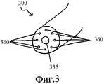
Фиг.3 представляет собой вид в аксонометрии многоканальной трубки в соответствии с иллюстративным вариантом выполнения настоящего изобретения;Figure 3 is a perspective view of a multi-channel tube in accordance with an illustrative embodiment of the present invention;
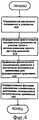
Фиг.4 представляет собой блок-схему, иллюстрирующую способ управления пониженным давлением на участке ткани в соответствии с иллюстративным вариантом выполнения настоящего изобретения;4 is a flowchart illustrating a method for controlling reduced pressure in a tissue site in accordance with an illustrative embodiment of the present invention;
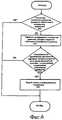
Фиг.5 представляет собой блок-схему, иллюстрирующую способ управления пониженным давлением на участке ткани в соответствии с иллюстративным вариантом выполнения настоящего изобретения;5 is a flowchart illustrating a method for controlling reduced pressure in a tissue site in accordance with an illustrative embodiment of the present invention;
Фиг.6 представляет собой блок-схему, иллюстрирующую способ управления пониженным давлением на участке ткани в соответствии с иллюстративным вариантом выполнения настоящего изобретения; и6 is a flowchart illustrating a method for controlling reduced pressure in a tissue site in accordance with an illustrative embodiment of the present invention; and
Фиг.7 представляет собой блок-схему, иллюстрирующую способ управления пониженным давлением на участке ткани в соответствии с иллюстративным вариантом выполнения настоящего изобретения.7 is a flowchart illustrating a method for controlling reduced pressure in a tissue site in accordance with an illustrative embodiment of the present invention.
ПОДРОБНОЕ ОПИСАНИЕ ПРЕДПОЧТИТЕЛЬНОГО ВАРИАНТА ВЫПОЛНЕНИЯDETAILED DESCRIPTION OF THE PREFERRED EMBODIMENT
В последующем детальном описании предпочтительных вариантов выполнения делается ссылка на сопровождающие чертежи, которые являются частью этого описания и на которых посредством иллюстрации показаны конкретные предпочтительные варианты выполнения, в которых может быть осуществлено изобретение. Эти варианты выполнения описаны достаточно подробно, чтобы позволить специалистам осуществить изобретение на практике, при этом подразумевается, что могут быть осуществлены и другие варианты выполнения и что могут быть выполнены логические, структурные, механические, электрические и химические изменения, не отступая от сущности или объема изобретения. Чтобы избежать деталей, не нужных специалистам для осуществления изобретения, в описании может быть опущена конкретная информация, известная специалистам. Последующее детальное описание не должно, поэтому, пониматься в ограничивающем смысле, при этом область настоящего изобретения определяется только приложенной формулой изобретения.In the following detailed description of preferred embodiments, reference is made to the accompanying drawings, which are part of this description and which show by way of illustration specific preferred embodiments in which the invention may be practiced. These embodiments are described in sufficient detail to enable those skilled in the art to put the invention into practice, it being understood that other embodiments may be implemented and that logical, structural, mechanical, electrical and chemical changes can be made without departing from the spirit or scope of the invention . In order to avoid details that are not needed by those skilled in the art, specific information known to those skilled in the art may be omitted from the description. The following detailed description should not, therefore, be understood in a limiting sense, while the scope of the present invention is defined only by the attached claims.
Иллюстративные описанные здесь варианты выполнения предусматривают устройство и способ для управления пониженным давлением на участке ткани. Пониженное давление в целом относится к давлению, меньшему, чем давление окружающей среды на участке ткани, который подвергается лечению. В большинстве случаев это пониженное давление будет меньше, чем атмосферное давление в месте, в котором расположен пациент. Хотя термины «вакуум» и «отрицательное давление» могут быть использованы, чтобы описывать давление, приложенное к участку ткани, фактическое давление, приложенное к участку ткани, может быть значительно меньше, чем давление, обычно приписываемое полному вакууму. В соответствии с этим определением, увеличение пониженного давления или вакуумного давления относится к относительному уменьшению абсолютного давления, тогда как уменьшение пониженного давления или вакуумного давления относится к относительному увеличению абсолютного давления.The exemplary embodiments described herein provide a device and method for controlling reduced pressure in a tissue site. Reduced pressure generally refers to pressure lower than the ambient pressure on the tissue site that is being treated. In most cases, this reduced pressure will be less than atmospheric pressure at the place where the patient is located. Although the terms “vacuum” and “negative pressure” can be used to describe the pressure applied to the tissue site, the actual pressure applied to the tissue site can be significantly less than the pressure usually attributed to full vacuum. According to this definition, an increase in reduced pressure or vacuum pressure refers to a relative decrease in absolute pressure, while a decrease in reduced pressure or vacuum pressure refers to a relative increase in absolute pressure.
Устройство содержит источник пониженного давления, который создает пониженное давление. Источник пониженного давления представляет собой любое устройство, выполненное с возможностью создания пониженного давления. Пониженное давление подают к участку ткани через трубку подачи. Устройство содержит единственный датчик давления. Датчик давления представляет собой любое устройство, выполненное с возможностью измерения или определения давления. Единственный датчик давления определяет фактическое пониженное давление на участке ткани. В одном варианте выполнения единственный датчик давления представляет собой только один-единственный датчик давления, содержащийся в устройстве.The device contains a source of reduced pressure, which creates a reduced pressure. The source of reduced pressure is any device configured to create reduced pressure. The reduced pressure is supplied to the tissue site through the feed tube. The device contains a single pressure sensor. A pressure sensor is any device configured to measure or determine pressure. A single pressure sensor detects the actual reduced pressure on the tissue site. In one embodiment, a single pressure sensor is only one single pressure sensor contained in the device.
Устройство также содержит контроллер. Контроллер представляет собой любое устройство, выполненное с возможностью обработки данных, таких как данные от единственного датчика давления. Контроллер может также управлять работой одного или большего количества элементов устройства. Контроллер определяет чувствительность фактического пониженного давления, измеренного единственным датчиком давления, к увеличению пониженного давления, создаваемого источником пониженного давления.The device also contains a controller. A controller is any device configured to process data, such as data from a single pressure sensor. The controller may also control the operation of one or more elements of the device. The controller determines the sensitivity of the actual reduced pressure measured by a single pressure sensor to the increase in reduced pressure created by the reduced pressure source.
В одном варианте выполнения источник пониженного давления создает уменьшенное пониженное давление, когда фактическое пониженное давление на участке ткани, определенное единственным датчиком давления, превышает расчетное пониженное давление. В другом варианте выполнения источник пониженного давления создает увеличенное пониженное давление, когда расчетное пониженное давление превышает фактическое пониженное давление на участке ткани, определенное единственным датчиком давления.In one embodiment, the reduced pressure source creates reduced reduced pressure when the actual reduced pressure in the tissue site detected by a single pressure sensor exceeds the calculated reduced pressure. In another embodiment, the reduced pressure source creates an increased reduced pressure when the calculated reduced pressure exceeds the actual reduced pressure on the tissue site detected by a single pressure sensor.
Устройство может также содержать обратный клапан, присоединенный к трубке подачи. Обратный клапан представляет собой любой клапан, выполненный с возможностью уменьшения пониженного давления. В этом варианте выполнения обратный клапан может открываться для уменьшения фактического пониженного давления на участке ткани, когда фактическое пониженное давление на участке ткани, определяемое единственным датчиком давления, превышает расчетное пониженное давление на заданное пороговое значение.The device may also include a check valve attached to the feed tube. The non-return valve is any valve configured to reduce reduced pressure. In this embodiment, the check valve may open to reduce the actual reduced pressure in the tissue site when the actual reduced pressure in the tissue site detected by a single pressure sensor exceeds the calculated reduced pressure by a predetermined threshold value.
Как используется здесь в дальнейшем, термин «соединенный» включает соединение через отдельный объект. Например, обратный клапан может быть соединен с трубкой подачи, если и обратный клапан, и обратная трубка присоединены к третьему объекту. Термин «соединенный» также включает значение «непосредственно соединенный», когда два объекта касаются друг друга некоторым образом. Термин «соединенный» также охватывает два или большее количество элементов, которые непрерывны друг с другом, в том смысле, что каждый из элементов выполнен из одной и той же части материала.As used hereinafter, the term "connected" includes a connection through a separate object. For example, a non-return valve may be connected to the supply pipe if both the non-return valve and the non-return pipe are connected to the third object. The term “connected” also includes the meaning “directly connected” when two objects touch each other in some way. The term “connected” also encompasses two or more elements that are continuous with each other, in the sense that each of the elements is made of the same part of the material.
Устройство содержит индикатор. Индикатор представляет собой любое устройство, выполненное с возможностью выдачи сигнала. Например, индикатор может выдавать сигнал пользователю устройства. Индикатор выдает сигнал, когда контроллер определяет, что фактическое пониженное давление, измеренное единственным датчиком давления, не чувствительно к увеличению пониженного давления, создаваемого источником пониженного давления. Под «нечувствительностью» может пониматься как недостаток влияния на фактическое пониженное давление, как измерено единственным датчиком давления, от увеличения пониженного давления, создаваемого источником пониженного давления. Дополнительные подробности относительно нечувствительности фактического пониженного давления, измеренного единственным датчиком давления, показаны в иллюстративных вариантах выполнения, описанных ниже.The device contains an indicator. An indicator is any device configured to provide a signal. For example, an indicator may signal a device user. The indicator emits a signal when the controller determines that the actual reduced pressure measured by a single pressure sensor is not sensitive to the increase in reduced pressure created by the source of reduced pressure. By "insensitivity" it can be understood as a lack of influence on the actual reduced pressure, as measured by a single pressure sensor, from the increase in reduced pressure created by the source of reduced pressure. Further details regarding the insensitivity of the actual reduced pressure measured by a single pressure transducer are shown in the illustrative embodiments described below.
Иллюстративные варианты выполнения также обеспечивают способ управления пониженным давлением на участке ткани. Определяют расчетное пониженное давление. Расчетным пониженным давлением может быть любое пониженное давление, которое установлено пользователем или устройством, таким как контроллер. Определяют фактическое пониженное давление на участке ткани, используя единственный датчик давления. Сравнивают фактическое пониженное давление с расчетным пониженным давлением, чтобы сформировать сравнение. Выполняют функцию управления пониженным давлением, основанную на сравнении. Функция управления пониженным давлением представляет собой любую операцию, функцию или деятельность любых из элементов устройства. Например, функция управления пониженным давлением может быть осуществлена одним или большим количеством элементов устройства. Функция управления пониженным давлением может также быть выполнена пользователем.Illustrative embodiments also provide a method of controlling reduced pressure at a tissue site. The calculated reduced pressure is determined. The calculated reduced pressure may be any reduced pressure set by the user or a device, such as a controller. The actual reduced pressure at the tissue site is determined using a single pressure transducer. The actual reduced pressure is compared with the calculated reduced pressure to form a comparison. Perform low pressure control function based on comparison. The reduced pressure control function is any operation, function, or activity of any of the elements of a device. For example, a reduced pressure control function may be implemented by one or more device elements. The reduced pressure control function can also be performed by the user.
В одном варианте выполнения выполнение функции управления пониженным давлением, основанной на сравнении, включает уменьшение созданного пониженного давления, создаваемого источником пониженного давления в ответ на превышение фактическим пониженным давлением расчетного пониженного давления. В другом варианте выполнения процесс открывает обратный клапан, что уменьшает фактическое пониженное давление на участке ткани в ответ на превышение фактическим пониженным давлением расчетного пониженного давления на заданную пороговую величину. В другом варианте выполнения процесс устраняет созданное пониженное давление путем выключения источника пониженного давления в ответ на превышение фактическим пониженным давлением расчетного пониженного давления на заданную пороговую величину.In one embodiment, performing the comparison-based reduced pressure control function includes reducing the generated reduced pressure created by the reduced pressure source in response to the actual reduced pressure exceeding the calculated reduced pressure. In another embodiment, the process opens a check valve, which reduces the actual reduced pressure in the tissue site in response to the actual reduced pressure exceeding the calculated reduced pressure by a predetermined threshold value. In another embodiment, the process eliminates the created reduced pressure by turning off the source of reduced pressure in response to the actual reduced pressure exceeding the calculated reduced pressure by a predetermined threshold value.
В другом варианте выполнения выполнение функции управления пониженным давлением, основанной на сравнении, включает увеличение созданного пониженного давления, создаваемого источником пониженного давления, в ответ на превышение расчетным пониженным давлением фактического пониженного давления. В этом варианте выполнения процесс может выдать сигнал, используемый как индикатор, в ответ на нечувствительность фактического пониженного давления на участке ткани к увеличению создаваемого пониженного давления.In another embodiment, performing the reduced pressure control function based on the comparison includes increasing the created reduced pressure created by the reduced pressure source in response to the calculated reduced pressure exceeding the actual reduced pressure. In this embodiment, the process may provide a signal used as an indicator in response to the insensitivity of the actual reduced pressure in the tissue site to an increase in the generated reduced pressure.
В одном примере фактическое пониженное давление на участке ткани не чувствительно к увеличению создаваемого пониженного давления, когда фактическое пониженное давление на участке ткани не в состоянии увеличиться в течение заданного периода времени в ответ на увеличение созданного пониженного давления. В другом примере фактическое пониженное давление на участке ткани не чувствительно к увеличению созданного пониженного давления, когда фактическое пониженное давление на участке ткани не в состоянии достигнуть расчетного пониженного давления в течение заданного периода времени в ответ на увеличение созданного пониженного давления. В конкретном неограничивающем примере заданный период времени может быть в диапазоне от 4 до 6 секунд.In one example, the actual reduced pressure at the tissue site is not sensitive to an increase in the generated reduced pressure when the actual reduced pressure at the tissue site is not able to increase for a predetermined period of time in response to an increase in the created reduced pressure. In another example, the actual reduced pressure at the tissue site is not sensitive to an increase in the created reduced pressure when the actual reduced pressure at the tissue site is not able to reach the calculated reduced pressure within a predetermined period of time in response to an increase in the created reduced pressure. In a specific non-limiting example, a predetermined period of time may be in the range of 4 to 6 seconds.
На Фиг.1 изображена блок-схема устройства для управления пониженным давлением на участке ткани в соответствии с иллюстративным вариантом выполнения настоящего изобретения. Конкретно, Фиг.1 показывает систему 100 лечения пониженным давлением для управления пониженным давлением, подаваемым к участку 105 ткани.Figure 1 shows a block diagram of a device for controlling reduced pressure on a tissue site in accordance with an illustrative embodiment of the present invention. Specifically, FIG. 1 shows a reduced pressure treatment system 100 for controlling reduced pressure applied to a tissue site 105.
Система 100 может использоваться для применения лечения пониженным давлением к участку 105 ткани. Участок 105 ткани может быть физической тканью любого человека, животного или другого организма, включая костную ткань, жировую ткань, мышечную ткань, кожную ткань, сосудистую ткань, соединительную ткань, хрящ, сухожилия, связки или любую другую ткань. Тогда как участок 105 ткани может включать рану, больную ткань или дефектную ткань, участок ткани может также включать здоровую ткань, которая не поранена, не больна или не дефектна. Приложение пониженного давления к участку 105 ткани может быть использовано для обеспечения дренажа эксудата и других жидкостей от участка 105 ткани, а также для способствования росту дополнительной ткани. В случае, в котором участок 105 ткани является участком раны, рост гранулированной ткани и удаление эксудатов и бактерий способствует исцелению раны. Применение пониженного давления к не пораненной или не дефектной ткани, включая здоровую ткань, может быть использовано, чтобы способствовать росту ткани, которая может быть собрана и пересажена в другое местоположение ткани.System 100 can be used to apply reduced pressure treatment to tissue site 105. Tissue section 105 may be the physical tissue of any person, animal, or other organism, including bone tissue, adipose tissue, muscle tissue, skin tissue, vascular tissue, connective tissue, cartilage, tendons, ligaments, or any other tissue. Whereas the tissue site 105 may include a wound, diseased tissue or defective tissue, the tissue site may also include healthy tissue that is not injured, not diseased or not defective. The application of reduced pressure to the tissue site 105 can be used to provide drainage of exudate and other fluids from the tissue site 105, as well as to promote the growth of additional tissue. In the case where the tissue site 105 is a wound site, the growth of granular tissue and the removal of exudates and bacteria contribute to the healing of the wound. Applying reduced pressure to non-injured or non-defective tissue, including healthy tissue, can be used to promote tissue growth, which can be collected and transplanted to another tissue location.
Пониженное давление, которое приложено к участку 105 ткани, создается источником 110 пониженного давления. Источник 110 может быть насосом любого типа, которым управляют вручную, механически или электрически. Неограничивающие примеры источника 110 включают устройства, которые приводятся в действие запасенной энергией и которые способны к созданию пониженного давления. Примеры таких приводимых в действие запасенной энергией источников пониженного давления включают, без ограничения, насосы, приводимые в действие пьезоэлектрической энергией, энергией пружины, солнечной энергией, кинетической энергией, энергией, запасенной в конденсаторах, энергией сгорания и энергией, созданной в цикле Стерлинга или другом аналогичном цикле. Другие примеры источника 110 пониженного давления включают устройства, которые приводятся в действие вручную, такие как сильфонные насосы, перистальтические насосы, диафрагменные насосы, насосы с ротационными лопастями, линейные поршневые насосы, пневматические насосы, гидравлические насосы, ручные насосы, ножные насосы и активируемые вручную насосы, такие как используются с активируемыми вручную аэрозольными распылителями. Тем не менее, другие устройства и процессы, которые могут быть использованы или включены в источник 110 пониженного давления, включают шприцы, винтовой шпиндель, храповики, устройства, управляемые часовым механизмом, устройства, управляемые маятником, ручные генераторы, осмотические процессы, теплонагревающие процессы и процессы, в которых вакуумные давления создаются конденсацией.The reduced pressure that is applied to the tissue site 105 is created by the reduced pressure source 110. The source 110 may be any type of pump that is controlled manually, mechanically or electrically. Non-limiting examples of source 110 include devices that are driven by stored energy and which are capable of generating reduced pressure. Examples of such energy-driven reduced pressure sources include, but are not limited to, pumps driven by piezoelectric energy, spring energy, solar energy, kinetic energy, energy stored in capacitors, combustion energy, and energy generated in a Sterling cycle or other similar cycle. Other examples of reduced pressure source 110 include manually operated devices such as bellows pumps, peristaltic pumps, diaphragm pumps, rotary vane pumps, linear piston pumps, pneumatic pumps, hydraulic pumps, hand pumps, foot pumps, and manually activated pumps such as those used with manually activated aerosol dispensers. However, other devices and processes that can be used or included in the reduced pressure source 110 include syringes, screw spindles, ratchets, clock-controlled devices, pendulum-controlled devices, hand-held generators, osmotic processes, heat-generating processes and processes in which vacuum pressures are created by condensation.
В другом варианте выполнения источник 110 пониженного давления может содержать насос, который приводится в действие химической реакцией. Таблетка, раствор, спрей или другой механизм доставки могут быть доставлены к насосу и использоваться для инициации химической реакции. Тепло, создаваемое химической реакцией, может быть использовано для приведения в действие насоса для создания пониженного давления. В другом варианте выполнения для приведения в действие насоса для создания пониженного давления используется находящийся под давлением газовый баллон, такой как баллон с CO2. В еще другом варианте выполнения источник 110 пониженного давления может быть насосом, управляемым от аккумулятора. Предпочтительно насос использует небольшое количество мощности и способен работать в течение длительного периода времени от одного заряда аккумулятора.In another embodiment, the reduced pressure source 110 may include a pump that is driven by a chemical reaction. A tablet, solution, spray or other delivery mechanism can be delivered to the pump and used to initiate a chemical reaction. The heat generated by the chemical reaction can be used to drive the pump to create a reduced pressure. In another embodiment, a pressurized gas cylinder, such as a CO2 cylinder, is used to drive the pump to create a reduced pressure. In yet another embodiment, the reduced pressure source 110 may be a battery driven pump. Preferably, the pump uses a small amount of power and is able to operate for a long period of time on a single charge of the battery.
Источник 110 пониженного давления обеспечивает пониженным давлением участок 105 ткани через повязку 115. Повязка 115 содержит магистраль 120, которая может быть помещена рядом с участком 105 ткани или в контакте с ней. Магистраль 120 может быть биологически совместимым пористым материалом, который может быть помещен в контакте с участком 105 ткани и распределять пониженное давление к участку 105 ткани. Магистраль 120 может быть выполнена из пены, марли, войлочной циновки или любого другого материала, подходящего для конкретного биологического применения. Магистраль 120 может содержать множество проточных каналов или проходов, чтобы облегчить распределение пониженного давления или текучих сред к участку 105 ткани или от него.The reduced pressure source 110 provides reduced pressure to the tissue site 105 through the dressing 115. The dressing 115 comprises a line 120 that can be placed adjacent to or in contact with the tissue site 105. The line 120 may be a biocompatible porous material that can be placed in contact with the tissue site 105 and distribute reduced pressure to the tissue site 105. Line 120 may be made of foam, gauze, felt mat, or any other material suitable for a particular biological application. The line 120 may comprise a plurality of flow channels or passages to facilitate the distribution of reduced pressure or fluids to or from the tissue site 105.
В одном варианте выполнения магистраль 120 представляет собой пористую пену и содержит множество связанных ячеек или пор, которые действуют как проточные каналы. Пористый пенопласт может быть сетчатым пенополиуретаном с открытыми ячейками, таким как GranuFoam, изготовляемая компанией Kinetic Concepts, Inc. из Сан-Антонио, Техас. Если используется пенопласт с открытой ячейкой, то пористость может изменяться, но предпочтительно имеет значение приблизительно между 400 и 600 микронов. Проточные каналы обеспечивают проточное сообщение повсюду в части магистрали 120, имеющей открытые ячейки. Ячейки и проточные каналы могут быть однородными по форме и размеру или могут содержать структурные или случайные изменения по форме и размеру. Изменения в форме и размере ячеек магистрали сказываются на изменениях в проточных каналах, при этом такие характеристики могут быть использованы для изменения характеристик потока текучей среды через магистраль 120.In one embodiment, the line 120 is a porous foam and contains many associated cells or pores that act as flow channels. The porous foam may be an open-cell mesh polyurethane foam such as GranuFoam manufactured by Kinetic Concepts, Inc. from San Antonio, Texas. If an open cell foam is used, the porosity may vary, but preferably has a value between about 400 and 600 microns. Flow channels provide flow communication throughout a portion of line 120 having open cells. The cells and flow channels may be uniform in shape and size, or may contain structural or random changes in shape and size. Changes in the shape and size of the cells of the line affect changes in the flow channels, and such characteristics can be used to change the characteristics of the fluid flow through the line 120.
В одном варианте выполнения магистраль 120 может дополнительно содержать части, которые включают «закрытые ячейки». Эти части с закрытыми ячейками содержат множество ячеек, большинство из которых не сообщаются проточно со смежными ячейками. Части с закрытыми ячейками могут быть выборочно расположены в магистрали 120, чтобы предотвратить передачу текучих сред через периметрические поверхности магистрали 120.In one embodiment, line 120 may further comprise parts that include “closed cells”. These closed-cell parts contain many cells, most of which do not communicate flowing with adjacent cells. Closed cell portions may be selectively located in line 120 to prevent fluid from flowing through the perimeter surfaces of line 120.
Магистраль 120 может также быть изготовлена из саморассасывающихся материалов, которые не надо удалять из тела пациента после использования системы 100 лечения пониженным давлением. Подходящие саморассасывающиеся материалы могут включать, без ограничения, полимерную смесь полимолочной кислоты (ПМК) и полигликоликовой кислоты (ПГК). Полимерная смесь может также включать, без ограничения, поликарбонаты, полифумараты и капралактоны. Магистраль 120 может далее служить каркасом для роста новых клеток, или каркасный материал может быть использован совместно с магистралью 120, чтобы способствовать росту клеток. Каркас представляет собой вещество или структуру, используемую для увеличения или способствования росту ячеек или формированию ткани, как, например, трехмерная пористая структура, которая обеспечивает матрицу для роста клеток. Иллюстративные примеры каркасных материалов включают фосфат кальция, коллаген, МПК/ПГК, коралл гидрокси апатиты, карбонаты, или обработанные материалы аллотрансплантата. В одном примере каркасный материал имеет высокую фракцию пустот (то есть высокое содержание воздуха).The line 120 may also be made of self-absorbable materials that do not need to be removed from the patient’s body after using the reduced pressure treatment system 100. Suitable self-absorbable materials may include, without limitation, a polymer mixture of polylactic acid (PMA) and polyglycolic acid (PHA). The polymer mixture may also include, without limitation, polycarbonates, polyfumarates and capralactones. Trunk 120 may further serve as a scaffold for the growth of new cells, or scaffold material can be used in conjunction with trunk 120 to promote cell growth. A framework is a substance or structure used to increase or promote cell growth or tissue formation, such as, for example, a three-dimensional porous structure that provides a matrix for cell growth. Illustrative examples of frame materials include calcium phosphate, collagen, IPC / PGA, coral hydroxy apatites, carbonates, or processed allograft materials. In one example, the carcass material has a high fraction of voids (i.e., high air content).
В других вариантах выполнения магистраль 120 может быть выполнена из пористых гидрогелей или материалов, формирующих гидрогель, текстиля, такого как ткани, керамики, слоистых материалов, биопрепаратов, биополимеров, пробковых материалов и кровоостанавливающих повязок. В качестве альтернативы капельки могут быть помещены в контакт с участком 105 ткани и использоваться для распределения пониженного давления.In other embodiments, line 120 may be made of porous hydrogels or hydrogel forming materials, textiles such as fabrics, ceramics, laminate, biologics, biopolymers, cork materials, and hemostatic dressings. Alternatively, droplets may be placed in contact with tissue site 105 and used to distribute reduced pressure.
Повязка 115 также содержит уплотнительный элемент 125. Магистраль 120 может быть прикреплена к участку 105 ткани с использованием уплотнительного элемента 125. Уплотнительный элемент 125 может быть покрытием, которое используется для закрепления магистрали 120 на участке 105 ткани. В то время как уплотнительный элемент 125 может быть непроницаемым или полупроницаемым, в одном примере уплотнительный элемент 125 способен к поддержанию пониженного давления на участке 105 ткани после установки уплотнительного элемента 125 поверх магистрали 120. Уплотнительный элемент 125 может быть гибкой салфеткой или пленкой, выполненной из состава, основанного на силиконе, акрилате, гидрогеле или формирующем гидрогель материале, или любом другом биологически совместимом материале, который имеет характеристики непроницаемости или проницаемости, требуемые для участка 105 ткани. Уплотнительный элемент 125 может быть выполнен из гидрофобного материала, чтобы предотвратить поглощение влажности уплотнительным элементом 125.The dressing 115 also includes a sealing member 125. The trunk 120 may be attached to the tissue portion 105 using the sealing member 125. The sealing member 125 may be a coating that is used to secure the trunk 120 to the tissue portion 105. While the sealing element 125 may be impermeable or semi-permeable, in one example, the sealing element 125 is capable of maintaining reduced pressure in the tissue portion 105 after installing the sealing element 125 over the line 120. The sealing element 125 may be a flexible wipe or film made from the composition based on silicone, acrylate, hydrogel or hydrogel forming material, or any other biocompatible material that has impermeability or permeability characteristics emosti required to tissue site 105. The sealing element 125 may be made of a hydrophobic material to prevent moisture absorption by the sealing element 125.
Вместо того чтобы быть выполненным в форме «листа», такой как форма салфетки, уплотнительный элемент 125 может быть выполнен в «наливаемой» или «распыляемой» форме и прикладывается к магистрали 120 после размещения магистрали 120 в контакте с участком 105 ткани. Точно так же уплотнительный элемент 125 может содержать устройство, которое помещают на магистраль 120 и участок 105 ткани, чтобы обеспечить герметизирующие функциональные возможности, включая, но не ограничиваясь, аспирационную насадку, гипсовую повязку и вакуумный колпак.Instead of being in the form of a “sheet”, such as a napkin shape, the sealing element 125 can be made in a “poured” or “sprayed” form and applied to the line 120 after placing the line 120 in contact with the tissue section 105. Similarly, the sealing element 125 may include a device that is placed on the line 120 and the tissue section 105 to provide sealing functionality, including, but not limited to, an aspiration nozzle, plaster cast, and a vacuum hood.
В одном варианте выполнения уплотнительный элемент 125 предназначен для обеспечения уплотнительного соединения с тканью, окружающей магистраль 120 и участок 105 ткани. Уплотнительное соединение может быть образовано пластырем, помещенным вдоль периметра уплотнительного элемента 125 или на любой части уплотнительного элемента 125, чтобы закрепить уплотнительный элемент 125 на магистрали 120 или на ткани, окружающей участок 105 ткани. Пластырь может быть предварительно помещен на уплотнительном элементе 125 или может быть распылен или иным способом нанесен на уплотнительный элемент 125 непосредственно до размещения уплотнительного элемента 125.In one embodiment, the sealing element 125 is designed to provide a sealing connection with the tissue surrounding the line 120 and the tissue section 105. The sealing joint may be formed by a patch placed along the perimeter of the sealing member 125 or on any part of the sealing member 125 to secure the sealing member 125 to the line 120 or to the fabric surrounding the tissue portion 105. The patch may be pre-placed on the sealing member 125, or may be sprayed or otherwise applied onto the sealing member 125 immediately prior to placement of the sealing member 125.
Как альтернатива клейкому уплотнителю, уплотнительное соединение может быть образовано обертыванием по периферии области, смежной с участком 105 ткани, посредством уплотнительного элемента 125. Например, если участок 105 ткани расположен на конечности пациента, удлиненная салфетка или «драповая лента» могут быть многократно обернуты вокруг магистрали 120 и области, окружающей участок 105 ткани, чтобы обеспечить герметичное соединение. В качестве альтернативы, герметичное соединение между уплотнительным элементом 125 и тканью, окружающей участок 105 ткани, может быть обеспечено с помощью пониженного давления, приложенного системой 100 лечения пониженным давлением. В этом варианте выполнения периметр уплотнительного элемента 125 может быть «вакуумным» образом присоединен к коже пациента. В еще одном варианте выполнения уплотнительный элемент 125 может быть пришит к ткани, окружающей участок 105 ткани, чтобы обеспечить герметичное соединение.As an alternative to the adhesive seal, the seal connection can be formed by wrapping around the periphery of the area adjacent to the tissue section 105 by means of the sealing element 125. For example, if the tissue section 105 is located on the patient’s limb, an elongated tissue or “draped tape” can be wrapped multiple times around the line 120 and the area surrounding the tissue site 105 to provide a sealed connection. Alternatively, a tight connection between the sealing member 125 and the tissue surrounding the tissue portion 105 can be achieved by the reduced pressure applied by the reduced pressure treatment system 100. In this embodiment, the perimeter of the sealing element 125 can be "vacuum" attached to the skin of the patient. In yet another embodiment, the sealing member 125 may be sewn to the fabric surrounding the tissue portion 105 to provide a sealed connection.
В некоторых случаях, уплотнительный элемент 125 не обязательно должен герметизировать участок 105 ткани. Например, участок 105 ткани может быть способным к «самогерметизации», чтобы поддерживать пониженное давление. В случае подкожных и глубоких ран ткани, каверн и свищей, поддержание пониженного давления на участке 105 ткани может быть возможным без использования уплотнительного элемента 125. Так как ткань часто включает или окружает эти типы участков ткани, ткань, окружающая указанный участок ткани, эффективно действует в качестве герметизирующего элемента.In some cases, the sealing element 125 does not have to seal the tissue portion 105. For example, tissue site 105 may be self-sealing to maintain reduced pressure. In the case of subcutaneous and deep wounds of the tissue, cavities and fistulas, maintaining a reduced pressure on the tissue site 105 may be possible without the use of a sealing member 125. Since tissue often includes or surrounds these types of tissue sites, the tissue surrounding the tissue site effectively acts in as a sealing element.
Пониженное давление, создаваемое источником 110 пониженного давления, может быть приложено к участку 105 ткани, используя трубку 130 источника и трубку 135 подачи. Трубка 130 источника и трубка 135 подачи могут быть любой трубкой, через которую могут протекать газ, жидкость, гель или другая текучая среда. Например, эксудат от участка 105 ткани может протекать через трубку 135 подачи. На Фиг.1 трубопровод 130 источника соединяет источник 110 пониженного давления с контейнером 140, а трубка 135 подачи соединяет контейнер 140 с повязкой 115. Однако в другом варианте выполнения источник 135 пониженного давления может быть непосредственно соединен с повязкой 115, используя трубку 135 подачи.The reduced pressure created by the reduced pressure source 110 may be applied to the tissue portion 105 using the source tube 130 and the feed tube 135. The source tube 130 and the supply tube 135 may be any tube through which gas, liquid, gel or other fluid can flow. For example, exudate from tissue site 105 may flow through feed tube 135. 1, a source conduit 130 connects a reduced pressure source 110 to a container 140, and a supply tube 135 connects the container 140 to a bandage 115. However, in another embodiment, the reduced pressure source 135 can be directly connected to the bandage 115 using a supply tube 135.
Трубка 130 источника и трубка 135 подачи могут быть изготовлены из любого материала. Трубки 130 и 135 могут быть либо гибкими, либо негибкими. Кроме того, трубки 130 и 135 могут включать один или более проходов или каналов, через которые может протекать текучая среда. Например, трубка 135 подачи может включать два канала. В этом примере один канал может использоваться для прохода эксудата от участка 105 ткани к контейнеру 140. Другой канал может использоваться для подачи текучих сред, таких как воздух, антибактериальные агенты, противовирусные средства, агенты, содействующие росту клеток, ирригационные жидкости или другие химически активные агенты, в участок 105 ткани. Источник текучей среды, из которого вытекают эти текучие среды, не изображен на Фиг.1. Дополнительные детали относительно включения многоканальных трубок в систему 100 лечения пониженным давлением даны ниже.The source tube 130 and the feed tube 135 may be made of any material. Tubes 130 and 135 may be either flexible or inflexible. In addition, tubes 130 and 135 may include one or more passages or channels through which fluid may flow. For example, the supply tube 135 may include two channels. In this example, one channel can be used to pass exudate from tissue site 105 to container 140. Another channel can be used to supply fluids such as air, antibacterial agents, antiviral agents, cell growth promoting agents, irrigation fluids, or other chemically active agents. , to the tissue site 105. The source of fluid from which these fluids flow is not shown in FIG. Additional details regarding the incorporation of multi-channel tubes into the reduced pressure treatment system 100 are given below.
В одном варианте выполнения трубка 135 подачи присоединена к магистрали 120 через соединительный элемент 145. Соединительный элемент 145 обеспечивает проход жидкости от магистрали 120 к трубке 135 подачи и наоборот. Например, эксудаты, собранные от участка 105 ткани с использованием магистрали 120, могут войти в трубку 135 через соединительный элемент 145. В другом варианте выполнения система 100 лечения пониженным давлением не содержит соединительного элемента 145. В этом варианте выполнения трубка 135 подачи может быть вставлена непосредственно в уплотнительный элемент 125 или магистраль 120 таким образом, чтобы конец трубки 135 подачи был расположен рядом или в контакте с магистралью 120.In one embodiment, the supply pipe 135 is connected to the line 120 through a connecting element 145. The connecting element 145 allows fluid to pass from the line 120 to the supply pipe 135 and vice versa. For example, exudates collected from tissue site 105 using line 120 may enter tube 135 via connector 145. In another embodiment, the reduced pressure treatment system 100 does not include connector 145. In this embodiment, the delivery tube 135 can be inserted directly into the sealing element 125 or line 120 so that the end of the feed tube 135 is adjacent or in contact with the line 120.
Система 100 содержит контейнер 140. Жидкость, такая как эксудат, может протекать через трубку 135 подачи от участка 105 ткани в контейнер 140. Контейнер 115 может быть любым устройством или полостью, выполненной с возможностью содержания текучей среды, такой как газы и жидкости, а также текучих сред, которые содержат твердые частицы. Например, контейнер 115 может содержать эксудаты от участка 105 ткани. Трубки 130 и 135 могут быть непосредственно соединены с контейнером 140 или могут быть соединены с контейнером 140 через соединитель, такой как соединитель 150.The system 100 comprises a container 140. A fluid, such as an exudate, can flow through a feed tube 135 from a tissue portion 105 to a container 140. The container 115 may be any device or cavity configured to contain a fluid, such as gases and liquids, and fluids that contain solid particles. For example, container 115 may contain exudates from tissue site 105. Tubes 130 and 135 may be directly connected to container 140 or may be connected to container 140 through a connector, such as connector 150.
Контейнер 140 может быть гибким или твердым контейнером, сумкой или мешком, проточно сообщающимся с магистралью 120 через трубку 135 подачи. Контейнер 140 может быть отдельным контейнером или может быть функционально объединен с источником 110 пониженного давления, чтобы собирать эксудат и текучие среды. В иллюстративном варианте выполнения, в котором в качестве источника 110 пониженного давления используется ручной насос, такой как сильфонный насос, камера с переменным объемом, которая создает пониженное давление, может также служить контейнером 140, собирая текучую среду по мере расширения камеры. Контейнер 140 может содержать одну-единственную камеру для сбора текучих сред, или, в качестве альтернативы, может содержать несколько камер. Для захвата текучей среды или управления ей, когда она собрана, внутри контейнера 140 может быть помещен влагопоглотитель или абсорбирующий материал. В отсутствие контейнера 140 может быть использован способ управления эксудатом и другими текучими средами, в котором текучие среды, особенно те, которые являются растворимыми водой, могут испаряться из магистрали 120.The container 140 may be a flexible or solid container, bag, or pouch flowing in fluid communication with line 120 through a feed tube 135. The container 140 may be a separate container or may be operatively combined with a reduced pressure source 110 to collect exudate and fluids. In an illustrative embodiment, in which a hand pump, such as a bellows pump, is used as the reduced pressure source 110, a variable volume chamber that generates a reduced pressure may also serve as a container 140, collecting fluid as the chamber expands. The container 140 may comprise a single fluid collection chamber, or, alternatively, may comprise several chambers. To capture or control the fluid when it is collected, a desiccant or absorbent material may be placed inside the container 140. In the absence of container 140, a method for controlling exudate and other fluids can be used in which fluids, especially those that are water soluble, can evaporate from line 120.
Система 100 содержит датчик 155 давления. Датчик 155 давления определяет фактическое пониженное давление на участке 105 ткани. В одном неограничивающем примере датчик 155 давления представляет собой кремниевый пьезорезистивный датчик абсолютного давления. В одном варианте выполнения датчик 155 является единственным датчиком давления, содержащимся в системе 100. В этом варианте выполнения система 100 не содержит никакого другого датчика давления кроме датчика 155.System 100 includes a pressure sensor 155. The pressure sensor 155 detects the actual reduced pressure at the tissue site 105. In one non-limiting example, the pressure sensor 155 is a silicon piezoresistive absolute pressure sensor. In one embodiment, sensor 155 is the only pressure sensor contained in system 100. In this embodiment, system 100 does not contain any other pressure sensor other than sensor 155.
Датчик 155 определяет пониженное давление на участке 105 ткани через управляющую трубку 160. Управляющая трубка 160 представляет собой любую трубку, через которую может протекать газ. Управляющая трубка 160 может быть изготовлена из любого материала. Управляющая трубка 160 может быть либо гибкой, либо негибкой. Кроме того, управляющая трубка 160 может включать один или большее количество проходов или каналов, через которые может протекать текучая среда.The sensor 155 detects a reduced pressure at the tissue site 105 through the control tube 160. The control tube 160 is any tube through which gas can flow. The control tube 160 may be made of any material. The control tube 160 may be either flexible or inflexible. In addition, the control tube 160 may include one or more passages or channels through which fluid may flow.
На Фиг.1 управляющая трубка 160 изображена проходящей через соединитель 150. Однако размещение управляющей трубки 160 может быть различно, чтобы приспособить конкретные потребности и применения. Например, управляющая трубка 160 может быть перенаправлена через контейнер 140 вдоль наружной поверхности контейнера 140, или может обходить контейнер 140. Конец управляющей трубки 160, который противоположен датчику 155 давления, может быть соединен с магистралью 120 через соединитель 145. В другом примере управляющая трубка 160 может быть вставлена непосредственно в уплотнительный элемент 125 или магистраль 120 таким образом, чтобы конец управляющей трубки 160 находился рядом или в контакте с магистралью 120.1, control tube 160 is shown extending through connector 150. However, the placement of control tube 160 may be different to accommodate specific needs and applications. For example, the control tube 160 may be redirected through the container 140 along the outer surface of the container 140, or may bypass the container 140. The end of the control tube 160, which is opposite to the pressure sensor 155, may be connected to the line 120 through the connector 145. In another example, the control tube 160 can be inserted directly into the sealing element 125 or line 120 so that the end of the control tube 160 is adjacent or in contact with the line 120.
В другом варианте выполнения как трубка 135 подачи, так и управляющая трубка 160 представляют собой каналы в единственной многоканальной трубке. Как трубка 130 источника, так и управляющая трубка 160 могут также быть каналами в единственной многоканальной трубке. В этом примере, в котором источник 110 пониженного давления присоединен к магистрали 120, используя только трубку 135 подачи, единственная многоканальная трубка может быть использована для присоединения как источника 110 пониженного давления, так и датчика 155 давления к магистрали 120. Дополнительные детали относительно варианта выполнения с несколькими каналами будут описаны ниже со ссылкой на Фиг.2 и Фиг.3.In another embodiment, both the supply tube 135 and the control tube 160 are channels in a single multi-channel tube. Both the source tube 130 and the control tube 160 may also be channels in a single multi-channel tube. In this example, in which the reduced pressure source 110 is connected to the line 120 using only the supply pipe 135, a single multi-channel pipe can be used to connect both the reduced pressure source 110 and the pressure sensor 155 to the line 120. Additional details regarding the embodiment with several channels will be described below with reference to FIG. 2 and FIG. 3.
Датчик 155 может быть расположен в любом месте в системе 100. На Фиг.1 датчик 155 показан расположенным удаленно от участка 105 ткани. В этом примере пониженное давление на участке 105 ткани может быть определено от удаленно расположенного датчика 155 через управляющую трубку 160, через которую может проходить поток газа. Также в этом примере датчик давления может быть непосредственно или опосредованно присоединен к другим удаленно расположенным элементам системы 100 лечения пониженным давлением, таким как источник 110 пониженного давления, контейнер 140 или любой другой проиллюстрированный элемент системы 100. В другом примере датчик 155 может быть помещен рядом с участком 105 ткани. В этом примере для определения давления на участке 105 ткани датчику 155 может и не потребоваться использование управляющей трубки 160. В одном неограничивающем примере датчик 155 непосредственно присоединен к магистрали 120 или размещен между уплотнительным элементом 125 и магистралью 120.The sensor 155 can be located anywhere in the system 100. In FIG. 1, the sensor 155 is shown located remotely from the tissue site 105. In this example, the reduced pressure at the tissue site 105 can be detected from a remotely located sensor 155 through a control tube 160 through which a gas stream can pass. Also in this example, the pressure sensor may be directly or indirectly connected to other remotely located elements of the reduced pressure treatment system 100, such as a reduced pressure source 110, a container 140, or any other illustrated element of the system 100. In another example, the sensor 155 may be placed adjacent to patch 105 of fabric. In this example, the sensor 155 may not need to use a control tube 160 to determine the pressure in the tissue portion 105 of the fabric. In one non-limiting example, the sensor 155 is directly connected to the line 120 or placed between the sealing member 125 and the line 120.
Система 100 содержит клапан 165 управляющей трубки. Клапан 165 управляющей трубки может быть присоединен к управляющей трубке 160. Клапан 165 может быть любым клапаном, выполненным с возможностью сброса пониженного давления в управляющей трубке 160. Неограничивающие примеры клапана 165 включают пневматический соленоидный клапан, пропорциональный клапан или механический клапан.System 100 includes a control tube valve 165. The control tube valve 165 may be coupled to the control pipe 160. The valve 165 may be any valve configured to relieve reduced pressure in the control pipe 160. Non-limiting examples of the valve 165 include a pneumatic solenoid valve, a proportional valve, or a mechanical valve.
В одном примере клапан 165 может вручную управляться человеком. В другом примере клапан 165 может управляться контроллером 170. В одном варианте выполнения клапан 165 может быть открыт, чтобы уменьшить пониженное давление в управляющей трубке 160, когда в управляющей трубке 160 обнаружена блокировка. Такая блокировка может произойти, например, когда эксудат или другая текучая среда от участка 105 ткани забивают управляющую трубку 160. Путем сброса пониженного давления в управляющей трубке 160 через клапан 165 блокировка трубки 160 может быть снята.In one example, valve 165 may be manually controlled by a person. In another example, valve 165 may be controlled by controller 170. In one embodiment, valve 165 may be opened to reduce underpressure in control pipe 160 when blockage is detected in control pipe 160. Such blocking can occur, for example, when the exudate or other fluid from the tissue site 105 is blocked by the control tube 160. By relieving the reduced pressure in the control tube 160 through the valve 165, the blocking of the tube 160 can be released.
Система 100 также содержит обратный клапан 175. Обратный клапан 175 может быть клапаном, который присоединен к любому элементу или любой комбинации этих элементов из трубки 130 источника, контейнера 140, соединителя 150, трубки 135 подачи, соединителя 145, источника 110 пониженного давления или повязки 115. Обратный клапан 175 может представлять собой любой тип клапана, выполненного с возможностью сброса пониженного давления на участке 105 ткани. Неограничивающие примеры обратного клапана 175 включают пневматический соленоидный клапан, пропорциональный клапан или механический клапан. В одном примере обратный клапан 175 может быть открыт для сброса пониженного давления на участке 105 ткани. Обратный клапан 175 может также быть использован для управления пониженным давлением на участке 105 ткани. Дополнительные детали, касающиеся использования обратного клапана 175 и других элементов системы 100 для управления пониженным давлением на участке 105 ткани, приведены ниже.The system 100 also includes a check valve 175. The check valve 175 may be a valve that is connected to any element or any combination of these elements from a source tube 130, a container 140, a connector 150, a feed tube 135, a connector 145, a reduced pressure source 110 or a bandage 115 The check valve 175 may be any type of valve configured to relieve reduced pressure at a tissue site 105. Non-limiting examples of check valve 175 include a pneumatic solenoid valve, a proportional valve, or a mechanical valve. In one example, a non-return valve 175 may be open to relieve reduced pressure at a tissue site 105. Non-return valve 175 may also be used to control reduced pressure at tissue site 105. Additional details regarding the use of check valve 175 and other elements of system 100 for controlling reduced pressure at tissue site 105 are provided below.
Система лечения пониженным давлением содержит контроллер 170. Контроллер 170 представляет собой любое устройство, выполненное с возможностью обработки данных, таких как данные от датчика 155 давления. Контроллер 170 может также управлять работой одного или большего количества элементов системы 100 лечения пониженным давлением, таких как источник 110 пониженного давления, обратный клапан 175, клапан 165 управляющей трубки, датчик 155 давления или индикатор 180. В одном варианте выполнения контроллер 170 получает и обрабатывает данные, такие как данные от датчика 155, и управляет работой одного или большего количества элементов системы 100 для управления пониженным давлением на участке 105 ткани.The reduced pressure treatment system comprises a controller 170. The controller 170 is any device configured to process data, such as data from a pressure sensor 155. Controller 170 may also control the operation of one or more elements of the reduced pressure treatment system 100, such as reduced pressure source 110, check valve 175, pilot tube valve 165, pressure sensor 155, or indicator 180. In one embodiment, controller 170 receives and processes data such as data from sensor 155, and controls the operation of one or more elements of system 100 for controlling reduced pressure at tissue site 105.
В одном варианте выполнения контроллер 170 определяет расчетное пониженное давление для участка 105 ткани. Расчетное пониженное давление может быть задаваемым пользователем пониженным давлением для участка 105 ткани. Расчетное пониженное давление может также быть определено контроллером 170. В одном примере расчетное пониженное давление представляет собой пониженное давление, которое обеспечивает эффективное лечение участка 105 ткани и принимает во внимание проблемы безопасности, связанные с приложением пониженного давления к участку 105 ткани.In one embodiment, the controller 170 determines an estimated reduced pressure for the tissue site 105. The estimated reduced pressure may be a user-defined reduced pressure for the tissue site 105. The calculated reduced pressure can also be determined by the controller 170. In one example, the calculated reduced pressure is a reduced pressure that provides effective treatment of the tissue site 105 and takes into account safety concerns associated with applying reduced pressure to the tissue site 105.
В одном примере датчик 155 определяет пониженное давление на участке 105 ткани. Результат измерения пониженного давления может быть получен контроллером 170 отдатчика 155. Контроллер 170 может сравнить пониженное давление, полученное от датчика 155, с расчетным пониженным давлением, чтобы сформировать сравнение. Контроллер 170 может затем выполнить функцию управления пониженным давлением, основанную на сравнении, или поручить элементу системы 100 лечения пониженным давлением выполнить функцию управления пониженным давлением, основанную на сравнении.In one example, the sensor 155 detects a reduced pressure at the tissue site 105. The result of measuring the reduced pressure may be obtained by the controller 170 of the transmitter 155. The controller 170 may compare the reduced pressure received from the sensor 155 with the calculated reduced pressure to form a comparison. The controller 170 may then perform the reduced pressure control function based on the comparison, or instruct the element of the low pressure treatment system 100 to perform the reduced pressure control function based on the comparison.
В одном варианте выполнения контроллер 170 при выполнении функции управления пониженным давлением, основанной на сравнении, уменьшает созданное пониженное давление, создаваемое источником 110 пониженного давления в ответ на превышение фактическим пониженным давлением расчетного пониженного давления. Например, если источник 110 пониженного давления имеет электропривод или является другим электрическим источником пониженного давления, которым управляют, двигатель или электрический процесс можно замедлить таким образом, чтобы источник 110 пониженного давления создавал уменьшенное значение пониженного давления. В другом неограничивающем примере, если источник 110 пониженного давления является химически приводимым в действие источником пониженного давления, химический процесс, приводящий в действие источник 110, может быть замедлен или изменен, чтобы уменьшить величину пониженного давления, создаваемого источником 110.In one embodiment, the controller 170, when performing the reduced pressure control function based on the comparison, reduces the created reduced pressure created by the reduced pressure source 110 in response to the actual reduced pressure exceeding the calculated reduced pressure. For example, if the reduced pressure source 110 is electrically driven or is another controlled electric source of reduced pressure, the engine or electrical process can be slowed down so that the reduced pressure source 110 produces a reduced reduced pressure value. In another non-limiting example, if the reduced pressure source 110 is a chemically driven reduced pressure source, the chemical process driving the source 110 may be slowed down or modified to reduce the amount of reduced pressure created by the source 110.
В другом варианте выполнения контроллер 170 открывает обратный клапан 175, чтобы уменьшить пониженное давление на участке 105 ткани, в ответ на превышение фактическим пониженным давлением, как измерено датчиком 155, расчетного пониженного давления на заданное пороговое значение. Заданное пороговое значение может быть определено пользователем или элементом системы 100 лечения пониженным давлением, таким как контроллер 170. В одном примере заданное пороговое значение представляет собой пороговое значение, которое помогает обеспечивать безопасность ткани на участке 105 ткани. Например, заданное пороговое значение может быть задано таким образом, что фактическое пониженное давление на участке 105 ткани, которое превышает расчетное пониженное давление на указанное заданное пороговое значение, может повлиять на безопасность ткани на участке 105 ткани. Таким образом, этот вариант выполнения может быть осуществлен как предохранительный механизм, используя один-единственный датчик 155 давления.In another embodiment, the controller 170 opens the check valve 175 to reduce the reduced pressure at the tissue site 105, in response to the actual reduced pressure being exceeded, as measured by the sensor 155, the calculated reduced pressure by a predetermined threshold value. The predetermined threshold value may be determined by a user or an element of the reduced pressure treatment system 100, such as a controller 170. In one example, the predetermined threshold value is a threshold value that helps to ensure tissue safety at the tissue site 105. For example, a predetermined threshold value may be set such that an actual reduced pressure in the tissue portion 105 that exceeds the calculated reduced pressure by the specified predetermined threshold value may affect tissue safety in the tissue portion 105. Thus, this embodiment can be implemented as a safety mechanism using a single pressure sensor 155.
В другом варианте выполнения контроллер 170 выключает или перекрывает источник 110 пониженного давления в ответ на превышение фактическим пониженным давлением, как измерено датчиком 155, расчетного пониженного давления на заданное пороговое значение. Выключение или перекрытие источника 110 пониженного давления уменьшает пониженное давление на участке 105 ткани. В одном примере заданное пороговое значение, за которым источник 110 пониженного давления выключается, больше, чем, или меньше, чем заданное пороговое значение, за которым обратный клапан 175 открывается, как описано в предыдущем варианте выполнения. Таким образом, в этом примере используется двухуровневый механизм безопасности, чтобы обеспечить безопасность ткани на участке 105 ткани. В другом примере заданное пороговое значение, за которым источник 110 пониженного давления выключается, является тем же самым заданным пороговым значением, за которым обратный клапан 175 открывается.In another embodiment, the controller 170 turns off or shuts off the reduced pressure source 110 in response to the actual reduced pressure being exceeded, as measured by the gauge 155, of the calculated reduced pressure by a predetermined threshold value. Turning off or shutting off the reduced pressure source 110 reduces the reduced pressure at the tissue site 105. In one example, a predetermined threshold value beyond which the reduced pressure source 110 is turned off is greater than or less than a predetermined threshold value beyond which the check valve 175 opens, as described in the previous embodiment. Thus, in this example, a two-tier safety mechanism is used to ensure tissue safety at the tissue site 105. In another example, the predetermined threshold value beyond which the reduced pressure source 110 is turned off is the same predetermined threshold value beyond which the non-return valve 175 opens.
В другом примере контроллер 170 при выполнении функции управления пониженным давлением, основанной на сравнении, увеличивает созданное пониженное давление, создаваемое источником 110. Например, если источник 110 имеет электропривод или является другим электрическим источником пониженного давления, ход двигателя или электрический процесс может быть ускорен таким образом, чтобы источник 110 создавал увеличенное количество пониженного давления. В другом неограничивающем примере, если источник 110 пониженного давления является химически приводимым в действие источником пониженного давления, химический процесс, приводящий в действие источник 110, может быть ускорен или изменен, чтобы увеличить величину пониженного давления, создаваемого источником 110.In another example, the controller 170, when performing the reduced pressure control function based on comparison, increases the created reduced pressure created by the source 110. For example, if the source 110 is electrically driven or is another electric source of reduced pressure, the engine or the electrical process can be accelerated in this way so that the source 110 creates an increased amount of reduced pressure. In another non-limiting example, if the reduced pressure source 110 is a chemically driven reduced pressure source, the chemical process driving the source 110 can be accelerated or modified to increase the amount of reduced pressure created by the source 110.
В другом варианте выполнения контроллер 170 определяет чувствительность фактического пониженного давления на участке 105 ткани, как измерено датчиком 155, на увеличение создаваемого пониженного давления источником 110 пониженного давления. В одном примере контроллер 170 может обнаружить, когда пониженное давление, создаваемое источником пониженного давления, увеличивается или уменьшается. Например, контроллер 170 может быть выполнен с возможностью определения, когда частота вращения двигателя, скорость химической реакции или скорость сжатия источника 110 увеличилась или уменьшилась. Другие параметры, которые могут быть определены контроллером 170 для определения такого увеличения или уменьшения, включают ток, потребляемый двигателем, который может указывать на производительность насоса. Также может быть определен уровень мощности или модуляция ширины импульса, необходимые для двигателя, чтобы доставить необходимую величину пониженного давления к участку 105 ткани. Контроллер 170 также может быть выполнен с возможностью принятия решения о том, что пониженное давление, создаваемое источником пониженного давления, увеличилось или уменьшилось, основываясь на сравнении между фактическим пониженным давлением, измеренным датчиком 155, и расчетным пониженным давлением.In another embodiment, the controller 170 determines the sensitivity of the actual reduced pressure at the tissue site 105, as measured by the sensor 155, to increase the generated reduced pressure by the reduced pressure source 110. In one example, the controller 170 may detect when the reduced pressure created by the reduced pressure source increases or decreases. For example, the controller 170 may be configured to determine when the engine speed, chemical reaction rate, or compression rate of source 110 has increased or decreased. Other parameters that may be determined by controller 170 to determine such an increase or decrease include current drawn by the motor, which may indicate pump performance. The power level or pulse width modulation necessary for the engine can also be determined to deliver the required reduced pressure to the tissue site 105. The controller 170 may also be configured to decide that the reduced pressure generated by the reduced pressure source has increased or decreased based on a comparison between the actual reduced pressure measured by the sensor 155 and the calculated reduced pressure.
В одном варианте выполнения контроллер 170 поручает индикатору 180 выдать сигнал в ответ на нечувствительность фактического пониженного давления на участке 105 ткани, как измерено датчиком 155 давления, к увеличению создаваемого пониженного давления. В одном варианте выполнения индикатор 180 представляет собой светодиод, или «СИД». В этом варианте выполнения индикатор 180 загорается в ответ на нечувствительность фактического пониженного давления на участке 105 ткани к увеличению создаваемого пониженного давления.In one embodiment, controller 170 instructs indicator 180 to provide a signal in response to the insensitivity of the actual reduced pressure at tissue site 105, as measured by pressure sensor 155, to increase the generated reduced pressure. In one embodiment, indicator 180 is an LED, or “LED.” In this embodiment, the indicator 180 lights up in response to the insensitivity of the actual reduced pressure in the tissue portion 105 to an increase in the generated reduced pressure.
В другом варианте выполнения индикатор 180 представляет собой испускающее звук устройство, такое как громкоговоритель. В этом варианте выполнения индикатор 180 испускает звук в ответ на нечувствительность фактического пониженного давления на участке 105 ткани к увеличению создаваемого пониженного давления.In another embodiment, indicator 180 is a sound-emitting device, such as a speaker. In this embodiment, the indicator 180 emits a sound in response to the insensitivity of the actual reduced pressure in the tissue portion 105 to an increase in the generated reduced pressure.
В другом варианте выполнения фактическое пониженное давление на участке 105 ткани является нечувствительным к увеличению создаваемого пониженного давления, когда фактическое пониженное давление на участке 105 ткани не в состоянии увеличиться в течение заданного периода времени, в ответ на увеличение создаваемого пониженного давления. Такая нечувствительность может указывать на то, что один или большее количество элементов системы 100 лечения пониженным давлением, такие как трубка 135 подачи или трубка 130 источника, заблокированы или имеют течь. Например, жидкость, такая как эксудат от участка 105 ткани, может забить трубку 135 подачи или трубку 130 источника. В другом примере в каком-либо месте вдоль трубки 135 подачи или трубки 130 источника, возможно, произошел разрыв.In another embodiment, the actual reduced pressure at the tissue site 105 is insensitive to an increase in the generated reduced pressure when the actual reduced pressure at the tissue site 105 is not able to increase for a predetermined period of time in response to an increase in the generated reduced pressure. Such insensitivity may indicate that one or more elements of the reduced pressure treatment system 100, such as the supply tube 135 or the source tube 130, are blocked or leaking. For example, a fluid, such as exudate from the tissue site 105, may clog the feed tube 135 or source tube 130. In another example, a break may have occurred anywhere along the feed tube 135 or source tube 130.
Заданный период времени может представлять собой любой период времени и может быть установлен пользователем системы 100 лечения пониженным давлением или элементом системы 100 лечения пониженным давлением 100, таким как контроллер 170. В одном примере заданный период времени находится в диапазоне от одной секунды до десяти секунд, или от четырех секунд до шести секунд. В одном конкретном неограничивающем примере заданный период времени составляет пять секунд.The predetermined time period may be any period of time and may be set by the user of the reduced pressure treatment system 100 or an element of the reduced pressure treatment system 100, such as the controller 170. In one example, the predetermined time period is in the range of one second to ten seconds, or from four seconds to six seconds. In one specific non-limiting example, a predetermined period of time is five seconds.
В другом варианте выполнения фактическое пониженное давление на участке 105 ткани не чувствительно к увеличению создаваемого пониженного давления, когда фактическое пониженное давление на участке 105 ткани не в состоянии достигнуть расчетного пониженного давления в течение заданного периода времени, в ответ на увеличение создаваемого пониженного давления. Как и в вышеописанном варианте выполнения, такая нечувствительность может указывать на то, что один или большее количество элементов системы 100 лечения пониженным давлением, такие как трубка 135 подачи или трубка 130 источника, заблокированы или имеют течь.In another embodiment, the actual reduced pressure in the tissue section 105 is not sensitive to an increase in the generated reduced pressure when the actual reduced pressure in the tissue section 105 is not able to achieve the calculated reduced pressure within a predetermined period of time, in response to an increase in the created reduced pressure. As in the above embodiment, such insensitivity may indicate that one or more elements of the reduced pressure treatment system 100, such as the supply tube 135 or the source tube 130, are blocked or have a leak.
В другом варианте выполнения настоящего изобретения, если источник пониженного давления 110 представляет собой вакуумный насос и двигатель, то для измерения скорости вращения насоса или двигателя датчик может быть присоединен к вакуумному насосу или двигателю. Измерения, выполненные датчиком, могут быть использованы для того, чтобы сделать заключение о величине давления, подаваемого насосом, обеспечивая, таким образом, механизм для определения наличия утечки или блокировки и определения различия между ними. Например, определение утечки может быть выполнено путем осуществления контроля скорости либо насоса, либо двигателя, либо и того и другого вместе. Если происходит утечка во время применения лечения пониженным давлением, либо скорость насоса, либо частота вращения двигателя, либо и то и другое вместе вероятно увеличатся, указывая на то, что насос создает больше пониженного давления. Если происходит блокировка, то скорость либо насоса, либо двигателя с большой вероятностью уменьшится. Выходной сигнал от датчика частоты вращения насоса или двигателя может быть использован контроллером 170, чтобы выдать сигнал с использованием индикатора 180 во время состояния блокировки или утечки.In another embodiment of the present invention, if the reduced pressure source 110 is a vacuum pump and an engine, then a sensor may be coupled to the vacuum pump or engine to measure the rotation speed of the pump or engine. The measurements made by the sensor can be used to make a conclusion about the amount of pressure supplied by the pump, thus providing a mechanism for detecting a leak or blockage and determining the difference between them. For example, leak detection can be done by monitoring the speed of either the pump, or the motor, or both. If a leak occurs during the application of the reduced pressure treatment, either the pump speed, or the engine speed, or both, will likely increase, indicating that the pump creates more reduced pressure. If blocking occurs, then the speed of either the pump or the motor is likely to decrease. The output from the pump or motor speed sensor may be used by controller 170 to provide a signal using indicator 180 during a block or leak condition.
В одном конкретном иллюстративном примере источник 110 пониженного давления содержит двигатель, способный развивать определенную скорость. В этом примере датчик может регистрировать скорость двигателя. Индикатор 180 может выдать сигнал, когда скорость двигателя изменяется на пороговую величину. Пороговая величина может быть любым значением и может быть установлена пользователем системы 100 лечения пониженным давлением или элементом системы 100 лечения пониженным давлением 100, таким как контроллер 170. Пороговая величина может быть выражена как конечная величина, в процентах или в любой их комбинации.In one specific illustrative example, the reduced pressure source 110 comprises an engine capable of a specific speed. In this example, the sensor can record engine speed. Indicator 180 may give a signal when the engine speed changes by a threshold value. The threshold value can be any value and can be set by the user of the reduced pressure treatment system 100 or an element of the reduced pressure treatment system 100, such as the controller 170. The threshold value can be expressed as a final value, in percent, or any combination thereof.
Обращаясь теперь к Фиг.2, в соответствии с иллюстративным вариантом выполнения настоящего изобретения представлен вид в аксонометрии многоканальной трубки. Конкретно, Фиг.2 изображает многоканальную трубку 200, которая может быть использована в системе лечения пониженным давлением, такой как система 100, изображенная на Фиг.1.Turning now to FIG. 2, in accordance with an illustrative embodiment of the present invention, a perspective view of a multi-channel tube is provided. Specifically, FIG. 2 depicts a
Многоканальная трубка 200 имеет два канала. Конкретно, трубка 200 имеет каналы 235 и 260. Хотя трубка 200 имеет два канала 235 и 160, она может иметь любое число каналов, такое как три, четыре или десять.
В одном варианте выполнения один из каналов 235 и 260, такой как канал 235, является трубкой подачи или трубкой 130 источника, такой как трубка 135 подачи и трубка 130 источника, изображенные на Фиг.1. В другом варианте выполнения один из каналов 235 и 260, такой как канал 260, является управляющей трубкой, такой как управляющая трубка 160, изображенная на Фиг.1. Путем выполнения комбинации трубки подачи, трубки источника и управляющей трубки как каналов в одной единственной многоканальной трубке, количество отдельных трубок, содержащихся в системе лечения пониженным давлением, может быть сокращено. Уменьшенное количество трубок упрощает использование пользователем системы лечения пониженным давлением и снижает неудобства, связанные с переносом системы лечения пониженным давлением.In one embodiment, one of the
Обратимся теперь к Фиг.3, которая представляет собой вид в аксонометрии многоканальной трубки, изображенной в соответствии с иллюстративным вариантом выполнения настоящего изобретения. Конкретно, Фиг.3 изображает многоканальную трубку 300, которая может быть осуществлена в системе лечения пониженным давлением, такой как система 100, изображенная на Фиг.1. Трубка 300 может быть неограничивающим примером многоканальной трубки 200, показанной на Фиг.2.Turning now to FIG. 3, which is a perspective view of a multi-channel tube shown in accordance with an illustrative embodiment of the present invention. Specifically, FIG. 3 depicts a
Трубка 300 имеет девять каналов. Конкретнее, трубка 300 имеет канал 335 и периферийные каналы 360. Хотя в трубке 300 периферийные каналы 360 изображены как круглые каналы 335, каналы в трубке 300 могут иметь любую пространственную конфигурацию относительно друг друга.
В одном варианте выполнения один из каналов 335 и 360, такой как канал 335, является трубкой подачи или трубкой источника, такой как трубка 135 подачи и трубка 130 источника, изображенные на Фиг.1. В другом варианте выполнения один из каналов 335 и 360, такой как любой или все каналы 360, является управляющей трубкой, такой как управляющая трубка 160, изображенная на Фиг.1. Как и для трубки 300, показанной на Фиг.3, путем включения любой комбинации трубки подачи, трубки источника и управляющей трубки, как каналов в трубке 300, количество отдельных трубок, включенных в систему лечения пониженным давлением, может быть сокращено, чтобы повысить удобство и простоту использования системы лечения пониженным давлением, в которую включена многоканальная трубка.In one embodiment, one of the
На Фиг.4 в соответствии с иллюстративным вариантом выполнения настоящего изобретения изображена блок-схема, иллюстрирующая способ управления пониженным давлением на участке ткани. Способ, проиллюстрированный на Фиг.4, может быть осуществлен контроллером, таким как контроллер 170, показанный на Фиг.1, в соединении с другими элементами системы лечения пониженным давлением, такими как элементы системы 100, изображенной на Фиг.1.4, in accordance with an illustrative embodiment of the present invention, a flowchart illustrating a method for controlling reduced pressure in a tissue site is shown. The method illustrated in FIG. 4 may be implemented by a controller, such as the controller 170 shown in FIG. 1, in conjunction with other elements of a reduced pressure treatment system, such as elements of a system 100 of FIG. 1.
Способ начинают путем определения расчетного пониженного давления (этап 405). В способе определяют фактическое пониженное давление на участке ткани, используя один-единственный датчик давления (этап 410). Затем сравнивают фактическое пониженное давление с расчетным пониженным давлением, чтобы сформировать сравнение (этап 415). Выполняют функцию управления пониженным давлением, основанную на сравнении (этап 420).The method is started by determining the calculated reduced pressure (step 405). In the method, the actual reduced pressure on the tissue site is determined using a single pressure sensor (step 410). Then, the actual reduced pressure is compared with the calculated reduced pressure to form a comparison (step 415). The reduced pressure control function based on the comparison is performed (block 420).
На Фиг.5 в соответствии с иллюстративным вариантом выполнения настоящего изобретения изображена блок-схема, иллюстрирующая способ управления пониженным давлением на участке ткани. Способ, проиллюстрированный на Фиг.5, может быть осуществлен контроллером, таким как контроллер 170, показанный на Фиг.1, в соединении с другими элементами системы лечения пониженным давлением, такими как элементы системы 100 лечения пониженным давлением, изображенной на Фиг.1. Способ, проиллюстрированный на Фиг.5, обеспечивает иллюстративные варианты выполнения и дополнительные детали в отношении этапов 415 и 420, показанных на Фиг.4.5, in accordance with an illustrative embodiment of the present invention, is a flowchart illustrating a method for controlling reduced pressure in a tissue site. The method illustrated in FIG. 5 may be implemented by a controller, such as the controller 170 shown in FIG. 1, in conjunction with other elements of the reduced pressure treatment system, such as elements of the reduced pressure treatment system 100 shown in FIG. The method illustrated in FIG. 5 provides illustrative embodiments and additional details with respect to steps 415 and 420 shown in FIG. 4.
Способ начинают путем определения, превышает ли фактическое пониженное давление расчетное пониженное давление (этап 505). Если определяют, что фактическое пониженное давление не превышает расчетное пониженное давление, способ заканчивают. Возвращаясь к этапу 505, если определяют, что фактическое пониженное давление превышает расчетное пониженное давление, уменьшают создаваемое пониженное давление, которое создается источником пониженного давления (этап 510).The method is started by determining whether the actual reduced pressure exceeds the calculated reduced pressure (step 505). If it is determined that the actual reduced pressure does not exceed the calculated reduced pressure, the method is completed. Returning to step 505, if it is determined that the actual reduced pressure exceeds the calculated reduced pressure, the created reduced pressure that is created by the reduced pressure source is reduced (step 510).
Определяют, превышает ли фактическое пониженное давление расчетное пониженное давление на заданное пороговое значение (этап 515). Если определяют, что фактическое пониженное давление не превышает расчетное пониженное давление, способ заканчивают. Возвращаясь к этапу 515, если определяют, что фактическое пониженное давление превышает расчетное пониженное давление на заданное пороговое значение, определяют, нужно ли уменьшить пониженное давление путем открытия обратного клапана (этап 520). Если определяют, что нужно уменьшить пониженное давление путем открытия обратного клапана, открывают обратный клапан, чтобы уменьшить фактическое пониженное давление на участке ткани (этап 525).It is determined whether the actual reduced pressure exceeds the calculated reduced pressure by a predetermined threshold value (step 515). If it is determined that the actual reduced pressure does not exceed the calculated reduced pressure, the method is completed. Returning to step 515, if it is determined that the actual reduced pressure exceeds the calculated reduced pressure by a predetermined threshold value, it is determined whether to reduce the reduced pressure by opening the check valve (step 520). If it is determined that the reduced pressure needs to be reduced by opening the check valve, open the check valve to reduce the actual reduced pressure on the tissue site (step 525).
Возвращаясь к этапу 520, если определяют, что не нужно уменьшать пониженное давление путем открытия обратного клапана, определяют, нужно ли уменьшить пониженное давление путем выключения источника пониженного давления (этап 530). Если определяют, что нужно уменьшить пониженное давление путем выключения источника пониженного давления, выключают источник пониженного давления (этап 535). Затем способ заканчивают. Возвращаясь к этапу 530, если определяют, что не нужно уменьшать пониженное давление путем выключения источника пониженного давления, способ заканчивают.Returning to step 520, if it is determined that it is not necessary to reduce the reduced pressure by opening the check valve, it is determined whether to reduce the reduced pressure by turning off the source of reduced pressure (step 530). If it is determined that the reduced pressure needs to be reduced by turning off the reduced pressure source, the reduced pressure source is turned off (step 535). Then the method is completed. Returning to step 530, if it is determined that it is not necessary to reduce the reduced pressure by turning off the reduced pressure source, the method is completed.
На Фиг.6 в соответствии с иллюстративным вариантом выполнения настоящего изобретения изображена блок-схема, иллюстрирующая способ управления пониженным давлением на участке ткани. Способ, проиллюстрированный на Фиг.6, может быть осуществлен контроллером, таким как контроллер 170, показанный на Фиг.1, в соединении с другими элементами системы лечения пониженным давлением, такими как элементы системы 100, изображенные на Фиг.1. Способ, проиллюстрированный на Фиг.5, обеспечивает иллюстративные варианты выполнения и дополнительные детали в отношении этапов 415 и 420, показанных на Фиг.4.6, in accordance with an illustrative embodiment of the present invention, a flowchart illustrating a method for controlling reduced pressure in a tissue site is shown. The method illustrated in FIG. 6 may be carried out by a controller, such as the controller 170 shown in FIG. 1, in conjunction with other elements of the reduced pressure treatment system, such as elements of the system 100 shown in FIG. 1. The method illustrated in FIG. 5 provides illustrative embodiments and additional details with respect to steps 415 and 420 shown in FIG. 4.
Способ начинают, определяя, превышает ли расчетное пониженное давление фактическое пониженное давление (этап 605). Если определяют, что расчетное пониженное давление не превышает фактическое пониженное давление, способ заканчивают. Возвращаясь к этапу 605, если определяют, что расчетное пониженное давление превышает фактическое пониженное давление, увеличивают создаваемое пониженное давление, которое создается источником пониженного давления (этап 610).The method is started by determining whether the calculated reduced pressure exceeds the actual reduced pressure (step 605). If it is determined that the calculated reduced pressure does not exceed the actual reduced pressure, the method is completed. Returning to step 605, if it is determined that the calculated reduced pressure exceeds the actual reduced pressure, the created reduced pressure that is created by the reduced pressure source is increased (step 610).
Определяют, откликается ли фактическое пониженное давление, измеряемое одним-единственным датчиком давления, на увеличение создаваемого пониженного давления (этап 615). Если определяют, что фактическое пониженное давление, измеряемое одним-единственным датчиком давления, откликается на увеличение создаваемого пониженного давления, способ заканчивают. Возвращаясь к этапу 615, если определяют, что фактическое пониженное давление, измеряемое одним-единственным датчиком давления, не откликается на увеличение создаваемого пониженного давления, выдают сигнал с использованием индикатора (этап 620). Затем способ заканчивают.A determination is made whether the actual reduced pressure measured by a single pressure sensor responds to an increase in the generated reduced pressure (step 615). If it is determined that the actual reduced pressure, measured by a single pressure sensor, responds to an increase in the generated reduced pressure, the method is completed. Returning to step 615, if it is determined that the actual reduced pressure measured by a single pressure sensor does not respond to the increase in the generated reduced pressure, a signal is generated using the indicator (step 620). Then the method is completed.
На Фиг.7 в соответствии с иллюстративным вариантом выполнения настоящего изобретения изображена блок-схема, иллюстрирующая способ управления пониженным давлением на участке ткани. Способ, проиллюстрированный на Фиг.7, может быть осуществлен контроллером, таким как контроллер 170, показанный на Фиг.1, в соединении с другими элементами системы лечения пониженным давлением, такими как элементы системы 100, изображенные на Фиг.1. Способ, проиллюстрированный на Фиг.7, обеспечивает иллюстративные варианты выполнения и дополнительные детали в отношении этапов 615 и 620, показанных на Фиг.6.7, in accordance with an illustrative embodiment of the present invention, a flowchart illustrating a method of controlling reduced pressure in a tissue site is shown. The method illustrated in FIG. 7 may be carried out by a controller, such as the controller 170 shown in FIG. 1, in conjunction with other elements of the reduced pressure treatment system, such as elements of the system 100 shown in FIG. 1. The method illustrated in FIG. 7 provides illustrative embodiments and additional details with respect to
Способ начинают, определяя, увеличивается ли фактическое пониженное давление на участке ткани в течение заданного периода времени (этап 705). Если определяют, что фактическое пониженное давление на участке ткани не увеличивается в течение заданного периода времени, выдают сигнал с использованием индикатора (этап 710). Затем способ заканчивают.The method is started by determining whether the actual reduced pressure in the tissue site increases over a predetermined period of time (step 705). If it is determined that the actual reduced pressure in the tissue site does not increase over a predetermined period of time, a signal is generated using the indicator (step 710). Then the method is completed.
Возвращаясь к этапу 705, если определяют, что фактическое пониженное давление увеличивается на участке ткани в течение заданного периода времени, определяют, достигает ли фактическое пониженное давление на участке ткани расчетного пониженного давления в течение заданного периода времени (этап 715). Если определяют, что фактическое пониженное давление на участке ткани не достигает расчетного пониженного давления в течение заданного периода времени, выдают сигнал с использованием индикатора (этап 710). Затем способ заканчивают. Возвращаясь к этапу 715, если определяют, что фактическое пониженное давление на участке ткани не достигает расчетного пониженного давления в течение заданного периода времени, способ тогда заканчивают.Returning to step 705, if it is determined that the actual reduced pressure increases in the tissue site over a predetermined period of time, it is determined whether the actual reduced pressure in the tissue site has reached the estimated reduced pressure within the predetermined time period (step 715). If it is determined that the actual reduced pressure in the tissue site does not reach the estimated reduced pressure within a predetermined period of time, a signal is generated using the indicator (step 710). Then the method is completed. Returning to step 715, if it is determined that the actual reduced pressure in the tissue site does not reach the calculated reduced pressure within a predetermined period of time, the method is then completed.
Блок-схемы и диаграммы в различных изображенных вариантах выполнения иллюстрируют архитектуру, функциональные возможности и принцип работы некоторых возможных вариантов выполнения устройства и способов. В некотором альтернативных вариантах выполнения функция или функции, отмеченные на блок-схеме, могут быть осуществлены не в том порядке, как отмечено на чертежах. Например, в некоторых случаях два блока, показанные по очереди, могут быть выполнены по существу одновременно, или же блоки могут иногда выполняться в обратном порядке, в зависимости от используемых функциональных возможностей.The flowcharts and diagrams in the various illustrated embodiments illustrate the architecture, functionality, and principle of operation of some possible embodiments of the device and methods. In some alternative embodiments, the function or functions indicated in the flowchart may not be implemented in the order indicated in the drawings. For example, in some cases, two blocks shown in turn can be executed essentially simultaneously, or blocks can sometimes be executed in the reverse order, depending on the functionality used.
Иллюстративные варианты выполнения могут быть выполнены так, чтобы обладать легким весом и быть дешевыми, причем эта система потребляет меньше энергии, чем используемые в настоящее время системы лечения пониженным давлением. Снижение размера и веса особенно важно, когда система должна быть использована для лечения ран низкой степени тяжести и ран амбулаторных пациентов. Эти раны и пациенты нуждаются в системе, которая не вызывает неудобств и имеет легкий вес так, чтобы дискомфорт пациенту и помехи перемещению были сведены к минимуму.Exemplary embodiments can be designed to be light weight and cheap, and this system consumes less energy than currently used low pressure treatment systems. Reducing size and weight is especially important when the system should be used to treat low severity wounds and outpatient wounds. These wounds and patients need a system that is comfortable and lightweight so that patient discomfort and disruption to movement are minimized.
Одним путем, с помощью которого стоимость, вес и расход энергии могут быть сведены к минимуму, является измерение давления с помощью только одного датчика. Как было ранее указано, традиционные системы обычно используют два датчика давления: один для измерения давления на участке ткани и другой для измерения давления в источнике пониженного давления. Однако устранение измерения давления датчиком давления в источнике пониженного давления позволяет значительно сократить требуемую электронную схему, а также количество энергии, потребляемой системой. Кроме того, исключаются любые схемы и программное обеспечение, используемые для сравнения показаний двух датчиков. Кроме того, иллюстративные варианты выполнения обеспечивают приложение заданного пониженного давления к ткани, обеспечивая обнаружение и предупреждение о конкретных аномальных состояниях системы с меньшим количеством элементов, чем в предшествующих системах.One way in which cost, weight and energy consumption can be minimized is to measure pressure with just one sensor. As previously stated, conventional systems typically use two pressure sensors: one for measuring pressure in a tissue site and the other for measuring pressure in a reduced pressure source. However, the elimination of pressure measurement by the pressure sensor in the source of reduced pressure can significantly reduce the required electronic circuit, as well as the amount of energy consumed by the system. In addition, any circuits and software used to compare the readings of two sensors are excluded. In addition, illustrative embodiments provide the application of a given reduced pressure to the tissue, providing detection and warning of specific abnormal conditions of a system with fewer elements than in previous systems.
Иллюстративные варианты выполнения также избавляют от необходимости аппроксимировать давление участка ткани, используя измеренное значение в источнике пониженного давления. Кроме того, определение давления непосредственно на участке ткани, когда используется с другими особенностями иллюстративных вариантов выполнения, позволяет системе лечения пониженным давлением определять утечки и блокировки путем наблюдения за изменением давления на участке ткани в ответ на функциональные изменения, создаваемые в источнике пониженного давления.Illustrative embodiments also eliminate the need to approximate the pressure of a tissue site using the measured value at the source of reduced pressure. In addition, the determination of pressure directly on the tissue site, when used with other features of the illustrative embodiments, allows the reduced pressure treatment system to detect leaks and blockages by monitoring pressure changes in the tissue site in response to functional changes created in the source of reduced pressure.
Claims (13)
Translated fromRussianисточник пониженного давления, выполненный с возможностью создания пониженного давления, которое подается к участку ткани через трубку подачи,
один датчик давления, определяющий фактическое пониженное давление на участке ткани,
контроллер, выполненный с возможностью получения данных от указанного датчика давления, причем контроллер выполнен с возможностью определения чувствительности фактического пониженного давления, измеряемого указанным датчиком давления, к увеличению пониженного давления, создаваемого источником пониженного давления, и
индикатор, выполненный с возможностью управления контроллером, причем индикатор выполнен с возможностью испускания сигнала, когда контроллер определяет, что фактическое пониженное давление, измеренное указанным одним датчиком давления, нечувствительно к увеличению пониженного давления, создаваемого источником пониженного давления;
при этом фактическое пониженное давление является нечувствительным к увеличению создаваемого пониженного давления, когда фактическое пониженное давление не в состоянии либо увеличиться в течение заданного периода времени, либо достигнуть расчетного пониженного давления в течение заданного периода времени.1. A device for controlling reduced pressure on a tissue site undergoing reduced pressure therapy, comprising:
a source of reduced pressure, configured to create a reduced pressure that is supplied to the tissue site through the feed tube,
one pressure sensor that detects the actual reduced pressure on the tissue site,
a controller configured to receive data from said pressure sensor, wherein the controller is configured to determine a sensitivity of the actual reduced pressure measured by said pressure sensor to increase the reduced pressure generated by the reduced pressure source, and
an indicator configured to control the controller, the indicator configured to emit a signal when the controller determines that the actual reduced pressure measured by the specified one pressure sensor is insensitive to the increase in reduced pressure created by the source of reduced pressure;
in this case, the actual reduced pressure is insensitive to an increase in the created reduced pressure when the actual reduced pressure is not able to either increase within a predetermined period of time, or to achieve a calculated reduced pressure within a predetermined period of time.
увеличение создаваемого пониженного давления с использованием источника пониженного давления,
определение фактического пониженного давления на участке ткани с использованием одного датчика давления, и
выдачу сигнала с использованием индикатора в ответ на нечувствительность фактического пониженного давления на участке ткани к увеличению создаваемого пониженного давления,
при этом фактическое пониженное давление является нечувствительным к увеличению создаваемого пониженного давления, когда фактическое пониженное давление не в состоянии либо увеличиться в течение заданного периода времени, либо достигнуть расчетного пониженного давления в течение заданного периода времени.11. A method for controlling reduced pressure in a tissue site undergoing reduced pressure therapy, comprising:
an increase in the generated reduced pressure using a source of reduced pressure,
determining the actual reduced pressure in the tissue using one pressure sensor, and
issuing a signal using an indicator in response to the insensitivity of the actual reduced pressure on the tissue site to an increase in the generated reduced pressure,
in this case, the actual reduced pressure is insensitive to an increase in the created reduced pressure when the actual reduced pressure is not able to either increase within a predetermined period of time, or to achieve a calculated reduced pressure within a predetermined period of time.
Applications Claiming Priority (2)
| Application Number | Priority Date | Filing Date | Title |
|---|---|---|---|
| US90055607P | 2007-02-09 | 2007-02-09 | |
| US60/900,556 | 2007-02-09 |
Publications (2)
| Publication Number | Publication Date |
|---|---|
| RU2009124101A RU2009124101A (en) | 2011-03-20 |
| RU2428208C2true RU2428208C2 (en) | 2011-09-10 |
Family
ID=39690401
Family Applications (1)
| Application Number | Title | Priority Date | Filing Date |
|---|---|---|---|
| RU2009124101/14ARU2428208C2 (en) | 2007-02-09 | 2008-02-08 | System and method of low pressure control in tissue area |
Country Status (14)
| Country | Link |
|---|---|
| US (3) | US8409170B2 (en) |
| EP (3) | EP2109472B2 (en) |
| JP (5) | JP5122586B2 (en) |
| KR (1) | KR101217918B1 (en) |
| CN (1) | CN101605568B (en) |
| AU (1) | AU2008216781B2 (en) |
| BR (1) | BRPI0806221A2 (en) |
| CA (1) | CA2673842C (en) |
| IL (1) | IL199778A0 (en) |
| MX (1) | MX2009008397A (en) |
| RU (1) | RU2428208C2 (en) |
| TW (2) | TW201219070A (en) |
| WO (1) | WO2008100440A1 (en) |
| ZA (1) | ZA200904308B (en) |
Cited By (3)
| Publication number | Priority date | Publication date | Assignee | Title |
|---|---|---|---|---|
| US10881764B2 (en) | 2012-03-20 | 2021-01-05 | Smith & Nephew Plc | Controlling operation of a reduced pressure therapy system based on dynamic duty cycle threshold determination |
| RU2752515C2 (en)* | 2016-08-31 | 2021-07-28 | Б. Браун Сёрджикал С.А. | Medical device, mainly for fistula treatment |
| RU2771915C1 (en)* | 2021-04-20 | 2022-05-13 | Алексей Андреевич Евсюков | Apparatus for creating a medium with predetermined characteristics in soft tissue wounds and bandage for implementation of the apparatus |
Families Citing this family (273)
| Publication number | Priority date | Publication date | Assignee | Title |
|---|---|---|---|---|
| GB0224986D0 (en) | 2002-10-28 | 2002-12-04 | Smith & Nephew | Apparatus |
| CN1822874B (en) | 2003-07-22 | 2010-10-13 | 凯希特许有限公司 | Negative pressure wound treatment dressing |
| GB0325129D0 (en) | 2003-10-28 | 2003-12-03 | Smith & Nephew | Apparatus in situ |
| US8062272B2 (en) | 2004-05-21 | 2011-11-22 | Bluesky Medical Group Incorporated | Flexible reduced pressure treatment appliance |
| US10058642B2 (en) | 2004-04-05 | 2018-08-28 | Bluesky Medical Group Incorporated | Reduced pressure treatment system |
| US7909805B2 (en) | 2004-04-05 | 2011-03-22 | Bluesky Medical Group Incorporated | Flexible reduced pressure treatment appliance |
| CA2949821C (en) | 2005-09-06 | 2021-05-18 | Smith & Nephew, Inc. | Self contained wound dressing with micropump |
| US8338402B2 (en)* | 2006-05-12 | 2012-12-25 | Smith & Nephew Plc | Scaffold |
| EP1905465B2 (en) | 2006-09-28 | 2013-11-27 | Smith & Nephew, Inc. | Portable wound therapy system |
| ES2564519T3 (en) | 2006-10-13 | 2016-03-23 | Bluesky Medical Group Inc. | Pressure control of a medical vacuum pump |
| AU2007311028B2 (en)* | 2006-10-17 | 2013-06-27 | Smith & Nephew Plc | Auxiliary powered negative pressure wound therapy apparatuses and methods |
| US7967810B2 (en) | 2006-10-20 | 2011-06-28 | Mary Beth Kelley | Sub-atmospheric wound-care system |
| RU2428208C2 (en) | 2007-02-09 | 2011-09-10 | КейСиАй Лайсензинг Инк. | System and method of low pressure control in tissue area |
| CA2674997C (en) | 2007-02-09 | 2012-08-14 | Kci Licensing, Inc. | A breathable interface system for topical reduced pressure |
| EP2129409B2 (en) | 2007-03-14 | 2021-11-24 | The Board of Trustees of the Leland Stanford Junior University | Devices for application of reduced pressure therapy |
| GB0712736D0 (en)* | 2007-07-02 | 2007-08-08 | Smith & Nephew | Apparatus |
| GB0712764D0 (en) | 2007-07-02 | 2007-08-08 | Smith & Nephew | Carrying Bag |
| GB0712763D0 (en) | 2007-07-02 | 2007-08-08 | Smith & Nephew | Apparatus |
| GB0715259D0 (en) | 2007-08-06 | 2007-09-12 | Smith & Nephew | Canister status determination |
| US9408954B2 (en) | 2007-07-02 | 2016-08-09 | Smith & Nephew Plc | Systems and methods for controlling operation of negative pressure wound therapy apparatus |
| GB0712739D0 (en) | 2007-07-02 | 2007-08-08 | Smith & Nephew | Apparatus |
| US12121648B2 (en) | 2007-08-06 | 2024-10-22 | Smith & Nephew Plc | Canister status determination |
| WO2009067711A2 (en)* | 2007-11-21 | 2009-05-28 | T.J. Smith & Nephew, Limited | Suction device and dressing |
| EP2214612B1 (en) | 2007-11-21 | 2019-05-01 | Smith & Nephew PLC | Wound dressing |
| GB0722820D0 (en) | 2007-11-21 | 2008-01-02 | Smith & Nephew | Vacuum assisted wound dressing |
| ES2715605T3 (en) | 2007-11-21 | 2019-06-05 | Smith & Nephew | Wound dressing |
| US11253399B2 (en) | 2007-12-06 | 2022-02-22 | Smith & Nephew Plc | Wound filling apparatuses and methods |
| GB0723855D0 (en) | 2007-12-06 | 2008-01-16 | Smith & Nephew | Apparatus and method for wound volume measurement |
| US20130096518A1 (en) | 2007-12-06 | 2013-04-18 | Smith & Nephew Plc | Wound filling apparatuses and methods |
| GB0723872D0 (en) | 2007-12-06 | 2008-01-16 | Smith & Nephew | Apparatus for topical negative pressure therapy |
| GB0723874D0 (en)* | 2007-12-06 | 2008-01-16 | Smith & Nephew | Dressing |
| GB2455962A (en) | 2007-12-24 | 2009-07-01 | Ethicon Inc | Reinforced adhesive backing sheet, for plaster |
| US8377017B2 (en) | 2008-01-03 | 2013-02-19 | Kci Licensing, Inc. | Low-profile reduced pressure treatment system |
| US8366692B2 (en) | 2008-01-08 | 2013-02-05 | Richard Scott Weston | Sustained variable negative pressure wound treatment and method of controlling same |
| AU2009214439B2 (en)* | 2008-02-14 | 2014-09-25 | Solventum Intellectual Properties Company | Devices and methods for treatment of damaged tissue |
| AU2009221772B2 (en) | 2008-03-05 | 2015-01-22 | Solventum Intellectual Properties Company | Dressing and method for applying reduced pressure to and collecting and storing fluid from a tissue site |
| US8021347B2 (en) | 2008-07-21 | 2011-09-20 | Tyco Healthcare Group Lp | Thin film wound dressing |
| US9033942B2 (en)* | 2008-03-07 | 2015-05-19 | Smith & Nephew, Inc. | Wound dressing port and associated wound dressing |
| US8298200B2 (en) | 2009-06-01 | 2012-10-30 | Tyco Healthcare Group Lp | System for providing continual drainage in negative pressure wound therapy |
| AU2009223037A1 (en) | 2008-03-12 | 2009-09-17 | Smith & Nephew Plc | Negative pressure dressing and method of using same |
| EP2977067B1 (en) | 2008-03-13 | 2020-12-09 | 3M Innovative Properties Company | Apparatus for applying reduced pressure to a tissue site on a foot |
| US8152785B2 (en) | 2008-03-13 | 2012-04-10 | Tyco Healthcare Group Lp | Vacuum port for vacuum wound therapy |
| US10912869B2 (en) | 2008-05-21 | 2021-02-09 | Smith & Nephew, Inc. | Wound therapy system with related methods therefor |
| US8414519B2 (en) | 2008-05-21 | 2013-04-09 | Covidien Lp | Wound therapy system with portable container apparatus |
| US8177763B2 (en) | 2008-09-05 | 2012-05-15 | Tyco Healthcare Group Lp | Canister membrane for wound therapy system |
| US8257326B2 (en) | 2008-06-30 | 2012-09-04 | Tyco Healthcare Group Lp | Apparatus for enhancing wound healing |
| WO2010005709A1 (en) | 2008-07-08 | 2010-01-14 | Tyco Healthcare Group Lp | Portable negative pressure wound therapy device |
| ES2658263T3 (en) | 2008-08-08 | 2018-03-09 | Smith & Nephew, Inc. | Continuous fiber wound dressing |
| US8366691B2 (en)* | 2008-08-08 | 2013-02-05 | Kci Licensing, Inc | Reduced-pressure treatment systems with reservoir control |
| US8216198B2 (en) | 2009-01-09 | 2012-07-10 | Tyco Healthcare Group Lp | Canister for receiving wound exudate in a negative pressure therapy system |
| US8251979B2 (en) | 2009-05-11 | 2012-08-28 | Tyco Healthcare Group Lp | Orientation independent canister for a negative pressure wound therapy device |
| US8827983B2 (en) | 2008-08-21 | 2014-09-09 | Smith & Nephew, Inc. | Sensor with electrical contact protection for use in fluid collection canister and negative pressure wound therapy systems including same |
| US9414968B2 (en) | 2008-09-05 | 2016-08-16 | Smith & Nephew, Inc. | Three-dimensional porous film contact layer with improved wound healing |
| US8425478B2 (en)* | 2008-09-18 | 2013-04-23 | Kci Licensing, Inc. | Multi-layer dressings, systems, and methods for applying reduced pressure at a tissue site |
| US8158844B2 (en) | 2008-10-08 | 2012-04-17 | Kci Licensing, Inc. | Limited-access, reduced-pressure systems and methods |
| CN102215799B (en) | 2008-11-14 | 2013-09-18 | 凯希特许有限公司 | Fluid bag, system and method for storing fluid from a tissue site |
| CA2744548C (en) | 2008-11-25 | 2017-06-13 | Spiracur Inc. | Device for delivery of reduced pressure to body surfaces |
| US8361043B2 (en) | 2009-01-07 | 2013-01-29 | Spiracur Inc. | Reduced pressure therapy of the sacral region |
| US8162907B2 (en) | 2009-01-20 | 2012-04-24 | Tyco Healthcare Group Lp | Method and apparatus for bridging from a dressing in negative pressure wound therapy |
| US8728045B2 (en)* | 2009-03-04 | 2014-05-20 | Spiracur Inc. | Devices and methods to apply alternating level of reduced pressure to tissue |
| SE533726C2 (en)* | 2009-04-30 | 2010-12-14 | Moelnlycke Health Care Ab | Apparatus with negative pressure for treatment of wounds |
| US9421309B2 (en) | 2009-06-02 | 2016-08-23 | Kci Licensing, Inc. | Reduced-pressure treatment systems and methods employing hydrogel reservoir members |
| US20110196321A1 (en) | 2009-06-10 | 2011-08-11 | Tyco Healthcare Group Lp | Fluid Collection Canister Including Canister Top with Filter Membrane and Negative Pressure Wound Therapy Systems Including Same |
| US20100324516A1 (en)* | 2009-06-18 | 2010-12-23 | Tyco Healthcare Group Lp | Apparatus for Vacuum Bridging and/or Exudate Collection |
| EP2461863B1 (en) | 2009-08-05 | 2016-07-27 | Covidien LP | Surgical wound dressing incorporating connected hydrogel beads having an embedded electrode therein |
| WO2011043863A2 (en) | 2009-08-13 | 2011-04-14 | Michael Simms Shuler | Methods and dressing systems for promoting healing of injured tissue |
| AU2010298770B2 (en)* | 2009-09-22 | 2015-05-28 | Molnlycke Health Care Ab | An apparatus and method for controlling the negative pressure in a wound |
| AU2010341491B2 (en) | 2009-12-22 | 2015-05-14 | Smith & Nephew, Inc. | Apparatuses and methods for negative pressure wound therapy |
| CA2784138C (en) | 2010-01-20 | 2018-04-24 | Kci Licensing, Inc. | Wound-connection pads for fluid instillation and negative pressure wound therapy, and systems and methods |
| US8430867B2 (en) | 2010-03-12 | 2013-04-30 | Kci Licensing, Inc. | Reduced-pressure dressing connection pads, systems, and methods |
| US8882730B2 (en)* | 2010-03-12 | 2014-11-11 | Kci Licensing, Inc. | Radio opaque, reduced-pressure manifolds, systems, and methods |
| US8454580B2 (en)* | 2010-03-12 | 2013-06-04 | Kci Licensing, Inc. | Adjustable reduced-pressure wound coverings |
| US8814842B2 (en) | 2010-03-16 | 2014-08-26 | Kci Licensing, Inc. | Delivery-and-fluid-storage bridges for use with reduced-pressure systems |
| US8604265B2 (en) | 2010-04-16 | 2013-12-10 | Kci Licensing, Inc. | Dressings and methods for treating a tissue site on a patient |
| US9061095B2 (en) | 2010-04-27 | 2015-06-23 | Smith & Nephew Plc | Wound dressing and method of use |
| USRE48117E1 (en) | 2010-05-07 | 2020-07-28 | Smith & Nephew, Inc. | Apparatuses and methods for negative pressure wound therapy |
| US8795246B2 (en) | 2010-08-10 | 2014-08-05 | Spiracur Inc. | Alarm system |
| US8753322B2 (en) | 2010-08-10 | 2014-06-17 | Spiracur Inc. | Controlled negative pressure apparatus and alarm mechanism |
| GB201015656D0 (en)* | 2010-09-20 | 2010-10-27 | Smith & Nephew | Pressure control apparatus |
| US9526920B2 (en) | 2010-10-12 | 2016-12-27 | Smith & Nephew, Inc. | Medical device |
| US8986269B2 (en)* | 2010-11-11 | 2015-03-24 | Ulcerx Medical Inc. | Wound leakage vacuum collection device |
| CA2814873C (en)* | 2010-11-17 | 2018-04-24 | Kci Licensing, Inc. | Systems and methods for managing reduced pressure at a plurality of wound sites |
| CN102058932B (en)* | 2010-12-20 | 2013-03-06 | 惠州市华阳医疗电子有限公司 | Negative pressure control device and control method of negative pressure treatment system |
| USD714433S1 (en) | 2010-12-22 | 2014-09-30 | Smith & Nephew, Inc. | Suction adapter |
| RU2016111981A (en) | 2010-12-22 | 2018-11-27 | Смит Энд Нефью, Инк. | DEVICE AND METHOD FOR TREATING RAS WITH NEGATIVE PRESSURE |
| GB2488749A (en) | 2011-01-31 | 2012-09-12 | Systagenix Wound Man Ip Co Bv | Laminated silicone coated wound dressing |
| AU2012228360B2 (en)* | 2011-03-11 | 2015-08-20 | Lohmann & Rauscher Gmbh & Co. Kg | Vacuum system and endoscopy arrangement for endoscopic vacuum therapy |
| US9302034B2 (en) | 2011-04-04 | 2016-04-05 | Smith & Nephew, Inc. | Negative pressure wound therapy dressing |
| GB201106491D0 (en) | 2011-04-15 | 2011-06-01 | Systagenix Wound Man Ip Co Bv | Patterened silicone coating |
| US9474838B2 (en)* | 2011-04-20 | 2016-10-25 | Kci Licensing, Inc. | System and method for managing reduced pressure delivered to a tissue site |
| US9067003B2 (en) | 2011-05-26 | 2015-06-30 | Kalypto Medical, Inc. | Method for providing negative pressure to a negative pressure wound therapy bandage |
| RU2611760C2 (en) | 2011-06-07 | 2017-02-28 | Смит Энд Нефью Плс | Wound contacting elements and methods of their use |
| CA2843133C (en)* | 2011-07-26 | 2020-08-25 | Smith & Nephew Plc | Systems and methods for controlling operation of a reduced pressure therapy system |
| JP6083762B2 (en)* | 2011-08-31 | 2017-02-22 | ケーシーアイ ライセンシング インコーポレイテッド | Inline storage pouch for use with body fluids |
| JP6050819B2 (en)* | 2011-09-14 | 2016-12-21 | ケーシーアイ ライセンシング インコーポレイテッド | Pressure reduction system and method using leak detection member |
| US9393354B2 (en) | 2011-11-01 | 2016-07-19 | J&M Shuler Medical, Inc. | Mechanical wound therapy for sub-atmospheric wound care system |
| US9084845B2 (en) | 2011-11-02 | 2015-07-21 | Smith & Nephew Plc | Reduced pressure therapy apparatuses and methods of using same |
| CN103987348B (en) | 2011-12-16 | 2016-05-11 | 凯希特许有限公司 | Releasable Medical Drapes |
| US10940047B2 (en) | 2011-12-16 | 2021-03-09 | Kci Licensing, Inc. | Sealing systems and methods employing a hybrid switchable drape |
| EP2626049B1 (en)* | 2012-02-11 | 2018-07-25 | Paul Hartmann AG | Wound treatment device |
| JP6250571B2 (en) | 2012-03-12 | 2017-12-20 | スミス アンド ネフュー ピーエルシーSmith & Nephew Public Limited Company | Pressure reducing apparatus and method |
| US9427505B2 (en) | 2012-05-15 | 2016-08-30 | Smith & Nephew Plc | Negative pressure wound therapy apparatus |
| US11871901B2 (en) | 2012-05-20 | 2024-01-16 | Cilag Gmbh International | Method for situational awareness for surgical network or surgical network connected device capable of adjusting function based on a sensed situation or usage |
| EP2852333B1 (en) | 2012-05-22 | 2021-12-15 | Smith & Nephew plc | Apparatuses for wound therapy |
| JP6400570B2 (en) | 2012-05-23 | 2018-10-10 | スミス アンド ネフュー ピーエルシーSmith & Nephew Public Limited Company | Apparatus and method for local negative pressure closure therapy |
| CN108186200B (en) | 2012-08-01 | 2021-08-10 | 史密夫及内修公开有限公司 | Wound dressing |
| WO2014020440A1 (en) | 2012-08-01 | 2014-02-06 | Smith & Nephew Plc | Wound dressing |
| AU2013344686B2 (en) | 2012-11-16 | 2018-06-21 | Solventum Intellectual Properties Company | Medical drape with pattern adhesive layers and method of manufacturing same |
| GB201222770D0 (en) | 2012-12-18 | 2013-01-30 | Systagenix Wound Man Ip Co Bv | Wound dressing with adhesive margin |
| JP6259510B2 (en)* | 2013-03-14 | 2018-01-10 | ケーシーアイ ライセンシング インコーポレイテッド | Multi-porous conduit |
| US9737649B2 (en) | 2013-03-14 | 2017-08-22 | Smith & Nephew, Inc. | Systems and methods for applying reduced pressure therapy |
| EP2968012B1 (en) | 2013-03-14 | 2017-04-26 | KCI Licensing, Inc. | Absorbent dressing with hybrid drape |
| JP2016517318A (en) | 2013-03-14 | 2016-06-16 | スミス アンド ネフュー インコーポレーテッド | System and method for administering decompression therapy |
| AU2014228778B2 (en)* | 2013-03-15 | 2019-06-06 | Atrium Medical Corporation | Fluid analyzer and associated methods |
| WO2014168985A1 (en)* | 2013-04-08 | 2014-10-16 | Iogyn, Inc | Medical systems and methods |
| US10010658B2 (en) | 2013-05-10 | 2018-07-03 | Smith & Nephew Plc | Fluidic connector for irrigation and aspiration of wounds |
| CN103330992B (en)* | 2013-07-18 | 2016-03-30 | 苏州元禾医疗器械有限公司 | The Intelligent adjustment therapy system of auxiliary wound healing |
| WO2015023515A1 (en) | 2013-08-13 | 2015-02-19 | Smith & Nephew, Inc. | Systems and methods for applying reduced pressure therapy |
| EP3038667B1 (en) | 2013-08-26 | 2019-10-09 | KCI Licensing, Inc. | Dressing interface with moisture controlling feature and sealing function |
| US10946124B2 (en) | 2013-10-28 | 2021-03-16 | Kci Licensing, Inc. | Hybrid sealing tape |
| AU2014342903B2 (en) | 2013-10-30 | 2018-09-20 | Solventum Intellectual Properties Company | Dressing with differentially sized perforations |
| US9956120B2 (en) | 2013-10-30 | 2018-05-01 | Kci Licensing, Inc. | Dressing with sealing and retention interface |
| EP3062751B1 (en) | 2013-10-30 | 2017-08-09 | KCI Licensing, Inc. | Condensate absorbing and dissipating system |
| EP3527237B1 (en) | 2013-10-30 | 2020-09-09 | KCI Licensing, Inc. | Absorbent conduit and system |
| EP3110379B1 (en) | 2014-02-28 | 2019-04-03 | KCI Licensing, Inc. | Hybrid drape having a gel-coated perforated mesh |
| US11026844B2 (en) | 2014-03-03 | 2021-06-08 | Kci Licensing, Inc. | Low profile flexible pressure transmission conduit |
| WO2015134749A2 (en) | 2014-03-06 | 2015-09-11 | Stryker Corporation | Medical/surgical waste collection unit with a light assembly separate from the primary display, the light assembly presenting informatin about the operation of the system by selectively outputting light |
| US10531977B2 (en) | 2014-04-17 | 2020-01-14 | Coloplast A/S | Thermoresponsive skin barrier appliances |
| WO2015168681A1 (en) | 2014-05-02 | 2015-11-05 | Kci Licensing, Inc. | Fluid storage devices, systems, and methods |
| EP4424347A3 (en)* | 2014-05-15 | 2024-10-30 | Fisher & Paykel Healthcare Limited | Active smoke filtration for insufflation |
| JP6640748B2 (en) | 2014-06-05 | 2020-02-05 | ケーシーアイ ライセンシング インコーポレイテッド | Dressing with fluid acquisition and dispensing features |
| US12133789B2 (en) | 2014-07-31 | 2024-11-05 | Smith & Nephew, Inc. | Reduced pressure therapy apparatus construction and control |
| CA3179001A1 (en) | 2014-07-31 | 2016-02-04 | Smith & Nephew, Inc. | Systems and methods for applying reduced pressure therapy |
| WO2016100098A1 (en) | 2014-12-17 | 2016-06-23 | Kci Licensing, Inc. | Dressing with offloading capability |
| EP3237032B1 (en) | 2014-12-22 | 2024-08-07 | Smith & Nephew plc | Negative pressure wound therapy apparatus |
| CA2972701A1 (en)* | 2014-12-30 | 2016-07-07 | Smith & Nephew, Inc. | Systems and methods for applying reduced pressure therapy |
| EP3240587B1 (en) | 2014-12-30 | 2020-05-27 | Smith & Nephew, Inc | Systems for applying reduced pressure therapy |
| US9549851B2 (en) | 2015-01-28 | 2017-01-24 | Novartis Ag | Surgical hand piece with integrated pressure sensor |
| DK3288508T3 (en) | 2015-04-27 | 2020-03-09 | Smith & Nephew | REDUCED PRESSURE DEVICES |
| EP3574877B1 (en) | 2015-05-08 | 2022-08-17 | 3M Innovative Properties Company | Low-acuity dressing with integral pump |
| US10076594B2 (en) | 2015-05-18 | 2018-09-18 | Smith & Nephew Plc | Fluidic connector for negative pressure wound therapy |
| EP3297699B1 (en) | 2015-05-18 | 2020-04-29 | Smith & Nephew PLC | Heat-assisted pumping systems for use in negative pressure wound therapy |
| WO2016204028A1 (en)* | 2015-06-17 | 2016-12-22 | オリンパス株式会社 | Energy treatment tool |
| US10583228B2 (en) | 2015-07-28 | 2020-03-10 | J&M Shuler Medical, Inc. | Sub-atmospheric wound therapy systems and methods |
| AU2016305091B2 (en) | 2015-08-13 | 2021-06-10 | Smith & Nephew, Inc. | Systems and methods for applying reduced pressure therapy |
| EP3741335B1 (en) | 2015-09-01 | 2023-05-24 | KCI Licensing, Inc. | Dressing with increased apposition force |
| CN108289979A (en) | 2015-09-11 | 2018-07-17 | 史密夫和内修有限公司 | System and method for the negative pressure treatment that application reduces |
| EP3349807B1 (en) | 2015-09-17 | 2021-02-24 | 3M Innovative Properties Company | Hybrid silicone and acrylic adhesive cover for use with wound treatment |
| EP3187203B2 (en) | 2015-12-30 | 2022-08-24 | Paul Hartmann AG | Methods and devices for controlling negative pressure at a wound site |
| EP3187206B1 (en)* | 2015-12-30 | 2019-03-13 | Paul Hartmann AG | Methods and devices for negative pressure wound therapy |
| EP4393526A3 (en) | 2016-02-12 | 2024-08-14 | Smith & Nephew, Inc | Systems and methods for detecting operational conditions of reduced pressure therapy |
| EP3426206B1 (en) | 2016-03-07 | 2023-05-10 | Smith & Nephew plc | Wound treatment apparatuses and methods with negative pressure source integrated into wound dressing |
| CA3022184A1 (en) | 2016-04-26 | 2017-11-02 | Smith & Nephew Plc | Wound dressings and methods of use with integrated negative pressure source having a fluid ingress inhibition component |
| US11096831B2 (en) | 2016-05-03 | 2021-08-24 | Smith & Nephew Plc | Negative pressure wound therapy device activation and control |
| WO2017191158A1 (en) | 2016-05-03 | 2017-11-09 | Smith & Nephew Plc | Systems and methods for driving negative pressure sources in negative pressure therapy systems |
| CA3038206A1 (en) | 2016-05-03 | 2017-11-09 | Smith & Nephew Plc | Optimizing power transfer to negative pressure sources in negative pressure therapy systems |
| CN109069713A (en) | 2016-05-13 | 2018-12-21 | 史密夫和内修有限公司 | Automatic wound in negative pressure wound treating system couples detection |
| WO2018037075A1 (en) | 2016-08-25 | 2018-03-01 | Smith & Nephew Plc | Absorbent negative pressure wound therapy dressing |
| CN106806064A (en)* | 2016-08-27 | 2017-06-09 | 浙江保尔曼生物科技有限公司 | Wound healing and bone regeneration instrument and its application method |
| EP3519001B1 (en) | 2016-09-30 | 2025-05-21 | Smith & Nephew plc | Negative pressure wound treatment apparatuses and methods with integrated electronics |
| EP3551244A1 (en) | 2016-12-12 | 2019-10-16 | Smith & Nephew PLC | Pressure wound therapy status indication via external device |
| US11395870B2 (en) | 2017-02-15 | 2022-07-26 | Smith & Nephew Asia Pacific Pte. Limited | Negative pressure wound therapy apparatuses and methods for using the same |
| EP3592312B1 (en) | 2017-03-08 | 2024-01-10 | Smith & Nephew plc | Negative pressure wound therapy device control in presence of fault condition |
| EP3595736B1 (en)* | 2017-03-15 | 2025-07-23 | Smith & Nephew, Inc | Pressure control in negative pressure wound therapy systems |
| JP7121050B2 (en) | 2017-05-09 | 2022-08-17 | スミス アンド ネフュー ピーエルシー | Redundant control of negative pressure wound therapy systems |
| GB201718070D0 (en) | 2017-11-01 | 2017-12-13 | Smith & Nephew | Negative pressure wound treatment apparatuses and methods with integrated electronics |
| CA3074780A1 (en) | 2017-09-13 | 2019-03-21 | Smith & Nephew Plc | Negative pressure wound treatment apparatuses and methods with integrated electronics |
| US11291510B2 (en) | 2017-10-30 | 2022-04-05 | Cilag Gmbh International | Method of hub communication with surgical instrument systems |
| US11925373B2 (en) | 2017-10-30 | 2024-03-12 | Cilag Gmbh International | Surgical suturing instrument comprising a non-circular needle |
| US11510741B2 (en) | 2017-10-30 | 2022-11-29 | Cilag Gmbh International | Method for producing a surgical instrument comprising a smart electrical system |
| US11497653B2 (en) | 2017-11-01 | 2022-11-15 | Smith & Nephew Plc | Negative pressure wound treatment apparatuses and methods with integrated electronics |
| GB201718014D0 (en) | 2017-11-01 | 2017-12-13 | Smith & Nephew | Dressing for negative pressure wound therapy with filter |
| GB201718072D0 (en) | 2017-11-01 | 2017-12-13 | Smith & Nephew | Negative pressure wound treatment apparatuses and methods with integrated electronics |
| GB201718054D0 (en) | 2017-11-01 | 2017-12-13 | Smith & Nephew | Sterilization of integrated negative pressure wound treatment apparatuses and sterilization methods |
| DE102017131018A1 (en) | 2017-12-21 | 2019-06-27 | Paul Hartmann Ag | Method for operating a negative pressure therapy system |
| US10500084B2 (en) | 2017-12-22 | 2019-12-10 | Coloplast A/S | Accessory devices of an ostomy system, and related methods for communicating leakage state |
| WO2019120441A1 (en) | 2017-12-22 | 2019-06-27 | Coloplast A/S | Sensor assembly part and a base plate for an ostomy appliance and a method for manufacturing a sensor assembly part and a base plate |
| EP4042987B1 (en) | 2017-12-22 | 2025-02-12 | Coloplast A/S | Monitor device of an ostomy system having a connector for coupling to both a base plate and an accessory device |
| LT4032510T (en) | 2017-12-22 | 2025-08-25 | Coloplast A/S | BASE BOARD WITH SELECTIVE SENSOR POINTS AND METHOD FOR MANUFACTURING THEREOF |
| US10849781B2 (en) | 2017-12-22 | 2020-12-01 | Coloplast A/S | Base plate for an ostomy appliance |
| EP4245273A3 (en) | 2017-12-22 | 2023-11-08 | Coloplast A/S | Base plate and sensor assembly of an ostomy system having a leakage sensor |
| US11607334B2 (en) | 2017-12-22 | 2023-03-21 | Coloplast A/S | Base plate for a medical appliance, a monitor device and a system for a medical appliance |
| US10799385B2 (en) | 2017-12-22 | 2020-10-13 | Coloplast A/S | Ostomy appliance with layered base plate |
| DK3729456T3 (en) | 2017-12-22 | 2022-03-07 | Coloplast As | MONITORING DEVICE FOR AN OSTOMY SYSTEM AND ASSOCIATED METHOD FOR OPERATING A MONITORING DEVICE |
| US11471318B2 (en) | 2017-12-22 | 2022-10-18 | Coloplast A/S | Data collection schemes for a medical appliance and related methods |
| US11654043B2 (en) | 2017-12-22 | 2023-05-23 | Coloplast A/S | Sensor assembly part and a base plate for a medical appliance and a method for manufacturing a base plate or a sensor assembly part |
| AU2018391313B2 (en) | 2017-12-22 | 2024-05-02 | Coloplast A/S | Accessory devices of an ostomy system, and related methods for communicating operating state |
| US11627891B2 (en) | 2017-12-22 | 2023-04-18 | Coloplast A/S | Calibration methods for medical appliance tools |
| LT3727228T (en) | 2017-12-22 | 2022-08-10 | Coloplast A/S | MAIN BOARD AND SENSOR STRUCTURE PART FOR OSTOMY DEVICE AND METHOD OF MANUFACTURING THE MAIN BOARD AND SENSOR STRUCTURE PART |
| EP3727222B1 (en) | 2017-12-22 | 2024-05-08 | Coloplast A/S | Sensor assembly part for an ostomy appliance and a method for manufacturing a sensor assembly part |
| EP3727245B1 (en) | 2017-12-22 | 2025-04-30 | Coloplast A/S | Data transmission schemes for an ostomy system, monitoring device for an ostomy device, and associated methods |
| JP7462558B2 (en) | 2017-12-22 | 2024-04-05 | コロプラスト アクティーゼルスカブ | Ostomy system and monitor device with angular leak detection - Patents.com |
| US11707377B2 (en) | 2017-12-22 | 2023-07-25 | Coloplast A/S | Coupling part with a hinge for a medical base plate and sensor assembly part |
| WO2019120442A1 (en) | 2017-12-22 | 2019-06-27 | Coloplast A/S | Sensor assembly part and a base plate for an ostomy appliance and a device for connecting to a base plate or a sensor assembly part |
| WO2019120438A1 (en) | 2017-12-22 | 2019-06-27 | Coloplast A/S | Tools and methods for placing an ostomy appliance on a user |
| EP4248920A3 (en) | 2017-12-22 | 2023-12-27 | Coloplast A/S | Ostomy appliance system, monitor device, and method of monitoring an ostomy appliance |
| EP3727219B1 (en) | 2017-12-22 | 2023-08-09 | Coloplast A/S | Moisture detecting base plate for an ostomy appliance and a system for determining moisture propagation in a base plate and/or a sensor assembly part |
| WO2019120431A1 (en) | 2017-12-22 | 2019-06-27 | Coloplast A/S | Tools and methods for cutting holes in an ostomy appliance |
| JP2021508269A (en) | 2017-12-22 | 2021-03-04 | コロプラスト アクティーゼルスカブ | A method for manufacturing a base plate for an ostomy orthosis and a sensor assembly part for the base plate, and a base plate and a sensor assembly part. |
| EP4032511A1 (en) | 2017-12-22 | 2022-07-27 | Coloplast A/S | Ostomy appliance with sensing zones |
| EP3727231B2 (en) | 2017-12-22 | 2025-03-12 | Coloplast A/S | Processing schemes for an ostomy system, monitor device for an ostomy appliance and related methods |
| US11998193B2 (en) | 2017-12-28 | 2024-06-04 | Cilag Gmbh International | Method for usage of the shroud as an aspect of sensing or controlling a powered surgical device, and a control algorithm to adjust its default operation |
| US11896322B2 (en) | 2017-12-28 | 2024-02-13 | Cilag Gmbh International | Sensing the patient position and contact utilizing the mono-polar return pad electrode to provide situational awareness to the hub |
| US12127729B2 (en) | 2017-12-28 | 2024-10-29 | Cilag Gmbh International | Method for smoke evacuation for surgical hub |
| US11464559B2 (en) | 2017-12-28 | 2022-10-11 | Cilag Gmbh International | Estimating state of ultrasonic end effector and control system therefor |
| US11864728B2 (en) | 2017-12-28 | 2024-01-09 | Cilag Gmbh International | Characterization of tissue irregularities through the use of mono-chromatic light refractivity |
| US11026751B2 (en) | 2017-12-28 | 2021-06-08 | Cilag Gmbh International | Display of alignment of staple cartridge to prior linear staple line |
| US11633237B2 (en) | 2017-12-28 | 2023-04-25 | Cilag Gmbh International | Usage and technique analysis of surgeon / staff performance against a baseline to optimize device utilization and performance for both current and future procedures |
| US20190206569A1 (en) | 2017-12-28 | 2019-07-04 | Ethicon Llc | Method of cloud based data analytics for use with the hub |
| US11013563B2 (en) | 2017-12-28 | 2021-05-25 | Ethicon Llc | Drive arrangements for robot-assisted surgical platforms |
| US11832899B2 (en) | 2017-12-28 | 2023-12-05 | Cilag Gmbh International | Surgical systems with autonomously adjustable control programs |
| US12396806B2 (en) | 2017-12-28 | 2025-08-26 | Cilag Gmbh International | Adjustment of a surgical device function based on situational awareness |
| US20190201090A1 (en) | 2017-12-28 | 2019-07-04 | Ethicon Llc | Capacitive coupled return path pad with separable array elements |
| US11304699B2 (en) | 2017-12-28 | 2022-04-19 | Cilag Gmbh International | Method for adaptive control schemes for surgical network control and interaction |
| US11311306B2 (en) | 2017-12-28 | 2022-04-26 | Cilag Gmbh International | Surgical systems for detecting end effector tissue distribution irregularities |
| US11969142B2 (en) | 2017-12-28 | 2024-04-30 | Cilag Gmbh International | Method of compressing tissue within a stapling device and simultaneously displaying the location of the tissue within the jaws |
| US11109866B2 (en) | 2017-12-28 | 2021-09-07 | Cilag Gmbh International | Method for circular stapler control algorithm adjustment based on situational awareness |
| US11257589B2 (en) | 2017-12-28 | 2022-02-22 | Cilag Gmbh International | Real-time analysis of comprehensive cost of all instrumentation used in surgery utilizing data fluidity to track instruments through stocking and in-house processes |
| US11179175B2 (en) | 2017-12-28 | 2021-11-23 | Cilag Gmbh International | Controlling an ultrasonic surgical instrument according to tissue location |
| US20190201112A1 (en) | 2017-12-28 | 2019-07-04 | Ethicon Llc | Computer implemented interactive surgical systems |
| US11612444B2 (en) | 2017-12-28 | 2023-03-28 | Cilag Gmbh International | Adjustment of a surgical device function based on situational awareness |
| US12062442B2 (en) | 2017-12-28 | 2024-08-13 | Cilag Gmbh International | Method for operating surgical instrument systems |
| US12096916B2 (en) | 2017-12-28 | 2024-09-24 | Cilag Gmbh International | Method of sensing particulate from smoke evacuated from a patient, adjusting the pump speed based on the sensed information, and communicating the functional parameters of the system to the hub |
| US11896443B2 (en) | 2017-12-28 | 2024-02-13 | Cilag Gmbh International | Control of a surgical system through a surgical barrier |
| US11324557B2 (en) | 2017-12-28 | 2022-05-10 | Cilag Gmbh International | Surgical instrument with a sensing array |
| US11076921B2 (en) | 2017-12-28 | 2021-08-03 | Cilag Gmbh International | Adaptive control program updates for surgical hubs |
| WO2019133144A1 (en) | 2017-12-28 | 2019-07-04 | Ethicon Llc | Detection and escalation of security responses of surgical instruments to increasing severity threats |
| US11857152B2 (en) | 2017-12-28 | 2024-01-02 | Cilag Gmbh International | Surgical hub spatial awareness to determine devices in operating theater |
| US11969216B2 (en) | 2017-12-28 | 2024-04-30 | Cilag Gmbh International | Surgical network recommendations from real time analysis of procedure variables against a baseline highlighting differences from the optimal solution |
| US11202570B2 (en) | 2017-12-28 | 2021-12-21 | Cilag Gmbh International | Communication hub and storage device for storing parameters and status of a surgical device to be shared with cloud based analytics systems |
| GB201813282D0 (en) | 2018-08-15 | 2018-09-26 | Smith & Nephew | System for medical device activation and opertion |
| US10624794B2 (en) | 2018-02-12 | 2020-04-21 | Healyx Labs, Inc. | Negative pressure wound therapy systems, devices, and methods |
| WO2019161861A1 (en) | 2018-02-20 | 2019-08-29 | Coloplast A/S | Sensor assembly part and a base plate for an ostomy appliance and a device for connecting to a base plate and/or a sensor assembly part |
| US12208029B2 (en) | 2018-02-20 | 2025-01-28 | Coloplast A/S | Base plate having a mechanical and electrical connector |
| EP4631480A2 (en) | 2018-02-20 | 2025-10-15 | Coloplast A/S | Accessory devices of an ostomy system, and related methods for changing an ostomy appliance based on future operating state |
| US11259830B2 (en) | 2018-03-08 | 2022-03-01 | Cilag Gmbh International | Methods for controlling temperature in ultrasonic device |
| US11986233B2 (en) | 2018-03-08 | 2024-05-21 | Cilag Gmbh International | Adjustment of complex impedance to compensate for lost power in an articulating ultrasonic device |
| US11534196B2 (en) | 2018-03-08 | 2022-12-27 | Cilag Gmbh International | Using spectroscopy to determine device use state in combo instrument |
| US11903728B2 (en)* | 2018-03-15 | 2024-02-20 | Coloplast A/S | Methods of configuring medical notifications and related accessory devices |
| US11998474B2 (en) | 2018-03-15 | 2024-06-04 | Coloplast A/S | Apparatus and methods for navigating ostomy appliance user to changing room |
| GB201804347D0 (en) | 2018-03-19 | 2018-05-02 | Smith & Nephew Inc | Securing control of settings of negative pressure wound therapy apparatuses and methods for using the same |
| US11090047B2 (en) | 2018-03-28 | 2021-08-17 | Cilag Gmbh International | Surgical instrument comprising an adaptive control system |
| WO2019186501A1 (en)* | 2018-03-30 | 2019-10-03 | Ethicon Llc | Method of sensing particulate from smoke evacuated from a patient, adjusting the pump speed based on the sensed information, and communicating the functional parameters of the system to the hub |
| GB201806988D0 (en) | 2018-04-30 | 2018-06-13 | Quintanar Felix Clarence | Power source charging for negative pressure wound therapy apparatus |
| EP3773782A4 (en) | 2018-05-16 | 2022-03-02 | Midwest Training and Development Services, LLC | Negative pressure wound apposition dressing system |
| GB201808438D0 (en)* | 2018-05-23 | 2018-07-11 | Smith & Nephew | Systems and methods for determining blockages in a negative pressure wound therapy system |
| GB201811449D0 (en) | 2018-07-12 | 2018-08-29 | Smith & Nephew | Apparatuses and methods for negative pressure wound therapy |
| WO2020018328A1 (en)* | 2018-07-16 | 2020-01-23 | Kci Licensing, Inc. | Wound therapy system with conduit blockage detection |
| EP3837520B1 (en) | 2018-08-15 | 2025-10-08 | Coloplast A/S | Accessory device of an ostomy system and related methods for issue identification |
| CN112601573A (en)* | 2018-08-29 | 2021-04-02 | 埃埃特鲁医疗有限责任公司 | Negative pressure therapy including mechanical pump and chemical pump |
| USD898925S1 (en) | 2018-09-13 | 2020-10-13 | Smith & Nephew Plc | Medical dressing |
| EP3897481B1 (en) | 2018-12-20 | 2023-08-09 | Coloplast A/S | Ostomy condition classification with masking, devices and related methods |
| EP3897482B1 (en) | 2018-12-20 | 2025-07-16 | Coloplast A/S | Ostomy condition classification with image data transformation, devices and related methods |
| US11612512B2 (en) | 2019-01-31 | 2023-03-28 | Coloplast A/S | Moisture detecting base plate for an ostomy appliance and a system for determining moisture propagation in a base plate and/or a sensor assembly part |
| CN113365582B (en) | 2019-01-31 | 2024-12-31 | 科洛普拉斯特公司 | Stoma Sensor Patch |
| WO2020156624A1 (en) | 2019-01-31 | 2020-08-06 | Coloplast A/S | Application of a stomal sensor patch |
| KR102825171B1 (en) | 2019-01-31 | 2025-06-25 | 컬러플라스트 에이/에스 | Sensor patch for ostomy/urinary device |
| US11331100B2 (en) | 2019-02-19 | 2022-05-17 | Cilag Gmbh International | Staple cartridge retainer system with authentication keys |
| US12257172B2 (en) | 2019-02-28 | 2025-03-25 | Coloplast A/S | Sensor patch for attachment to a base plate |
| GB201903774D0 (en) | 2019-03-20 | 2019-05-01 | Smith & Nephew | Negative pressure wound treatment apparatuses and methods with integrated electronics |
| CN110025832A (en)* | 2019-03-25 | 2019-07-19 | 广东省医疗器械研究所 | A kind of drainage controller and its implementation of pressure adjustable |
| BR112021022115A2 (en)* | 2019-05-07 | 2022-01-04 | Aroa Biosurgery Ltd | negative pressure wound dressing |
| GB201907716D0 (en) | 2019-05-31 | 2019-07-17 | Smith & Nephew | Systems and methods for extending operational time of negative pressure wound treatment apparatuses |
| EP4010044B1 (en)* | 2019-08-06 | 2025-09-24 | Solventum Intellectual Properties Company | Electro-mechanical pump controller for negative-pressure treatment |
| GB201914283D0 (en) | 2019-10-03 | 2019-11-20 | Smith & Nephew | Apparatuses and methods for negative pressure wound therapy |
| GB202000574D0 (en) | 2020-01-15 | 2020-02-26 | Smith & Nephew | Fluidic connectors for negative pressure wound therapy |
| US11160917B2 (en) | 2020-01-22 | 2021-11-02 | J&M Shuler Medical Inc. | Negative pressure wound therapy barrier |
| US20210260272A1 (en)* | 2020-02-20 | 2021-08-26 | Convatec Limited | Method and control system for a wound therapy apparatus |
| GB202004181D0 (en)* | 2020-03-23 | 2020-05-06 | Smith & Nephew | Self-tesing for negative pressure wound therapy devices |
| EP4512377A3 (en) | 2020-04-14 | 2025-04-30 | Coloplast A/S | METHOD FOR A MONITORING DEVICE FOR A PERSONAL CARE SYSTEM |
| GB202005928D0 (en)* | 2020-04-23 | 2020-06-10 | Smith & Nephew | Dual mode negative pressure source operation for provision of negative pressure wound therapy |
| DK3915530T3 (en)* | 2020-05-25 | 2024-05-06 | Moelnlycke Health Care Ab | CONNECTION FOR NATIVE PRESSURE WOUND TREATMENT (NPWT) |
| USD959658S1 (en) | 2020-10-12 | 2022-08-02 | Stryker Corportation | Medical waste collection unit |
Citations (3)
| Publication number | Priority date | Publication date | Assignee | Title |
|---|---|---|---|---|
| US4798583A (en)* | 1984-11-16 | 1989-01-17 | Walter Beck | Method and apparatus for aspirating secreted fluids from a wound |
| US6135116A (en)* | 1997-07-28 | 2000-10-24 | Kci Licensing, Inc. | Therapeutic method for treating ulcers |
| US6142982A (en)* | 1995-11-14 | 2000-11-07 | Kci Medical Limited | Portable wound treatment apparatus |
Family Cites Families (262)
| Publication number | Priority date | Publication date | Assignee | Title |
|---|---|---|---|---|
| US1355846A (en) | 1920-02-06 | 1920-10-19 | David A Rannells | Medical appliance |
| US1885926A (en) | 1931-06-24 | 1932-11-01 | Harry T Lewis | Liquid measuring device |
| US2381821A (en) | 1940-10-25 | 1945-08-07 | Helleberg Tore | Device for determining the volume of gas or liquid in receptacles |
| US2378849A (en) | 1940-10-25 | 1945-06-19 | Helleberg Tore | Device for determining the volume of gas or liquid in a receptacle |
| US2547758A (en) | 1949-01-05 | 1951-04-03 | Wilmer B Keeling | Instrument for treating the male urethra |
| US2632443A (en) | 1949-04-18 | 1953-03-24 | Eleanor P Lesher | Surgical dressing |
| GB692578A (en) | 1949-09-13 | 1953-06-10 | Minnesota Mining & Mfg | Improvements in or relating to drape sheets for surgical use |
| US2682873A (en) | 1952-07-30 | 1954-07-06 | Johnson & Johnson | General purpose protective dressing |
| NL189176B (en) | 1956-07-13 | 1900-01-01 | Hisamitsu Pharmaceutical Co | PLASTER BASED ON A SYNTHETIC RUBBER. |
| US2969057A (en) | 1957-11-04 | 1961-01-24 | Brady Co W H | Nematodic swab |
| US3066672A (en) | 1960-09-27 | 1962-12-04 | Jr William H Crosby | Method and apparatus for serial sampling of intestinal juice |
| DE1544868A1 (en)* | 1963-11-14 | 1969-06-26 | Bayer Ag | Dry pigment preparations for coloring plastics |
| GB1052614A (en) | 1964-06-04 | |||
| US3367332A (en) | 1965-08-27 | 1968-02-06 | Gen Electric | Product and process for establishing a sterile area of skin |
| US3419006A (en) | 1966-08-08 | 1968-12-31 | Union Carbide Corp | Novel dressing and use thereof |
| US3520300A (en) | 1967-03-15 | 1970-07-14 | Amp Inc | Surgical sponge and suction device |
| US3568675A (en) | 1968-08-30 | 1971-03-09 | Clyde B Harvey | Fistula and penetrating wound dressing |
| US3585861A (en) | 1969-06-05 | 1971-06-22 | Georgia Tech Res Inst | Method for volume measurement |
| US4141361A (en) | 1970-02-09 | 1979-02-27 | Snyder Manufacturing Co., Incorporated | Evacuator |
| US3682180A (en) | 1970-06-08 | 1972-08-08 | Coilform Co Inc | Drain clip for surgical drain |
| BE789293Q (en) | 1970-12-07 | 1973-01-15 | Parke Davis & Co | MEDICO-SURGICAL DRESSING FOR BURNS AND SIMILAR LESIONS |
| DE2108757C3 (en) | 1971-02-24 | 1974-01-17 | Egon Georg 8000 Muenchen Weishaar | Device for suctioning blood from a surgical wound and feeding it to a heart-lung machine |
| US3742952A (en) | 1971-04-28 | 1973-07-03 | Alpha Ind Inc | Surgical suction pump assembly |
| US3779243A (en) | 1971-10-15 | 1973-12-18 | J Tussey | Contamination free surgical evacuator |
| US3774611A (en) | 1972-06-08 | 1973-11-27 | J Tussey | Stabilized contamination free surgical evacuator |
| US3744306A (en) | 1972-06-30 | 1973-07-10 | R Krueger | Method and apparatus for measuring the ullage of a vessel |
| US3826254A (en) | 1973-02-26 | 1974-07-30 | Verco Ind | Needle or catheter retaining appliance |
| US3892229A (en) | 1973-12-06 | 1975-07-01 | Duane F Taylor | Apparatus for augmenting venous blood flow |
| DE2527706A1 (en) | 1975-06-21 | 1976-12-30 | Hanfried Dr Med Weigand | DEVICE FOR THE INTRODUCTION OF CONTRAST AGENTS INTO AN ARTIFICIAL INTESTINAL OUTLET |
| DE2640413C3 (en) | 1976-09-08 | 1980-03-27 | Richard Wolf Gmbh, 7134 Knittlingen | Catheter monitor |
| NL7710909A (en) | 1976-10-08 | 1978-04-11 | Smith & Nephew | COMPOSITE STRAPS. |
| GB1562244A (en) | 1976-11-11 | 1980-03-05 | Lock P M | Wound dressing materials |
| US4080970A (en) | 1976-11-17 | 1978-03-28 | Miller Thomas J | Post-operative combination dressing and internal drain tube with external shield and tube connector |
| US4091804A (en) | 1976-12-10 | 1978-05-30 | The Kendall Company | Compression sleeve |
| US4139004A (en) | 1977-02-17 | 1979-02-13 | Gonzalez Jr Harry | Bandage apparatus for treating burns |
| US4184510A (en) | 1977-03-15 | 1980-01-22 | Fibra-Sonics, Inc. | Valued device for controlling vacuum in surgery |
| US4165748A (en) | 1977-11-07 | 1979-08-28 | Johnson Melissa C | Catheter tube holder |
| US4245637A (en) | 1978-07-10 | 1981-01-20 | Nichols Robert L | Shutoff valve sleeve |
| SE414994B (en) | 1978-11-28 | 1980-09-01 | Landstingens Inkopscentral | VENKATETERFORBAND |
| GB2047543B (en) | 1978-12-06 | 1983-04-20 | Svedman Paul | Device for treating tissues for example skin |
| US4266545A (en) | 1979-04-06 | 1981-05-12 | Moss James P | Portable suction device for collecting fluids from a closed wound |
| US4284079A (en) | 1979-06-28 | 1981-08-18 | Adair Edwin Lloyd | Method for applying a male incontinence device |
| US4261363A (en) | 1979-11-09 | 1981-04-14 | C. R. Bard, Inc. | Retention clips for body fluid drains |
| US4569348A (en) | 1980-02-22 | 1986-02-11 | Velcro Usa Inc. | Catheter tube holder strap |
| WO1981002516A1 (en) | 1980-03-11 | 1981-09-17 | E Schmid | Cushion for holding an element of grafted skin |
| US4297995A (en) | 1980-06-03 | 1981-11-03 | Key Pharmaceuticals, Inc. | Bandage containing attachment post |
| US4375217A (en) | 1980-06-04 | 1983-03-01 | The Kendall Company | Compression device with pressure determination |
| US4529402A (en) | 1980-07-08 | 1985-07-16 | Snyder Laboratories, Inc. | Closed wound suction evacuator with rotary valve |
| AU546785B2 (en)* | 1980-07-23 | 1985-09-19 | Commonwealth Of Australia, The | Open-loop controlled infusion of diabetics |
| US4333468A (en) | 1980-08-18 | 1982-06-08 | Geist Robert W | Mesentery tube holder apparatus |
| US4600015A (en) | 1980-10-28 | 1986-07-15 | Antec Systems Limited | Patient monitoring apparatus and method |
| US4465485A (en) | 1981-03-06 | 1984-08-14 | Becton, Dickinson And Company | Suction canister with unitary shut-off valve and filter features |
| US4392853A (en) | 1981-03-16 | 1983-07-12 | Rudolph Muto | Sterile assembly for protecting and fastening an indwelling device |
| US4373519A (en) | 1981-06-26 | 1983-02-15 | Minnesota Mining And Manufacturing Company | Composite wound dressing |
| US4392858A (en) | 1981-07-16 | 1983-07-12 | Sherwood Medical Company | Wound drainage device |
| US4419097A (en) | 1981-07-31 | 1983-12-06 | Rexar Industries, Inc. | Attachment for catheter tube |
| AU550575B2 (en) | 1981-08-07 | 1986-03-27 | Richard Christian Wright | Wound drainage device |
| SE429197B (en) | 1981-10-14 | 1983-08-22 | Frese Nielsen | SAR TREATMENT DEVICE |
| DE3146266A1 (en) | 1981-11-21 | 1983-06-01 | B. Braun Melsungen Ag, 3508 Melsungen | COMBINED DEVICE FOR A MEDICAL SUCTION DRAINAGE |
| US4551139A (en) | 1982-02-08 | 1985-11-05 | Marion Laboratories, Inc. | Method and apparatus for burn wound treatment |
| DE3206130C2 (en) | 1982-02-20 | 1986-07-03 | Walter 2000 Hamburg Nicolai | Device for determining and displaying the quantity of a liquid or solid storage item |
| US4475909A (en) | 1982-05-06 | 1984-10-09 | Eisenberg Melvin I | Male urinary device and method for applying the device |
| EP0100148B1 (en) | 1982-07-06 | 1986-01-08 | Dow Corning Limited | Medical-surgical dressing and a process for the production thereof |
| US4569674A (en) | 1982-08-03 | 1986-02-11 | Stryker Corporation | Continuous vacuum wound drainage system |
| NZ206837A (en) | 1983-01-27 | 1986-08-08 | Johnson & Johnson Prod Inc | Thin film adhesive dressing:backing material in three sections |
| US4534756A (en) | 1983-04-11 | 1985-08-13 | Ivac Corporation | Fault detection apparatus and method for parenteral infusion system |
| US4548202A (en) | 1983-06-20 | 1985-10-22 | Ethicon, Inc. | Mesh tissue fasteners |
| US4540412A (en) | 1983-07-14 | 1985-09-10 | The Kendall Company | Device for moist heat therapy |
| US4509959A (en) | 1983-07-28 | 1985-04-09 | Greene & Kellogg, Inc. | Modular industrial oxygen concentrator |
| US4543100A (en) | 1983-11-01 | 1985-09-24 | Brodsky Stuart A | Catheter and drain tube retainer |
| GB8402351D0 (en) | 1984-01-30 | 1984-02-29 | Saggers M J | Inflatable garment |
| US4525374A (en) | 1984-02-27 | 1985-06-25 | Manresa, Inc. | Treating hydrophobic filters to render them hydrophilic |
| CA1286177C (en) | 1984-05-03 | 1991-07-16 | Smith And Nephew Associated Companies Plc | Adhesive wound dressing |
| US4897081A (en) | 1984-05-25 | 1990-01-30 | Thermedics Inc. | Percutaneous access device |
| US5215522A (en) | 1984-07-23 | 1993-06-01 | Ballard Medical Products | Single use medical aspirating device and method |
| GB8419745D0 (en) | 1984-08-02 | 1984-09-05 | Smith & Nephew Ass | Wound dressing |
| US4872450A (en) | 1984-08-17 | 1989-10-10 | Austad Eric D | Wound dressing and method of forming same |
| US4698060A (en) | 1984-08-20 | 1987-10-06 | Antonio Nicholas F D | Pressure regulation system |
| US4826494A (en) | 1984-11-09 | 1989-05-02 | Stryker Corporation | Vacuum wound drainage system |
| US4655754A (en) | 1984-11-09 | 1987-04-07 | Stryker Corporation | Vacuum wound drainage system and lipids baffle therefor |
| DE3441893A1 (en)* | 1984-11-16 | 1986-05-28 | Walter Küsnacht Beck | METHOD AND DEVICE FOR SUCTIONING SECRETARY LIQUID FROM A Wound |
| US4605399A (en) | 1984-12-04 | 1986-08-12 | Complex, Inc. | Transdermal infusion device |
| US4664652A (en) | 1985-02-07 | 1987-05-12 | Snyder Laboratories, Inc. | Wound evacuator |
| US5037397A (en) | 1985-05-03 | 1991-08-06 | Medical Distributors, Inc. | Universal clamp |
| US4650462A (en) | 1985-07-29 | 1987-03-17 | Minnesota Mining And Manufacturing Company | Irrigation system |
| US4640688A (en) | 1985-08-23 | 1987-02-03 | Mentor Corporation | Urine collection catheter |
| US4710165A (en) | 1985-09-16 | 1987-12-01 | Mcneil Charles B | Wearable, variable rate suction/collection device |
| US4758220A (en) | 1985-09-26 | 1988-07-19 | Alcon Laboratories, Inc. | Surgical cassette proximity sensing and latching apparatus |
| US4733659A (en) | 1986-01-17 | 1988-03-29 | Seton Company | Foam bandage |
| EP0256060A1 (en) | 1986-01-31 | 1988-02-24 | OSMOND, Roger L. W. | Suction system for wound and gastro-intestinal drainage |
| US4838883A (en) | 1986-03-07 | 1989-06-13 | Nissho Corporation | Urine-collecting device |
| JPS62281965A (en) | 1986-05-29 | 1987-12-07 | テルモ株式会社 | Catheter and catheter fixing member |
| GB8621884D0 (en) | 1986-09-11 | 1986-10-15 | Bard Ltd | Catheter applicator |
| GB2195255B (en) | 1986-09-30 | 1991-05-01 | Vacutec Uk Limited | Apparatus for vacuum treatment of an epidermal surface |
| US4743232A (en) | 1986-10-06 | 1988-05-10 | The Clinipad Corporation | Package assembly for plastic film bandage |
| DE3634569A1 (en) | 1986-10-10 | 1988-04-21 | Sachse Hans E | CONDOM CATHETER, A URINE TUBE CATHETER FOR PREVENTING RISING INFECTIONS |
| JPS63135179A (en) | 1986-11-26 | 1988-06-07 | 立花 俊郎 | Subcataneous drug administration set |
| GB8628564D0 (en) | 1986-11-28 | 1987-01-07 | Smiths Industries Plc | Anti-foaming agent suction apparatus |
| GB8706116D0 (en) | 1987-03-14 | 1987-04-15 | Smith & Nephew Ass | Adhesive dressings |
| US4787888A (en) | 1987-06-01 | 1988-11-29 | University Of Connecticut | Disposable piezoelectric polymer bandage for percutaneous delivery of drugs and method for such percutaneous delivery (a) |
| US4863449A (en) | 1987-07-06 | 1989-09-05 | Hollister Incorporated | Adhesive-lined elastic condom cathether |
| US5176663A (en) | 1987-12-02 | 1993-01-05 | Pal Svedman | Dressing having pad with compressibility limiting elements |
| US4906240A (en) | 1988-02-01 | 1990-03-06 | Matrix Medica, Inc. | Adhesive-faced porous absorbent sheet and method of making same |
| US4981474A (en) | 1988-02-16 | 1991-01-01 | Baxter Travenol Laboratories, Inc. | Body fluid drainage device |
| US4985019A (en) | 1988-03-11 | 1991-01-15 | Michelson Gary K | X-ray marker |
| GB8812803D0 (en) | 1988-05-28 | 1988-06-29 | Smiths Industries Plc | Medico-surgical containers |
| US4919654A (en) | 1988-08-03 | 1990-04-24 | Kalt Medical Corporation | IV clamp with membrane |
| US4917112A (en) | 1988-08-22 | 1990-04-17 | Kalt Medical Corp. | Universal bandage with transparent dressing |
| US5000741A (en) | 1988-08-22 | 1991-03-19 | Kalt Medical Corporation | Transparent tracheostomy tube dressing |
| US5059596A (en) | 1989-01-16 | 1991-10-22 | Roussel Uclaf | Azabicyclo compounds |
| GB8906100D0 (en) | 1989-03-16 | 1989-04-26 | Smith & Nephew | Laminates |
| US5261893A (en) | 1989-04-03 | 1993-11-16 | Zamierowski David S | Fastening system and method |
| US5100396A (en) | 1989-04-03 | 1992-03-31 | Zamierowski David S | Fluidic connection system and method |
| US4969880A (en) | 1989-04-03 | 1990-11-13 | Zamierowski David S | Wound dressing and treatment method |
| US5527293A (en) | 1989-04-03 | 1996-06-18 | Kinetic Concepts, Inc. | Fastening system and method |
| US5195995A (en) | 1989-05-09 | 1993-03-23 | Sherwood Medical Company | Control vacuum to measure gas flow |
| US5358494A (en) | 1989-07-11 | 1994-10-25 | Svedman Paul | Irrigation dressing |
| JP2719671B2 (en) | 1989-07-11 | 1998-02-25 | 日本ゼオン株式会社 | Wound dressing |
| US5232453A (en) | 1989-07-14 | 1993-08-03 | E. R. Squibb & Sons, Inc. | Catheter holder |
| GB2235877A (en) | 1989-09-18 | 1991-03-20 | Antonio Talluri | Closed wound suction apparatus |
| US5106629A (en) | 1989-10-20 | 1992-04-21 | Ndm Acquisition Corp. | Transparent hydrogel wound dressing |
| US5001924A (en) | 1989-12-28 | 1991-03-26 | The United States Of America As Represented By The Administrator Of The National Aeronautics And Space Administration | Volumetric measurement of tank volume |
| US5112323A (en) | 1990-02-08 | 1992-05-12 | Snyder Laboratories, Inc. | Wound evacuator |
| US5134994A (en) | 1990-02-12 | 1992-08-04 | Say Sam L | Field aspirator in a soft pack with externally mounted container |
| US5055198A (en)* | 1990-03-07 | 1991-10-08 | Shettigar U Ramakrishna | Autologous blood recovery membrane system and method |
| US5092858A (en) | 1990-03-20 | 1992-03-03 | Becton, Dickinson And Company | Liquid gelling agent distributor device |
| SE470052B (en) | 1991-01-25 | 1993-11-01 | Lic Hygien Ab | Venkateterförband |
| US5160315A (en) | 1991-04-05 | 1992-11-03 | Minnesota Mining And Manufacturing Company | Combined adhesive strip and transparent dressing delivery system |
| US5149331A (en) | 1991-05-03 | 1992-09-22 | Ariel Ferdman | Method and device for wound closure |
| US5342329A (en) | 1991-10-11 | 1994-08-30 | Inmed Ltda. | Portable disposable device for post-surgical suction |
| US5278100A (en) | 1991-11-08 | 1994-01-11 | Micron Technology, Inc. | Chemical vapor deposition technique for depositing titanium silicide on semiconductor wafers |
| US5645081A (en) | 1991-11-14 | 1997-07-08 | Wake Forest University | Method of treating tissue damage and apparatus for same |
| US5636643A (en) | 1991-11-14 | 1997-06-10 | Wake Forest University | Wound treatment employing reduced pressure |
| US5279550A (en) | 1991-12-19 | 1994-01-18 | Gish Biomedical, Inc. | Orthopedic autotransfusion system |
| US5242404A (en) | 1992-02-12 | 1993-09-07 | American Cyanamid Company | Aspiration control system |
| US5167613A (en) | 1992-03-23 | 1992-12-01 | The Kendall Company | Composite vented wound dressing |
| FR2690617B1 (en) | 1992-04-29 | 1994-06-24 | Cbh Textile | TRANSPARENT ADHESIVE DRESSING. |
| PL307164A1 (en) | 1992-07-13 | 1995-05-02 | Pall Corp | Automatic system for and method of processing biological fluids |
| US5526683A (en) | 1992-09-11 | 1996-06-18 | Maggio; Louis | Method and apparatus for determining the fullness and emptiness of silos |
| GB2271060B (en) | 1992-10-01 | 1996-04-03 | Huntleigh Technology Plc | An inflatable garment |
| DE4306478A1 (en) | 1993-03-02 | 1994-09-08 | Wolfgang Dr Wagner | Drainage device, in particular pleural drainage device, and drainage method |
| USRE37651E1 (en) | 1993-03-19 | 2002-04-09 | Wallsten Medical S.A. | Apparatus for medical treatment |
| US6241747B1 (en) | 1993-05-03 | 2001-06-05 | Quill Medical, Inc. | Barbed Bodily tissue connector |
| US5342376A (en) | 1993-05-03 | 1994-08-30 | Dermagraphics, Inc. | Inserting device for a barbed tissue connector |
| US5423737A (en) | 1993-05-27 | 1995-06-13 | New Dimensions In Medicine, Inc. | Transparent hydrogel wound dressing with release tab |
| US5344415A (en) | 1993-06-15 | 1994-09-06 | Deroyal Industries, Inc. | Sterile system for dressing vascular access site |
| US5497788A (en) | 1993-07-16 | 1996-03-12 | Tecnol Medical Products, Inc. | Wound closure device for viewing a wound and method |
| US5437651A (en) | 1993-09-01 | 1995-08-01 | Research Medical, Inc. | Medical suction apparatus |
| US5429593A (en) | 1993-12-23 | 1995-07-04 | Matory; Yvedt L. | Post-surgical, drainage accommodating, compression dressing |
| US5549584A (en) | 1994-02-14 | 1996-08-27 | The Kendall Company | Apparatus for removing fluid from a wound |
| US5562615A (en) | 1994-02-28 | 1996-10-08 | Corpak, Inc. | Free flow detector for an enternal feeding pump |
| US5607388A (en) | 1994-06-16 | 1997-03-04 | Hercules Incorporated | Multi-purpose wound dressing |
| US5556375A (en) | 1994-06-16 | 1996-09-17 | Hercules Incorporated | Wound dressing having a fenestrated base layer |
| JP3679143B2 (en)* | 1994-06-30 | 2005-08-03 | 株式会社ニデック | Perfusion suction device |
| US5664270A (en) | 1994-07-19 | 1997-09-09 | Kinetic Concepts, Inc. | Patient interface system |
| DE69505545T2 (en) | 1994-08-22 | 1999-03-11 | Kinetic Concepts Inc | WOUND DRAINAGE DEVICE |
| US5628230A (en) | 1994-11-01 | 1997-05-13 | Flam; Eric | Method and apparatus for testing the efficacy of patient support systems |
| US5645539A (en) | 1994-11-14 | 1997-07-08 | Innocare One, Ltd. | Elongated medical channel assembly and method of preventing dislodgement |
| US5538502A (en) | 1994-12-27 | 1996-07-23 | Golda, Inc. | Surgical chest dressing |
| DE29504378U1 (en) | 1995-03-15 | 1995-09-14 | MTG Medizinisch, technische Gerätebau GmbH, 66299 Friedrichsthal | Electronically controlled low-vacuum pump for chest and wound drainage |
| DE19517699C2 (en) | 1995-05-13 | 1999-11-04 | Wilhelm Fleischmann | Device for vacuum sealing a wound |
| DE19534417A1 (en) | 1995-09-16 | 1997-03-20 | Fresenius Ag | Method for checking at least one filter arranged in the dialysis fluid system of a device for extracorporeal blood treatment |
| US5895869A (en) | 1995-11-17 | 1999-04-20 | Mwi, Inc. | Method and apparatus for analyzing particulate matter |
| US5843007A (en) | 1996-04-29 | 1998-12-01 | Mcewen; James Allen | Apparatus and method for periodically applying a pressure waveform to a limb |
| US5906206A (en) | 1996-06-04 | 1999-05-25 | Circaio Medical Products, Inc. | Therapeutic compression garment |
| US5653244A (en) | 1996-06-04 | 1997-08-05 | Circaid Medical Products, Inc. | Therapeutic compression garment |
| WO1998025122A1 (en) | 1996-12-05 | 1998-06-11 | Bell Avon, Inc. | System and method for leak detection |
| EP0791814A3 (en) | 1997-05-26 | 1997-11-26 | Martin Lehmann | Method for leak testing and leak testing apparatus |
| NL1006457C2 (en) | 1997-07-03 | 1999-01-05 | Polymedics N V | Drainage system to be used with an open wound, element used for applying a drainage pipe or hose and method for applying the drainage system. |
| US6420622B1 (en) | 1997-08-01 | 2002-07-16 | 3M Innovative Properties Company | Medical article having fluid control film |
| US6017493A (en) | 1997-09-26 | 2000-01-25 | Baxter International Inc. | Vacuum-assisted venous drainage reservoir for CPB systems |
| AU755496B2 (en) | 1997-09-12 | 2002-12-12 | Kci Licensing, Inc. | Surgical drape and suction head for wound treatment |
| GB9719520D0 (en) | 1997-09-12 | 1997-11-19 | Kci Medical Ltd | Surgical drape and suction heads for wound treatment |
| US5950238A (en) | 1998-01-29 | 1999-09-14 | Klein; Jeffrey A. | Post-liposuction breast compression garment and method for edema reduction |
| US6071267A (en) | 1998-02-06 | 2000-06-06 | Kinetic Concepts, Inc. | Medical patient fluid management interface system and method |
| US6176822B1 (en) | 1998-03-31 | 2001-01-23 | Impella Cardiotechnik Gmbh | Intracardiac blood pump |
| US6086450A (en) | 1998-08-13 | 2000-07-11 | Mankovitz; Roy J. | Brassieres which facilitate the drainage of lymphatic fluid from the breast area of the human female |
| US6488643B1 (en) | 1998-10-08 | 2002-12-03 | Kci Licensing, Inc. | Wound healing foot wrap |
| GB9822341D0 (en)* | 1998-10-13 | 1998-12-09 | Kci Medical Ltd | Negative pressure therapy using wall suction |
| US6162960A (en) | 1999-01-25 | 2000-12-19 | Klein; Jeffrey A. | Compression sponge for wound care |
| DE19904603A1 (en)* | 1999-02-05 | 2000-08-10 | Goldschmidt Ag Th | Maleic anhydride copolymers containing amine oxide groups and their use as dispersants for pigments or fillers |
| US6287316B1 (en) | 1999-03-26 | 2001-09-11 | Ethicon, Inc. | Knitted surgical mesh |
| US7947033B2 (en) | 1999-04-06 | 2011-05-24 | Kci Licensing Inc. | Systems and methods for detection of wound fluid blood and application of phototherapy in conjunction with reduced pressure wound treatment system |
| US6856821B2 (en) | 2000-05-26 | 2005-02-15 | Kci Licensing, Inc. | System for combined transcutaneous blood gas monitoring and vacuum assisted wound closure |
| US7799004B2 (en) | 2001-03-05 | 2010-09-21 | Kci Licensing, Inc. | Negative pressure wound treatment apparatus and infection identification system and method |
| EP2255837B2 (en)* | 1999-04-09 | 2020-07-29 | KCI Licensing, Inc. | Process for making a porous pad for use in a wound therapy device |
| US6695823B1 (en)* | 1999-04-09 | 2004-02-24 | Kci Licensing, Inc. | Wound therapy device |
| US6991643B2 (en) | 2000-12-20 | 2006-01-31 | Usgi Medical Inc. | Multi-barbed device for retaining tissue in apposition and methods of use |
| US6302653B1 (en) | 1999-07-20 | 2001-10-16 | Deka Products Limited Partnership | Methods and systems for detecting the presence of a gas in a pump and preventing a gas from being pumped from a pump |
| US6402714B1 (en) | 1999-11-12 | 2002-06-11 | Karl Storz Gmbh & Co., Kg | Apparatus and method for controlling high flow insufflation |
| US6764462B2 (en) | 2000-11-29 | 2004-07-20 | Hill-Rom Services Inc. | Wound treatment apparatus |
| US6824533B2 (en) | 2000-11-29 | 2004-11-30 | Hill-Rom Services, Inc. | Wound treatment apparatus |
| IT1308687B1 (en) | 1999-12-28 | 2002-01-09 | Gambro Dasco Spa | METHOD AND DEVICE FOR THE DETECTION OF ACCESS TO THE CARDIVASCULAR SYSTEM IN AN EXTRA-BODY BLOOD TREATMENT IN A |
| ES2220734T3 (en) | 2000-02-24 | 2004-12-16 | Venetec International, Inc. | UNIVERSAL FIXING SYSTEM FOR CATETER. |
| ES2252238T3 (en)* | 2000-04-20 | 2006-05-16 | Akzo Nobel Coatings International B.V. | FUNCTIONAL HYDROXYL RAMYED POLYESTER RESIN AND ITS USE IN RETICULAR BINDING WATER COMPOSITIONS. |
| DE10026466A1 (en)* | 2000-05-27 | 2001-11-29 | Basf Ag | Pigment preparations containing alkoxylated polyethyleneimine |
| US6585675B1 (en) | 2000-11-02 | 2003-07-01 | Chf Solutions, Inc. | Method and apparatus for blood withdrawal and infusion using a pressure controller |
| US6685681B2 (en) | 2000-11-29 | 2004-02-03 | Hill-Rom Services, Inc. | Vacuum therapy and cleansing dressing for wounds |
| US6855135B2 (en) | 2000-11-29 | 2005-02-15 | Hill-Rom Services, Inc. | Vacuum therapy and cleansing dressing for wounds |
| US7070584B2 (en) | 2001-02-20 | 2006-07-04 | Kci Licensing, Inc. | Biocompatible wound dressing |
| US6540705B2 (en) | 2001-02-22 | 2003-04-01 | Core Products International, Inc. | Ankle brace providing upper and lower ankle adjustment |
| US6878799B2 (en)* | 2001-03-12 | 2005-04-12 | King Industries, Inc. | Acid functional polymer dispersants |
| CN2479979Y (en) | 2001-06-12 | 2002-03-06 | 刘贵真 | Pneumothorax Therapeutic Apparatus Automatically Assisting Decompression Through Thin Tube |
| JP2004534595A (en) | 2001-07-12 | 2004-11-18 | ヒル−ロム サービシズ,インコーポレイテッド | Control of vacuum rate of change |
| US7025739B2 (en) | 2001-08-09 | 2006-04-11 | Integra Lifesciences Corporation | System and method for treating elevated intracranial pressure |
| US7004915B2 (en) | 2001-08-24 | 2006-02-28 | Kci Licensing, Inc. | Negative pressure assisted tissue treatment system |
| US6648862B2 (en) | 2001-11-20 | 2003-11-18 | Spheric Products, Ltd. | Personally portable vacuum desiccator |
| AU2002359828A1 (en) | 2001-12-26 | 2003-07-24 | Hill-Rom Services Inc. | Vented vacuum bandage and method |
| DE10204304A1 (en)* | 2002-02-01 | 2003-08-14 | Basf Ag | pigment granules |
| TWI224964B (en) | 2002-03-25 | 2004-12-11 | Molten Corp | Detecting device for cause of pressure sores |
| US8168848B2 (en) | 2002-04-10 | 2012-05-01 | KCI Medical Resources, Inc. | Access openings in vacuum bandage |
| USD503509S1 (en) | 2002-07-01 | 2005-04-05 | Lightning2 Llc | Compression garment |
| US6860789B2 (en) | 2002-07-01 | 2005-03-01 | Lightning2 Llc | Compression garment |
| US6767188B2 (en) | 2002-08-15 | 2004-07-27 | Becton, Dickinson And Company | Constant output fluidic system |
| US7846141B2 (en) | 2002-09-03 | 2010-12-07 | Bluesky Medical Group Incorporated | Reduced pressure treatment system |
| US7520872B2 (en) | 2002-09-13 | 2009-04-21 | Neogen Technologies, Inc. | Closed wound drainage system |
| US6979324B2 (en) | 2002-09-13 | 2005-12-27 | Neogen Technologies, Inc. | Closed wound drainage system |
| US7815616B2 (en) | 2002-09-16 | 2010-10-19 | Boehringer Technologies, L.P. | Device for treating a wound |
| US7625362B2 (en)* | 2003-09-16 | 2009-12-01 | Boehringer Technologies, L.P. | Apparatus and method for suction-assisted wound healing |
| DE10245623A1 (en)* | 2002-09-30 | 2004-04-08 | Clariant Gmbh | Esters and partial esters from polyhydric alcohols |
| CN2577848Y (en)* | 2002-10-22 | 2003-10-08 | 王钦尧 | Negative pressure suctor |
| GB0224986D0 (en)* | 2002-10-28 | 2002-12-04 | Smith & Nephew | Apparatus |
| US7361184B2 (en) | 2003-09-08 | 2008-04-22 | Joshi Ashok V | Device and method for wound therapy |
| JP4226425B2 (en) | 2003-09-25 | 2009-02-18 | 本田技研工業株式会社 | Viscous damper device |
| US7135007B2 (en) | 2003-11-21 | 2006-11-14 | Julius Zorn, Inc. | Compression garments and related methods |
| CN1859935B (en) | 2003-12-22 | 2011-07-20 | 美德乐控股公司 | Drainage devices and methods |
| US7128735B2 (en) | 2004-01-02 | 2006-10-31 | Richard Scott Weston | Reduced pressure wound treatment appliance |
| US20050197647A1 (en)* | 2004-03-02 | 2005-09-08 | Dolliver Phillip B. | Surgical wound drain tube with flow control safeguards |
| US8062272B2 (en) | 2004-05-21 | 2011-11-22 | Bluesky Medical Group Incorporated | Flexible reduced pressure treatment appliance |
| US8512219B2 (en)* | 2004-04-19 | 2013-08-20 | The Invention Science Fund I, Llc | Bioelectromagnetic interface system |
| WO2005105200A1 (en)* | 2004-04-22 | 2005-11-10 | Medtronic, Inc. | Branching catheter systems with diagnostic components |
| GB0508529D0 (en)* | 2005-04-27 | 2005-06-01 | Smith & Nephew | Sai with microstress |
| US9119907B2 (en) | 2004-09-21 | 2015-09-01 | Zoll Medical Corporation | Digitally controlled aspirator |
| US20060229531A1 (en) | 2005-02-01 | 2006-10-12 | Daniel Goldberger | Blood monitoring system |
| WO2006054720A1 (en)* | 2004-11-18 | 2006-05-26 | Jms Co., Ltd. | Automatic peritoneal dialyzer and method of drainage control therefor |
| US7909754B2 (en) | 2005-02-24 | 2011-03-22 | Ethicon Endo-Surgery, Inc. | Non-invasive measurement of fluid pressure in an adjustable gastric band |
| CN2805782Y (en)* | 2005-04-18 | 2006-08-16 | 杨克训 | Vacuum suction device |
| US7438705B2 (en) | 2005-07-14 | 2008-10-21 | Boehringer Technologies, L.P. | System for treating a wound with suction and method detecting loss of suction |
| JP4970445B2 (en)* | 2005-07-24 | 2012-07-04 | カーメリ・アダハン | Wound cover and drainage system |
| EP1919533A1 (en)* | 2005-07-24 | 2008-05-14 | Carmeli Adahan | Suctioning system, method and kit |
| US7503910B2 (en)† | 2006-02-01 | 2009-03-17 | Carmeli Adahan | Suctioning system, method and kit |
| DE502005002730D1 (en)* | 2005-08-02 | 2008-03-20 | Moeller Medical Gmbh & Co Kg | Liquor drainage system |
| US7608066B2 (en) | 2005-08-08 | 2009-10-27 | Innovative Therapies, Inc. | Wound irrigation device pressure monitoring and control system |
| US7837673B2 (en)* | 2005-08-08 | 2010-11-23 | Innovative Therapies, Inc. | Wound irrigation device |
| CA3045572C (en)* | 2005-09-07 | 2023-01-31 | Smith & Nephew, Inc. | Self contained wound dressing apparatus |
| EP2010245B1 (en) | 2005-11-21 | 2015-10-14 | Joshua David Smith | Wound care system |
| US20070200121A1 (en) | 2006-02-24 | 2007-08-30 | Lumileds Lighting U.S., Llc | Multi-colored LED array with improved color uniformity |
| US20070219585A1 (en)* | 2006-03-14 | 2007-09-20 | Cornet Douglas A | System for administering reduced pressure treatment having a manifold with a primary flow passage and a blockage prevention member |
| US7252014B1 (en) | 2006-04-17 | 2007-08-07 | Mocon, Inc. | Instrument and method for measuring the volume of a hermetically sealed variable volume and pressure conforming container |
| US7779625B2 (en) | 2006-05-11 | 2010-08-24 | Kalypto Medical, Inc. | Device and method for wound therapy |
| US20080009815A1 (en)* | 2006-07-10 | 2008-01-10 | Grabenkort Richard W | Vacuum Control System For A Breast Pump |
| US8652086B2 (en)* | 2006-09-08 | 2014-02-18 | Abbott Medical Optics Inc. | Systems and methods for power and flow rate control |
| US8366690B2 (en) | 2006-09-19 | 2013-02-05 | Kci Licensing, Inc. | System and method for determining a fill status of a canister of fluid in a reduced pressure treatment system |
| WO2008036361A2 (en) | 2006-09-19 | 2008-03-27 | Kci Licensing Inc. | Reduced pressure treatment system having blockage clearing and dual-zone pressure protection capabilities |
| AU2007311028B2 (en)* | 2006-10-17 | 2013-06-27 | Smith & Nephew Plc | Auxiliary powered negative pressure wound therapy apparatuses and methods |
| RU2428208C2 (en) | 2007-02-09 | 2011-09-10 | КейСиАй Лайсензинг Инк. | System and method of low pressure control in tissue area |
| AU2008219034B2 (en) | 2007-02-20 | 2012-01-19 | Solventum Intellectual Properties Company | System and method for distinguishing leaks from a disengaged canister condition in a reduced pressure treatment system |
| GB0715210D0 (en) | 2007-08-06 | 2007-09-12 | Smith & Nephew | Apparatus |
| WO2009049235A2 (en) | 2007-10-12 | 2009-04-16 | Deka Products Limited Partnership | Systems, devices and methods for cardiopulmonary treatment and procedures |
| GB0723876D0 (en) | 2007-12-06 | 2008-01-16 | Smith & Nephew | Apparatus and method for topical negative pressure therapy |
| US8192388B2 (en) | 2008-07-25 | 2012-06-05 | Baxter International Inc. | System and method for detecting access disconnection |
| US9474838B2 (en)* | 2011-04-20 | 2016-10-25 | Kci Licensing, Inc. | System and method for managing reduced pressure delivered to a tissue site |
- 2008
- 2008-02-08RURU2009124101/14Apatent/RU2428208C2/ennot_activeIP Right Cessation
- 2008-02-08CNCN2008800044356Apatent/CN101605568B/enactiveActive
- 2008-02-08EPEP08725372.0Apatent/EP2109472B2/enactiveActive
- 2008-02-08CACA2673842Apatent/CA2673842C/enactiveActive
- 2008-02-08EPEP18207374.2Apatent/EP3527235A1/ennot_activeWithdrawn
- 2008-02-08AUAU2008216781Apatent/AU2008216781B2/enactiveActive
- 2008-02-08MXMX2009008397Apatent/MX2009008397A/ennot_activeApplication Discontinuation
- 2008-02-08KRKR1020097018797Apatent/KR101217918B1/ennot_activeExpired - Fee Related
- 2008-02-08USUS12/069,364patent/US8409170B2/enactiveActive
- 2008-02-08BRBRPI0806221-8Apatent/BRPI0806221A2/ennot_activeIP Right Cessation
- 2008-02-08JPJP2009549123Apatent/JP5122586B2/enactiveActive
- 2008-02-08EPEP15179753.7Apatent/EP2974754B1/ennot_activeRevoked
- 2008-02-08WOPCT/US2008/001730patent/WO2008100440A1/enactiveApplication Filing
- 2008-02-12TWTW101102361Apatent/TW201219070A/enunknown
- 2008-02-12TWTW097104861Apatent/TWI372638B/ennot_activeIP Right Cessation
- 2009
- 2009-06-19ZAZA200904308Apatent/ZA200904308B/enunknown
- 2009-07-09ILIL199778Apatent/IL199778A0/enunknown
- 2012
- 2012-03-19JPJP2012061520Apatent/JP5542165B2/enactiveActive
- 2012-10-24JPJP2012234432Apatent/JP5930466B2/enactiveActive
- 2013
- 2013-02-28USUS13/780,438patent/US9138515B2/enactiveActive
- 2015
- 2015-08-12USUS14/824,845patent/US10016538B2/enactiveActive
- 2016
- 2016-02-09JPJP2016022522Apatent/JP6249459B2/enactiveActive
- 2017
- 2017-11-15JPJP2017219586Apatent/JP6657165B2/enactiveActive
Patent Citations (3)
| Publication number | Priority date | Publication date | Assignee | Title |
|---|---|---|---|---|
| US4798583A (en)* | 1984-11-16 | 1989-01-17 | Walter Beck | Method and apparatus for aspirating secreted fluids from a wound |
| US6142982A (en)* | 1995-11-14 | 2000-11-07 | Kci Medical Limited | Portable wound treatment apparatus |
| US6135116A (en)* | 1997-07-28 | 2000-10-24 | Kci Licensing, Inc. | Therapeutic method for treating ulcers |
Non-Patent Citations (1)
| Title |
|---|
| ДАВЫДОВ Ю.А. и др. Вакуум-терапия ран и раневой процесс. - М.: Медицина, 1999, с.66-69.* |
Cited By (5)
| Publication number | Priority date | Publication date | Assignee | Title |
|---|---|---|---|---|
| US10881764B2 (en) | 2012-03-20 | 2021-01-05 | Smith & Nephew Plc | Controlling operation of a reduced pressure therapy system based on dynamic duty cycle threshold determination |
| US11730877B2 (en) | 2012-03-20 | 2023-08-22 | Smith & Nephew Plc | Controlling operation of a reduced pressure therapy system based on dynamic duty cycle threshold determination |
| RU2752515C2 (en)* | 2016-08-31 | 2021-07-28 | Б. Браун Сёрджикал С.А. | Medical device, mainly for fistula treatment |
| US11103225B2 (en) | 2016-08-31 | 2021-08-31 | B. Braun Surgical S.A. | Medical device, in particular for treating fistulas |
| RU2771915C1 (en)* | 2021-04-20 | 2022-05-13 | Алексей Андреевич Евсюков | Apparatus for creating a medium with predetermined characteristics in soft tissue wounds and bandage for implementation of the apparatus |
Also Published As
Similar Documents
| Publication | Publication Date | Title |
|---|---|---|
| RU2428208C2 (en) | System and method of low pressure control in tissue area | |
| RU2459636C2 (en) | Apparatus and method for treating tissue region by applying low pressure | |
| CN102215897B (en) | Delivery tube, system and method for storing liquid from a tissue site | |
| HK1135053B (en) | System and method for managing reduced pressure at a tissue site | |
| AU2015201860B2 (en) | Apparatus and method for administering reduced pressure treatment to a tissue site | |
| AU2012202494B2 (en) | Apparatus and method for administering reduced pressure treatment to a tissue site |
Legal Events
| Date | Code | Title | Description |
|---|---|---|---|
| MM4A | The patent is invalid due to non-payment of fees | Effective date:20170209 |