RU2426515C2 - Package for installation device - Google Patents
Package for installation deviceDownload PDFInfo
- Publication number
- RU2426515C2 RU2426515C2RU2008136872/14ARU2008136872ARU2426515C2RU 2426515 C2RU2426515 C2RU 2426515C2RU 2008136872/14 ARU2008136872/14 ARU 2008136872/14ARU 2008136872 ARU2008136872 ARU 2008136872ARU 2426515 C2RU2426515 C2RU 2426515C2
- Authority
- RU
- Russia
- Prior art keywords
- installation device
- package
- walls
- packaging according
- needle
- Prior art date
Links
Images


Classifications
- A—HUMAN NECESSITIES
- A61—MEDICAL OR VETERINARY SCIENCE; HYGIENE
- A61M—DEVICES FOR INTRODUCING MEDIA INTO, OR ONTO, THE BODY; DEVICES FOR TRANSDUCING BODY MEDIA OR FOR TAKING MEDIA FROM THE BODY; DEVICES FOR PRODUCING OR ENDING SLEEP OR STUPOR
- A61M5/00—Devices for bringing media into the body in a subcutaneous, intra-vascular or intramuscular way; Accessories therefor, e.g. filling or cleaning devices, arm-rests
- A61M5/14—Infusion devices, e.g. infusing by gravity; Blood infusion; Accessories therefor
- A61M5/162—Needle sets, i.e. connections by puncture between reservoir and tube ; Connections between reservoir and tube
- A—HUMAN NECESSITIES
- A61—MEDICAL OR VETERINARY SCIENCE; HYGIENE
- A61M—DEVICES FOR INTRODUCING MEDIA INTO, OR ONTO, THE BODY; DEVICES FOR TRANSDUCING BODY MEDIA OR FOR TAKING MEDIA FROM THE BODY; DEVICES FOR PRODUCING OR ENDING SLEEP OR STUPOR
- A61M5/00—Devices for bringing media into the body in a subcutaneous, intra-vascular or intramuscular way; Accessories therefor, e.g. filling or cleaning devices, arm-rests
- A61M5/14—Infusion devices, e.g. infusing by gravity; Blood infusion; Accessories therefor
- A61M5/158—Needles for infusions; Accessories therefor, e.g. for inserting infusion needles, or for holding them on the body
- A—HUMAN NECESSITIES
- A61—MEDICAL OR VETERINARY SCIENCE; HYGIENE
- A61M—DEVICES FOR INTRODUCING MEDIA INTO, OR ONTO, THE BODY; DEVICES FOR TRANSDUCING BODY MEDIA OR FOR TAKING MEDIA FROM THE BODY; DEVICES FOR PRODUCING OR ENDING SLEEP OR STUPOR
- A61M5/00—Devices for bringing media into the body in a subcutaneous, intra-vascular or intramuscular way; Accessories therefor, e.g. filling or cleaning devices, arm-rests
- A61M5/178—Syringes
- A61M5/31—Details
- A61M5/32—Needles; Details of needles pertaining to their connection with syringe or hub; Accessories for bringing the needle into, or holding the needle on, the body; Devices for protection of needles
- A—HUMAN NECESSITIES
- A61—MEDICAL OR VETERINARY SCIENCE; HYGIENE
- A61M—DEVICES FOR INTRODUCING MEDIA INTO, OR ONTO, THE BODY; DEVICES FOR TRANSDUCING BODY MEDIA OR FOR TAKING MEDIA FROM THE BODY; DEVICES FOR PRODUCING OR ENDING SLEEP OR STUPOR
- A61M5/00—Devices for bringing media into the body in a subcutaneous, intra-vascular or intramuscular way; Accessories therefor, e.g. filling or cleaning devices, arm-rests
- A61M5/14—Infusion devices, e.g. infusing by gravity; Blood infusion; Accessories therefor
- A61M5/158—Needles for infusions; Accessories therefor, e.g. for inserting infusion needles, or for holding them on the body
- A61M2005/1581—Right-angle needle-type devices
- A—HUMAN NECESSITIES
- A61—MEDICAL OR VETERINARY SCIENCE; HYGIENE
- A61M—DEVICES FOR INTRODUCING MEDIA INTO, OR ONTO, THE BODY; DEVICES FOR TRANSDUCING BODY MEDIA OR FOR TAKING MEDIA FROM THE BODY; DEVICES FOR PRODUCING OR ENDING SLEEP OR STUPOR
- A61M5/00—Devices for bringing media into the body in a subcutaneous, intra-vascular or intramuscular way; Accessories therefor, e.g. filling or cleaning devices, arm-rests
- A61M5/14—Infusion devices, e.g. infusing by gravity; Blood infusion; Accessories therefor
- A61M5/158—Needles for infusions; Accessories therefor, e.g. for inserting infusion needles, or for holding them on the body
- A61M2005/1585—Needle inserters
- A—HUMAN NECESSITIES
- A61—MEDICAL OR VETERINARY SCIENCE; HYGIENE
- A61M—DEVICES FOR INTRODUCING MEDIA INTO, OR ONTO, THE BODY; DEVICES FOR TRANSDUCING BODY MEDIA OR FOR TAKING MEDIA FROM THE BODY; DEVICES FOR PRODUCING OR ENDING SLEEP OR STUPOR
- A61M5/00—Devices for bringing media into the body in a subcutaneous, intra-vascular or intramuscular way; Accessories therefor, e.g. filling or cleaning devices, arm-rests
- A61M5/14—Infusion devices, e.g. infusing by gravity; Blood infusion; Accessories therefor
- A61M5/158—Needles for infusions; Accessories therefor, e.g. for inserting infusion needles, or for holding them on the body
- A61M2005/1587—Needles for infusions; Accessories therefor, e.g. for inserting infusion needles, or for holding them on the body suitable for being connected to an infusion line after insertion into a patient
- A—HUMAN NECESSITIES
- A61—MEDICAL OR VETERINARY SCIENCE; HYGIENE
- A61M—DEVICES FOR INTRODUCING MEDIA INTO, OR ONTO, THE BODY; DEVICES FOR TRANSDUCING BODY MEDIA OR FOR TAKING MEDIA FROM THE BODY; DEVICES FOR PRODUCING OR ENDING SLEEP OR STUPOR
- A61M2205/00—General characteristics of the apparatus
- A61M2205/58—Means for facilitating use, e.g. by people with impaired vision
- A61M2205/583—Means for facilitating use, e.g. by people with impaired vision by visual feedback
- A—HUMAN NECESSITIES
- A61—MEDICAL OR VETERINARY SCIENCE; HYGIENE
- A61M—DEVICES FOR INTRODUCING MEDIA INTO, OR ONTO, THE BODY; DEVICES FOR TRANSDUCING BODY MEDIA OR FOR TAKING MEDIA FROM THE BODY; DEVICES FOR PRODUCING OR ENDING SLEEP OR STUPOR
- A61M5/00—Devices for bringing media into the body in a subcutaneous, intra-vascular or intramuscular way; Accessories therefor, e.g. filling or cleaning devices, arm-rests
- A61M5/002—Packages specially adapted therefor, e.g. for syringes or needles, kits for diabetics
Landscapes
- Health & Medical Sciences (AREA)
- Vascular Medicine (AREA)
- Engineering & Computer Science (AREA)
- Anesthesiology (AREA)
- Biomedical Technology (AREA)
- Heart & Thoracic Surgery (AREA)
- Hematology (AREA)
- Life Sciences & Earth Sciences (AREA)
- Animal Behavior & Ethology (AREA)
- General Health & Medical Sciences (AREA)
- Public Health (AREA)
- Veterinary Medicine (AREA)
- Infusion, Injection, And Reservoir Apparatuses (AREA)
- Packages (AREA)
Abstract
Description
Translated fromRussianНастоящее изобретение относится к упаковке для установочного устройства для установки на пациенте набора для подкожной инфузии.The present invention relates to packaging for an installation device for installing a subcutaneous infusion set on a patient.
Медицинские иглы широко применяются в курсе лечения пациентов, в частности для доставки выбранных лекарственных средств. В одном варианте полые иглы для подкожных инъекций применяют для чрескожной доставки лекарственного средства из шприца или чего-то подобного, вводную иглу, используемую совместно с установочным устройством, применяют для чрескожной установки мягкой и относительно гибкой канюли-трубки, с последующим извлечением вводной иглы и затем инфузией лечебной жидкости в пациента через канюлю.Medical needles are widely used in the course of treatment of patients, in particular for the delivery of selected drugs. In one embodiment, hollow hypodermic needles are used to transdermally deliver a drug from a syringe or the like, an insertion needle used in conjunction with a placement device is used to transdermally insert a soft and relatively flexible cannula tube, followed by removal of the insertion needle and then infusion of therapeutic fluid into the patient through the cannula.
Пациенту очень часто необходимо самостоятельно выполнять чрескожную установку медицинской иглы. Пациенты-диабетики, например, часто устанавливают набор для подкожной инфузии с канюлей для последующей программируемой доставки инсулина посредством насоса для инфузии лекарственного средства.It is very often necessary for the patient to independently perform the transdermal insertion of a medical needle. Diabetic patients, for example, often install a subcutaneous infusion set with a cannula for subsequent programmed delivery of insulin via a drug infusion pump.
Некоторые пациенты неохотно или нерешительно прокалывают собственную кожу медицинской иглой и, следовательно, испытывают затруднения при правильной установке иглы для надлежащего введения лекарственного средства. Такие затруднения можно объяснить недостаточной квалификацией человека для обеспечения правильной постановки иглы, или, в ином случае, боязнью, связанной с ожидаемым дискомфортом при прокалывании кожи иглой. Данная проблема может быть особенно значимой в случае с лекарственными средствами, доставляемыми посредством набора для подкожной инфузии, поскольку неправильная установка может вызвать закручивание канюли и, в результате, создание препятствия течению лекарственного средства в пациента. Закручивание канюли может быть вызвано установкой инфузионного набора под неправильным углом относительно кожи пациента и/или установкой иглы при ненадлежащих усилии и скорости введения.Some patients are reluctant or hesitant to pierce their own skin with a medical needle and, therefore, have difficulty installing the needle correctly for proper drug administration. Such difficulties can be explained by a person’s insufficient qualifications to ensure proper needle placement, or, in another case, fear associated with the expected discomfort when piercing the skin with a needle. This problem can be especially significant in the case of drugs delivered via a hypodermic infusion set, since improper installation can cause the cannula to twist and, as a result, obstruct the flow of the drug into the patient. The twisting of the cannula can be caused by the installation of the infusion set at the wrong angle relative to the skin of the patient and / or the installation of the needle with improper effort and speed of introduction.
В отношении известных устройств различают несколько разных проблем. Либо упаковка является компактной и удобной для обращения, но не оставляет места для хранения дополнительного оборудования или принадлежностей, которые необходимы или полезны при применении инфузионного набора и для защиты вводной иглы, либо упаковка может содержать дополнительное оборудование или принадлежности, но является сложной в обращении, например, из-за того, что упаковка содержит отдельный футляр для иглы, присоединенный к установочному устройству, и данный футляр для иглы требуется снимать перед использованием.With respect to known devices, several different problems are distinguished. Either the package is compact and easy to handle, but does not leave room for storage of additional equipment or accessories that are necessary or useful when using the infusion set and to protect the needle, or the package may contain additional equipment or accessories, but is difficult to handle, for example , due to the fact that the package contains a separate needle case attached to the installation device, and this needle case must be removed before use.
Изобретение, предлагаемое в настоящей заявке, обеспечивает решение вышеописанных проблем.The invention proposed in this application provides a solution to the above problems.
Чтобы снабдить пациента системой, содержащей установочное устройство, инфузионный набор и необходимые принадлежности, например трубку и соединительный элемент (узел) для, например, насоса или резервуара, причем такой системой, которая может обеспечить правильное, удобное и безопасное введение инфузионного набора, было бы полезно, если бы установочное устройство, объединенное с инфузионным набором и всеми остальными необходимыми компонентами, поставлялось пациенту в одной упаковке, которая удобна для доступа и содержит систему в форме, готовой к применению и облегчающей пациенту сложности извлечения установочного устройства из стерильной упаковки, подсоединения трубок инфузионного набора к, например, насосу или резервуару и введения инфузионного набора без необходимости соединения между собой каких-либо компонентов системы, независимо от того, возможно ли соединение инфузионного набора с установочным устройством или соединение трубки с инфузионной частью.In order to equip a patient with a system comprising an installation device, an infusion set and necessary accessories, for example a tube and a connecting element (assembly) for, for example, a pump or reservoir, a system that can ensure correct, convenient and safe infusion set administration, would be useful if the installation device, combined with the infusion set and all other necessary components, was delivered to the patient in one package, which is convenient for access and contains the system in the form of, ready to use and making it easier for the patient to remove the installation device from the sterile packaging, connect the tubes of the infusion set to, for example, a pump or reservoir, and introduce the infusion set without the need to connect any components of the system, regardless of whether it is possible to connect the infusion set with installation device or connection of the tube to the infusion part.
Пример установочного устройства, которое может вмещаться в упаковку, описано в публикацию WO 03/026728, включенную в настоящую заявку путем отсылки.An example of an installation device that can fit in a package is described in WO 03/026728, incorporated herein by reference.
Заявка США 2005/0283114 относится к устройству для введения устройства для подкожной инфузии в кожу пациента. Устройство может содержать корпус, втулку для иглы, содержащую иглу, гильзу и пружину, находящуюся в сцеплении с втулкой для иглы. Устройство может также содержать колпачок (170), соединенный с корпусом, и фиксирующий элемент, выполненный с возможностью удерживания устройства в состоянии поставки до отсоединения колпачка от корпуса. В одном варианте осуществления колпачок содержит также выступ (520), продолжающийся из закрытого первого конца (772) колпачка (170). Выступ является цилиндрическим и образует центральную полость, выполненную в размер для вмещения иглы (336) и канюли (806) узла (800). Выступ (520) контактирует с узлом (800) и сохраняет его в искомом положении относительно иглы (336).Application US 2005/0283114 relates to a device for introducing a device for subcutaneous infusion into the skin of a patient. The device may include a housing, a sleeve for a needle containing a needle, a sleeve and a spring in engagement with the sleeve for the needle. The device may also include a cap (170) connected to the housing, and a fixing element configured to hold the device in the delivery state until the cap is disconnected from the housing. In one embodiment, the cap also comprises a protrusion (520) extending from the closed first end (772) of the cap (170). The protrusion is cylindrical and forms a central cavity, made in size to accommodate the needle (336) and cannula (806) of the node (800). The protrusion (520) is in contact with the node (800) and stores it in the desired position relative to the needle (336).
Задачей настоящего изобретения является создание упаковки для установочного устройства, которая обеспечивает защиту остроконечной иглы, которая применяется для прокалывания кожи пациента и допускает содержание трубки и крупных или тяжелых деталей, например втулки, кроме установочного устройства, внутри упаковки. Настоящее изобретение также имеет своей задачей создание упаковки, которая позволяет устройству принимать, по меньшей мере, два положения внутри упаковки, при этом в первом положении установочное устройство прикреплено к упаковке и во втором положении возможно извлечение установочного устройства из упаковки.An object of the present invention is to provide a package for an installation device that protects a pointed needle that is used to pierce a patient’s skin and allows the tube and large or heavy parts, such as a sleeve, other than the installation device, to be contained within the package. The present invention also has the task of creating a package that allows the device to take at least two positions inside the package, while in the first position the installation device is attached to the package and in the second position it is possible to remove the installation device from the package.
СУЩНОСТЬ ИЗОБРЕТЕНИЯSUMMARY OF THE INVENTION
Изобретение относится к упаковке, внутри которой в стерильных условиях может храниться установочное устройство в комбинации с инфузионным набором, и, по меньшей мере, одной вводной иглой, при этом упаковка содержит, по меньшей мереThe invention relates to a package inside which, under sterile conditions, an installation device can be stored in combination with an infusion set, and at least one insertion needle, the package containing at least
- первую часть, выполненную из материала, который не может быть проколот вводной иглой,- the first part made of material that cannot be pierced by an introductory needle,
- вторую часть, которая соединена с первой частью до использования так, что условия внутри упаковки остаются стерильными,- the second part, which is connected to the first part before use so that the conditions inside the package remain sterile,
- первое укладочное место, вмещающее установочное устройство в комбинации с инфузионным набором и вводной иглой, причем упаковка отличается тем, что первая часть обеспечивает дополнительное укладочное место, изолированное от вводной иглы.- the first stacking place accommodating the installation device in combination with an infusion set and an input needle, the packaging being characterized in that the first part provides an additional stacking space isolated from the input needle.
Укладочное место является свободным местом, ограниченным стенками первой части упаковки и поверхностью комбинированного установочного устройства. Дополнительное укладочное место можно использовать для хранения в стерильных условиях оборудования, например фитингов для присоединения внешнего оборудования, соединителей, соединенных с трубкой от инфузионного устройства и т.д., с одновременной защитой вводной иглы, которая обычно имеет внешний диаметр <0,5 мм, предпочтительно, <0,3 мм. Такие очень тонкие вводные иглы обычно применяют, когда введение выполняют с помощью установочного устройства, так как установочное устройство обеспечивает прокалывание кожи пациента вводной иглой под надлежащим углом, без скручивания или изгибания вводной иглы.A packing place is a free space limited by the walls of the first part of the package and the surface of the combined installation device. An additional packing place can be used to store equipment in sterile conditions, for example fittings for connecting external equipment, connectors connected to a tube from an infusion device, etc., while protecting the insertion needle, which usually has an external diameter <0.5 mm, preferably <0.3 mm. Such very thin insertion needles are usually used when the insertion is performed using the insertion device, since the insertion device allows the patient's skin to be pierced with the insertion needle at an appropriate angle, without twisting or bending the insertion needle.
В одном варианте осуществления изобретения дополнительное укладочное место находится вблизи проксимальной стороны инфузионного набора, и дополнительное укладочное место имеет, по меньшей мере, одну стенку, обеспеченную футляром для иглы, продолжающимся от внутренней поверхности первой части к проксимальной стороне инфузионного набора и изолирующим, тем самым, вводную иглу. В данном варианте осуществления футляр для иглы составляет одно целое с крышкой, изолирующей сторону иглы/канюли вводного устройства от окружающей среды.In one embodiment of the invention, the additional laying space is located near the proximal side of the infusion set, and the additional laying space has at least one wall provided with a needle case extending from the inner surface of the first part to the proximal side of the infusion set and thereby insulating, opening needle. In this embodiment, the needle case is integral with the lid that insulates the side of the needle / cannula of the insertion device from the environment.
Во втором варианте осуществления изобретения дополнительное укладочное место находится вблизи непроксимальной стороны установочного устройства. Непроксимальная сторона является дистальной стороной установочного устройства в комбинации с инфузионным набором и, по меньшей мере, одной вводной иглой. В данном втором варианте осуществления дополнительное укладочное место, которое изолировано от вводной иглы, сформировано первой частью упаковки и, например, дистальной поверхностью комбинированного установочного устройства.In a second embodiment of the invention, an additional laying space is located near the non-proximal side of the installation device. The non-proximal side is the distal side of the placement device in combination with an infusion set and at least one insertion needle. In this second embodiment, an additional packing space that is isolated from the insertion needle is formed by the first part of the package and, for example, the distal surface of the combined mounting device.
Во втором варианте осуществления изобретения дополнительное укладочное место предпочтительно выполнено с возможностью частичной фиксации установочного устройства после использования, и этого можно достичь обеспечением сужений в дополнительном укладочном месте, причем сужения будут фиксировать установочное устройство внутри первой упаковки после использования.In a second embodiment of the invention, the additional packing place is preferably adapted to partially fix the installation device after use, and this can be achieved by providing tapering in the additional packing place, and tapering will fix the installation device inside the first package after use.
В предпочтительном варианте осуществления первая часть упаковки образована нижней частью и стенками, расположенными вертикально к нижней части и образующими закраину напротив нижней части, и вторая часть выполнена в виде одной детали из материала, который можно прикреплять к закраине.In a preferred embodiment, the first part of the package is formed by the lower part and the walls located vertically to the lower part and forming a flange opposite the lower part, and the second part is made in the form of one piece of material that can be attached to the flange.
В предпочтительном варианте осуществления стенки, при наблюдении в сечении по вертикально расположенному материалу, формируют, по меньшей мере, две секции, имеющие, каждая, форму частичного круга с, по меньшей мере, двумя центрами С1 и С2, и центры С1 и С2 расположены на расстоянии D между ними. В предпочтительном варианте радиусы R1 и R2 двух частичных кругов не равны, R2<R1.In a preferred embodiment, the walls, when observed in cross-section along a vertically arranged material, form at least two sections, each having a partial circle shape with at least two centers C1 and C2, and the centers C1 and C2 are located on distance D between them. In a preferred embodiment, the radii R1 and R2 of the two partial circles are not equal, R2 <R1.
В предпочтительном варианте осуществления секция с центром С1 имеет радиус R1, достаточно большой, чтобы удерживать установочное устройство без препятствий извлечению устройства из упаковки, и, предпочтительно, данная секция должна быть достаточно большой, чтобы вмещать установочное устройство с намотанным, по меньшей мере, одним слоем инфузионной трубки.In a preferred embodiment, the section with center C1 has a radius R1 large enough to hold the installation device without obstructing the removal of the device from the package, and preferably this section should be large enough to accommodate the installation device with at least one layer wound infusion tube.
В частном предпочтительном варианте осуществления секция с центром С2 имеет радиус R2, достаточно большой, чтобы удерживать корпус установочного устройства, и, предпочтительно, секция с центром С2 содержит сужения, которые фиксируют установочное устройство к первой части упаковки. Упомянутые сужения должны предотвращать выпадение использованного установочного устройства из первой части упаковки в направлении, параллельном стенкам первой части упаковки. Упомянутые сужения могут также предотвращать перемещение использованного установочного устройства между секцией с центром С1 и секцией с центром С2.In a particular preferred embodiment, the section with the center C2 has a radius R2 large enough to hold the housing of the installation device, and preferably, the section with the center C2 contains constrictions that fix the installation device to the first part of the package. The aforementioned restrictions should prevent the used installation device from falling out of the first part of the package in a direction parallel to the walls of the first part of the package. The aforementioned restrictions can also prevent the movement of the used installation device between the section with the center C1 and the section with the center C2.
Изобретение относится также к комбинированному установочному устройству, содержащему инфузионный набор, по меньшей мере, одну вводную иглу, корпус, при этом установочное устройство соединено с возможностью разъема с инфузионным набором, и инфузионный набор соединен с инфузионной трубкой, причем инфузионная трубка расположена снаружи корпуса установочного устройства во время хранения в стерильных условиях. Поскольку трубку целесообразно извлекать из упаковки перед извлечением установочного устройства из чистой упаковки, то размещение трубки снаружи корпуса установочного устройства более эффективно, так как делает трубку доступной. В предпочтительном варианте трубка намотана на внешнюю поверхность корпуса во время хранения.The invention also relates to a combined installation device containing an infusion set, at least one insertion needle, a housing, the installation device being connected with the possibility of a connector with the infusion set, and the infusion set connected to the infusion tube, the infusion tube being located outside the housing of the installation device during storage under sterile conditions. Since it is advisable to remove the tube from the package before removing the installation device from the clean package, placing the tube outside the housing of the installation device is more efficient, as it makes the tube accessible. In a preferred embodiment, the tube is wound on the outer surface of the housing during storage.
В более предпочтительном варианте осуществления изобретение относится к установочному устройству, объединенному в комбинацию с инфузионным набором и вводной иглой, при этом упомянутая комбинация до использования хранится в стерильных условиях в упаковке, содержащей, по меньшей мереIn a more preferred embodiment, the invention relates to an installation device, combined in combination with an infusion set and an injection needle, wherein said combination is stored under sterile conditions in a packaging containing at least
- первую часть, выполненную из материала, который не может быть проколот вводной иглой,- the first part made of material that cannot be pierced by an introductory needle,
- вторую часть, которая соединена с первой частью до использования так, что условия внутри упаковки остаются стерильными,- the second part, which is connected to the first part before use so that the conditions inside the package remain sterile,
- и установочное устройство содержит корпус и соединено с возможностью разъема с инфузионным набором, и инфузионный набор соединен с инфузионной трубкой,- and the installation device contains a housing and is connected with the possibility of a connector with an infusion set, and the infusion set is connected to the infusion tube,
отличающемуся тем, что инфузионная трубка расположена между внешней поверхностью корпуса установочного устройства и внутренней поверхностью первой части упаковки во время хранения.characterized in that the infusion tube is located between the outer surface of the housing of the installation device and the inner surface of the first part of the package during storage.
В более предпочтительном варианте осуществления изобретение относится к сборному установочному устройству для чрескожной установки полой канюли набора для подкожной инфузии сквозь кожу пациента, при этом установочное устройство соединено с возможностью разъема с инфузионным набором (14) во время хранения, и установочное устройство содержит:In a more preferred embodiment, the invention relates to a prefabricated installation device for transdermally installing a hollow cannula of a hypodermic infusion set through the patient’s skin, the installation device being connected with the possibility of a connector with the infusion set (14) during storage, and the installation device contains:
- корпус устройства,- device case,
- плунжер, вмещенный с возможностью сдвига внутри корпуса устройства для перемещения между выдвинутым положением и отведенным положением, вводную иглу, которая прикреплена к плунжеру, для вмещения и поддерживания канюли набора для подкожной инфузии, или вводную иглу, которая образована канюлей, инфузионный набор, который соединен с возможностью разъема с плунжером, находится в положении, ориентированном для подкожной установки канюли при перемещении плунжера из отведенного положения в выдвинутое положение,- a plunger that is slidably accommodated inside the device to move between the extended position and the retracted position, an insertion needle that is attached to the plunger to hold and support the cannula of the hypodermic infusion set, or an insertion needle that is formed by a cannula, an infusion set that is connected with the possibility of a connector with a plunger, it is in a position oriented for subcutaneous installation of the cannula when moving the plunger from the retracted position to the extended position,
- привод для принуждения плунжера к движению из отведенного положения к выдвинутому положению для подкожной установки упомянутой канюли упомянутого набора для подкожной инфузии, размещенного на упомянутой вводной игле,- a drive for forcing the plunger to move from a retracted position to an extended position for subcutaneous installation of said cannula of said set for subcutaneous infusion placed on said introductory needle,
и, при этом инфузионный набор содержит:and, while the infusion set contains:
- корпус, соединенный с инфузионной трубкой подходящим соединителем, причем инфузионная трубка расположена вплотную к внешней поверхности корпуса установочного устройства во время хранения, и, предпочтительно, инфузионная трубка намотана целиком или частично на корпус установочного устройства, и, в более предпочтительном варианте, внешняя поверхность корпуса снабжена направляющим или позиционирующим средством для трубки.a housing connected to the infusion tube with a suitable connector, wherein the infusion tube is located close to the outer surface of the housing of the installation device, and preferably the infusion tube is wound in whole or in part on the housing of the installation device, and, more preferably, the outer surface of the housing equipped with a guide or positioning means for the tube.
Одним назначением упаковки в соответствии с настоящим изобретением является формирование замкнутой оболочки вокруг установочного устройства и инфузионного набора для предотвращения загрязнения устройства микроорганизмами. Вторым назначением является защита вводной иглы, которая может быть канюлей, от воздействий окружающей среды, так как канюля/вводная игла является очень тонкой и чувствительной к воздействиям, а также защита окружающей среды от вводной иглы, в частности, когда вводная игла использована и подлежит утилизации. Третьим назначением является создание возможности заключения всей системы для введения инфузионного набора и подсоединения данного набора к такому устройству, как насос или резервуар, в упаковку в готовом для использования состоянии.One purpose of the packaging in accordance with the present invention is the formation of a closed shell around the installation device and infusion set to prevent contamination of the device by microorganisms. The second purpose is to protect the insertion needle, which can be a cannula, from environmental influences, since the cannula / insertion needle is very thin and sensitive to impacts, and also protect the environment from the insertion needle, in particular when the insertion needle is used and must be disposed of. . The third purpose is to create the ability to enclose the entire system for introducing the infusion set and connecting this set to a device such as a pump or reservoir, in a packaging ready to use.
КРАТКОЕ ОПИСАНИЕ ЧЕРТЕЖЕЙBRIEF DESCRIPTION OF THE DRAWINGS
Прилагаемые чертежи поясняют изобретение.The accompanying drawings illustrate the invention.
Фиг.1 - вид в перспективе известного инфузионного устройства, пригодного для применения с установочным устройством,Figure 1 is a perspective view of a known infusion device suitable for use with an installation device,
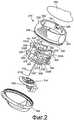
Фиг.2 - вид в перспективе с пространственным разделением деталей известного варианта осуществления сборного установочного устройства, в котором плунжер содержит вводную иглу, прикрепленную к нему,Figure 2 is a perspective view with a spatial separation of the details of a known embodiment of a prefabricated installation device, in which the plunger contains an introduction needle attached to it,
Фиг.3 - вид в перспективе в пяти различных направлениях известного установочного устройства, показанного на фиг.2, с плунжером в выдвинутом положении,Figure 3 is a perspective view in five different directions of the known installation device shown in figure 2, with the plunger in the extended position,
Фиг.4 - вид в перспективе в двух различных направлениях установочного устройства, показанного на фиг.2, с плунжером в отведенном положении,Figure 4 is a perspective view in two different directions of the installation device shown in figure 2, with the plunger in the retracted position,
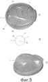
Фиг.5 А, В и С - вид внутренней поверхности и вид внешней поверхности, соответственно, первой части упаковки в соответствии с одним вариантом осуществления изобретения,5A, B and C are a view of the inner surface and a view of the outer surface, respectively, of the first part of the package in accordance with one embodiment of the invention,
Фиг.6 - два вида первой части упаковки в соответствии со вторым вариантом осуществления изобретения,6 is two views of the first part of the package in accordance with the second embodiment of the invention,
Фиг. 7 - трехмерное изображение второго варианта осуществления, показанного на фиг. 6,FIG. 7 is a three-dimensional image of the second embodiment shown in FIG. 6
Фиг.8 - два изображения корпуса установочного устройства в соответствии с изобретением, вид сбоку и вид сверху.Fig - two images of the housing of the installation device in accordance with the invention, side view and top view.
ПОДРОБНОЕ ОПИСАНИЕ ПРЕДПОЧТИТЕЛЬНЫХ ВАРИАНТОВ ОСУЩЕСТВЛЕНИЯDETAILED DESCRIPTION OF THE PREFERRED EMBODIMENTS
На фиг.1 показан пример инфузионного набора 14, подходящего для применения с установочным устройством. Инфузионный набор 14 содержит корпус 3 с внутренней камерой (не показанной). Внутренняя камера получает лекарственное средство по инфузионной трубке 113, которая может быть разъемно присоединена к корпусу 3 подходящим соединителем 7. Опорная деталь 24 корпуса 3 может быть гибким листом тканого материала, закрепленным к корпусу 3, например, адгезивом и содержащим адгезив, закрытый снимаемым листом 14', который снимают для обнажения адгезива перед установкой инфузионного набора. Инфузионный набор 14 содержит выступающую мягкую и гибкую канюлю 26, которая сообщается с внутренней камерой. Внутренний канал, который герметично закрыт уплотняющей мембраной 4 и через который вставляют вводную иглу установочного устройства, продолжается сквозь корпус противоположно канюле 26.Figure 1 shows an example of an infusion set 14, suitable for use with the installation device. The infusion set 14 comprises a
На фиг.2 показан вид в перспективе с пространственным разделением деталей известного варианта осуществления сборного установочного устройства.Figure 2 shows a perspective view with a spatial separation of the details of a known embodiment of a prefabricated installation device.
На фиг.3 и 4 показан тот же самый вариант осуществления в разных видах и положениях.Figures 3 and 4 show the same embodiment in different views and positions.
Упаковка установочного устройства 310 содержит корпус 328 и соответствующие съемные крышки 342, 394. Крышка 342 содержит нишу для вмещения части вводной иглы 312, когда крышка 342 закреплена на корпусе 328, например, сцеплением защелкиванием на закраине 309 корпуса 328. Крышка 342, корпус 328, плунжер 330 и привод с пружиной для выдвижения плунжера 330 в выдвинутое положение могут быть выполнены из пластиков, тогда как крышка 394 может быть гибкой фольгой, зафиксированной на корпусе 328 адгезивом. В предпочтительном варианте, крышки 342, 394 служат антибактериальными барьерами, при этом гибкая фольга 394 выполнена из медицинской бумаги. Вводная игла 312 предпочтительно жестко прикреплена к плунжеру 330 установочного устройства, например, по тугой посадке, при этом плунжер 330 имеет узкий центральный канал, в который помещается конец вводной иглы 112. Плунжер 330 и привод могут быть выполнены неразъемно в одно целое по технологии формования.The packaging of the
Кольцевой корпус 328 является гибким в том смысле, что приложение рукой усилия к диаметрально противоположным углублениям 303 с размерами под кончик пальца будет вызывать слабую деформацию корпуса 328, так что корпус примет немного овальную форму, при наблюдении сверху, для осуществления высвобождения плунжера в отведенном положении, и приведет к перемещению плунжера 330 пружиной к выдвинутому положению, как поясняется далее. Для поддерживания плунжера 330 в отведенном положении корпус 328 снабжен двумя противоположными полками 366. Кроме того, корпус 328 снабжен противолежащими выступами 301 типа «ласточкин хвост», продолжающимися вдоль того же общего направления, что и вводная игла 312, и выполненными с возможностью соединения с ответными выемками в вышеупомянутой пружине, чтобы фиксировать пружину относительно корпуса 328.The
Плунжер 330, в общем, содержит наконечник 332, втулку 331 и, напротив наконечника 332, расширенный захватный участок 331', который позволяет пользователю вытягивать рукой плунжер 330 в отведенное положение. Наконечник 332 обычно содержит маркировку М, обозначающую место, где трубка 113 выходит из инфузионного набора 314, расположенного под наконечником, благодаря чему пользователь может контролировать ориентацию трубки после установки инфузионного набора. Кроме того, наконечник 332 содержит выемку 332' для вмещения инфузионного набора 326 с канюлей 326, через которую продолжается вводная игла 312, при этом инфузионный набор 314 предпочтительно удерживается в заданном положении сцеплением силами трения вводной иглы 312 с внутренней поверхностью инфузионного набора 314. Плунжер 330 содержит две противоположные жесткие стенки 306, продолжающиеся радиально наружу из втулки 331. Стенки 306 продолжаются в аксиальном направлении устройства 310, т.е. в том же общем направлении, что и вводная игла 312, и соединены с вышеупомянутой пружиной. Кроме того, как лучше всего видно на фиг. 3, стенки 306 содержат, каждая, боковой выступ 307 с пальцем 358, который фиксируется с возможностью деблокирования в зацеплении с соответствующей одной из полок 366 корпуса 328 путем защелкивания в отведенном положении плунжера 330. Углубления 303, предпочтительно смещенные относительно полок 366 на приблизительно 90°, будут вынуждать противоположные полки 366 раздвигаться, когда рукой прилагается вышеупомянутое усилие, и корпус 328 принимает овальную форму, что выводит палец 358 на каждой стенке 306 из зацепления с соответствующей полкой 366. Для удерживания проксимальной части трубки 113 (не показанной), которая намотана на плунжер 330, стенка 306 содержит прорезь, выполненную в размер для вмещения небольшого отрезка трубки 113 и для предотвращения случайного отрыва инфузионного набора 314 с плунжера 330 пользователем, когда трубку разматывают для соединения с источником лечебной жидкости.The
Привод, который выполняет функцию приведения плунжера 330 в движение из отведенного положения к выдвинутому положению, когда пальцы 358 расцепляются, содержит пружину, содержащую четыре тонкие и гибкие пластиковые пластинки, из которых две противоположные пластинки 336А продолжаются, приблизительно, вдоль половины окружности вокруг плунжера 330 на уровне захватного участка 331', тогда как две другие противоположные пластинки 336В продолжаются, приблизительно, вдоль половины окружности вокруг плунжера 330 на уровне наконечника 332, при наблюдении в выдвинутом и неподжатом положении плунжера, показанном на фиг. 2 и 3. Один конец 336' одной из пластинок 336А и один конец 336' одной из пластинок 336В жестко соединен с одной из стенок 306, тогда как один конец 336' другой из пластинок 336А и один конец 336' другой из пластинок 336В жестко соединен с другой из стенок 306. В предпочтительном варианте, пластинки 336А и 336В соединены со стенками 306 неразъемно по технологии формования, по которой плунжер 330 и пружина, образованная пластинками 336А и 336В, формуются за одну операцию формования.The actuator, which performs the function of bringing the
Пружина содержит также две жесткие противоположные стенки 302, которые продолжаются в осевом направлении устройства 310, и которые, каждая, жестко соединены со вторым концом 336'' одной из пластинок 336А и вторым концом 336'' одной из других пластинок 336В. Жесткие стенки 302 предпочтительно неразъемно соединены с пластинками 336А и 336В на их втором конце. Жесткие стенки 302 содержат, каждая, аксиально продолжающуюся выемку 305, которая является ответной выступу 301 типа «ласточкин хвост» на корпусе 328. Когда плунжер 330 с пружиной устанавливают внутри корпуса 328, выступ 301 типа «ласточкин хвост» вдвигают в выемку 305 аксиальным перемещением; причем при выборе надлежащих размеров выступа 301 типа «ласточкин хвост» и, возможно также, при выполнении этой операции при заданной температуре может создаваться тугая посадка, которая предотвращает последующее отделение плунжера 330. В качестве альтернативы или дополнительно, плунжер 330 можно закреплять с помощью клея или с использованием сварочного процесса. Две жесткие стенки 302 пружины содержат также соответствующий выступ 308 с нижней поверхностью, которая, в выдвинутом положении плунжера 330, по существу, находится в одной плоскости с закраиной 309 корпуса 328. Выступы 308 содержат фиксатор С зажимного типа для закрепления дистальной части трубки 113, намотанной на плунжер 330, и, тем самым, для удерживания трубки на месте до разматывания пользователем.The spring also contains two rigid
Следует понимать, что стенки 302 зафиксированы относительно корпуса 328, и пластинки 336А и 336В, будучи тонкими и гибкими, образуют части пружины, которые претерпевают изменение формы при отведении плунжера 330 и которые из-за такого изменения формы создают усилие, действующее на плунжер 330 через соединения на концах 336' и необходимое для выдвижения плунжера 330 в выдвинутое положение после отцепления пальцев 358. Форма пластинок 336А и 336В в деформированном состоянии, когда плунжер 330 зафиксирован в отведенном положении, показана на фиг. 4. Соединение между пластинками 336А, 336В и стенками 302, 306, являющееся жестким в том смысле, что изгибающие моменты, возникающие в пластинках 336А, 336В после отведения плунжера 330, передаются стенкам 302, 306, вызывает показанную деформацию пластинок 336А, 336В.It should be understood that the
Следует понимать, что упругость пружины, в общем, определяется упругими свойствами гибких пластинок 336А, 336В, которые следует подбирать так, чтобы привод был способен выдвинуть плунжер 330 в выдвинутое положение, по меньшей мере, один раз после отведения. Пружина обычно должна допускать неоднократное отведение плунжера и обеспечивать необходимое усилие для последующего выдвижения плунжера 330. Однако устройство, представляющее собой обычно одноразовый узел, требует формирования пружины, способной выдвигать плунжер 330 лишь ограниченное число раз с одной заданной скоростью, и от пружины не требуется возврата плунжера в точное исходное положение после нескольких раз использования.It should be understood that the elasticity of the spring, in General, is determined by the elastic properties of the
Как лучше всего видно на фиг.2, две пластинки 336В содержат, каждая, ограждающий элемент 304, который создает опору для трубки (не показанной), соединенной с инфузионным набором 314 и намотанной на плунжер 330 в кольцевом пространстве 315 между плунжером 330 и корпусом 328.As best seen in FIG. 2, the two
В настоящем варианте осуществления корпус 328 образует упаковку и из этого следует, что трубка 113 должна быть намотана с внутренней стороны корпуса 328, чтобы трубка защищалась упаковкой.In the present embodiment, the
На фиг.5А представлен вариант осуществления первой части 1 упаковки в соответствии с изобретением, при наблюдении со стороны, смежной с вводной иглой, при этом данный вариант осуществления содержит одно укладочное место 9а, которое изолирует вводную иглу, и одно укладочное место для принадлежностей 9b. В данном варианте осуществления первая часть 1 заменяет съемную крышку 342 известного установочного устройства и вторая часть образована корпусом 328 и второй съемной крышкой 394. Крышка 342 выполнена из сравнительно твердого материала и содержит нишу для вмещения вводной иглы 312, когда крышка 342 прикреплена к корпусу 328, то крышка предназначена только для защиты вводной иглы 312 от ударов и воздействий, исходящих извне упаковки. Для защиты чувствительной к воздействиям вводной иглы 312 от воздействий, исходящих изнутри упаковки, например, воздействий на комбинированную установочную систему со стороны принадлежностей, уложенных без закрепления в стерильное укладочное место около вводной иглы 312, первая часть 1 снабжена футляром 8 для иглы, продолжающимся от внутренней поверхности 7 первой части 1 и полностью окружающим вводную иглу 312. В данном варианте осуществления второе укладочное место 9b, которое изолировано от вводной иглы 312, имеет форму кольцевой обоймы с незанятым круглым центром, в котором помещается вводная игла 312, 26, когда первую часть 1 упаковки соединяют с установочным устройством 310. Второй вариант показан на Фиг.5В, где футляр 8 для иглы имеет форму стенки, соединенной в двух местах с внутренней поверхностью 7 первой части 1 упаковки.FIG. 5A shows an embodiment of a
Футляр 8 для иглы предпочтительно выполнен из сплошного листа материала, обеспечивающего сплошную защитную стенку для вводной иглы 312, однако, футляр 8 для иглы может быть также выполнен из материала, отличающегося от первой части 1 упаковки, и футляр 8 для иглы может быть также выполнен в виде прерывистой стенки, например выполнен из вертикально установленных стоек или чего-то подобного, что создает прерывистую. стенку, однако, даже прерывистая стенка продолжает защищать вводную иглу 312 от узла или узлов, помещенных между внутренними стенками 7 первой части 1 упаковки и вводной иглой 312, если проемы в футляре 8 для иглы являются достаточно малыми для предотвращения контакта между незакрепленными узлами/принадлежностями и вводной иглой 312.The
На фиг.5С показана первая часть 1 упаковки, при наблюдении с внешней стороны, т.е. нестерильной стороны упаковки.On figs shows the
На фиг.6 показаны два вида варианта выполнения первой части 1 упаковки в соответствии с изобретением, вид сбоку и вид с нестерильной стороны первой части. При этом первая часть 1 упаковки состоит из закраины 2d и профилированной ниши, содержащей нижнюю часть 2а, 2b и ограждающую часть 2с с внутренней поверхностью 7. Чтобы обеспечить упаковку с соответствующей жесткостью, нижняя часть предпочтительно образована с множеством заглубленных 2а и приподнятых 2b областей. На фиг.6 показана нижняя часть, снабженная четырьмя нишами 2а, образующими крестообразную приподнятую часть 2b. Приподнятая часть 2b продолжается по линии А-А по линиям С1-В с обеих сторон закраины 2d.FIG. 6 shows two views of an embodiment of the
Первая часть 1 упаковки закрывает сторону канюли установочного устройства 310, 310' внутри упаковки и выполнена из относительно твердого материала, например полипропилена (РР) или полиэтилена (РЕ), или другого материала, который нельзя проколоть вводной иглой. Относительно твердый материал будет защищать вводную иглу от воздействий окружающей среды, а также окружающая среда будет защищена от вводной иглы 312. Вводная игла может быть либо остроконечной иглой 312, неразъемно соединенной с установочным устройством 310, 310', либо может быть канюлей 26, 326 инфузионного набора 14, когда канюля изготовлена из твердого материала. Вторая часть упаковки (не показанная) в настоящем варианте осуществления закрывает отверстие первой части 1 упаковки, причем отверстие сформировано закраиной 2d и повернуто от вводной иглы 312, 26. Это означает, что вторая часть упаковки не должна защищать вводную иглу и может быть выполнена из мягкого материала, который, например, приклеен или приварен к закраине 2d первой части 1 упаковки.The
При наблюдении со стороны закраины, которая будет также называться верхней частью, упаковка в данном варианте осуществления имеет форму двух частичных окружностей с разными диаметрами D1 и D2. Две частичные окружности превосходят половины от их полных размеров, и это означает, что линия В-В, по которой они пересекаются, определяет сужение формы, образованной закраиной 2d. Независимо от форм, которые могут иметь две секции, целесообразно обеспечить пространство, сформированное стенками 2с с сужением сечения, обозначенным линией (В-В) на фиг.6. Центр большей частичной окружности обозначен С1 и центр меньшей частичной окружности обозначен С2 и положение, в котором линия В-В пересекает линию А-А, обозначено О. Линия В-В в данном варианте осуществления всегда перпендикулярна линии А-А и будет пересекать линию А-А в положении между двумя центрами, обозначенными С1 и С2. Расстояние D между двумя центрами, обозначенными С1 и С2, обозначено на фигуре как dC1-O-C2.When viewed from the side of the flange, which will also be called the upper part, the package in this embodiment has the shape of two partial circles with different diameters D1 and D2. Two partial circles exceed half of their full dimensions, and this means that the line BB, along which they intersect, determines the narrowing of the shape formed by the
В данном варианте осуществления расстояние между внутренними поверхностями стенок 2с по линии В-В является почти таким же, как внешний диаметр корпуса 328 установочного устройства 310, 310', и, предпочтительно, расстояние между внутренними поверхностями стенок 2с по линии В-В немного меньше, чем корпус 328 установочного устройства, и стенки 2с обладают некоторой гибкостью, которая дает возможность протолкнуть корпус 328 установочного устройства 310, 310' из круглой части с большим диаметром в круглую часть с меньшим диаметром и затем зафиксировать установочное устройство 310, 310' в этом положении, поскольку гибкость стенок 2с упаковки не допустит выскальзывания установочного устройства обратно в круглую часть с большим диаметром.In this embodiment, the distance between the inner surfaces of the
В предпочтительном варианте осуществления устройство имеет следующие размеры:In a preferred embodiment, the device has the following dimensions:
Внешний радиус корпуса 328 с направляющим средством 5=57 ммThe outer radius of the
Внешний радиус корпуса 328 без направляющего средства 5=55 ммThe outer radius of the
dC1-B=R1=30,2 ммdC1-B = R1 = 30.2 mm
dC2-B=R2=27, 7 ммdC2-B = R2 = 27.7 mm
D=dC1-O-C2=20,0 ммD = dC1-O-C2 = 20.0 mm
dC1-O=13,74 ммdC1-O = 13.74 mm

⇒ dB-B=2·dB-O=53,77 мм (расстояние между внутренними стенками по линии В-В)⇒ dBB = 2 · dBO = 53.77 mm (the distance between the inner walls along the lineBB )
Первая часть 1 упаковки может быть снабжена средством для фиксации установочного устройства 310, 310' к упаковке внутри круглой части с меньшим диаметром. Такую фиксацию можно осуществить просто продолжением закраины 2d круглой части с меньшим диаметром либо частично, т.е. формированием выступов, продолжающихся внутрь от закраины 2d к центру С2, либо в целом, т.е. продолжением всей закраины к центру С2, с уменьшением, тем самым, диаметра частично круглой части на уровне закраины 2d. Наиболее подходящее решение должно зависеть от материала, используемого для изготовления первой части 1 упаковки и закраины 2d упаковки, причем, обычно, чем более жестким и прочным является материал, тем меньше выступов или меньшая область выступа потребуется для удерживания установочного устройства внутри упаковки.The
Высота Н, представляющая общую высоту первой части 1 упаковки, содержащей как стенки 2с, так и нижнюю часть 2а, 2b должна быть достаточно глубокой для окружения и защиты вводной иглы.The height H representing the total height of the
Область упаковки, расположенная ближе всего к вводной игле и обращенная к ней, в данном варианте осуществления, центральная часть упаковки по линии А-А, будет иметь высоту Н, достаточную для вмещения и защиты вводной иглы, независимо от того расположено ли установочное устройство внутри частичной окружности с наименьшим или наибольшим диаметром.The packing area closest to the insertion needle and facing it, in this embodiment, the central part of the package along line AA, will have a height H sufficient to accommodate and protect the insertion needle, regardless of whether the positioning device is located inside the partial circles with the smallest or largest diameter.
На фиг.6 представлено трехмерное изображение варианта осуществления, показанного на фиг.5.Figure 6 presents a three-dimensional image of the embodiment shown in figure 5.
На фиг.7 показан вариант осуществления установочного устройства, которое можно упаковать в упаковку согласно варианту осуществления, описанному на фиг.5 и 6. В данном варианте осуществления на внешней поверхности 6 корпуса 328 находятся направляющие средства 5.7 shows an embodiment of an installation device that can be packaged in a package according to the embodiment described in FIGS. 5 and 6. In this embodiment, guide means 5 are located on the
Фиг.8 показывает корпус установочного устройства, который может быть использован с изобретением. Аналогично известному устройству, показанному на фиг.2-4, установочное устройство 310' содержит кольцеобразный корпус 328, который является гибким в том смысле, что приложение рукой усилия к диаметрально противоположным углублениям 303 с размерами под кончик пальца (показано только одно углубление) будет вызывать слабую деформацию корпуса 328, так что корпус примет немного овальную форму, при наблюдении сверху, для осуществления высвобождения плунжера в отведенном положении, и приведет к перемещению плунжера пружиной к выдвинутому положению. Для поддерживания плунжера в отведенном положении корпус 328 снабжен двумя противоположными полками 366. Корпус 328 снабжен также противолежащими выступами 301 типа «ласточкин хвост», продолжающимися вдоль того же общего направления, что и вводная игла, и выполненными с возможностью соединения с ответными выемками в пружине, чтобы фиксировать пружину относительно корпуса 328. Плунжер может быть таким, как описано выше и показано на фиг.2, 3 и 4.Fig. 8 shows a housing of an installation device that can be used with the invention. Similarly to the known device shown in FIGS. 2-4, the mounting
Так как упаковка будет изолировать установочное устройство 310' от окружающей среды, то необязательно хранить трубку 113 внутри корпуса 328 до использования, и установочное устройство снабжено горизонтальными фланцами 5, которые могут держать свернутую трубку 113 на месте, когда установочное устройство укладывают внутрь упаковки.Since the package will isolate the
Перед использованием и во время хранения установочное устройство 310' хранится внутри упаковки, при этом сторона иглы/канюли установочного устройства 310' повернута к первой части упаковки, и вторая часть упаковки прикреплена к закраине 2d первой части упаковки,, чтобы обеспечивать воздухонепроницаемое закупоривание стерильной упаковки. Установочное устройство 310' расположено в круглой части с большим диаметром и центром С1, трубка 113 намотана на установочное устройство 310' и вставлена между фланцами 5, соединитель (не показанный), который неразъемно прикреплен к трубке 113 и который может соединять трубку, например, с насосом и/или резервуаром для лекарственного средства, расположен в круглой части с меньшим диаметром.Before use and during storage, the installation device 310 'is stored inside the package, with the needle / cannula side of the installation device 310' turned to the first part of the package and the second part of the package attached to the
Когда пользователь намерен ввести инфузионный набор 14 в кожу, выполняются следующие этапы:When the user intends to introduce the infusion set 14 into the skin, the following steps are performed:
I. Вторая часть упаковки снимается.I. The second part of the packaging is removed.
В предпочтительном варианте вторая часть (не показанная) упаковки имеет форму гибкой мембраны, выполненной, например, из бумаги или пластика, склеенных или отформованных с закраиной 2d первой части 1 упаковки.In a preferred embodiment, the second part (not shown) of the package is in the form of a flexible membrane made, for example, of paper or plastic, glued or molded with a
II. Пользователь захватывает соединитель, расположенный в круглой части с меньшим диаметром, разматывает трубку 113, которая намотана на установочное устройство 310', и присоединяет трубку 113 к устройству, которое может подавать жидкость по трубке 113, например к насосу в комбинации с резервуаром.II. A user grips a connector located in a circular part with a smaller diameter, unwinds the
III. После разматывания трубки 113 пользователю будет несложно поднять установочное устройство 310' из первой части 1 упаковки, привести плунжер в отведенное положение, поместить установочное устройство 310' на кожу и нажать на диаметрально противоположные углубления 303 и, тем самым, вынудить плунжер сдвинуться в переднее положение и поставить инфузионный набор 14. Инфузионный набор 14 оставляют поставленным на коже пациента, а установленное устройство 310' снимают.III. After unwinding the
IV. После использования установочное устройство 310' снова помещают в первую часть 1 упаковки в круглую часть с большим диаметром и из нее установочное устройство 310' проталкивают в круглую часть с меньшим диаметром. В предпочтительном варианте круглая часть с меньшим диаметром снабжена средством для фиксации установочного устройства внутри первой части 1 упаковки, что дает возможность утилизации установочного устройства после использования, без заботы о том, как защитить окружающую среду от воздействия со стороны инфицированной иглы установочного устройства 310'.IV. After use, the installation device 310 'is again placed in the
Чтобы создать возможность для помещения установочного устройства 310' внутрь первой части упаковки, необходимо, чтобы внешний размер установочного устройства, предпочтительно, внешний размер установочного устройства 310' с трубкой 113, намотанной на него, был меньше, чем внутренний размер, по меньшей мере, части первой части 1 упаковки, предпочтительно, внутреннего размера круглой части с большим диаметром.In order to make it possible to place the installation device 310 'inside the first part of the package, it is necessary that the external size of the installation device, preferably the external size of the installation device 310' with the
Чтобы закрепить установочное устройство 310' внутри упаковки после использования, по меньшей мере, часть упаковки снабжена суженым местом. В одном варианте осуществления такое суженое место частично выполнено в виде круглой части с меньшим диаметром и центром С2. Сужение может быть выполнено в виде комбинации из уменьшенного сечения, например, сформированного по линии В-В и, по меньшей мере, одного выступа, продолжающегося внутрь на уровне закраины.To fix the installation device 310 'inside the package after use, at least part of the package is provided with a narrowed space. In one embodiment, such a narrowed place is partially made in the form of a circular part with a smaller diameter and center C2. The narrowing can be made in the form of a combination of a reduced section, for example, formed along the line BB and at least one protrusion, continuing inward at the level of the flange.
Claims (14)
Translated fromRussian- первую часть (1), обеспечивающую дополнительное укладочное место (9b), изолированное от вводной иглы (312, 26), причем первая часть образована нижней частью (2а, 2b) и стенками (2с), расположенными вертикально к нижней части (2а, 2b), и
- вторую часть, которая соединена с первой частью (1) до использования так, что условия внутри упаковки остаются стерильными,
отличающаяся тем, что при наблюдении в сечении по стенкам (2с) стенки (2с) формируют, по меньшей мере, две секции, имеющих, каждая, форму частичного круга с, по меньшей мере, двумя центрами С1 и С2, и центры С1 и С2 различаются и расположены на расстоянии D между ними, что обеспечивает установочному устройству возможность занимать, по меньшей мере, два положения внутри упаковки.1. A package inside which in sterile conditions it is possible to hold the installation device in combination with an infusion set and an injection needle, the package providing a first packing space accommodating the installation device in combination with an infusion set and an injection needle, and contains
- the first part (1), providing an additional laying place (9b), isolated from the insertion needle (312, 26), the first part being formed by the lower part (2a, 2b) and walls (2c) located vertically to the lower part (2a, 2b), and
- the second part, which is connected to the first part (1) before use so that the conditions inside the package remain sterile,
characterized in that, when observed in a section along the walls (2c) of the wall (2c), at least two sections are formed, each having a partial circle shape with at least two centers C1 and C2, and centers C1 and C2 differ and are located at a distance D between them, which allows the installation device to occupy at least two positions inside the package.
Applications Claiming Priority (4)
| Application Number | Priority Date | Filing Date | Title |
|---|---|---|---|
| US77280706P | 2006-02-13 | 2006-02-13 | |
| DKPA200600205 | 2006-02-13 | ||
| US60/772,807 | 2006-02-13 | ||
| DKPA200600205 | 2006-02-13 |
Publications (2)
| Publication Number | Publication Date |
|---|---|
| RU2008136872A RU2008136872A (en) | 2010-03-20 |
| RU2426515C2true RU2426515C2 (en) | 2011-08-20 |
Family
ID=37963848
Family Applications (1)
| Application Number | Title | Priority Date | Filing Date |
|---|---|---|---|
| RU2008136872/14ARU2426515C2 (en) | 2006-02-13 | 2007-02-13 | Package for installation device |
Country Status (10)
| Country | Link |
|---|---|
| US (1) | US20090218243A1 (en) |
| EP (1) | EP1988949A2 (en) |
| KR (1) | KR20080110586A (en) |
| CN (1) | CN101384287B (en) |
| AU (1) | AU2007214859B2 (en) |
| CA (1) | CA2642440A1 (en) |
| MX (1) | MX2008010286A (en) |
| NO (1) | NO20083884L (en) |
| RU (1) | RU2426515C2 (en) |
| WO (1) | WO2007093182A2 (en) |
Families Citing this family (48)
| Publication number | Priority date | Publication date | Assignee | Title |
|---|---|---|---|---|
| MXPA06010784A (en) | 2004-03-26 | 2006-12-15 | Unomedical As | Injector device for infusion set. |
| US8062250B2 (en) | 2004-08-10 | 2011-11-22 | Unomedical A/S | Cannula device |
| US7985199B2 (en) | 2005-03-17 | 2011-07-26 | Unomedical A/S | Gateway system |
| EP1762259B2 (en) | 2005-09-12 | 2025-01-01 | Unomedical A/S | Inserter for an infusion set with a first and second spring units |
| DK1962926T3 (en) | 2005-12-23 | 2009-09-28 | Unomedical As | injection device |
| WO2007098771A2 (en) | 2006-02-28 | 2007-09-07 | Unomedical A/S | Inserter for infusion part and infusion part provided with needle protector |
| CA2653631A1 (en) | 2006-06-07 | 2007-12-13 | Unomedical A/S | Inserter |
| CA2653764A1 (en) | 2006-06-09 | 2007-12-13 | Unomedical A/S | Mounting pad |
| JP2009545341A (en) | 2006-08-02 | 2009-12-24 | ウノメディカル アクティーゼルスカブ | Cannula and delivery device |
| EP2155311B1 (en) | 2007-06-20 | 2013-01-02 | Unomedical A/S | A method and an apparatus for making a catheter |
| AU2008270327A1 (en) | 2007-07-03 | 2009-01-08 | Unomedical A/S | Inserter having bistable equilibrium states |
| DE602008005153D1 (en) | 2007-07-10 | 2011-04-07 | Unomedical As | INSERT WITH TWO SPRINGS |
| AU2008277763B2 (en) | 2007-07-18 | 2011-11-10 | Unomedical A/S | Insertion device with pivoting action |
| EP2200677A1 (en) | 2007-09-17 | 2010-06-30 | ICU Medical, Inc. | Insertion devices for infusion devices |
| ATE522240T1 (en) | 2008-02-13 | 2011-09-15 | Unomedical As | SEAL BETWEEN A CANNULAR PART AND A FLUID PATH |
| US9566384B2 (en) | 2008-02-20 | 2017-02-14 | Unomedical A/S | Insertion device with horizontally moving part |
| BRPI0919548A2 (en)* | 2008-09-29 | 2015-12-08 | Unomedical As | insert package |
| AU2009331635A1 (en) | 2008-12-22 | 2011-06-23 | Unomedical A/S | Medical device comprising adhesive pad |
| CA2749528C (en) | 2009-01-21 | 2020-08-18 | Becton, Dickinson And Company | Infusion set |
| AU2010277755A1 (en) | 2009-07-30 | 2012-02-02 | Unomedical A/S | Inserter device with horizontal moving part |
| KR20120047896A (en) | 2009-08-07 | 2012-05-14 | 우노메디컬 에이/에스 | Delivery device with sensor and one or more cannulas |
| KR20130018783A (en) | 2010-03-30 | 2013-02-25 | 우노메디컬 에이/에스 | Medical device |
| EP2433663A1 (en) | 2010-09-27 | 2012-03-28 | Unomedical A/S | Insertion system |
| EP2436412A1 (en) | 2010-10-04 | 2012-04-04 | Unomedical A/S | A sprinkler cannula |
| US10046106B2 (en) | 2010-10-25 | 2018-08-14 | Bayer Healthcare Llc | Bladder syringe fluid delivery system |
| US9498570B2 (en) | 2010-10-25 | 2016-11-22 | Bayer Healthcare Llc | Bladder syringe fluid delivery system |
| WO2012123274A1 (en) | 2011-03-14 | 2012-09-20 | Unomedical A/S | Inserter system with transport protection |
| PL2510914T3 (en)* | 2011-04-12 | 2015-02-27 | Hoffmann La Roche | Connector device |
| WO2013050277A1 (en) | 2011-10-05 | 2013-04-11 | Unomedical A/S | Inserter for simultaneous insertion of multiple transcutaneous parts |
| EP2583715A1 (en) | 2011-10-19 | 2013-04-24 | Unomedical A/S | Infusion tube system and method for manufacture |
| US9440051B2 (en) | 2011-10-27 | 2016-09-13 | Unomedical A/S | Inserter for a multiplicity of subcutaneous parts |
| US9180252B2 (en) | 2012-04-20 | 2015-11-10 | Bayer Medical Care Inc. | Bellows syringe fluid delivery system |
| USD709767S1 (en) | 2013-03-14 | 2014-07-29 | Becton, Dickinson And Company | Package portion for a medical product |
| US9943641B2 (en) | 2013-03-14 | 2018-04-17 | Becton, Dickinson And Company | Package for medical product |
| US9814871B2 (en) | 2013-03-15 | 2017-11-14 | Bayer Healthcare Llc | Connector assembly for syringe system |
| USD824530S1 (en)* | 2015-07-01 | 2018-07-31 | Fluisense Aps | Blood collecting device |
| AU2016359665B2 (en) | 2015-11-25 | 2021-11-04 | Bayer Healthcare Llc | Syringe and connector system |
| EP3539596A1 (en)* | 2018-03-15 | 2019-09-18 | Tecpharma Licensing AG | An assembly for an injection or infusion device |
| CR20220394A (en) | 2020-02-21 | 2023-01-23 | Bayer Healthcare Llc | Fluid path connectors for medical fluid delivery |
| PT4110452T (en) | 2020-02-28 | 2025-01-14 | Bayer Healthcare Llc | FLUID MIXING SET |
| WO2021188460A1 (en) | 2020-03-16 | 2021-09-23 | Bayer Healthcare Llc | Stopcock apparatus for angiography injector fluid paths |
| CN115697435A (en) | 2020-06-18 | 2023-02-03 | 拜耳医药保健有限责任公司 | Inline Bubble Suspension Device for the Fluid Path of Angiography Injectors |
| RS66861B1 (en) | 2020-08-11 | 2025-06-30 | Bayer Healthcare Llc | Features for angiography syringe |
| CN116547022A (en) | 2020-12-01 | 2023-08-04 | 拜耳医药保健有限责任公司 | Cassette for holding fluid path components of a fluid injector system |
| WO2022265695A1 (en) | 2021-06-17 | 2022-12-22 | Bayer Healthcare Llc | System and method for detecting fluid type in tubing for fluid injector apparatus |
| USD1043976S1 (en) | 2022-08-26 | 2024-09-24 | Deka Products Limited Partnership | Fluid transfer connector |
| USD1090862S1 (en) | 2022-08-26 | 2025-08-26 | Deka Products Limited Partnership | Adhering assembly for medical devices and the like |
| USD1057941S1 (en) | 2022-08-26 | 2025-01-14 | Deka Products Limited Partnership | Patient care assembly component |
Citations (4)
| Publication number | Priority date | Publication date | Assignee | Title |
|---|---|---|---|---|
| US5379895A (en)* | 1993-09-13 | 1995-01-10 | Minnesota Mining And Manufacturing Company | Package for surgical device |
| EP0739638A1 (en)* | 1994-08-19 | 1996-10-30 | Eiken Chemical Co., Ltd. | Method of sterilizing prefilled syringe medicines |
| WO2004056412A2 (en)* | 2002-12-23 | 2004-07-08 | M2 Medical A/S | A disposable, wearable insulin dispensing device, a combination of such a device and a programming controller and a method of controlling the operation of such a device |
| US20050283114A1 (en)* | 2004-06-16 | 2005-12-22 | Timothy Bresina | Device and method for insertion of a cannula of an infusion device |
Family Cites Families (96)
| Publication number | Priority date | Publication date | Assignee | Title |
|---|---|---|---|---|
| US2972779A (en)* | 1954-06-07 | 1961-02-28 | Baxter Don Inc | Plastic tubing process |
| US3074541A (en)* | 1959-10-13 | 1963-01-22 | Brunswick Corp | Medicinal vial and needle assembly |
| US3306291A (en)* | 1964-04-14 | 1967-02-28 | Burron Medical Prod Inc | Disposable sterile syringes, needle containers and the like having prestressed frangible portions therein |
| US3783895A (en)* | 1971-05-04 | 1974-01-08 | Sherwood Medical Ind Inc | Universal parenteral fluid administration connector |
| US3788374A (en)* | 1972-01-26 | 1974-01-29 | Jintan Terumo Co | Parenteral solution bag |
| US3937219A (en)* | 1974-01-14 | 1976-02-10 | Karakashian Nubar A | Sterile syringe assembly and method of making same |
| GB1580924A (en)* | 1977-06-24 | 1980-12-10 | Smiths Industries Ltd | Methods of hole-forming in plastics workpieces and products manufactured using such methods |
| DE2862268D1 (en)* | 1977-08-01 | 1983-07-07 | Roger Sanderson | Sterilized storage container and method |
| US4188950A (en)* | 1978-10-30 | 1980-02-19 | Wardlaw Stephen C | Disposable syringe |
| US4315505A (en)* | 1980-04-07 | 1982-02-16 | Shiley, Inc. | Tracheostomy tube with disposable inner cannula |
| US4378015A (en)* | 1981-12-21 | 1983-03-29 | Wardlaw Stephen C | Automatic injecting syringe |
| US4500312A (en)* | 1982-12-15 | 1985-02-19 | Mcfarlane Richard H | Connecting assembly |
| US4563177A (en)* | 1983-12-22 | 1986-01-07 | Kamen Dean L | Catheter stabilization pad |
| GB2176402B (en)* | 1985-06-20 | 1989-04-19 | Craig Med Prod Ltd | Wound management appliance for use on the human skin |
| US4734092A (en)* | 1987-02-18 | 1988-03-29 | Ivac Corporation | Ambulatory drug delivery device |
| US4895570A (en)* | 1987-06-05 | 1990-01-23 | Abbott Laboratories | Locking port shroud for peritoneal dialysis tubing connector |
| GB8812096D0 (en)* | 1988-05-21 | 1988-06-22 | Smith & Nephew Ass | Adhesive sheet |
| US4894054A (en)* | 1988-06-20 | 1990-01-16 | Miskinyar Shir A | Preloaded automatic disposable syringe |
| US4986817A (en)* | 1988-11-22 | 1991-01-22 | International Development Systems, Inc. | Hypodermic syringe sheath holder and needle guide |
| US5072832A (en)* | 1989-03-09 | 1991-12-17 | Devon Industries, Inc. | Multipurpose shaped pitcher and surgical kit and wrap system |
| US4994042A (en)* | 1989-10-02 | 1991-02-19 | Vadher Dinesh L | Combined catheter and needle |
| US5282793A (en)* | 1989-10-02 | 1994-02-01 | Larson Eldon E | Syringe holder and applicator |
| US5222947A (en)* | 1990-04-18 | 1993-06-29 | Amico Elio D | Self recapping injection needle assembly |
| US4994045A (en)* | 1990-04-20 | 1991-02-19 | Sherwood Medical Company | Split sleeve safety syringe |
| US5188611A (en)* | 1990-05-31 | 1993-02-23 | Orgain Peter A | Safety sheath for needles, sharp instruments and tools |
| US4982842A (en)* | 1990-06-04 | 1991-01-08 | Concord/Portex | Safety needle container |
| US5098389A (en)* | 1990-06-28 | 1992-03-24 | Becton, Dickinson And Company | Hypodermic needle assembly |
| US5279591A (en)* | 1990-07-16 | 1994-01-18 | Simon Alexander Z | Protector for needle catheter |
| US5176662A (en)* | 1990-08-23 | 1993-01-05 | Minimed Technologies, Ltd. | Subcutaneous injection set with improved cannula mounting arrangement |
| GB9100819D0 (en)* | 1991-01-15 | 1991-02-27 | Medimech Int Ltd | Subcutaneous injector |
| US5092853A (en)* | 1991-02-04 | 1992-03-03 | Couvertier Ii Douglas | Automatic retractable medical needle and method |
| US5176643A (en)* | 1991-04-29 | 1993-01-05 | George C. Kramer | System and method for rapid vascular drug delivery |
| US5186712A (en)* | 1991-08-23 | 1993-02-16 | Kansas Creative Devices, Inc. | Intravenous catheter launching device |
| US5176650A (en)* | 1992-02-10 | 1993-01-05 | Haining Michael L | Intravenous catheter and insertion device |
| DK169711B1 (en)* | 1993-01-15 | 1995-01-23 | Coloplast As | A dressing |
| US5545143A (en)* | 1993-01-21 | 1996-08-13 | T. S. I. Medical | Device for subcutaneous medication delivery |
| US5387197A (en)* | 1993-02-25 | 1995-02-07 | Ethicon, Inc. | Trocar safety shield locking mechanism |
| EP0693946B1 (en)* | 1993-03-24 | 2001-05-16 | Owen Mumford Limited | Improvements relating to injection devices |
| US5390669A (en)* | 1993-08-09 | 1995-02-21 | Mallinckrodt Medical, Inc. | Device using connector tube to lock inner cannula inside outer cannula |
| DE4410876A1 (en)* | 1994-03-29 | 1995-10-05 | Fresenius Ag | Medical multi-chamber bag and process for its manufacture |
| IL109294A (en)* | 1994-04-12 | 1998-02-08 | Wais Med Ltd | Surgical instrument for impact insertion of an intraosseous trocar- needle |
| US5490841A (en)* | 1994-07-29 | 1996-02-13 | Landis; Robert M. | Safety sheath device |
| US5501675A (en)* | 1994-12-27 | 1996-03-26 | Becton, Dickinson And Company | Safety catheter assembly having safety stop push button |
| US5836917A (en)* | 1995-01-10 | 1998-11-17 | Specialized Health Products, Inc. | Self retracting medical needle apparatus and methods |
| US5599318A (en)* | 1995-08-29 | 1997-02-04 | Becton, Dickinson And Company | Needle shield assembly having a releasable lock |
| US5599315A (en)* | 1995-12-01 | 1997-02-04 | Charles J. McPhee | Syringe actuation device |
| ZA9610374B (en)* | 1995-12-11 | 1997-06-23 | Elan Med Tech | Cartridge-based drug delivery device |
| US5865806A (en)* | 1996-04-04 | 1999-02-02 | Becton Dickinson And Company | One step catheter advancement automatic needle retraction system |
| US5704920A (en)* | 1996-05-17 | 1998-01-06 | Becton, Dickinson And Company | Manually driven needle shield assembly |
| US20070142776A9 (en)* | 1997-02-05 | 2007-06-21 | Medtronic Minimed, Inc. | Insertion device for an insertion set and method of using the same |
| US6607509B2 (en)* | 1997-12-31 | 2003-08-19 | Medtronic Minimed, Inc. | Insertion device for an insertion set and method of using the same |
| US6224571B1 (en)* | 1997-11-14 | 2001-05-01 | Venetec International, Inc. | Medical line securement device |
| US6056718A (en)* | 1998-03-04 | 2000-05-02 | Minimed Inc. | Medication infusion set |
| USD421119S (en)* | 1998-04-28 | 2000-02-22 | Becton, Dickinson And Company | Introducer needle |
| US6183464B1 (en)* | 1998-06-01 | 2001-02-06 | Inviro Medical Devices Ltd. | Safety syringe with retractable needle and universal luer coupling |
| US6503231B1 (en)* | 1998-06-10 | 2003-01-07 | Georgia Tech Research Corporation | Microneedle device for transport of molecules across tissue |
| US6355021B1 (en)* | 1998-07-14 | 2002-03-12 | Maersk Medical A/S | Medical puncturing device |
| US6191338B1 (en)* | 1998-11-19 | 2001-02-20 | Kurt Haller | Adhesive bandage, matrix, and methods of removal |
| US6042570A (en)* | 1999-02-11 | 2000-03-28 | Dsu Medical Corporation | Needle point protection sheath |
| US6039629A (en)* | 1999-05-06 | 2000-03-21 | Mitchell; Julia | Nursing pad |
| US6663862B1 (en)* | 1999-06-04 | 2003-12-16 | Duke University | Reagents for detection and purification of antibody fragments |
| US6837877B2 (en)* | 1999-08-23 | 2005-01-04 | Becton, Dickinson And Company | Safety shield assembly |
| US7198618B2 (en)* | 1999-11-04 | 2007-04-03 | Tyco Healthcare Group Lp | Safety shield for medical needles |
| US6517517B1 (en)* | 2000-06-08 | 2003-02-11 | Mayo Foundation For Medical Education And Research | Automated injection device for administration of liquid medicament |
| US6986760B2 (en)* | 2000-08-02 | 2006-01-17 | Becton, Dickinson And Company | Pen needle and safety shield system |
| US6702779B2 (en)* | 2000-08-18 | 2004-03-09 | Becton, Dickinson And Company | Constant rate fluid delivery device with selectable flow rate and titratable bolus button |
| US6503222B2 (en)* | 2000-09-28 | 2003-01-07 | Pfizer Inc | Oral dosage dispenser |
| US6808514B2 (en)* | 2000-10-17 | 2004-10-26 | Patricia G. Schneider | Emergency medical dispensing card |
| ES2281457T3 (en)* | 2000-11-09 | 2007-10-01 | Insulet Corporation | TRANSCUTANEOUS SUPPLY MEDIA. |
| US7083597B2 (en)* | 2001-01-05 | 2006-08-01 | Applied Diabetes Research, Inc. | Pivoting joint infusion system with seal |
| US6837878B2 (en)* | 2001-01-09 | 2005-01-04 | Icu Medical, Inc. | Bluntable needle assembly with open-ended blunting probe |
| IL157561A0 (en)* | 2001-03-04 | 2004-03-28 | Sterling Medivations Inc | Infusion hub assembly and fluid line disconnect system |
| US6994213B2 (en)* | 2001-09-18 | 2006-02-07 | Becton, Dickinson And Company | Packaging for push button blood collection set |
| US6830562B2 (en)* | 2001-09-27 | 2004-12-14 | Unomedical A/S | Injector device for placing a subcutaneous infusion set |
| ITTO20011228A1 (en)* | 2001-12-28 | 2003-06-28 | Cane Srl | DISPOSABLE NEEDLE CONTAINER. |
| US20070005017A1 (en)* | 2002-02-04 | 2007-01-04 | Becton, Dickinson And Company | Intradermal delivery device with crenellated skin engaging surface geometry |
| EP2111885B1 (en)* | 2002-02-04 | 2011-09-21 | Becton, Dickinson and Company | Device and method for delivering or withdrawing a substance through the skin |
| USD472316S1 (en)* | 2002-04-30 | 2003-03-25 | Sterling Medivations, Inc. | Pen needle catheter connector |
| US7338465B2 (en)* | 2002-07-02 | 2008-03-04 | Patton Medical Devices, Lp | Infusion device and method thereof |
| US20040059316A1 (en)* | 2002-07-31 | 2004-03-25 | Smedegaard Jorgen K. | Medical delivery device |
| CN1723053A (en)* | 2002-09-12 | 2006-01-18 | 儿童医院医疗中心 | Method and device for painless drug injection |
| DE10255817A1 (en)* | 2002-11-29 | 2004-06-17 | Disetronic Licensing Ag | Catheter head with lockable sealing element |
| US20040158202A1 (en)* | 2003-02-12 | 2004-08-12 | Soren Jensen | Cover |
| US20060069382A1 (en)* | 2003-04-11 | 2006-03-30 | Novo Nordisk A/S | Delivery device |
| US6926694B2 (en)* | 2003-05-09 | 2005-08-09 | Medsolve Technologies, Llc | Apparatus and method for delivery of therapeutic and/or diagnostic agents |
| WO2004101016A1 (en)* | 2003-05-19 | 2004-11-25 | De Villiers, Malan | Preparation of an osteoinductive agent |
| EP3695862A1 (en)* | 2003-08-12 | 2020-08-19 | Becton, Dickinson and Company | Patch-like infusion device |
| CN100586414C (en)* | 2003-10-21 | 2010-02-03 | 诺沃挪第克公司 | Reservoir device with inclined needle |
| GB2407505A (en)* | 2003-10-24 | 2005-05-04 | Cliniframe Ltd | Container for a sharp instrument |
| CA2549050C (en)* | 2003-12-30 | 2011-03-08 | Disetronic Licensing Ag | Insertion device for infusion sets |
| MXPA06010784A (en)* | 2004-03-26 | 2006-12-15 | Unomedical As | Injector device for infusion set. |
| DK1616594T3 (en)* | 2004-07-15 | 2007-05-29 | Clinico Betr Sverpachtungs Gmb | Puncture device with a flexible, permanent tube for connection to a medical supply line |
| DE202004011617U1 (en)* | 2004-07-23 | 2004-10-07 | Clinico Gmbh | Coupling device for connecting a medical supply line to a catheter |
| US8062250B2 (en)* | 2004-08-10 | 2011-11-22 | Unomedical A/S | Cannula device |
| CA2612664A1 (en)* | 2005-06-28 | 2007-01-04 | Unomedical A/S | Packing for infusion set and method of applying an infusion set |
| CA2659077A1 (en)* | 2006-08-02 | 2008-02-07 | Unomedical A/S | Insertion device |
- 2006
- 2006-02-13USUS12/279,138patent/US20090218243A1/ennot_activeAbandoned
- 2007
- 2007-02-13EPEP07711306Apatent/EP1988949A2/ennot_activeWithdrawn
- 2007-02-13CNCN200780005249XApatent/CN101384287B/ennot_activeExpired - Fee Related
- 2007-02-13WOPCT/DK2007/050018patent/WO2007093182A2/enactiveApplication Filing
- 2007-02-13MXMX2008010286Apatent/MX2008010286A/enactiveIP Right Grant
- 2007-02-13RURU2008136872/14Apatent/RU2426515C2/ennot_activeIP Right Cessation
- 2007-02-13AUAU2007214859Apatent/AU2007214859B2/ennot_activeCeased
- 2007-02-13KRKR1020087020635Apatent/KR20080110586A/ennot_activeCeased
- 2007-02-13CACA002642440Apatent/CA2642440A1/ennot_activeAbandoned
- 2008
- 2008-09-10NONO20083884Apatent/NO20083884L/ennot_activeApplication Discontinuation
Patent Citations (4)
| Publication number | Priority date | Publication date | Assignee | Title |
|---|---|---|---|---|
| US5379895A (en)* | 1993-09-13 | 1995-01-10 | Minnesota Mining And Manufacturing Company | Package for surgical device |
| EP0739638A1 (en)* | 1994-08-19 | 1996-10-30 | Eiken Chemical Co., Ltd. | Method of sterilizing prefilled syringe medicines |
| WO2004056412A2 (en)* | 2002-12-23 | 2004-07-08 | M2 Medical A/S | A disposable, wearable insulin dispensing device, a combination of such a device and a programming controller and a method of controlling the operation of such a device |
| US20050283114A1 (en)* | 2004-06-16 | 2005-12-22 | Timothy Bresina | Device and method for insertion of a cannula of an infusion device |
Also Published As
| Publication number | Publication date |
|---|---|
| AU2007214859B2 (en) | 2010-07-08 |
| EP1988949A2 (en) | 2008-11-12 |
| WO2007093182A3 (en) | 2007-10-18 |
| NO20083884L (en) | 2008-09-10 |
| CN101384287A (en) | 2009-03-11 |
| US20090218243A1 (en) | 2009-09-03 |
| CN101384287B (en) | 2011-11-16 |
| AU2007214859A1 (en) | 2007-08-23 |
| WO2007093182A2 (en) | 2007-08-23 |
| KR20080110586A (en) | 2008-12-18 |
| MX2008010286A (en) | 2009-01-23 |
| RU2008136872A (en) | 2010-03-20 |
| CA2642440A1 (en) | 2007-08-23 |
Similar Documents
| Publication | Publication Date | Title |
|---|---|---|
| RU2426515C2 (en) | Package for installation device | |
| ES2929769T3 (en) | Disinfectant caps for medical connectors | |
| ES2212030T3 (en) | SYRINGE SET. | |
| JP5903485B2 (en) | Connector device | |
| ES2931035T3 (en) | Syringe assembly with flexible or slip-on flange | |
| US5476106A (en) | Method of destroying and storing used cannulas | |
| AU2007280850B9 (en) | Cannula and delivery device | |
| CA2990666C (en) | Outer cover of a pen needle for a drug delivery pen | |
| EP3178504B1 (en) | Package and package assembly | |
| JP6190008B2 (en) | Reversible cap for pen needle outer cover | |
| US11197689B2 (en) | Inserter for simultaneous insertion of multiple transcutaneous parts | |
| JP2016047477A (en) | Single use device for delivery of cartridge drugs | |
| WO2016177856A1 (en) | Sealed packages containing a medical device | |
| CN109475697A (en) | Medical devices including packaging and prefilled syringes placed in the packaging | |
| JP6974905B2 (en) | Pen needle magazine | |
| JP6921117B2 (en) | Pen Needle Magazine | |
| JP6983810B2 (en) | Pen needle magazine | |
| JP5965233B2 (en) | Drug micro-administration device | |
| BR112014027365B1 (en) | Sheath that protects a cannula and a safety syringe system that comprises said sheath |
Legal Events
| Date | Code | Title | Description |
|---|---|---|---|
| MM4A | The patent is invalid due to non-payment of fees | Effective date:20130214 |