RU2426306C1 - Device to treat corneous formations of animals, for instance, cattle - Google Patents
Device to treat corneous formations of animals, for instance, cattleDownload PDFInfo
- Publication number
- RU2426306C1 RU2426306C1RU2010112395/21ARU2010112395ARU2426306C1RU 2426306 C1RU2426306 C1RU 2426306C1RU 2010112395/21 ARU2010112395/21 ARU 2010112395/21ARU 2010112395 ARU2010112395 ARU 2010112395ARU 2426306 C1RU2426306 C1RU 2426306C1
- Authority
- RU
- Russia
- Prior art keywords
- disk
- horn
- guide plate
- support disk
- handle
- Prior art date
Links
- 241001465754MetazoaSpecies0.000titleclaimsdescription8
- 241000283690Bos taurusSpecies0.000titleclaimsdescription4
- 230000015572biosynthetic processEffects0.000titleclaims2
- 238000005755formation reactionMethods0.000titleclaims2
- 239000004744fabricSubstances0.000claimsdescription2
- 238000007664blowingMethods0.000abstract2
- 239000000126substanceSubstances0.000abstract1
- 210000000003hoofAnatomy0.000description8
- 210000003414extremityAnatomy0.000description3
- 230000011164ossificationEffects0.000description3
- 201000010099diseaseDiseases0.000description2
- 208000037265diseases, disorders, signs and symptomsDiseases0.000description2
- 239000003814drugSubstances0.000description2
- 238000000034methodMethods0.000description2
- 230000000399orthopedic effectEffects0.000description2
- 230000002265preventionEffects0.000description2
- 239000007787solidSubstances0.000description2
- 238000009966trimmingMethods0.000description2
- 102220631423Very-long-chain (3R)-3-hydroxyacyl-CoA dehydratase 1_A61D_mutationHuman genes0.000description1
- 244000309464bullSpecies0.000description1
- 238000001816coolingMethods0.000description1
- 230000006378damageEffects0.000description1
- 238000000227grindingMethods0.000description1
- 238000003801millingMethods0.000description1
- 210000000115thoracic cavityAnatomy0.000description1
- 210000003857wrist jointAnatomy0.000description1
Images


Landscapes
- Crushing And Pulverization Processes (AREA)
Abstract
Description
Translated fromRussianПредлагаемое изобретение относится к сельскому хозяйству, ветеринарной медицине, конкретно к устройствам и приспособлениям для удаления излишнего рога копытец и острых концов роговых чехлов.The present invention relates to agriculture, veterinary medicine, specifically to devices and devices for removing excess horn hooves and sharp ends of horn covers.
По авторскому свидетельству СССР №893194 (1) известно устройство для обрезания роговых и костных образований у животных, содержащее электропривод с гибким валом, в панцире соединенным с валом на подшипниках в корпусе, несущем на конце режущий рог аппарат в виде дисковой фрезы, причем между корпусом и режущим аппаратом установлен опорный диск с секторным вырезом, а перед режущим рог аппаратом установлена фигурная направляющая пластина.According to USSR author's certificate No. 893194 (1), a device is known for trimming horn and bone formations in animals, containing an electric drive with a flexible shaft, in a carapace connected to the shaft with bearings in a housing that carries a cutting horn in the form of a disk cutter at the end, and between the housing and a cutting apparatus has a support disk with a sector cut, and a curved guide plate is installed in front of the cutting horn.
По патенту РФ №2375991 (2) известно устройство для профилактики и лечения ортопедических заболеваний у животных, например крупного рогатого скота, имеющее корпус-ручку, в котором размещен электродвигатель с валом, несущим турбину-ветродуйку, а на конце дисковую фрезу, причем турбина-ветродуйка подает поток охлаждающего воздуха на дисковую фрезу и в место разреза роговых и костных образований через выполненные в корпусе-ручке перфорации, при этом на участке корпуса-ручки, прилежащем к дисковой фрезе, имеется резьбовой участок, по которому может перемещаться и фиксироваться в нужном месте контрогайкой резьбовой участок опорного диска.According to the patent of the Russian Federation No. 2375991 (2), a device is known for the prevention and treatment of orthopedic diseases in animals, for example cattle, having a handle housing in which an electric motor with a shaft carrying a wind turbine and a disk cutter at the end, the turbine the wind blower supplies a flow of cooling air to the disk cutter and to the incision site of the horn and bone formations through perforations made in the handle body, while there is a threaded section on the handle body area adjacent to the disk mill Then the threaded section of the support disk can be moved and fixed in the right place with the locknut.
Цель изобретения - повышение удобства и производительности работы оператора, сокращение времени пребывания животного на обработке.The purpose of the invention is to increase the convenience and productivity of the operator, reducing the time spent by the animal on the processing.
Поставленная цель достигается тем, что в передней части корпуса-ручки размещен круговой упор для руки, закрепленная на валу электродвигателя крыльчатка-ветродуйка подает струю воздуха через конической формы каналы в передней стенке корпуса-ручки, к режущим рог копытца частям дисковой фрезы, при этом одна сторона смещаемого и фиксируемого в нужном месте опорного диска удалена и по месту удаления имеет форму, идентичную форме этой же стороны фигурной направляющей пластины.This goal is achieved by the fact that in the front part of the handle body there is a circular palm rest, mounted on the shaft of the electric motor, the wind-wheel impeller delivers a stream of air through the conical shape of the channels in the front wall of the handle body, to the parts of the disk cutter cutting the horn of the hoof, while one the side of the support disk that is displaced and fixed in the right place is removed and at the place of removal has a shape identical to that of the same side of the curly guide plate.
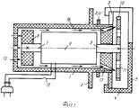
Устройство схематично изображено на фиг.1 в продольном разрезе, на фиг.2 - спереди, на фиг.3 - спереди опорный диск с частями А и В.The device is schematically shown in FIG. 1 in longitudinal section, in FIG. 2 in front, in FIG. 3 in front, a support disk with parts A and B.
Устройство имеет корпус-ручку 1 с круговым упором 2 для смещения руки вперед, смещаемый опорный диск 3 с фиксирующей его в нужном месте контргайкой 3«а», со стойками 4 фигурной направляющей пластины 5.The device has a handle-body 1 with a
Внутри корпуса-ручки 1 находится электродвигатель 6. Его задний вал 7 несет турбину-ветродуйку 8, передний вал 9 - аппарат в виде дисковой фрезы 10 с отверстиями 11 в полотнище и фигурными зубьями на периферии. При этом дисковая фреза (аппарат) расположена между фигурной направляющей пластиной и опорным диском. Позицией 12 обозначены перфорации в корпусе-ручке, 13 - конические каналы в передней ее стенке, 14 - секторные вырезы в фигурной направляющей пластине 5 и опорном диске 3 (фиг.2 и 3), 15 - тумблер электросети, 16 - направление движения потока воздуха, позицией А - сплошная часть опорного диска, В - место после удаления его части.Inside the handle housing 1 is an
Работа устройства: вводят животное в фиксационный станок, дистальную часть, допустим, грудной конечности, согнутой в запястном суставе, неподвижно укрепляют, осматривают копытца, определяют объем и порядок выполнения работы, включают тумблер 15 электрокабеля, присоединенного вилкой к источнику электроэнергии, смещают опорный диск 3 на нужное удаление, фиксируют его в этом положении контргайкой 3«а».The operation of the device: the animal is introduced into the fixation machine, the distal part, for example, of the thoracic extremity, bent at the wrist joint, is fixedly fixed, the hooves are examined, the volume and procedure of the work are determined, the
Если нужно отрезать излишний рог копытцевой стенки на небольшое расстояние, размещают подошвенный край ее на сплошной части А опорного диска 3, перемещая устройство по этой стороне фигурной направляющей пластины, отпиливают вращаемой валом 9 дисковой фрезой 10 излишний рог, в том случае, когда необходимо удалить рог стенки копытца на большую глубину, размещают корпус-ручку 1 так, чтобы подошвенный край ее находился на стороне «В» опорного диска, 3 и отпиливают рог, смещая стенку копытца по направляющей кромке фигурной направляющей пластины 5 и фигурной кромке опорного диска 3. При этом к вращаемой валом 7 электродвигателя 6 крыльчатке-ветродуйке 8 воздух поступает через отверстия 12 в задней стенке корпуса-ручки 1, скоростной поток его по направлению, указанному стрелкой 16, подается через узкие отверстия наклонных конической формы каналов 13 непосредственно к режущим рог частям дисковой фрезы 10, отверстия 11 в ее полотнище способствуют перемещению воздуха и измельчению роговых опилок острыми кромками.If it is necessary to cut off the excess horn of the hoof wall for a short distance, place the sole edge of it on the solid part A of the
При необходимости удалить острый конец рогового чехла или рог в межкопытцевой щели размещают корпус-ручку так, чтобы секторный вырез 14 в опорном диске 3 и фигурной направляющей пластине 5 способствовали выполнению операции.If it is necessary to remove the sharp end of the horn cover or horn, a handle body is placed in the inter-hoof slit so that the
Естественно, в процессе работы по удалению излишнего рога копытец и острых концов роговых чехлов корпус-ручку 1 удерживают в руке в наиболее удобной позиции, но при этом во всех случаях передняя часть руки будет упираться в круговой упор 2, чем предотвращается смещение ее вперед и получение травмы.Naturally, in the process of removing the excess horn, the hooves and the sharp ends of the horn covers the handle body 1 is held in the hand in the most convenient position, but in all cases the front part of the hand will abut against the
После окончания всей работы на копытцах одной конечности выключают тумблер 15, освобождают ее, фиксируют дистальную часть другой конечности и так далее, а после окончания всей запланированной работы устройство очищают, смазывают, сохраняют в сухом помещении.After completing all the work on the hooves of one limb, the
Считаем, что устройство найдет широкое применение в ветеринарной медицине.We believe that the device will find wide application in veterinary medicine.
ЛитератураLiterature
1. Моисеев О.Н. / Устройство для обрезки роговых и костных образований у животных. Авт. свид. СССР №893194 от 30.12.1981, кл. A01K 17/00, бюллетень №48.1. Moiseev O.N. / Device for trimming horn and bone formations in animals. Auth. testimonial. USSR No. 893194 dated 12/30/1981, class A01K 17/00, Bulletin No. 48.
2. Моисеев О.Н. Устройство для профилактики и лечения ортопедических заболеваний у животных, например, крупного рогатого скота. Патент РФ №2375991 от 20.12.2009 г., кл. А61D 1/00, бюл. №35.2. Moiseev O.N. A device for the prevention and treatment of orthopedic diseases in animals, for example, cattle. RF patent No. 2375991 dated December 20, 2009, cl. A61D 1/00, bull. Number 35.
Claims (2)
Translated fromRussianPriority Applications (1)
| Application Number | Priority Date | Filing Date | Title |
|---|---|---|---|
| RU2010112395/21ARU2426306C1 (en) | 2010-03-30 | 2010-03-30 | Device to treat corneous formations of animals, for instance, cattle |
Applications Claiming Priority (1)
| Application Number | Priority Date | Filing Date | Title |
|---|---|---|---|
| RU2010112395/21ARU2426306C1 (en) | 2010-03-30 | 2010-03-30 | Device to treat corneous formations of animals, for instance, cattle |
Publications (1)
| Publication Number | Publication Date |
|---|---|
| RU2426306C1true RU2426306C1 (en) | 2011-08-20 |
Family
ID=44755585
Family Applications (1)
| Application Number | Title | Priority Date | Filing Date |
|---|---|---|---|
| RU2010112395/21ARU2426306C1 (en) | 2010-03-30 | 2010-03-30 | Device to treat corneous formations of animals, for instance, cattle |
Country Status (1)
| Country | Link |
|---|---|
| RU (1) | RU2426306C1 (en) |
Cited By (1)
| Publication number | Priority date | Publication date | Assignee | Title |
|---|---|---|---|---|
| RU227789U1 (en)* | 2024-01-11 | 2024-08-06 | Федеральное государственное бюджетное образовательное учреждение высшего образования "Красноярский государственный аграрный университет" | Electric saw for cutting antlers |
Citations (2)
| Publication number | Priority date | Publication date | Assignee | Title |
|---|---|---|---|---|
| US3676929A (en)* | 1969-11-07 | 1972-07-18 | Donald R Nicholson | Animal dehorning apparatus |
| RU2375991C1 (en)* | 2008-06-16 | 2009-12-20 | Олег Николаевич Моисеев | Device for prophylaxis and treatment of orthopaedic diseases in animals, for instance in cattle |
- 2010
- 2010-03-30RURU2010112395/21Apatent/RU2426306C1/ennot_activeIP Right Cessation
Patent Citations (2)
| Publication number | Priority date | Publication date | Assignee | Title |
|---|---|---|---|---|
| US3676929A (en)* | 1969-11-07 | 1972-07-18 | Donald R Nicholson | Animal dehorning apparatus |
| RU2375991C1 (en)* | 2008-06-16 | 2009-12-20 | Олег Николаевич Моисеев | Device for prophylaxis and treatment of orthopaedic diseases in animals, for instance in cattle |
Cited By (1)
| Publication number | Priority date | Publication date | Assignee | Title |
|---|---|---|---|---|
| RU227789U1 (en)* | 2024-01-11 | 2024-08-06 | Федеральное государственное бюджетное образовательное учреждение высшего образования "Красноярский государственный аграрный университет" | Electric saw for cutting antlers |
Similar Documents
| Publication | Publication Date | Title |
|---|---|---|
| US8236018B2 (en) | Ultrasonic therapeutic devices | |
| US10675049B2 (en) | Surgical disc removal tool | |
| CA2488290A1 (en) | Ultrasonic device and method for tissue coagulation | |
| US2367432A (en) | Surgical saw | |
| AU2016271045B2 (en) | Power operated rotary excision tool | |
| BR102013004864A2 (en) | BLADE GUIDE ARRANGEMENT AND COMBINATION OF AN ENERGY OPERATING ROTARY KNIFE AND A BLADE GUIDE ARRANGEMENT | |
| US6925917B2 (en) | Tool provided with irrigation for transection of a band, ring or the like and method of use | |
| MX2019003380A (en) | Apparatus for tissue removal. | |
| US20220296266A1 (en) | Systems and methods for tissue treatment | |
| RU2426306C1 (en) | Device to treat corneous formations of animals, for instance, cattle | |
| JP2002102287A (en) | Surgical gypsum cutting machine and method for applying gypsum to affected part so that it may easily be cut by using this gypsum cutting machine | |
| PH12019500165A1 (en) | Osteotomy surgical apparatus | |
| US2352432A (en) | Surgical cast cutter | |
| US2518939A (en) | Portable circular saw for cutting plaster of paris casts | |
| RU2375991C1 (en) | Device for prophylaxis and treatment of orthopaedic diseases in animals, for instance in cattle | |
| RU2423951C1 (en) | Device for processing horn formations in animals, for instance, in cattle | |
| SU893194A1 (en) | Apparatus for cutting horn and bone formations of animals | |
| WO1985002335A1 (en) | Electrosurgical instrument | |
| US2381489A (en) | Carcass saw | |
| KR101717061B1 (en) | Eye liner having cutter and remover | |
| CN205144655U (en) | Dual-purpose ultrasonic bone cutter | |
| AU2014227479B2 (en) | An Improved Tool for Removing the Pelt or Hide From an Animal Carcass | |
| CN203988253U (en) | Orthopedic scalpel | |
| SU741833A1 (en) | Apparatus for treating corneus formation of animals | |
| Bharti et al. | Low level laser therapy for the healing of contaminated wounds in dogs: Histopathological changes |
Legal Events
| Date | Code | Title | Description |
|---|---|---|---|
| MM4A | The patent is invalid due to non-payment of fees | Effective date:20150331 |