RU2421698C2 - Pressure transducer with acoustic pressure sensor - Google Patents
Pressure transducer with acoustic pressure sensorDownload PDFInfo
- Publication number
- RU2421698C2 RU2421698C2RU2008116824/28ARU2008116824ARU2421698C2RU 2421698 C2RU2421698 C2RU 2421698C2RU 2008116824/28 ARU2008116824/28 ARU 2008116824/28ARU 2008116824 ARU2008116824 ARU 2008116824ARU 2421698 C2RU2421698 C2RU 2421698C2
- Authority
- RU
- Russia
- Prior art keywords
- pressure
- fluid
- sensor
- acoustic
- pressure sensor
- Prior art date
Links
Images


Classifications
- G—PHYSICS
- G01—MEASURING; TESTING
- G01F—MEASURING VOLUME, VOLUME FLOW, MASS FLOW OR LIQUID LEVEL; METERING BY VOLUME
- G01F1/00—Measuring the volume flow or mass flow of fluid or fluent solid material wherein the fluid passes through a meter in a continuous flow
- G01F1/05—Measuring the volume flow or mass flow of fluid or fluent solid material wherein the fluid passes through a meter in a continuous flow by using mechanical effects
- G01F1/34—Measuring the volume flow or mass flow of fluid or fluent solid material wherein the fluid passes through a meter in a continuous flow by using mechanical effects by measuring pressure or differential pressure
- G01F1/36—Measuring the volume flow or mass flow of fluid or fluent solid material wherein the fluid passes through a meter in a continuous flow by using mechanical effects by measuring pressure or differential pressure the pressure or differential pressure being created by the use of flow constriction
- G01F1/38—Measuring the volume flow or mass flow of fluid or fluent solid material wherein the fluid passes through a meter in a continuous flow by using mechanical effects by measuring pressure or differential pressure the pressure or differential pressure being created by the use of flow constriction the pressure or differential pressure being measured by means of a movable element, e.g. diaphragm, piston, Bourdon tube or flexible capsule
- G01F1/383—Measuring the volume flow or mass flow of fluid or fluent solid material wherein the fluid passes through a meter in a continuous flow by using mechanical effects by measuring pressure or differential pressure the pressure or differential pressure being created by the use of flow constriction the pressure or differential pressure being measured by means of a movable element, e.g. diaphragm, piston, Bourdon tube or flexible capsule with electrical or electro-mechanical indication
- G—PHYSICS
- G01—MEASURING; TESTING
- G01L—MEASURING FORCE, STRESS, TORQUE, WORK, MECHANICAL POWER, MECHANICAL EFFICIENCY, OR FLUID PRESSURE
- G01L11/00—Measuring steady or quasi-steady pressure of a fluid or a fluent solid material by means not provided for in group G01L7/00 or G01L9/00
- G01L11/04—Measuring steady or quasi-steady pressure of a fluid or a fluent solid material by means not provided for in group G01L7/00 or G01L9/00 by acoustic means
- G—PHYSICS
- G01—MEASURING; TESTING
- G01L—MEASURING FORCE, STRESS, TORQUE, WORK, MECHANICAL POWER, MECHANICAL EFFICIENCY, OR FLUID PRESSURE
- G01L27/00—Testing or calibrating of apparatus for measuring fluid pressure
- G01L27/007—Malfunction diagnosis, i.e. diagnosing a sensor defect
- G—PHYSICS
- G01—MEASURING; TESTING
- G01L—MEASURING FORCE, STRESS, TORQUE, WORK, MECHANICAL POWER, MECHANICAL EFFICIENCY, OR FLUID PRESSURE
- G01L9/00—Measuring steady of quasi-steady pressure of fluid or fluent solid material by electric or magnetic pressure-sensitive elements; Transmitting or indicating the displacement of mechanical pressure-sensitive elements, used to measure the steady or quasi-steady pressure of a fluid or fluent solid material, by electric or magnetic means
- G01L9/0041—Transmitting or indicating the displacement of flexible diaphragms
- G01L9/0072—Transmitting or indicating the displacement of flexible diaphragms using variations in capacitance
Landscapes
- Physics & Mathematics (AREA)
- General Physics & Mathematics (AREA)
- Acoustics & Sound (AREA)
- Fluid Mechanics (AREA)
- Health & Medical Sciences (AREA)
- Chemical & Material Sciences (AREA)
- Engineering & Computer Science (AREA)
- Analytical Chemistry (AREA)
- Biomedical Technology (AREA)
- Measuring Fluid Pressure (AREA)
Abstract
Description
Translated fromRussianУровень техникиState of the art
Настоящее изобретение относится к измерительным преобразователям, используемым для определения технологических параметров в производственных процессах. В частности, настоящее изобретение относится к измерительным преобразователям давления, которые сконфигурированы для измерения давления в таких процессах.The present invention relates to measuring transducers used to determine technological parameters in production processes. In particular, the present invention relates to pressure transmitters that are configured to measure pressure in such processes.
Измерительные преобразователи используют в системах контроля и управления процессами для измерения различных технологических параметров производственных процессов. Измерительным преобразователем одного вида измеряется давление технологической текучей среды в процессе. Давление может быть использовано непосредственно или использовано для определения других технологических параметров, таких как скорость потока. Одна методика, используемая для измерения потока, основана на дифференциальном давлении, создаваемом в технологической текучей среде. Известно соотношение между дифференциальным давлением и скоростью потока. Однако соотношение зависит не только от дифференциального давления. Для более точного определения скорости потока могут быть измерены дополнительные технологические параметры, включая абсолютное или линейное давление, а также температуру. Одна методика, используемая для измерения линейного давления, заключается в применении отдельного датчика линейного давления. Другая методика описана в заявке №11/140681, обычным образом переуступленной настоящему заявителю.Measuring transducers are used in process control and management systems to measure various technological parameters of production processes. A measuring transducer of one kind measures the pressure of a process fluid in a process. Pressure can be used directly or used to determine other process parameters, such as flow rate. One technique used to measure flow is based on the differential pressure generated in the process fluid. The relationship between differential pressure and flow rate is known. However, the ratio depends not only on differential pressure. To more accurately determine the flow rate, additional process parameters can be measured, including absolute or linear pressure, as well as temperature. One technique used to measure linear pressure is to use a separate linear pressure sensor. Another technique is described in application No. 11/140681, as usual assigned to the present applicant.
В дополнение к альтернативному способу для измерения линейного давления, рассмотренному выше, имеются другие ситуации, в которых желательно измерять линейное давление. Они включают в себя получение результата дополнительного измерения линейного давления, предназначенного для использования при диагностическом контроле первичного датчика, непосредственного датчика измерения линейного давления или для использования при определении других технологических параметров.In addition to the alternative method for measuring linear pressure discussed above, there are other situations in which it is desirable to measure linear pressure. They include obtaining the result of an additional measurement of linear pressure intended for use in the diagnostic control of a primary sensor, a direct sensor for measuring linear pressure, or for use in determining other technological parameters.
Сущность изобретенияSUMMARY OF THE INVENTION
Измерительный преобразователь сконфигурирован для измерения технологического параметра производственного процесса и включает в себя датчик давления, сконфигурированный для связи с давлением текучей среды и обеспечения выходного сигнала, зависящего от давления процесса. Акустический детектор сконфигурирован для приема акустического сигнала от текучей среды. Измерительные схемы соединены с датчиком давления и акустическим детектором, при этом имеют выходной сигнал, зависящий от давления текучей среды.The transmitter is configured to measure the process variable of the manufacturing process and includes a pressure sensor configured to communicate with the fluid pressure and provide an output signal depending on the process pressure. An acoustic detector is configured to receive an acoustic signal from a fluid. The measuring circuits are connected to a pressure sensor and an acoustic detector, while having an output signal that depends on the pressure of the fluid.
В другой конфигурации предложен измерительный преобразователь, включающий в себя датчик линейного давления, который измеряет линейное давление на основании акустического сигнала или определяет температуру процесса текучей среды с использованием акустического сигнала в известных условиях давления.In another configuration, a transmitter is provided that includes a linear pressure sensor that measures linear pressure based on an acoustic signal or determines a process temperature of a fluid using an acoustic signal under known pressure conditions.
Краткое описание чертежейBrief Description of the Drawings
На чертежах:In the drawings:
Фиг.1 - график зависимости глубины от скорости акустического сигнала;Figure 1 is a graph of the dependence of depth on the speed of the acoustic signal;
Фиг.2 - упрощенный вид измерительных схем, соединенных с удерживающей давление структурой, согласно изобретению;FIG. 2 is a simplified view of measuring circuits connected to a pressure holding structure according to the invention; FIG.
Фиг.3 - вид, иллюстрирующий периферийное оборудование измерительного преобразователя давления;Figure 3 is a view illustrating peripheral equipment of a pressure transducer;
Фиг.4 - упрощенная структурная схема, иллюстрирующая компоненты измерительного преобразователя давления по фиг.3;FIG. 4 is a simplified block diagram illustrating components of a pressure transmitter of FIG. 3;
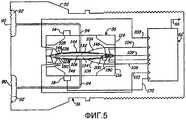
Фиг.5 - упрощенный разрез измерительного преобразователя по фиг.3, иллюстрирующий датчик давления.FIG. 5 is a simplified sectional view of the transmitter of FIG. 3, illustrating a pressure sensor.
Подробное описаниеDetailed description
Как рассматривалось в разделе, относящемся к уровню техники, датчики давления используют при различных производственных процессах и в установках контроля с измерительными преобразователями давления. Для измерения давления используют несколько различных методик. Например, давление, прикладываемое к отклоняющейся мембране, может быть измерено на основании изменения электрической емкости, измеряемой между мембраной и электродом. В других методиках измерения используют, например, результат измерения механического напряжения или других характеристик компонента, которые изменяются в ответ на приложенное давление.As discussed in the section related to the prior art, pressure sensors are used in various production processes and in monitoring installations with pressure transmitters. Several different techniques are used to measure pressure. For example, the pressure applied to the deflectable membrane can be measured based on the change in electrical capacitance measured between the membrane and the electrode. Other measurement techniques use, for example, a result of measuring mechanical stress or other characteristics of a component that change in response to an applied pressure.
Настоящим изобретением обеспечивается датчик давления, в котором приложенное давление измеряют на основании изменения акустического сигнала, который проходит через текучую среду, находящуюся под давлением. Акустическое входное устройство или источник находится в связи с текучей средой для излучения акустического сигнала. Акустический детектор или приемник принимает сигнал. Измерительные схемы могут быть сконфигурированы для получения на основании принятого сигнала выходного сигнала, зависящего от давления текучей среды.The present invention provides a pressure sensor in which the applied pressure is measured based on a change in an acoustic signal that passes through a pressurized fluid. An acoustic input device or source is in communication with a fluid for emitting an acoustic signal. An acoustic detector or receiver receives a signal. The measurement circuits may be configured to obtain, based on the received signal, an output signal depending on the pressure of the fluid.
Согласно настоящему изобретению может использоваться известное соотношение между скоростью акустического сигнала, проходящего через текучую среду, температурой и давлением текучей среды. Например, известно, что скорость звука в морской воде зависит от температуры, солености и давления воды.According to the present invention, a known relationship between the speed of an acoustic signal passing through a fluid, temperature and pressure of a fluid can be used. For example, it is known that the speed of sound in seawater depends on temperature, salinity, and water pressure.
На фиг.1 представлен график зависимости глубины в такой среде от скорости. На графике из фиг.1 скорость акустического сигнала сначала уменьшается в зависимости от глубины. Это обусловлено снижением температуры воды. Однако по мере того как на больших глубинах температура воды становится постоянной, скорость начинает возрастать с увеличением глубины (давления). В воде скорость звука находится в пределах от около 1400 до около 1570 м/с (от 4593 до 5151 фут/с). Это составляет около 1,5 км/с (немного меньше 1 мили в секунду) или в 4 раза быстрее, чем звук распространяется в воздухе.Figure 1 presents a graph of the dependence of depth in such an environment on speed. In the graph of FIG. 1, the speed of the acoustic signal first decreases with depth. This is due to a decrease in water temperature. However, as the water temperature becomes constant at great depths, the speed begins to increase with increasing depth (pressure). In water, the speed of sound ranges from about 1400 to about 1570 m / s (from 4593 to 5151 ft / s). This is about 1.5 km / s (slightly less than 1 mile per second), or 4 times faster than sound propagating through the air.
Кроме того, в дисперсионной среде, такой как вода, скорость звука является функцией частоты. Это означает, что распространяющиеся акустические возмущения будут непрерывно изменяться, поскольку каждая частотная составляющая распространяется со своей фазовой скоростью, тогда как энергия возмущения распространяется с групповой скоростью. С другой стороны, воздух представляет собой недисперсионную среду, и скорость звука не зависит от частоты. Поэтому в воздухе скорость переноса энергии и скорость распространения звука являются одинаковыми.In addition, in a dispersion medium such as water, the speed of sound is a function of frequency. This means that the propagating acoustic disturbances will continuously change, since each frequency component propagates with its own phase velocity, while the disturbance energy propagates with a group velocity. On the other hand, air is a non-dispersive medium, and the speed of sound is independent of frequency. Therefore, in air, the speed of energy transfer and the speed of sound propagation are the same.
На фиг.2 представлен упрощенный вид датчика 10 давления согласно одному варианту осуществления. Датчик 10 давления содержит удерживающую давление структуру 12, которая содержит текучую среду под давлением технологической текучей среды. Это может быть сама технологическая текучая среда или изолированная текучая среда, которая подвергается воздействию того же самого давления со стороны технологической текучей среды. Акустическое входное устройство или источник 14 связан с удерживающей давление структурой 12 и сконфигурирован для излучения акустического сигнала 16 через текучую среду в удерживающей давление структуре 12. Акустический детектор или приемник 18 принимает акустический сигнал 16 и в ответ формирует выходной сигнал. Акустическое входное устройство 14 и акустический детектор 18 соединены с измерительными схемами 20. Измерительные схемы 20 определяют давление текучей среды в удерживающей давление структуре на основании известного соотношения между давлением текучей среды и изменениями акустического сигнала 16. Также показан необязательный датчик 22 температуры, который обеспечивает сигнал температуры для измерительных схем 20. Этот сигнал температуры может быть использован измерительными схемами 20 для компенсации зависящего от давления выходного сигнала 24 на основании температуры текучей среды и удерживающей давление структуры 12.2 is a simplified view of a pressure sensor 10 according to one embodiment. The pressure sensor 10 comprises a pressure holding structure 12, which contains a fluid under pressure from the process fluid. This may be the process fluid itself or an isolated fluid that is exposed to the same pressure from the process fluid. An acoustic input device or source 14 is coupled to the pressure-holding structure 12 and configured to emit the acoustic signal 16 through the fluid in the pressure-holding structure 12. The acoustic detector or
В связанном примере конфигурации соотношение между температурой, давлением и акустической сигнатурой, рассмотренное выше, используется в устройстве, показанном на фиг.2, для определения температуры текучей среды в удерживающей давление структуре 12. В такой конфигурации выходной сигнал акустического детектора 18 является зависящим от температуры текучей среды в структуре 12. Если давление текучей среды в структуре 12 является относительно постоянным, измерительные схемы 20 могут формировать выходной сигнал 24, зависящий от температуры текучей среды. В другом примере конфигурации датчик 22 может представлять собой датчик давления, а не датчик температуры. В такой конфигурации измерительные схемы 20 компенсируют выходной сигнал температуры на основании давления, определенного с использованием датчика 22 давления.In a related configuration example, the relationship between temperature, pressure and acoustic signature discussed above is used in the device shown in FIG. 2 to determine the temperature of the fluid in the pressure-holding structure 12. In this configuration, the output of the
Устройство и методика, рассмотренные выше со ссылками на фиг.1 и 2, могут быть полезными для ряда применений в системах контроля и регулирования производственных процессов. Например, для измерительных преобразователей, которые измеряют как дифференциальное давление, так и линейное давление, обычно необходимы два отдельных датчика давления. Один датчик давления конфигурируют для измерения дифференциального давления, тогда как второй датчик давления используют для измерения линейного давления. Хотя этим обеспечивается точное измерение, но для этого требуются большие затраты и дополнительные компоненты. Кроме того, также может ухудшиться характеристика вследствие того, что может быть рассогласование между изолированной наполнительной текучей средой, используемой для изоляции датчиков давления, от технологической текучей среды. Это рассогласование может возникать между двумя сторонами датчика дифференциального давления, которые связаны с технологической текучей средой. В конфигурации на фиг.2 линейное давление может быть измерено с использованием такого же датчика, какой используется для измерения дифференциального давления. В частности, в такой конфигурации удерживающая давление структура 12 содержит устройство с датчиком дифференциального давления. Акустическое входное устройство 14 и детектор 18 связаны с текучей средой в системе, которая находится под давлением технологической текучей среды. Например, эта текучая среда может быть изолированной текучей средой, которая находится между разделительными мембранами измерительного преобразователя давления и центральной мембраной датчика давления. Входное устройство 14 и детектор 18 связаны с трубой, которая заключает в себе изолированную текучую среду, или они могут быть установлены непосредственно на самом датчике давления.The device and methodology discussed above with reference to figures 1 and 2, may be useful for a number of applications in systems of control and regulation of production processes. For example, for transmitters that measure both differential pressure and line pressure, two separate pressure sensors are usually required. One pressure sensor is configured to measure differential pressure, while a second pressure sensor is used to measure linear pressure. Although this provides accurate measurement, it requires high costs and additional components. In addition, performance may also deteriorate due to a mismatch between the insulated filling fluid used to isolate the pressure sensors from the process fluid. This mismatch may occur between the two sides of the differential pressure sensor that are associated with the process fluid. In the configuration of FIG. 2, linear pressure can be measured using the same sensor as that used to measure differential pressure. In particular, in this configuration, the pressure holding structure 12 comprises a device with a differential pressure sensor. The acoustic inlet 14 and
В другом примере конфигурации удерживающая давление структура 12 является частью устройства с датчиками линейного или манометрического давления. В такой конфигурации акустический сигнал 16 может быть использован для осуществления операции диагностического контроля датчика линейного давления. Например, может быть осуществлено сравнение показаний датчика линейного давления с ожидаемыми показаниями от акустического сигнала 16. Если акустический сигнал 16 не является таким, как ожидаемый сигнал, может быть выдано предупреждение, указывающее на то, что устройство работает не так, как предполагалось, и может быть неисправным. Можно сделать так, чтобы такое указание обеспечивалось до возникновения фактического отказа, то есть обеспечивалась возможность проведения предупредительного ремонта. В связанной конфигурации акустический сигнал используется совместно с измеренным линейным давлением для получения оценки температуры текучей среды.In another configuration example, the pressure retaining structure 12 is part of a device with linear or gauge pressure sensors. In such a configuration, the acoustic signal 16 can be used to perform the diagnostic monitoring operation of the linear pressure sensor. For example, a line pressure sensor may be compared with the expected readings from the acoustic signal 16. If the acoustic signal 16 is not the same as the expected signal, a warning may be issued indicating that the device is not working as intended and may to be faulty. It is possible to ensure that such an indication is provided before the actual failure occurs, that is, the possibility of preventive maintenance is provided. In a related configuration, an acoustic signal is used in conjunction with a measured linear pressure to obtain an estimate of the temperature of the fluid.
На фиг.3 показано в общих чертах периферийное оборудование системы 32 измерения параметров процесса, включающее в себя измерительный преобразователь 36 давления процесса, сконфигурированный для реализации настоящего изобретения. На фиг.3 показан технологический трубопровод 30, содержащий текучую среду под давлением, связанную с системой 32 измерения параметров процесса, предназначенной для измерения давления процесса. Система 32 измерения параметров процесса включает в себя импульсный трубопровод 34, соединенный с трубопроводом 30. Импульсный трубопровод 34 соединен с измерительным преобразователем 36 давления процесса. Чувствительный элемент 33, такой как измерительная диафрагма, трубка Вентури, расходомерное сопло и т.д., соприкасается с технологической текучей средой в технологическом трубопроводе 30 в месте, находящемся между трубами импульсного трубопровода 34. Чувствительный элемент 33 вызывает изменение давления в текучей среде, когда она проходит через чувствительный элемент 33.FIG. 3 shows, in general terms, the peripheral equipment of a process
Измерительный преобразователь 36 представляет собой устройство для измерения параметров процесса, которое воспринимает давления процесса в импульсном трубопроводе 34. Измерительный преобразователь 36 определяет дифференциальное давление процесса и преобразует его в стандартизованный сигнал передачи, который является функцией давления процесса.The
Контур 38 процесса обеспечивает сигнал питания для измерительного преобразователя 36 с поста 40 управления и двунаправленную связь, и он может быть выполнен в соответствии с рядом протоколов обмена данными процесса. В показанном примере контур 38 процесса представляет собой двухпроводный контур. При нормальной работе двухпроводный контур используется для передачи любой электрической энергии ко всем средствам связи и к измерительному преобразователю 36, а от него сигнала 4-20 мА. Компьютер 42 или другая система обработки информации используется для связи с измерительным преобразователем 36 через модем 44 или другой сетевой интерфейс. Удаленный источник 46 напряжения обычно снабжает электрической энергией измерительный преобразователь 36.The
На фиг.4 представлена упрощенная структурная схема иллюстративного измерительного преобразователя 36 давления. В этом примере измерительный преобразователь 36 давления включает в себя сенсорный модуль 52 и плату 72 электроники, соединенные друг с другом через шину 66 данных. Электроника 60 сенсорного модуля соединена с датчиком 56 давления, который воспринимает приложенное дифференциальное давление 54. Линия 58 данных соединяет датчик 56 с аналого-цифровым преобразователем 62. Также показан необязательный датчик 63 температуры, равно как и запоминающее устройство (ЗУ) 64 сенсорного модуля. Плата 72 электроники включает в себя микрокомпьютерную систему 74, запоминающее устройство (ЗУ) 76 модуля электроники, схемы 78 цифроаналогового преобразования сигналов и блок 80 цифровой связи. Схемы 78 цифроаналогового преобразования могут обеспечивать выходной сигнал любого вида, имеющий отношение к датчику давления, включая, например, скорость потока технологической текучей среды, которая определяется на основании дифференциального давления. Выходные сигналы других видов включают в себя указания на давления процесса, диагностические выходные сигналы, температурные данные или другие.Figure 4 presents a simplified block diagram of an
Согласно способам, изложенным в патенте США №6295875 (Frick et al.), измерительный преобразователь 36 давления определяет дифференциальное давление. Однако настоящее изобретение не ограничено такой конфигурацией.According to the methods set forth in US patent No. 6295875 (Frick et al.), The
На фиг.4 также показан акустический источник 14, связанный с источником 14, и акустический датчик 18, связанный с датчиком 56 давления. Акустический сигнал 16 от источника проходит через находящуюся под давлением текучую среду в датчике 56 и принимается датчиком 18. Выходной сигнал датчика 18 подается на аналого-цифровой преобразователь 62. В микрокомпьютерной системе 74 принимается оцифрованный сигнал от датчика 18 и определяется линейное давление с использованием способов, рассмотренных выше.FIG. 4 also shows an acoustic source 14 connected to a source 14 and an
На фиг.5 представлен упрощенный разрез сенсорного модуля 52 согласно одному осуществлению с показом датчика 56 давления. Датчик 56 давления связан с технологической текучей средой через разделительные мембраны 90, которые изолируют технологическую текучую среду от полостей 92. Полости 92 соединены с сенсорным модулем 56 давления по импульсному трубопроводу 94. По существу несжимаемая наполнительная текучая среда заполняет полости 92 и импульсный трубопровод 94. Когда давление от технологической текучей среды прикладывается к мембранам 90, оно передается на датчик 56 давления.5 is a simplified sectional view of a
Датчик 56 давления образован из двух половин 114 и 116 датчика давления, и он заполнен предпочтительно хрупким, по существу несжимаемым материалом 105. Мембрана 106 подвешена внутри полости 132, 134, образованной внутри датчика 56. Внешняя стенка полости 132, 134 содержит электроды 146, 144, 148 и 150. В общем, они могут быть названы первичными электродами 144 и 148 и вторичными или дополнительными электродами 146 и 150. Эти электроды образуют конденсаторы относительно подвижной мембраны 106. И вновь конденсаторы могут быть названы первичными и вторичными конденсаторами.The
Как показано на фиг.5, различные электроды в датчике 56 соединены с аналого-цифровым преобразователем 62 посредством электрических соединений 103, 104, 108 и 110. Кроме того, отклоняемая мембрана 106 соединена с аналого-цифровым преобразователем 62 посредством соединения 109. Как рассмотрено в патенте США №6295875, дифференциальное давление, прикладываемое к датчику 56, может быть измерено с использованием электродов 144-150.As shown in FIG. 5, various electrodes in the
На фиг.5 также показаны акустический источник 14 и акустический датчик 18, рассмотренные выше. Электрическое соединение 170 предусмотрено от акустического датчика 18 к аналого-цифровому преобразователю 62 сигналов. Акустический источник 14 может работать независимо или может работать под управлением схем в измерительном преобразователе. Например, акустический источник 14 может управляться схемами в сенсорном модуле 52 или на плате 72 электроники из фиг.4.5 also shows an acoustic source 14 and an
Как показано на фиг.5, вследствие позиционирования источника 14 и датчика 18 акустический сигнал 16 (не показанный на фиг.5) будет проходить через датчик 56 и проходить через наполнительную текучую среду, содержащуюся в полости датчика. Эта наполнительная текучая среда находится под давлением вследствие связи с технологической текучей средой по импульсному трубопроводу 94 и через разделительную мембрану 90.As shown in FIG. 5, due to the positioning of the source 14 and the
Хотя на фиг.4 и 5 показан датчик дифференциального давления с использованием отклоняемой мембраны, настоящее изобретение может быть реализовано с датчиком давления любого вида. Как рассматривалось выше, настоящее изобретение также может быть реализовано с автономным датчиком давления. Кроме того, акустический сигнал может находиться в связи с любой точкой в системе, в которой имеется текучая среда под давлением. Например, акустический сигнал может быть связан с капиллярными трубками 94 или полостями 92, показанными на фиг.5. В дополнение к определению линейного давления, рассмотренного выше, акустический сигнал также может быть использован для измерения шума быстродействующего процесса, что может быть использовано, например, при диагностическом контроле. Акустический сигнал может быть на одной частоте, на изменяющейся частоте или на нескольких частотах для улучшения характеристик измерения. В другом примере конфигурации акустический сигнал 16 образуется непосредственно из шума в рамках самого процесса. В такой конфигурации элемент 14, показанный выше, может содержать второй акустический датчик. В такой конфигурации время пробега шумового сигнала между датчиками 14 и 18 может быть использовано для получения линейного давления. В еще одном примере два датчика используются для измерения дисперсии шума процесса между двумя точками. Затем эта информация может быть использована для получения линейного давления. В еще одной примерной конфигурации предусмотрен дополнительный акустический датчик 200, показанный на фиг.5. Акустический датчик 200 вводят в какое-либо место между источником 14 и приемником 18, например внутрь полости 92. Этот дополнительный датчик 200 может быть использован для обнаружения задержки шума процесса в модуле. Например, существующим датчиком давления можно обнаруживать низкочастотный шум процесса. Дополнительный датчик 200 может быть использован для обнаружения задержки шума процесса в модуле и может быть выполнение сравнение с акустическим сигналом, обнаруживаемым электродом 144 или 148 датчика.Although FIGS. 4 and 5 show a differential pressure sensor using a deflectable diaphragm, the present invention can be implemented with any type of pressure sensor. As discussed above, the present invention can also be implemented with a stand-alone pressure sensor. In addition, the acoustic signal may be in communication with any point in the system in which there is fluid under pressure. For example, an acoustic signal may be coupled to
Хотя настоящее изобретение было описано применительно к предпочтительным осуществлениям, специалисты в данной области техники должны признавать, что изменения по форме и в деталях могут быть сделаны без отступления от сущности и объема изобретения.Although the present invention has been described with reference to preferred embodiments, those skilled in the art will recognize that changes in form and detail can be made without departing from the spirit and scope of the invention.
Claims (19)
Translated fromRussianакустический детектор, связанный с удерживающей давление структурой, сконфигурированный для приема акустического сигнала, распространяющегося через удерживающую давление структуру, и обеспечения акустического выходного сигнала; и измерительную схемотехнику, соединенную с удерживающей давление структурой и акустическим детектором, имеющую выходной сигнал, зависящий от давления текучей среды как функцию выходного сигнала давления и акустического выходного сигнала.1. A measuring transducer configured to measure a process parameter of a manufacturing process, comprising: a pressure sensor comprising a pressure-retaining structure, the pressure sensor configured to communicate with a fluid pressure and provide a pressure output signal depending on the process pressure, the pressure sensor connected to the process pipeline through a pulse pipeline, whereby the pressure sensor structure is spaced apart from the process pipeline, which is transported it is a process fluid, the impulse conduit transferring an isolated fluid that is connected to the process fluid through a separation membrane;
an acoustic detector coupled to the pressure holding structure configured to receive an acoustic signal propagating through the pressure holding structure and providing an acoustic output signal; and measuring circuitry connected to the pressure holding structure and an acoustic detector having an output signal depending on the pressure of the fluid as a function of the pressure output signal and the acoustic output signal.
связывают датчик давления с текучей средой процесса через импульсный трубопровод, переносящий изолированную текучую среду, которая связана с текучей средой процесса через разделительную мембрану, причем датчик давления содержит удерживающую давление структуру;
измеряют давление текучей среды процесса, используя датчик давления, связанный с текучей средой процесса и обеспечивающий выходной сигнал, зависящий от давления процесса;
принимают акустический сигнал, который распространяется через удерживающую давление структуру; и
получают выходной сигнал, зависящий от давления текучей среды процесса, на основании акустического сигнала и давления процесса.12. The method of measuring the technological parameter of the production process, which consists in the fact that:
connecting the pressure sensor to the process fluid through a pulsed conduit carrying an isolated fluid that is connected to the process fluid through a separation membrane, the pressure sensor comprising a pressure holding structure;
measuring the process fluid pressure using a pressure sensor associated with the process fluid and providing an output signal depending on the process pressure;
receiving an acoustic signal that propagates through the pressure holding structure; and
receiving an output signal depending on the process fluid pressure based on the acoustic signal and the process pressure.
Applications Claiming Priority (2)
| Application Number | Priority Date | Filing Date | Title |
|---|---|---|---|
| US11/238,654US7379792B2 (en) | 2005-09-29 | 2005-09-29 | Pressure transmitter with acoustic pressure sensor |
| US11/238,654 | 2005-09-29 |
Publications (2)
| Publication Number | Publication Date |
|---|---|
| RU2008116824A RU2008116824A (en) | 2009-11-10 |
| RU2421698C2true RU2421698C2 (en) | 2011-06-20 |
Family
ID=37636085
Family Applications (1)
| Application Number | Title | Priority Date | Filing Date |
|---|---|---|---|
| RU2008116824/28ARU2421698C2 (en) | 2005-09-29 | 2006-09-19 | Pressure transducer with acoustic pressure sensor |
Country Status (7)
| Country | Link |
|---|---|
| US (1) | US7379792B2 (en) |
| EP (1) | EP1929264B1 (en) |
| JP (1) | JP5743378B2 (en) |
| CN (1) | CN101273257B (en) |
| CA (1) | CA2621313C (en) |
| RU (1) | RU2421698C2 (en) |
| WO (1) | WO2007040980A1 (en) |
Families Citing this family (10)
| Publication number | Priority date | Publication date | Assignee | Title |
|---|---|---|---|---|
| DE102008043467A1 (en)* | 2008-11-04 | 2010-05-06 | Endress + Hauser Gmbh + Co. Kg | Device for determining and / or monitoring a pressure |
| US8234927B2 (en)* | 2010-06-08 | 2012-08-07 | Rosemount Inc. | Differential pressure sensor with line pressure measurement |
| US9470084B2 (en)* | 2010-08-12 | 2016-10-18 | Rosemount Inc. | Method and apparatus for measuring fluid process variable in a well |
| US8448519B2 (en)* | 2010-10-05 | 2013-05-28 | Rosemount Inc. | Industrial process transmitter with high static pressure isolation diaphragm coupling |
| CN102095466B (en)* | 2010-11-26 | 2012-10-17 | 中国航空工业集团公司北京长城计量测试技术研究所 | Volume measurement method based on sound generating principle of piston |
| US9423315B2 (en)* | 2013-10-15 | 2016-08-23 | Rosemount Aerospace Inc. | Duplex pressure transducers |
| CN104775884B (en)* | 2014-01-09 | 2019-11-08 | 罗伯特·博世有限公司 | Method and apparatus for running internal combustion engine |
| KR102258580B1 (en) | 2020-04-16 | 2021-06-01 | 한국원자력연구원 | Pressure transmitter |
| CN116194217A (en)* | 2020-08-03 | 2023-05-30 | 株式会社日立高新技术 | Dispensing device and method |
| US20240240977A1 (en)* | 2023-01-13 | 2024-07-18 | Honeywell International Inc. | Systems, apparatuses, and methods for fluid flow detection |
Citations (5)
| Publication number | Priority date | Publication date | Assignee | Title |
|---|---|---|---|---|
| SU746219A1 (en)* | 1978-07-03 | 1980-07-07 | Предприятие П/Я А-1874 | Pressure sensor with frequency output |
| RU2028584C1 (en)* | 1985-04-01 | 1995-02-09 | Научно-исследовательский институт физических измерений | Method of tuning thin-film pressure transducer |
| RU2028588C1 (en)* | 1987-12-01 | 1995-02-09 | Научно-исследовательский институт физических измерений | Thin-film pressure transducer |
| RU2092801C1 (en)* | 1988-02-02 | 1997-10-10 | Научно-исследовательский институт физических измерений | Thin-film pressure pickup |
| WO2005066590A2 (en)* | 2003-12-23 | 2005-07-21 | Rosemount Inc. | Diagnostics of impulse piping in an industrial process |
Family Cites Families (101)
| Publication number | Priority date | Publication date | Assignee | Title |
|---|---|---|---|---|
| US2533339A (en)* | 1946-06-22 | 1950-12-12 | Jabez Burns & Sons Inc | Flammable vapor protection |
| US3012432A (en)* | 1957-09-23 | 1961-12-12 | Richard H Moore | Leak tester |
| GB1023042A (en)* | 1962-05-07 | 1966-03-16 | Wayne Kerr Lab Ltd | Improvements in or relating to pressure responsive apparatus |
| US3232712A (en)* | 1962-08-16 | 1966-02-01 | Continental Lab Inc | Gas detector and analyzer |
| US3374112A (en)* | 1964-03-05 | 1968-03-19 | Yeda Res & Dev | Method and apparatus for controlled deposition of a thin conductive layer |
| US3249833A (en)* | 1964-11-16 | 1966-05-03 | Robert E Vosteen | Capacitor transducer |
| US3557621A (en)* | 1969-07-07 | 1971-01-26 | C G S Scient Corp Inc | Variable capacitance detecting devices |
| GB1354025A (en)* | 1970-05-25 | 1974-06-05 | Medicor Muevek | Capacitive pressure transducer |
| US3924219A (en)* | 1971-12-22 | 1975-12-02 | Minnesota Mining & Mfg | Gas detection device |
| US3808480A (en)* | 1973-04-16 | 1974-04-30 | Bunker Ramo | Capacitive pressure transducer |
| US4008619A (en) | 1975-11-17 | 1977-02-22 | Mks Instruments, Inc. | Vacuum monitoring |
| US4177496A (en)* | 1976-03-12 | 1979-12-04 | Kavlico Corporation | Capacitive pressure transducer |
| US4158217A (en)* | 1976-12-02 | 1979-06-12 | Kaylico Corporation | Capacitive pressure transducer with improved electrode |
| US4120206A (en)* | 1977-01-17 | 1978-10-17 | Rosemount Inc. | Differential pressure sensor capsule with low acceleration sensitivity |
| US4168518A (en)* | 1977-05-10 | 1979-09-18 | Lee Shih Y | Capacitor transducer |
| US4227419A (en)* | 1979-09-04 | 1980-10-14 | Kavlico Corporation | Capacitive pressure transducer |
| US4244226A (en)* | 1979-10-04 | 1981-01-13 | Honeywell Inc. | Distance measuring apparatus and a differential pressure transmitter utilizing the same |
| US4434451A (en)* | 1979-10-29 | 1984-02-28 | Delatorre Leroy C | Pressure sensors |
| US4322775A (en)* | 1979-10-29 | 1982-03-30 | Delatorre Leroy C | Capacitive pressure sensor |
| US4287553A (en)* | 1980-06-06 | 1981-09-01 | The Bendix Corporation | Capacitive pressure transducer |
| US4336567A (en)* | 1980-06-30 | 1982-06-22 | The Bendix Corporation | Differential pressure transducer |
| US4370890A (en)* | 1980-10-06 | 1983-02-01 | Rosemount Inc. | Capacitive pressure transducer with isolated sensing diaphragm |
| US4358814A (en)* | 1980-10-27 | 1982-11-09 | Setra Systems, Inc. | Capacitive pressure sensor |
| US4422335A (en)* | 1981-03-25 | 1983-12-27 | The Bendix Corporation | Pressure transducer |
| US4458537A (en)* | 1981-05-11 | 1984-07-10 | Combustion Engineering, Inc. | High accuracy differential pressure capacitive transducer |
| US4389895A (en)* | 1981-07-27 | 1983-06-28 | Rosemount Inc. | Capacitance pressure sensor |
| US4466290A (en)* | 1981-11-27 | 1984-08-21 | Rosemount Inc. | Apparatus for conveying fluid pressures to a differential pressure transducer |
| US4455874A (en)* | 1981-12-28 | 1984-06-26 | Paroscientific, Inc. | Digital pressure transducer |
| US4422125A (en)* | 1982-05-21 | 1983-12-20 | The Bendix Corporation | Pressure transducer with an invariable reference capacitor |
| DE3238430A1 (en) | 1982-10-16 | 1984-04-19 | Philips Patentverwaltung Gmbh, 2000 Hamburg | DIFFERENTIAL PRESSURE SENSOR |
| US4558184A (en) | 1983-02-24 | 1985-12-10 | At&T Bell Laboratories | Integrated capacitive transducer |
| US4490773A (en)* | 1983-12-19 | 1984-12-25 | United Technologies Corporation | Capacitive pressure transducer |
| US4542436A (en)* | 1984-04-10 | 1985-09-17 | Johnson Service Company | Linearized capacitive pressure transducer |
| US4562742A (en)* | 1984-08-07 | 1986-01-07 | Bell Microcomponents, Inc. | Capacitive pressure transducer |
| US4578735A (en) | 1984-10-12 | 1986-03-25 | Knecht Thomas A | Pressure sensing cell using brittle diaphragm |
| US4586108A (en) | 1984-10-12 | 1986-04-29 | Rosemount Inc. | Circuit for capacitive sensor made of brittle material |
| US4670733A (en)* | 1985-07-01 | 1987-06-02 | Bell Microsensors, Inc. | Differential pressure transducer |
| JPS62187820U (en)* | 1986-05-22 | 1987-11-30 | ||
| US4860232A (en)* | 1987-04-22 | 1989-08-22 | Massachusetts Institute Of Technology | Digital technique for precise measurement of variable capacitance |
| FR2614986B1 (en) | 1987-05-07 | 1989-08-18 | Otic Fischer & Porter | CAPACITIVE CELL STRUCTURE FOR MEASURING DIFFERENTIAL PRESSURES |
| US4785669A (en)* | 1987-05-18 | 1988-11-22 | Mks Instruments, Inc. | Absolute capacitance manometers |
| US4875369A (en)* | 1987-09-08 | 1989-10-24 | Panex Corporation | Pressure sensor system |
| US4945768A (en)* | 1988-05-20 | 1990-08-07 | Parker Electronics, Inc. | Pressure sensor |
| US4878012A (en)* | 1988-06-10 | 1989-10-31 | Rosemount Inc. | Charge balanced feedback transmitter |
| US4977480A (en)* | 1988-09-14 | 1990-12-11 | Fuji Koki Mfg. Co., Ltd. | Variable-capacitance type sensor and variable-capacitance type sensor system using the same |
| US5637302A (en)* | 1988-09-20 | 1997-06-10 | Indena Spa | Extracts of Ginkgo biloba and their methods of preparation |
| US4926674A (en)* | 1988-11-03 | 1990-05-22 | Innovex Inc. | Self-zeroing pressure signal generator |
| US4951174A (en)* | 1988-12-30 | 1990-08-21 | United Technologies Corporation | Capacitive pressure sensor with third encircling plate |
| US5040415A (en) | 1990-06-15 | 1991-08-20 | Rockwell International Corporation | Nonintrusive flow sensing system |
| US5194819A (en)* | 1990-08-10 | 1993-03-16 | Setra Systems, Inc. | Linearized capacitance sensor system |
| US5094109A (en)* | 1990-12-06 | 1992-03-10 | Rosemount Inc. | Pressure transmitter with stress isolation depression |
| US5168419A (en)* | 1991-07-16 | 1992-12-01 | Panex Corporation | Capacitor and pressure transducer |
| US5230250A (en)* | 1991-09-03 | 1993-07-27 | Delatorre Leroy C | Capacitor and pressure transducer |
| JP3182807B2 (en)* | 1991-09-20 | 2001-07-03 | 株式会社日立製作所 | Multifunctional fluid measurement transmission device and fluid volume measurement control system using the same |
| US5233875A (en)* | 1992-05-04 | 1993-08-10 | Kavlico Corporation | Stable capacitive pressure transducer system |
| US5329818A (en)* | 1992-05-28 | 1994-07-19 | Rosemount Inc. | Correction of a pressure indication in a pressure transducer due to variations of an environmental condition |
| US5492016A (en)* | 1992-06-15 | 1996-02-20 | Industrial Sensors, Inc. | Capacitive melt pressure measurement with center-mounted electrode post |
| JPH06102127A (en)* | 1992-09-22 | 1994-04-15 | Yokogawa Electric Corp | Pressure / differential pressure transmitter |
| JPH0712667A (en)* | 1993-06-29 | 1995-01-17 | Hitachi Ltd | Physical quantity sensor and physical quantity sensor system |
| JP3341091B2 (en)* | 1993-06-29 | 2002-11-05 | 耕司 戸田 | Ultrasonic displacement sensor |
| CA2169824A1 (en)* | 1993-09-24 | 1995-03-30 | Roger L. Frick | Pressure transmitter isolation diaphragm |
| DE4333753A1 (en) | 1993-10-04 | 1994-05-11 | Bosch Gmbh Robert | Capacitive difference pressure sensor - has carrier supporting counter-electrodes between facing membranes carrying capacitor electrodes |
| US5542300A (en)* | 1994-01-24 | 1996-08-06 | Setra Systems, Inc. | Low cost, center-mounted capacitive pressure sensor |
| US5642301A (en)* | 1994-01-25 | 1997-06-24 | Rosemount Inc. | Transmitter with improved compensation |
| US5415048A (en)* | 1994-06-27 | 1995-05-16 | Texaco Inc. | Acoustic gas-liquid flow meter |
| AU4110596A (en)* | 1994-11-30 | 1996-06-19 | Rosemount Inc. | Pressure transmitter with fill fluid loss detection |
| US5637802A (en) | 1995-02-28 | 1997-06-10 | Rosemount Inc. | Capacitive pressure sensor for a pressure transmitted where electric field emanates substantially from back sides of plates |
| US6484585B1 (en)* | 1995-02-28 | 2002-11-26 | Rosemount Inc. | Pressure sensor for a pressure transmitter |
| US5705978A (en)* | 1995-09-29 | 1998-01-06 | Rosemount Inc. | Process control transmitter |
| US5992240A (en)* | 1995-11-21 | 1999-11-30 | Fuji Electric Co., Ltd. | Pressure detecting apparatus for measuring pressure based on detected capacitance |
| US5757608A (en)* | 1996-01-25 | 1998-05-26 | Alliedsignal Inc. | Compensated pressure transducer |
| US6654697B1 (en)* | 1996-03-28 | 2003-11-25 | Rosemount Inc. | Flow measurement with diagnostics |
| US5668322A (en)* | 1996-06-13 | 1997-09-16 | Rosemount Inc. | Apparatus for coupling a transmitter to process fluid having a sensor extension selectively positionable at a plurality of angles |
| DE19633630A1 (en) | 1996-08-21 | 1998-02-26 | Endress Hauser Gmbh Co | Evaluation unit of a differential pressure sensor |
| US20040015069A1 (en)* | 1996-12-27 | 2004-01-22 | Brown David Lloyd | System for locating inflamed plaque in a vessel |
| US5911162A (en)* | 1997-06-20 | 1999-06-08 | Mks Instruments, Inc. | Capacitive pressure transducer with improved electrode support |
| JPH1151795A (en)* | 1997-08-08 | 1999-02-26 | Saginomiya Seisakusho Inc | Semiconductor pressure sensor and manufacturing method thereof |
| ATE213326T1 (en) | 1998-04-09 | 2002-02-15 | Heinz Ploechinger | CAPACITIVE PRESSURE OR FORCE SENSING STRUCTURE AND METHOD FOR PRODUCING THE SAME |
| JP3567089B2 (en) | 1998-10-12 | 2004-09-15 | 株式会社日立製作所 | Capacitive pressure sensor |
| US6301973B1 (en)* | 1999-04-30 | 2001-10-16 | The United States Of America As Represented By The Administrator Of The National Aeronautics And Space Administration | Non-intrusive pressure/multipurpose sensor and method |
| US6295875B1 (en)* | 1999-05-14 | 2001-10-02 | Rosemount Inc. | Process pressure measurement devices with improved error compensation |
| EP1207378B1 (en) | 1999-08-20 | 2007-08-08 | Hitachi, Ltd. | Semiconductor pressure sensor and pressure sensing device |
| US6701274B1 (en)* | 1999-08-27 | 2004-03-02 | Rosemount Inc. | Prediction of error magnitude in a pressure transmitter |
| US6484107B1 (en)* | 1999-09-28 | 2002-11-19 | Rosemount Inc. | Selectable on-off logic modes for a sensor module |
| US6520020B1 (en)* | 2000-01-06 | 2003-02-18 | Rosemount Inc. | Method and apparatus for a direct bonded isolated pressure sensor |
| US6612174B2 (en) | 2000-02-11 | 2003-09-02 | Rosemount Inc. | Optical pressure sensor |
| US6662662B1 (en)* | 2000-05-04 | 2003-12-16 | Rosemount, Inc. | Pressure transmitter with improved isolator system |
| US6516672B2 (en)* | 2001-05-21 | 2003-02-11 | Rosemount Inc. | Sigma-delta analog to digital converter for capacitive pressure sensor and process transmitter |
| US6828801B1 (en) | 2001-10-26 | 2004-12-07 | Welch Allyn, Inc. | Capacitive sensor |
| US7359803B2 (en)* | 2002-01-23 | 2008-04-15 | Cidra Corporation | Apparatus and method for measuring parameters of a mixture having solid particles suspended in a fluid flowing in a pipe |
| CA2474071C (en)* | 2002-01-23 | 2012-09-18 | Cidra Corporation | Apparatus and method for measuring parameters of a mixture having solid particles suspended in a fluid flowing in a pipe |
| US6675655B2 (en)* | 2002-03-21 | 2004-01-13 | Rosemount Inc. | Pressure transmitter with process coupling |
| US6647794B1 (en) | 2002-05-06 | 2003-11-18 | Rosemount Inc. | Absolute pressure sensor |
| EP1567833A2 (en)* | 2002-11-12 | 2005-08-31 | CiDra Corporation | An apparatus having an array of piezoelectric film sensors for measuring parameters of a process flow within a pipe |
| DE10310114A1 (en)* | 2003-03-06 | 2004-09-16 | Robert Bosch Gmbh | Device and method for hydrostatic pressure determination in a high pressure container by means of ultrasonic transit time measurement |
| US7197942B2 (en)* | 2003-06-05 | 2007-04-03 | Cidra Corporation | Apparatus for measuring velocity and flow rate of a fluid having a non-negligible axial mach number using an array of sensors |
| EP1646864B1 (en)* | 2003-07-18 | 2018-11-07 | Rosemount Inc. | Process diagnostics |
| US6945115B1 (en) | 2004-03-04 | 2005-09-20 | General Mems Corporation | Micromachined capacitive RF pressure sensor |
| US7577543B2 (en)* | 2005-03-11 | 2009-08-18 | Honeywell International Inc. | Plugged impulse line detection |
| US7401522B2 (en)* | 2005-05-26 | 2008-07-22 | Rosemount Inc. | Pressure sensor using compressible sensor body |
| US7334484B2 (en)* | 2005-05-27 | 2008-02-26 | Rosemount Inc. | Line pressure measurement using differential pressure sensor |
- 2005
- 2005-09-29USUS11/238,654patent/US7379792B2/ennot_activeExpired - Lifetime
- 2006
- 2006-09-19WOPCT/US2006/036404patent/WO2007040980A1/enactiveApplication Filing
- 2006-09-19EPEP06814912.9Apatent/EP1929264B1/ennot_activeCeased
- 2006-09-19JPJP2008538883Apatent/JP5743378B2/ennot_activeExpired - Fee Related
- 2006-09-19CACA2621313Apatent/CA2621313C/ennot_activeExpired - Fee Related
- 2006-09-19RURU2008116824/28Apatent/RU2421698C2/ennot_activeIP Right Cessation
- 2006-09-19CNCN2006800356927Apatent/CN101273257B/ennot_activeExpired - Fee Related
Patent Citations (5)
| Publication number | Priority date | Publication date | Assignee | Title |
|---|---|---|---|---|
| SU746219A1 (en)* | 1978-07-03 | 1980-07-07 | Предприятие П/Я А-1874 | Pressure sensor with frequency output |
| RU2028584C1 (en)* | 1985-04-01 | 1995-02-09 | Научно-исследовательский институт физических измерений | Method of tuning thin-film pressure transducer |
| RU2028588C1 (en)* | 1987-12-01 | 1995-02-09 | Научно-исследовательский институт физических измерений | Thin-film pressure transducer |
| RU2092801C1 (en)* | 1988-02-02 | 1997-10-10 | Научно-исследовательский институт физических измерений | Thin-film pressure pickup |
| WO2005066590A2 (en)* | 2003-12-23 | 2005-07-21 | Rosemount Inc. | Diagnostics of impulse piping in an industrial process |
Also Published As
| Publication number | Publication date |
|---|---|
| CN101273257A (en) | 2008-09-24 |
| EP1929264B1 (en) | 2018-04-04 |
| CN101273257B (en) | 2010-05-19 |
| CA2621313C (en) | 2014-11-25 |
| US20070073417A1 (en) | 2007-03-29 |
| WO2007040980A1 (en) | 2007-04-12 |
| CA2621313A1 (en) | 2007-04-12 |
| US7379792B2 (en) | 2008-05-27 |
| JP2009510483A (en) | 2009-03-12 |
| EP1929264A1 (en) | 2008-06-11 |
| JP5743378B2 (en) | 2015-07-01 |
| RU2008116824A (en) | 2009-11-10 |
Similar Documents
| Publication | Publication Date | Title |
|---|---|---|
| RU2421698C2 (en) | Pressure transducer with acoustic pressure sensor | |
| CA2873030C (en) | Differential pressure type flowmeter having redundant pressure sensors allowing sensor failure and degradation detection | |
| CN100504310C (en) | Shock piping diagnostics in industrial processes | |
| CA2893281C (en) | System and method for ultrasonic metering using an orifice meter fitting | |
| CN102243124B (en) | Based on the pressure transducer of resonance frequency | |
| US6988411B2 (en) | Fluid parameter measurement for industrial sensing applications using acoustic pressures | |
| RU2407997C2 (en) | Pressure sensor fault detection | |
| CA2516255C (en) | An apparatus and method of measuring gas volume fraction of a fluid flowing within a pipe | |
| US9970799B2 (en) | System of ultrasonic consumption meters with pressure sensors | |
| WO2004053430A2 (en) | Sensor arrangements and methods of determining a characteristic of a sample fluid using such sensor arrangements | |
| WO1996009561A1 (en) | Apparatus for sensor location | |
| CN116839794B (en) | Method for detecting pressure of liquid medium in pipeline by ultrasonic wave | |
| CA2506399C (en) | An apparatus and method for providing a flow measurement compensated for entrained gas | |
| CN111947722A (en) | Volume and mass flow detection method and device | |
| KR20230167824A (en) | well pipe monitoring apparatus using fiber optic accelerometer sensors |
Legal Events
| Date | Code | Title | Description |
|---|---|---|---|
| MM4A | The patent is invalid due to non-payment of fees | Effective date:20170920 |