RU2421253C1 - Multichannel electrode with independent bundle travel of microconductors - Google Patents
Multichannel electrode with independent bundle travel of microconductorsDownload PDFInfo
- Publication number
- RU2421253C1 RU2421253C1RU2009136914/14ARU2009136914ARU2421253C1RU 2421253 C1RU2421253 C1RU 2421253C1RU 2009136914/14 ARU2009136914/14 ARU 2009136914/14ARU 2009136914 ARU2009136914 ARU 2009136914ARU 2421253 C1RU2421253 C1RU 2421253C1
- Authority
- RU
- Russia
- Prior art keywords
- holder
- microconductors
- channel
- amplifier
- neurons
- Prior art date
Links
- 210000002569neuronAnatomy0.000claimsabstractdescription14
- 229910052751metalInorganic materials0.000claimsabstractdescription11
- 239000002184metalSubstances0.000claimsabstractdescription11
- 230000000638stimulationEffects0.000claimsabstractdescription10
- 230000000694effectsEffects0.000claimsabstractdescription8
- 230000001537neural effectEffects0.000abstractdescription11
- 210000004556brainAnatomy0.000abstractdescription8
- 241001465754MetazoaSpecies0.000abstractdescription3
- 230000002490cerebral effectEffects0.000abstract2
- 230000003247decreasing effectEffects0.000abstract1
- 239000003814drugSubstances0.000abstract1
- 239000000126substanceSubstances0.000abstract1
- 210000005013brain tissueAnatomy0.000description6
- 238000009413insulationMethods0.000description4
- 239000011521glassSubstances0.000description3
- KRHYYFGTRYWZRS-UHFFFAOYSA-NFluoraneChemical compoundFKRHYYFGTRYWZRS-UHFFFAOYSA-N0.000description2
- CZMRCDWAGMRECN-UGDNZRGBSA-NSucroseChemical compoundO[C@H]1[C@H](O)[C@@H](CO)O[C@@]1(CO)O[C@@H]1[C@H](O)[C@@H](O)[C@H](O)[C@@H](CO)O1CZMRCDWAGMRECN-UGDNZRGBSA-N0.000description2
- 229930006000SucroseNatural products0.000description2
- 239000011248coating agentSubstances0.000description2
- 238000000576coating methodMethods0.000description2
- 230000004807localizationEffects0.000description2
- 238000000034methodMethods0.000description2
- 210000003625skullAnatomy0.000description2
- 239000005720sucroseSubstances0.000description2
- 241000283973Oryctolagus cuniculusSpecies0.000description1
- 238000004458analytical methodMethods0.000description1
- 238000003491arrayMethods0.000description1
- 210000003926auditory cortexAnatomy0.000description1
- 210000000988bone and boneAnatomy0.000description1
- 210000003710cerebral cortexAnatomy0.000description1
- 239000004020conductorSubstances0.000description1
- 238000010586diagramMethods0.000description1
- 239000003989dielectric materialSubstances0.000description1
- 210000001951dura materAnatomy0.000description1
- 230000008030eliminationEffects0.000description1
- 238000003379elimination reactionMethods0.000description1
- 229920002313fluoropolymerPolymers0.000description1
- 239000003292glueSubstances0.000description1
- 238000002347injectionMethods0.000description1
- 239000007924injectionSubstances0.000description1
- 208000014674injuryDiseases0.000description1
- 239000007788liquidSubstances0.000description1
- 230000007774longtermEffects0.000description1
- 238000004519manufacturing processMethods0.000description1
- 239000000243solutionSubstances0.000description1
- 230000004936stimulating effectEffects0.000description1
- 230000008733traumaEffects0.000description1
- WFKWXMTUELFFGS-UHFFFAOYSA-NtungstenChemical compound[W]WFKWXMTUELFFGS-UHFFFAOYSA-N0.000description1
- 229910052721tungstenInorganic materials0.000description1
- 239000010937tungstenSubstances0.000description1
Images
Landscapes
- Electrotherapy Devices (AREA)
- Apparatus Associated With Microorganisms And Enzymes (AREA)
Abstract
Description
Translated fromRussianОбласть техники, к которой относится изобретениеFIELD OF THE INVENTION
Изобретение относится к медицинской технике, в частности к области производства приборов нейрофизиологического назначения для прецизионной электростимуляции и регистрации биоэлектрической активности одновременно большого числа нейронов головного мозга человека и животных.The invention relates to medical equipment, in particular to the field of production of neurophysiological devices for precision electrical stimulation and registration of bioelectrical activity at the same time a large number of neurons of the human and animal brain.
Уровень техникиState of the art
Аналогом изобретения является устройство для стимуляции и отведения разрядной активности больших групп нервных клеток (так называемый, «нейроинтерфейс»), состоящее из держателя и пучка покрытых изоляцией сверхтонких металлических микропроводников, подключенных через контакты к многоканальному усилителю [1, 2].An analogue of the invention is a device for stimulating and diverting the discharge activity of large groups of nerve cells (the so-called “neurointerface”), consisting of a holder and a sheath of ultra-thin metal microconductors coated with insulation, connected through contacts to a multi-channel amplifier [1, 2].
С существенными признаками изобретения совпадает следующая совокупность признаков аналога: «из держателя и пучка покрытых изоляцией сверхтонких металлических микропроводников, подключенных через контакты к многоканальному усилителю».With the essential features of the invention, the following combination of features of the analogue coincides: "from the holder and the sheath of superthin metal microconductors coated with insulation, connected through contacts to a multi-channel amplifier."
Недостатком аналога является его малая эффективность, поскольку отводящие поверхности лишь части микропроводников такого пучка (по разным данным от 15% до 40%) после его введения в ткань мозга оказываются в области локализации той или иной нервной клетки. Только эти каналы электрода в дальнейшем и могут использоваться для электростимуляции и регистрации нейронной активности. Замена же их индивидуально подвижными проводниками большого диаметра (с последующей заточкой и покрытием каждого из них слоем изоляции) [3] неизбежно приводит к возникновению множественных микротравм ткани мозга и, как следствие, нарушению нормального его функционирования в зоне отведения.The disadvantage of the analogue is its low efficiency, since only the parts of the microconductors of such a beam (according to various sources, from 15% to 40%), after their introduction into the brain tissue, appear in the localization area of a particular nerve cell. Only these electrode channels in the future can be used for electrical stimulation and registration of neural activity. Replacing them with individually moving large-diameter conductors (followed by sharpening and coating each of them with a layer of insulation) [3] inevitably leads to multiple microtraumas of brain tissue and, as a result, to disrupt its normal functioning in the lead zone.
Прототипом изобретения является «модульный многоканальный микроэлектрод» [4] (J.Hetke, D.Pellinen, D.Anderson. Modular multichannel microelectrode array and methods of making same // Patent USA. WO 2007/042999 A3 (2007)).A prototype of the invention is a “modular multichannel microelectrode” [4] (J. Getke, D. Pellinen, D. Anderson. Modular multichannel microelectrode array and methods of making the same // Patent USA. WO 2007/042999 A3 (2007)).
С существенными признаками изобретения совпадает следующая совокупность признаков прототипа: «из держателя и пучка покрытых изоляцией металлических микропроводников, подключенных через контакты к многоканальному усилителю».With the essential features of the invention, the following set of features of the prototype coincides: "from the holder and the bundle of insulated metal microconductors connected through contacts to a multi-channel amplifier."
Недостатком прототипа также является его малая эффективность, а именно невозможность получения на выходе каждого из каналов усилителя биоэлектрического сигнала максимальной амплитуды.The disadvantage of the prototype is its low efficiency, namely the impossibility of obtaining at the output of each channel of the amplifier bioelectric signal of maximum amplitude.
Устранение недостатка может быть достигнуто за счет того, что в центральном канале держателя устанавливается подвижная игла, к которой прикрепляют одни из концов микропроводников пучка, а другие их концы фиксируют внутри металлических стержней, находящихся в боковых наклонных каналах держателя и выполненных с возможностью независимого перемещения относительно друг друга и поднятия до уровня, при котором амплитуда регистрируемого биоэлектрического сигнала на выходе соответствующего канала усилителя оказывается максимальной.Elimination of the disadvantage can be achieved due to the fact that a movable needle is mounted in the central channel of the holder, to which one of the ends of the beam microconductors is attached, and their other ends are fixed inside the metal rods located in the lateral inclined channels of the holder and made with the possibility of independent movement relative to each other friend and raising to a level at which the amplitude of the recorded bioelectric signal at the output of the corresponding channel of the amplifier is maximum.
Сущность изобретенияSUMMARY OF THE INVENTION
Задачей, на решение которой направлено изобретение, является создание многоканального электрода для эффективной регистрации биоэлектрической активности больших групп нервных клеток и их электростимуляции.The problem to which the invention is directed, is the creation of a multi-channel electrode for the effective registration of the bioelectric activity of large groups of nerve cells and their electrical stimulation.
При осуществлении изобретения могут быть получены следующие результаты:When carrying out the invention, the following results can be obtained:
А. Увеличение числа одновременно регистрируемых нейронов головного мозга человека и животных и, как следствие, значительное повышение уровня эффективности нейрофизиологического тестирования.A. An increase in the number of simultaneously recorded neurons of the human and animal brain and, as a result, a significant increase in the level of effectiveness of neurophysiological testing.
Б. Появление возможности одновременной микроточечной стимуляции мозга в области локализации функционально маркированных нервных клеток.B. The emergence of the possibility of simultaneous micro-point stimulation of the brain in the localization of functionally labeled nerve cells.
С. Снижение уровня травматичности мозговой ткани в ходе нейрохирургических операций, связанных с необходимостью локальной стимуляции отдельных нейронов и регистрации их биоэлектрической активности.C. Decrease in the level of traumaticness of brain tissue during neurosurgical operations associated with the need for local stimulation of individual neurons and registration of their bioelectric activity.
Указанные технические результаты достигаются за счет того, что в центральном канале держателя установлена подвижная игла, к которой прикреплены одни из концов микропроводников пучка, другие зафиксированы внутри металлических стержней, находящихся в боковых наклонных каналах держателя и выполненных с возможностью независимого перемещения относительно друг друга и поднятия до уровня, при котором амплитуда регистрируемого биоэлектрического сигнала на выходе соответствующего канала усилителя максимальна.These technical results are achieved due to the fact that a movable needle is installed in the central channel of the holder, to which one of the ends of the beam microconductors is attached, others are fixed inside the metal rods located in the lateral inclined channels of the holder and made with the possibility of independent movement relative to each other and lifting up the level at which the amplitude of the recorded bioelectric signal at the output of the corresponding channel of the amplifier is maximum.
Признаки, отличающие изобретение от наиболее близкого аналога, выражаются следующей совокупностью признаков: «в центральном канале держателя установлена подвижная игла, к которой прикреплены одни из концов микропроводников пучка, другие зафиксированы внутри металлических стержней, находящихся в боковых наклонных каналах держателя и выполненных с возможностью независимого перемещения относительно друг друга».The features distinguishing the invention from the closest analogue are expressed by the following combination of features: “a movable needle is installed in the central channel of the holder, to which one of the ends of the beam microconductors is attached, others are fixed inside the metal rods located in the side inclined channels of the holder and made with the possibility of independent movement relative to each other".
С целью повышения эффективности регистрации и стимуляции нейронной активности предусмотрена возможность независимого перемещения микроэлектродов относительно друг друга и поднятия каждого из них до уровня, при котором амплитуда регистрируемого биоэлектрического сигнала на выходе соответствующего канала усилителя оказывается максимальной.In order to increase the efficiency of registration and stimulation of neural activity, it is possible to independently move the microelectrodes relative to each other and raise each of them to a level at which the amplitude of the recorded bioelectric signal at the output of the corresponding amplifier channel is maximum.
Таким образом, задача изобретения решена.Thus, the objective of the invention is solved.
Сведения, подтверждающие возможность осуществления изобретенияInformation confirming the possibility of carrying out the invention
Определение эффективности предлагаемого устройства проводилось в рамках нейрофизиологического анализа биоэлектрической активности нейронов сенсомоторной области коры кроликов, находящихся в условиях свободного поведения.The effectiveness of the proposed device was determined in the framework of the neurophysiological analysis of the bioelectric activity of neurons in the sensorimotor region of the cortex of rabbits in free behavior.
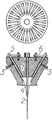
На чертеже изображена схема многоканального электрода, который использовался для регистрации нейронной активности.The drawing shows a diagram of a multi-channel electrode, which was used to register neural activity.
Схема содержит изготовленный из диэлектрического материала (фторопласта) держатель 1, в центральном канале которого находится подвижная игла из вольфрама 2, а в боковых наклонных отверстиях с помощью винтов 3 укреплены микропроводники. Каждый из них представляет собой микропровод 4 в стеклянной изоляции (диаметр токопроводящей жилы 1-3 мкм, толщина изолирующего ее стеклянного покрытия 5-7 мкм), верхнюю часть которого после удаления слоя стекла во фтористоводородной кислоте фиксируют токопроводящим клеем внутри металлического стержня 5 (отрезок инъекционной иглы). Нижние концы всех микропроводников 4 с помощью раствора сахарозы приклеивают к центральной игле 2. Ближние к центру держателя 1 концы токосъемников 6 (ламели микроразъема РГ1Н-1-5) припаяны к микрокабелю, подключенному к входам многоканального усилителя.The circuit contains a holder 1 made of a dielectric material (fluoroplastic), in the central channel of which there is a
Устройство работает следующим образом. После трепанации кости черепа над областью регистрации и удаления участка твердой мозговой оболочки в ткань мозга плавно погружают многоканальный электрод и жидкой пластмассой (Норакрил-100) скрепляют держатель 1 с костью черепа. Спустя 15-20 минут, которые необходимы для растворения сахарозы в ткани мозга, иглу 2 вынимают из центрального отверстия и подключают каждый микропроводник через токосъемник 6 к одному из входов многоканального усилителя. Затем, используя (в зависимости от вида биологического объекта) либо стереотаксический аппарат, либо микроманипулятор, последовательно поднимают каждый из стержней 5 в канале держателя 1 до уровня, обеспечивающего наибольшую амплитуду активного биоэлектрического сигнала на выходе соответствующего канала усилителя. В этом положении каждый стержень окончательно фиксируют микровинтом 3 в канале держателя 1.The device operates as follows. After trepanation of the bone of the skull over the area of registration and removal of the dura mater, the multichannel electrode is gently immersed in the brain tissue and the holder 1 is fastened to the skull bone with liquid plastic (Noracryl-100). After 15-20 minutes, which are necessary for dissolving sucrose in the brain tissue, the
Возможность осуществления изобретения с реализацией указанного назначения подтверждается известностью средств и методов получения устройств.The possibility of carrying out the invention with the implementation of this purpose is confirmed by the well-known means and methods of obtaining devices.
Таким образом, подтверждена возможность осуществления изобретения.Thus, the possibility of carrying out the invention is confirmed.
Техническим результатом изобретения является повышение уровня эффективности нейрофизиологического тестирования за счет увеличения одновременно регистрируемых нейронов головного мозга, появления возможности одновременной микроточечной стимуляции мозга в области локализации функционально маркированных нервных клеток и за счет снижения уровня травматичности мозговой ткани в ходе нейрохирургического вмешательства.The technical result of the invention is to increase the efficiency of neurophysiological testing by increasing simultaneously recorded brain neurons, the possibility of simultaneous micro-point stimulation of the brain in the area of functionally labeled nerve cells and by reducing the level of brain tissue trauma during neurosurgical intervention.
Источники информацииInformation sources
1. V.Tsytsarev, M.Taketani, F.Schottler, Shigeru Tanaka and Masahiko Hara. A new planar multielectrode array: recording from a rat auditory cortex// J. Neural Eng. 3 (2006). 293-298.1. V. Tsytsarev, M. Taketani, F. Schottler, Shigeru Tanaka and Masahiko Hara. A new planar multielectrode array: recording from a rat auditory cortex // J. Neural Eng. 3 (2006). 293-298.
2. Justin С.Williams, Robert L. Rennaker, Daryl R. Kipke. Long-term neural recording characteristics of wire microelectrode arrays implanted in cerebral cortex. Brain Research Protocols. 4 (1999). 303-313.2. Justin C. Williams, Robert L. Rennaker, Daryl R. Kipke. Long-term neural recording characteristics of wire microelectrode arrays implanted in cerebral cortex. Brain Research Protocols. 4 (1999). 303-313.
3. Steven J. Eliades, Xiaoqin Wang. Chronic multi-electrode neural recording in free-roaming monkeys// Journal of Neuroscience Methods. 172 (2008). 201-214.3. Steven J. Eliades, Xiaoqin Wang. Chronic multi-electrode neural recording in free-roaming monkeys // Journal of Neuroscience Methods. 172 (2008). 201-214.
4. J.Hetke, D.Pellinen, D.Anderson. Modular multichannel microelectrode array and methods of making same// Patent USA. WO 2007/042999 A3 (19.04.2007).4. J. Hatke, D. Pellinen, D. Anderson. Modular multichannel microelectrode array and methods of making the same // Patent USA. WO 2007/042999 A3 (04/19/2007).
Claims (1)
Translated fromRussianPriority Applications (1)
| Application Number | Priority Date | Filing Date | Title |
|---|---|---|---|
| RU2009136914/14ARU2421253C1 (en) | 2009-10-07 | 2009-10-07 | Multichannel electrode with independent bundle travel of microconductors |
Applications Claiming Priority (1)
| Application Number | Priority Date | Filing Date | Title |
|---|---|---|---|
| RU2009136914/14ARU2421253C1 (en) | 2009-10-07 | 2009-10-07 | Multichannel electrode with independent bundle travel of microconductors |
Publications (2)
| Publication Number | Publication Date |
|---|---|
| RU2009136914A RU2009136914A (en) | 2011-04-20 |
| RU2421253C1true RU2421253C1 (en) | 2011-06-20 |
Family
ID=44050795
Family Applications (1)
| Application Number | Title | Priority Date | Filing Date |
|---|---|---|---|
| RU2009136914/14ARU2421253C1 (en) | 2009-10-07 | 2009-10-07 | Multichannel electrode with independent bundle travel of microconductors |
Country Status (1)
| Country | Link |
|---|---|
| RU (1) | RU2421253C1 (en) |
Cited By (1)
| Publication number | Priority date | Publication date | Assignee | Title |
|---|---|---|---|---|
| RU2678637C2 (en)* | 2013-10-07 | 2019-01-30 | Конинклейке Филипс Н.В. | Flexible conductive track arrangement and manufacturing method |
Citations (5)
| Publication number | Priority date | Publication date | Assignee | Title |
|---|---|---|---|---|
| US5843148A (en)* | 1996-09-27 | 1998-12-01 | Medtronic, Inc. | High resolution brain stimulation lead and method of use |
| US6343226B1 (en)* | 1999-06-25 | 2002-01-29 | Neurokinetic Aps | Multifunction electrode for neural tissue stimulation |
| US20050004627A1 (en)* | 2001-10-26 | 2005-01-06 | Peter Gibson | Auditory midbrain implant |
| WO2007042999A2 (en)* | 2005-10-07 | 2007-04-19 | Neuronexus Technologies | Modular multichannel microelectrode array and methods of making same |
| RU81075U1 (en)* | 2008-09-26 | 2009-03-10 | Институт физиологии им. И.П. Павлова Российской Академии Наук (ИФРАН) | BIOPOLAR CONCENTRIC MICROELECTRODE (BKE) |
- 2009
- 2009-10-07RURU2009136914/14Apatent/RU2421253C1/ennot_activeIP Right Cessation
Patent Citations (5)
| Publication number | Priority date | Publication date | Assignee | Title |
|---|---|---|---|---|
| US5843148A (en)* | 1996-09-27 | 1998-12-01 | Medtronic, Inc. | High resolution brain stimulation lead and method of use |
| US6343226B1 (en)* | 1999-06-25 | 2002-01-29 | Neurokinetic Aps | Multifunction electrode for neural tissue stimulation |
| US20050004627A1 (en)* | 2001-10-26 | 2005-01-06 | Peter Gibson | Auditory midbrain implant |
| WO2007042999A2 (en)* | 2005-10-07 | 2007-04-19 | Neuronexus Technologies | Modular multichannel microelectrode array and methods of making same |
| RU81075U1 (en)* | 2008-09-26 | 2009-03-10 | Институт физиологии им. И.П. Павлова Российской Академии Наук (ИФРАН) | BIOPOLAR CONCENTRIC MICROELECTRODE (BKE) |
Cited By (2)
| Publication number | Priority date | Publication date | Assignee | Title |
|---|---|---|---|---|
| RU2678637C2 (en)* | 2013-10-07 | 2019-01-30 | Конинклейке Филипс Н.В. | Flexible conductive track arrangement and manufacturing method |
| US10492701B2 (en) | 2013-10-07 | 2019-12-03 | Koninklijke Philips N.V. | Flexible conductive track arrangement and manufacturing method |
Also Published As
| Publication number | Publication date |
|---|---|
| RU2009136914A (en) | 2011-04-20 |
Similar Documents
| Publication | Publication Date | Title |
|---|---|---|
| US7941202B2 (en) | Modular multichannel microelectrode array and methods of making same | |
| CN109171718B (en) | Microneedle Electrode Array Device | |
| Shen et al. | Translational opportunities and challenges of invasive electrodes for neural interfaces | |
| Patel et al. | Chronic in vivo stability assessment of carbon fiber microelectrode arrays | |
| US8170638B2 (en) | MEMS flexible substrate neural probe and method of fabricating same | |
| Guitchounts et al. | A carbon-fiber electrode array for long-term neural recording | |
| Mercanzini et al. | In vivo electrical impedance spectroscopy of tissue reaction to microelectrode arrays | |
| JP5444235B2 (en) | Apparatus and removal module for stimulating biological tissue with microelectrodes and use thereof | |
| Vetter et al. | Chronic neural recording using silicon-substrate microelectrode arrays implanted in cerebral cortex | |
| US20100100152A1 (en) | Electrode system for deep brain stimulation | |
| US20110021943A1 (en) | Neural interface | |
| US20170007824A1 (en) | Minimally invasive splaying microfiber electrode array and methods of fabricating and implanting the same | |
| CN111053554A (en) | Ultramicro flexible linear deep brain electrode | |
| CN103519808B (en) | Multi-channel microelectrode array and manufacturing method thereof | |
| CN105561469A (en) | Implanted multifunctional double-side micro brain electrode array chip | |
| US20230147961A1 (en) | Implantable Transition Micro-Electrodes | |
| CN1973918B (en) | Implantable cluster-stimulating microelectrode arrays in the human nervous system | |
| CN105852855A (en) | Implantable cerebral electrode for measuring cerebral primary visual electrocorticograms in rodents | |
| CN104490385A (en) | Needle type microelectrode array | |
| Richie et al. | Fabrication and Validation of Sub-Cellular Carbon Fiber Electrodes | |
| Borda et al. | Three-dimensional multilayer concentric bipolar electrodes restrict spatial activation in optic nerve stimulation | |
| Ejserholm et al. | ${\mbi {\mu}} $-Foil Polymer Electrode Array for Intracortical Neural Recordings | |
| CN116407129A (en) | An in-body multi-channel independently adjustable electrophysiological recording electrode device and its preparation and implantation method | |
| RU2421253C1 (en) | Multichannel electrode with independent bundle travel of microconductors | |
| Richie et al. | Benchtop carbon fiber microelectrode array fabrication toolkit |
Legal Events
| Date | Code | Title | Description |
|---|---|---|---|
| MM4A | The patent is invalid due to non-payment of fees | Effective date:20141008 |