RU2417045C1 - Visual analyser activation time device - Google Patents
Visual analyser activation time deviceDownload PDFInfo
- Publication number
- RU2417045C1 RU2417045C1RU2009142101/14ARU2009142101ARU2417045C1RU 2417045 C1RU2417045 C1RU 2417045C1RU 2009142101/14 ARU2009142101/14 ARU 2009142101/14ARU 2009142101 ARU2009142101 ARU 2009142101ARU 2417045 C1RU2417045 C1RU 2417045C1
- Authority
- RU
- Russia
- Prior art keywords
- block
- inputs
- adder
- output
- outputs
- Prior art date
Links
Images


Landscapes
- Eye Examination Apparatus (AREA)
Abstract
Description
Translated fromRussianИзобретение относится к медицине и медицинской технике и предназначено для определения времени возбуждения зрительного анализатора человека.The invention relates to medicine and medical equipment and is intended to determine the time of excitation of the human visual analyzer.
Известен трехканальный тахистоскоп для измерения порогового времени, необходимого для узнавания предъявляемых изображений [1]. Данное устройство в центре предэкспозиционного поля проецирует точку фиксации, которую используют в качестве сигнала готовности. Фронты поля экспозиции составляют 1,5-2,0 мс. Время экспозиции варьируют с помощью электронного устройства с минимальным шагом в 1,5 мс.Known three-channel tachistoscope for measuring the threshold time required to recognize the presented images [1]. This device in the center of the pre-exposure field projects a fixation point, which is used as a ready signal. The fronts of the exposure field are 1.5–2.0 ms. Exposure times vary using an electronic device with a minimum step of 1.5 ms.
Недостатком данного тахистоскопа является низкая точность измерения порогового времени узнавания изображений, обусловленная затянутыми фронтами поля экспозиции, составляющими 1,5-2 мс, и минимальным шагом изменения времени экспозиции, равным 1,5 мс.The disadvantage of this tachistoscope is the low accuracy of measuring the threshold time for image recognition, due to the extended edges of the exposure field, comprising 1.5-2 ms, and the minimum step of changing the exposure time equal to 1.5 ms.
Известно устройство для измерения и регистрации на машинный носитель интервалов времени между моментом раздражения и последовательными импульсами реакции нейрона. Устройство содержит генератор опорной частоты, 12-разрядный счетчик, запоминающее устройство, входной узел, схему управления, формирователь адресов, схему индикации и буферный регистр [2].A device is known for measuring and recording on a machine carrier time intervals between the moment of stimulation and successive reaction impulses of a neuron. The device comprises a reference frequency generator, a 12-bit counter, a storage device, an input node, a control circuit, an address driver, an indication circuit, and a buffer register [2].
Недостатком данного устройства является невозможность определения времени возбуждения зрительного анализатора в целом, так как в данном устройстве измеряется время между моментом раздражения и реакции нейрона или группы нейронов. Известно, что при активации мозга один и тот же нейрон может ответить на раздражение как учащением, так и урежением импульсации [3]. При этом обнаружена цикличность колебаний частоты фоновой нейрональной импульсации и установлено, что ответ нейрона зависит от того, в какую фазу цикла попадало раздражение [4]. Кроме того, установлено существование множества различных нейронов со специфическими функциями обработки сигналов [5], поэтому на основе ответа отдельного нейрона или группы нейронов нельзя судить о времени возбуждения зрительного анализатора в целом.The disadvantage of this device is the inability to determine the excitation time of the visual analyzer as a whole, since in this device the time between the moment of irritation and the reaction of a neuron or group of neurons is measured. It is known that when the brain is activated, one and the same neuron can respond to stimulation with both increased and decreased impulses [3]. In this case, the cyclicality of the oscillations of the frequency of the background neuronal impulse was found and it was found that the response of the neuron depends on what phase of the cycle the stimulus entered [4]. In addition, the existence of many different neurons with specific signal processing functions has been established [5]; therefore, based on the response of an individual neuron or group of neurons, one cannot judge the time of excitation of the visual analyzer as a whole.
Наиболее близким по технической сущности к предлагаемому изобретению является устройство для исследования параметров инерционности зрительной системы человека, содержащее пульт управления, источник света, счетчик, блок индикации, генератор секундных импульсов, первый одновибратор, элемент И, генератор миллисекундных импульсов, второй одновибратор с регулируемой длительностью импульса, третий одновибратор и элемент ИЛИ, причем выход элемента И соединен с первым входом счетчика, выход которого соединен с первым входом блока индикации, первый выход пульта управления соединен с первым входом источника света, выход первого одновибратора соединен с вторым входом счетчика, второй вход блока индикации соединен с вторым выходом пульта управления, выход генератора миллисекундных импульсов соединен с первым входом элемента И, выход генератора секундных импульсов соединен со входом первого одновибратора, выход которого соединен с первым входом элемента ИЛИ и с первым входом второго одновибратора с регулируемой длительностью импульса, выход которого соединен со вторым входом элемента И и со входом третьего одновибратора, выход которого соединен со вторым входом элемента ИЛИ, выход которого соединен со вторым входом источника света, третий выход пульта управления соединен со вторым входом второго одновибратора с регулируемой длительностью импульса [6].Closest to the technical nature of the present invention is a device for studying the inertia parameters of the human visual system, comprising a control panel, a light source, a counter, an indicating unit, a second pulse generator, a first one-shot, element I, a millisecond-pulse generator, a second one-shot with an adjustable pulse duration , the third one-shot and the element OR, and the output of the element And is connected to the first input of the counter, the output of which is connected to the first input of the display unit , the first output of the control panel is connected to the first input of the light source, the output of the first one-shot is connected to the second input of the counter, the second input of the display unit is connected to the second output of the control panel, the output of the millisecond pulse generator is connected to the first input of the element And, the output of the second pulse generator is connected to the input the first one-shot, the output of which is connected to the first input of the OR element and to the first input of the second one-shot with an adjustable pulse duration, the output of which is connected to the second input ohm of the AND element and with the input of the third one-shot, the output of which is connected to the second input of the OR element, the output of which is connected with the second input of the light source, the third output of the control panel is connected to the second input of the second one-shot with an adjustable pulse duration [6].
Недостатком устройства является длительность исследования параметров инерционности зрительной системы человека. Это не позволяет использовать устройство при массовых обследованиях или в процессе тестирования методом велоэргометрии с целью оценки степени утомления человека или его функционального состояния.The disadvantage of this device is the duration of the study of the parameters of inertia of the human visual system. This does not allow the use of the device during mass examinations or in the process of testing by bicycle ergometry in order to assess the degree of fatigue of a person or his functional state.
Технический результат предлагаемого устройства заключается в уменьшении времени исследования, благодаря чему оно может применяться при массовых обследованиях или в процессе тестирования методом велоэргометрии с целью оценки степени утомления человека или его функционального состояния.The technical result of the proposed device is to reduce the research time, so that it can be used for mass examinations or in the process of testing by bicycle ergometry in order to assess the degree of fatigue of a person or his functional state.
Технический результат достигается тем, что устройство содержит первый генератор секундных импульсов, второй генератор миллисекундных импульсов, первый-третий одновибраторы, элемент ИЛИ, счетчик и блок индикации, выход первого генератора соединен с входом первого одновибратора, выход которого соединен с входом второго одновибратора, причем новым является то, что дополнительно введены первый-второй мультиплексоры, блок из 10 мультиплексоров, блок из 9 сумматоров, четвертый одновибратор, блок из 10 одновибраторов, блок из 10 формирователей временных интервалов, блок из 11 ключей, блок из 10 элементов ИЛИ, блок из 10 регистров, первый-второй регистры, шифратор, преобразователь двоичного кода в двоично-десятичный и блок из 10 источников света, второй генератор миллисекундных импульсов вырабатывает импульсы с частотой 10 кГц, выход первого одновибратора соединен также с первыми входами блока элементов ИЛИ, вторые входы которого соединены с выходами блока одновибраторов, а выходы - с входами блока источников света, выход второго генератора соединен с первыми входами блока формирователей временных интервалов, вторые входы которого соединены с выходами блока мультиплексоров, третьи входы - с выходом второго одновибратора, а выходы - с входами блока одновибраторов, выход второго одновибратора соединен также с первыми входами блока регистров, вторые входы которого соединены с выходами блока мультиплексоров, а выходы - с первыми входами второго мультиплексора, вторые входы которого соединены с выходами первого регистра, а выходы - с первыми входами второго регистра, второй вход которого соединен с выходом четвертого одновибратора, а выходы - с входами преобразователя кода, выходы которого соединены с входами блока индикации, выходы второго регистра соединены также с первыми входами блока сумматоров и вторыми входами первого мультиплексора блока мультиплексоров, вторые входы второго-десятого мультиплексоров блока мультиплексоров соединены с выходами блока сумматоров, на первые входы блока мультиплексоров подаются двоичные коды, соответствующие числам в десятичном коде 10, 60, 110, 160, 210, 260, 310, 360, 410 и 460, вторые входы блока сумматоров соединены с выходами первого мультиплексора, на первые-вторые входы которого подаются двоичные коды, соответствующие числам в десятичном коде 5 и 1, а третий вход соединен с выходом счетчика, выход первого сумматора блока сумматоров соединен также с первыми входами второго сумматора, выход второго сумматора блока сумматоров соединен также с первыми входами третьего сумматора, выход третьего сумматора блока сумматоров соединен также с первыми входами четвертого сумматора, выход четвертого сумматора блока сумматоров соединен также с первыми входами пятого сумматора, выход пятого сумматора блока сумматоров соединен также с первыми входами шестого сумматора, выход шестого сумматора блока сумматоров соединен также с первыми входами седьмого сумматора, выход седьмого сумматора блока сумматоров соединен также с первыми входами восьмого сумматора, выход восьмого сумматора блока сумматоров соединен также с первыми входами девятого сумматора, выходы блока ключей соединены с входами шифратора и элемента ИЛИ, выходы шифратора соединены с первыми входами первого регистра, выход элемента ИЛИ соединен с входом третьего одновибратора, выход которого соединен с вторым входом первого регистра, входами четвертого одновибратора и счетчика, выход которого соединен также с третьими входами блока мультиплексоров.The technical result is achieved by the fact that the device contains a first generator of second pulses, a second generator of millisecond pulses, a first to third one-shot, an OR element, a counter and a display unit, the output of the first generator is connected to the input of the first one-shot, the output of which is connected to the input of the second one-shot, and new is that the first and second multiplexers, a block of 10 multiplexers, a block of 9 adders, a fourth one-shot, a block of 10 one-shots, a block of 10 formers intervals, a block of 11 keys, a block of 10 OR elements, a block of 10 registers, the first to second registers, an encoder, a binary-to-decimal code converter and a block of 10 light sources, a second millisecond pulse generator generates pulses with a frequency of 10 kHz , the output of the first one-shot is also connected to the first inputs of the block of elements OR, the second inputs of which are connected to the outputs of the block of one-shots, and the outputs to the inputs of the block of light sources, the output of the second generator is connected to the first inputs of the block time intervals, the second inputs of which are connected to the outputs of the unit of multiplexers, the third inputs - to the outputs of the second one-shot, and the outputs - to the inputs of the block of one-shot, the output of the second one-shot is also connected to the first inputs of the block of registers, the second inputs of which are connected to the outputs of the block of multiplexers, and outputs - with the first inputs of the second multiplexer, the second inputs of which are connected to the outputs of the first register, and the outputs - with the first inputs of the second register, the second input of which is connected to the output of the fourth one and the outputs are connected to the inputs of the code converter, the outputs of which are connected to the inputs of the display unit, the outputs of the second register are also connected to the first inputs of the adder block and the second inputs of the first multiplexer of the multiplexer block, the second inputs of the second to tenth multiplexers of the multiplexer block are connected to the outputs of the adder block, binary codes corresponding to the numbers in
Заявляемое устройство благодаря введению первого-второго мультиплексоров, блока из 10 мультиплексоров, блока из 9 сумматоров, четвертого одновибратора, блока из 10 одновибраторов, блока из 10 формирователей временных интервалов, блока из 11 ключей, блока из 10 элементов ИЛИ, блока из 10 регистров, первого-второго регистров, шифратора, преобразователя двоичного кода в двоично-десятичный и блока из 10 источников света позволяет уменьшить время измерения, благодаря чему может применяться при массовых обследованиях или в процессе тестирования методом велоэргометрии с целью оценки степени утомления человека или его функционального состояния.The inventive device due to the introduction of the first or second multiplexers, a block of 10 multiplexers, a block of 9 adders, a fourth one-shot, a block of 10 one-shots, a block of 10 shaper time intervals, a block of 11 keys, a block of 10 OR elements, a block of 10 registers, first-second registers, encoder, binary-to-decimal converter, and a block of 10 light sources can reduce the measurement time, which can be used in mass surveys or in the process of testing House of bicycle ergometry in order to assess the degree of fatigue of a person or his functional state.
Таким образом, заявляемое устройство отличается от известных новым свойством, обусловливающим получение положительного эффекта.Thus, the claimed device differs from the known new property, which determines the receipt of a positive effect.
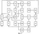
На фиг.1 представлена структурная схема заявляемого устройства, на фиг.2 - схема блока сумматоров с указанием кодов, формируемых на первом этапе измерений.Figure 1 presents a structural diagram of the inventive device, figure 2 is a block diagram of the adders indicating the codes generated at the first stage of measurement.
На фиг.3 представлены источники света блока источников света и соответствующие им ключи блока ключей.Figure 3 presents the light sources of the block of light sources and the corresponding keys of the block of keys.
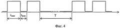
На фиг.4 представлена временная диаграмма последовательности парных световых импульсов, предъявляемых для определения времени возбуждения зрительного анализатора.Figure 4 presents a timing diagram of a sequence of paired light pulses presented to determine the excitation time of the visual analyzer.
На фиг.5 представлены временные диаграммы двух световых импульсов длительностью τимп, разделенных межимпульсным интервалом tмии, и вызываемых ими зрительных ощущений, где:Figure 5 presents the timing diagrams of two light pulses of duration τimp , separated by the interpulse interval t of themission , and the visual sensations caused by them, where:
- фиг.5,а - временная диаграмма двух световых импульсов, разделенных межимпульсным интервалом tмии, вызывающих зрительное ощущение раздельности импульсов;- figure 5, a is a timing chart of two light pulses separated by an interpulse interval t of themission , causing a visual sensation of separation of pulses;
- фиг.5,б - временная диаграмма зрительного ощущения двух световых импульсов, представленных на фиг.5а;- figure 5, b is a timing diagram of the visual sensation of the two light pulses shown in figa;
- фиг.5,в - временная диаграмма двух световых импульсов, разделенных пороговым межимпульсным интервалом tпор, при котором достигается ощущение слияния двух световых импульсов в паре в один;- figure 5, c is a timing diagram of two light pulses separated by a threshold inter-pulse interval tthen , at which the sensation of the merging of two light pulses in a pair into one is achieved;
- фиг.5,г - временная диаграмма зрительного ощущения двух световых импульсов, представленных на фиг.5в;- figure 5, g is a timing diagram of the visual sensation of the two light pulses shown in figv;
- τon - время возбуждения on-системы зрительного анализатора - время суммации on-системы, необходимое для возникновения зрительного ощущения начала стимула, то есть время между моментом воздействия света на сетчатку и моментом возникновения соответствующего зрительного ощущения [7, 8] (фиг.5,б);- τon is the time of on-system excitation of the visual analyzer — the summation time of the on-system is necessary for the visual sensation of the onset of the stimulus to appear, that is, the time between the moment of light exposure on the retina and the moment the corresponding visual sensation occurs [7, 8] (Fig. 5 b);
- τoff - время возбуждения off-системы зрительного анализатора - время суммации off-системы, необходимое для возникновения зрительного ощущения окончания стимула (фиг.5,б).- τoff is the excitation time of the off-system of the visual analyzer is the summation time of the off-system necessary for the visual sensation of the end of the stimulus (Fig. 5, b).
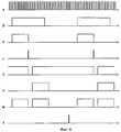
На фиг.6 представлены временные диаграммы работы заявляемого устройства.Figure 6 presents the timing diagrams of the operation of the claimed device.
Заявляемое устройство содержит первый генератор 1 секундных импульсов, второй генератор миллисекундных импульсов, вырабатывающий импульсы с частотой 10 кГц, первый-второй мультиплексоры 3-4, блок 5 из 10 мультиплексоров, блок 6 из первого-девятого 24-32 сумматоров, счетчик 7, первый-четвертый одновибраторы 8-11, блок 12 из 10 одновибраторов, блок 13 из 10 формирователей временных интервалов, блок 14 из 11 ключей, блок 15 из 10 элементов ИЛИ, элемент 16 ИЛИ, блок 17 из 10 регистров, первый-второй регистры 18-19, шифратор 20, преобразователь 21 двоичного кода в двоично-десятичный, блок 22 из 10 источников света и блок 23 индикации.The inventive device contains a first generator of 1 second pulses, a second millisecond pulse generator that generates pulses with a frequency of 10 kHz, the first and second multiplexers 3-4,
Первый 8 одновибратор и блок 12 одновибраторов предназначены для выработки двух световых импульсов длительности 200 мс, второй-четвертый 9-11 одновибраторы - для формирования коротких импульсов. Одновибраторы могут быть выполнены, например, с использованием микросхемы К155АГ1, которая может запускаться как по переднему, так и по заднему фронтам поступающих импульсов, по схеме [9, рис.4.20, с.216].The first 8 single vibrator and
Формирователи временных интервалов блока 13 предназначены для формирования межимпульсных интервалов между световыми импульсами в паре и могут быть выполнены, например, по схеме [10, рис.7.48а, с.265].Shapers of time intervals of
Остальные функциональные узлы структурной схемы общеизвестны или соответствуют прототипу.The remaining functional units of the structural diagram are well known or correspond to the prototype.
Устройство работает следующим образом. При включении питания счетчик 7, регистры блока 17 и регистры 18-19 обнуляются, формирователи временных интервалов блока 13 устанавливаются в режим параллельной записи (цепи не показаны), на первые входы блока 5 подаются двоичные коды, соответствующие числам в десятичном коде 10, 60, 110, 160, 210, 260, 310, 360, 410 и 460, поступающие через мультиплексоры блока 5 соответственно на входы блока 17 и на входы параллельной записи блока 13, на первый-второй входы мультиплексора 3 подаются двоичные коды, соответствующие числам в десятичном коде 5 и 1. Генератор 2 вырабатывает импульсы с частотой 10 КГц, поступающие на счетный вход блока 13 (фиг.6,а), генератор 1 вырабатывает импульсы с частотой 1 Гц (фиг.6,б), поступающие на вход одновибратора 8, который по переднему фронту каждого импульса вырабатывает первый из двух парных импульсов длительностью 200 мс (фиг.6,в). Импульсы с выхода одновибратора 8 поступают на одновибратор 9 и через блок 15 на источники света блока 22 (фиг.6,ж).The device operates as follows. When the power is turned on, the
Одновибратор 9 по заднему фронту импульса с выхода одновибратора 8 вырабатывает короткий импульс (фиг.6,г), который записывает коды с выходов блока 5 в блок 17 регистров и запускает формирователи временных интервалов блока 13, длительность формируемых импульсов отрицательной полярности соответствует кодам на входе и равна 1, 6, 11, 16, 21, 26, 31, 36, 41 и 46 мс (один из импульсов показан на фиг.6,д).The one-
Импульсы с выходов блока 13 поступают на одновибраторы блока 12, которые по окончании импульсов вырабатывают вторые из двух парных импульсов длительностью 200 мс (фиг.6,е), поступающие через блок 15 на источники света блока 22 (фиг.6,ж).The pulses from the outputs of
На первом этапе испытуемый определяет источник света блока 22 с наибольшим номером, для которого ощущает слияние двух световых импульсов в паре в один, и замыкает соответствующий ему ключ блока 14, сигнал с выхода которого поступает на шифратор 20 и элемент 16 ИЛИ. Код замкнутого ключа с выхода шифратора 20 поступает на регистр 18, сигнал с выхода элемента 16 ИЛИ - на одновибратор 10, импульс с выхода которого (фиг.6,з) поступает на одновибратор 11, счетчик 7 и записывает в регистр 18 код замкнутого ключа.At the first stage, the subject determines the light source of
Код замкнутого ключа с выхода регистра 18 поступает на адресные входы мультиплексора 4. Двоичный код N с выхода блока 17, соответствующий длительности межимпульсного интервала источника света с наибольшим номером, для которого испытуемым ощущается слияние двух световых импульсов в паре в один, через мультиплексор 4 поступает на регистр 19, в который записывается импульсом с выхода одновибратора 11. Двоичный код N с выхода регистра 19 поступает на вторые входы первого мультиплексора блока 5 и блок сумматоров 6.The closed key code from the output of the
Импульс с выхода одновибратора 10 увеличивает код на выходе счетчика 7 на единицу, который поступает на адресные входы мультиплексоров блока 5 и мультиплексора 3. Двоичный код, соответствующий числу в десятичном коде 5, с выхода мультиплексора 3 поступает на входы сумматоров блока 6, на выходах которого формируются двоичные коды, соответствующие числам в десятичном коде Р+5, Р+10, Р+15, Р+20, Р+25, Р+30, Р+35, Р+40 и Р+45 (число Р в десятичном коде соответствует числу N в двоичном коде). Коды с выходов сумматоров блока 6 поступают на вторые входы второго-десятого мультиплексоров блока 5, коды с выходов мультиплексоров блока 5 поступают на входы блока 17 и на входы параллельной записи блока 13. Остальная часть схемы работает аналогично тому, как описано выше.The pulse from the output of the one-
На втором этапе испытуемый определяет источник света блока 22 с наибольшим номером, для которого ощущает слияние двух световых импульсов в паре в один, и замыкает соответствующий ему ключ блока 14, сигнал с выхода которого поступает на шифратор 20 и элемент 16 ИЛИ. Код замкнутого ключа с выхода шифратора 20 поступает на регистр 18, сигнал с выхода элемента 16 ИЛИ - на одновибратор 10, импульс с выхода которого (фиг.6,з) поступает на одновибратор И, счетчик 7 и записывает в регистр 18 код замкнутого ключа. Остальная часть схемы работает аналогично тому, как описано выше.At the second stage, the test subject determines the light source of
При этом двоичный код М с выхода блока 17, соответствующий длительности межимпульсного интервала источника света с наибольшим номером, для которого испытуемым ощущается слияние двух световых импульсов в паре в один, через мультиплексор 4 поступает на регистр 19, в который записывается импульсом с выхода одновибратора 11. Двоичный код М с выхода регистра 19 поступает на вторые входы первого мультиплексора блока 5 и блок сумматоров 6.At the same time, the binary code M from the output of
Импульс с выхода одновибратора 10 увеличивает код на выходе счетчика 7 на единицу, который поступает на адресные входы мультиплексоров блока 5 и мультиплексора 3. Двоичный код, соответствующий числу в десятичном коде 1, с выхода мультиплексора 3 поступает на входы сумматоров блока 6, на выходах которого формируются двоичные коды, соответствующие числам в десятичном коде Q+1, Q+2, Q+3, Q+4, Q+5, Q+6, Q+7, Q+8 и Q+9 (число Q в десятичном коде соответствует числу М в двоичном коде). Коды с выходов сумматоров блока 6 поступают на вторые входы второго-десятого мультиплексоров блока 5, коды с выходов мультиплексоров блока 5 поступают на входы блока 17 и на входы параллельной записи блока 13. Остальная часть схемы работает аналогично тому, как описано выше.The pulse from the output of the one-
На третьем этапе испытуемый определяет источник света блока 22 с наибольшим номером, для которого ощущает слияние двух световых импульсов в паре в один, и замыкает соответствующий ему ключ блока 14, сигнал с выхода которого поступает на шифратор 20 и элемент 16 ИЛИ. Код замкнутого ключа с выхода шифратора 20 поступает на регистр 18, сигнал с выхода элемента 16 ИЛИ - на одновибратор 10, импульс с выхода которого (фиг.6,з) поступает на одновибратор 11, счетчик 7 и записывает в регистр 18 код замкнутого ключа. Остальная часть схемы работает аналогично тому, как описано выше. При этом двоичный код с выхода регистра 19, соответствующий длительности межимпульсного интервала источника света с наибольшим номером, для которого испытуемым ощущается слияние двух световых импульсов в паре в один, поступает на преобразователь кода 21, результат преобразования отображается на индикаторах блока 23 индикации.At the third stage, the test subject determines the light source of
После считывания с индикаторов блока 23 индикации значения длительности межимпульсного интервала, принимаемого за значение времени возбуждения зрительного анализатора человека, испытуемый кратковременным замыканием одиннадцатого ключа блока 14 устанавливает устройство в исходное состояние (цепи не показаны).After reading from the indicators of the display unit 23 the value of the duration of the interpulse interval, taken as the value of the excitation time of the human visual analyzer, the person tested by short-circuiting the eleventh key of
Известно, что в зрительном анализаторе on- и off-системы, формирующие соответственно сигнал о появлении и окончании светового стимула, функционируют независимо друг от друга [11, 12], а их динамика сходна [13]. Это позволяет определить время возбуждения зрительного анализатора, то есть on-системы, по равному ему времени возбуждения off-системы.It is known that in the visual analyzer, on- and off-systems, which respectively generate a signal about the appearance and end of a light stimulus, function independently of each other [11, 12], and their dynamics are similar [13]. This allows you to determine the excitation time of the visual analyzer, that is, the on-system, by the equal time of the excitation of the off-system.
При предъявлении испытуемому двух световых импульсов длительностью τимп>τon, разделенных межимпульсным интервалом tмии>tпор(фиг.5,а), off-система зрительного анализатора после окончания первого импульса возбудится и сформирует сигнал, свидетельствующий о его окончании, поэтому у испытуемого возникает субъективное ощущение раздельности двух световых импульсов (фиг.5,б).Upon presentation to the subject of two light pulses with a duration of τimp > τon separated by an interpulse interval tmission > tthen (Fig. 5, a), the off-system of the visual analyzer is excited after the end of the first impulse and generates a signal indicating its end, therefore the subject there is a subjective sensation of separation of two light pulses (Fig.5, b).
При уменьшении длительности межимпульсного интервала между двумя световыми импульсами восприятие зрительных импульсов затрудняется из-за влияния обратной маскировки, заключающейся в ухудшении восприятия первого по времени импульса вследствие предъявления второго импульса в непосредственной пространственно-временной близости с первым, а также прямой маскировки, при которой первый импульс влияет на качество восприятия второго [14]. Поэтому при уменьшении длительности межимпульсного интервала tмии между двумя световыми импульсами до значения tмии=tпор (фиг.5,в) off-система зрительного анализатора после окончания первого импульса не успевает возбудится и сформировать сигнал, свидетельствующий о его окончании, и у испытуемого возникает ощущение субъективного слияния двух световых импульсов в один (фиг.5,г).With a decrease in the duration of the inter-pulse interval between two light pulses, the perception of visual pulses is more difficult due to the influence of reverse masking, which consists in a deterioration in the perception of the first time pulse due to the presentation of the second pulse in the immediate spatio-temporal proximity with the first, as well as direct masking, in which the first pulse affects the quality of perception of the second [14]. Therefore, with a decrease in the duration of the interpulse interval t of themission between two light pulses to the value of tmission = tthen (Fig. 5, c), the off-system of the visual analyzer does not have time to be excited after the end of the first pulse and generate a signal indicating its end, and the subject there is a feeling of subjective fusion of two light pulses into one (Fig. 5, d).
Длительность порогового межимпульсного интервала tпор между двумя световыми импульсами, при которой достигается субъективное ощущение слияния двух световых импульсов в один, определяет пороговое значение времени возбуждения off-системы или равного ему порогового значения времени возбуждения on-системы зрительного анализатора.The duration of the threshold interpulse interval t ofpores between two light pulses, at which a subjective sensation of the fusion of two light pulses into one is achieved, determines the threshold value of the excitation time of the off-system or an equal threshold value of the excitation time of the on-system of the visual analyzer.
Во время ответов на световые стимулы появляется вначале рецептивное поле (РП) нейрона небольшого размера. Затем регистрируемое РП расширяется, после чего ослабляется, фрагментируется и исчезает. Статистическая оценка показала, что исчезновение регистрируемого РП нейрона приходится на период от 100 до 200 мс после появления светового стимула [13]. После исчезновения РП нейронные структуры приходят в исходное состояние и становятся готовыми к восприятию нового стимула [15], поэтому длительность световых импульсов принята равной 200 мс.During responses to light stimuli, the receptive field (RP) of a small neuron appears first. Then, the recorded RP expands, after which it weakens, fragmentes, and disappears. A statistical evaluation showed that the disappearance of the registered RP of the neuron occurs in the period from 100 to 200 ms after the appearance of the light stimulus [13]. After the disappearance of RP, neural structures return to their initial state and become ready to accept a new stimulus [15], therefore, the duration of light pulses is taken to be 200 ms.
Экспериментально установлено, что время возбуждения зрительного анализатора человека находится в пределах от 5 до 19 мс [16], поэтому длительность межимпульсного интервала между двумя световыми импульсами на первом этапе измерений принята с некоторым запасом для первого светодиода блока 22 равной 1 мс, для последнего светодиода - 46 мс. Шаг увеличения длительности межимпульсного интервала между двумя световыми импульсами для последующего диода по сравнению с длительностью межимпульсного интервала предыдущего диода на третьем этапе измерений равен 0,1 мс, так как точность отсчета время возбуждения зрительного анализатора принята равной 0,1 мс [16].It was experimentally established that the excitation time of the human visual analyzer is in the range of 5 to 19 ms [16], therefore, the duration of the interpulse interval between two light pulses at the first measurement stage is taken with a margin of 1 ms for the first LED of
При межстимульном интервале, равном 500 мс, эффекты маскировки отсутствуют или слабо выражены [17]. Для устранения эффекта маскировки последовательность парных световых импульсов повторяется через постоянный временной интервал 1 с.At an interstimulus interval of 500 ms, masking effects are absent or weakly expressed [17]. To eliminate the masking effect, the sequence of paired light pulses is repeated at a constant time interval of 1 s.
Таким образом, заявляемое устройство позволяет уменьшить время исследования, благодаря чему может применяться при массовых обследованиях или в процессе тестирования методом велоэргометрии с целью оценки степени утомления человека или его функционального состояния.Thus, the inventive device allows to reduce the research time, so it can be used for mass examinations or during testing by bicycle ergometry in order to assess the degree of fatigue of a person or his functional condition.
Источники информацииInformation sources
1. Кроль В.М., Таненгольц Л.И. Время узнавания, пороговое время предъявления и длительность маскирования изображений // Физиология человека. - 1976. - Т.2, №4. - С.566-570.1. Krol V.M., Tanengolts L.I. Recognition time, threshold time of presentation and duration of image masking // Human Physiology. - 1976. - T.2, No. 4. - S.566-570.
2. Хабибуллин Р.Д., Перфильев А.Н. Устройства для измерения и регистрации на машинный носитель интервалов времени между моментом раздражения и последовательными импульсами реакции нейрона // Физиол. журнал СССР им.И.М.Сеченова. -1983. - Т.LXIX, №10. - С.1383-1385.2. Khabibullin R. D., Perfilyev A. N. Devices for measuring and recording time intervals between the moment of stimulation and successive reaction impulses of a neuron on a machine carrier // Fiziol. USSR Journal of I.M.Sechenov. -1983. - T.LXIX, No. 10. - S.1383-1385.
3. Кратин Ю.Г., Чукова С.В., Пантелеев С.С., Рыбаков М.В. Мозаичность возбудительных и тормозных процессов в популяциях нейронов коры при реакции активации мозга // Физиол. журнал СССР им. И.М.Сеченова. - 1987. - T.LXXIII, №5. - C.607-617.3. Kratin Yu.G., Chukova S.V., Panteleev S.S., Rybakov M.V. Mosaicism of excitatory and inhibitory processes in populations of cortical neurons during a brain activation reaction // Fiziol. USSR journal them. I.M.Sechenova. - 1987. - T.LXXIII, No. 5. - C.607-617.
4. Лавров В.В. Динамика сверхмедленных колебаний мультинейронной активности и биоэлектрических потенциалов мозга кошки при неподкрепляемом световом раздражении // Физиол. журнал СССР им.И.М.Сеченова. - 1989. - Т.75, №7. - С.890-897.4. Lavrov V.V. Dynamics of super slow oscillations of multineuron activity and bioelectric potentials of the brain of a cat with non-reinforced light stimulation // Fiziol. USSR Journal of I.M.Sechenov. - 1989. - T.75, No. 7. - S.890-897.
5. Шамшинова A.M., Волков В.В. Функциональные методы исследования в офтальмологии: - М.: Медицина, 1999. - 416 с.5. Shamshinova A.M., Volkov VV Functional research methods in ophthalmology: - M .: Medicine, 1999. - 416 p.
6. Патент 2220656, А61В 5/16. Устройство для исследования параметров инерционности зрительной системы человека / В.В.Роженцов, И.В.Петухов (РФ). - Опубл. 10.01.04, Бюл. №1.6. Patent 2220656,
7. Кравков С.В. Глаз и его работа. Психофизиология зрения, гигиена освещения. - 4-е изд., перераб. и доп. - М.-Л.: Изд-во АН СССР, 1950. - 531 с.7. Kravkov S.V. Eye and his work. Psychophysiology of vision, lighting hygiene. - 4th ed., Revised. and add. - M.-L.: Publishing House of the Academy of Sciences of the USSR, 1950 .-- 531 p.
8. Семеновская Е.Н. Электрофизиологические исследования в офтальмологии. - М.: Медгиз, 1963. - 279 с.8. Semenovskaya E.N. Electrophysiological studies in ophthalmology. - M .: Medgiz, 1963 .-- 279 p.
9. Расчет элементов цифровых устройств: Учеб. пособие / Л.Н.Преснухин, Н.В.Воробьев, А.А.Шишкевич; Под ред. Л.Н.Преснухина. - 2-е изд., перераб. и доп. - М.: Высшая школа, 1991. - 526 с.9. Calculation of elements of digital devices: Textbook. allowance / L.N. Presnukhin, N.V. Vorobiev, A.A. Shishkevich; Ed. L.N. Presnukhina. - 2nd ed., Revised. and add. - M.: Higher School, 1991 .-- 526 p.
10. Фролкин В.Т., Попов Л.Н. Импульсные и цифровые устройства: Учеб. пособие для вузов. - М.: Радио и связь, 1992. - 336 с.10. Frolkin V.T., Popov L.N. Pulse and digital devices: Textbook. manual for universities. - M .: Radio and communications, 1992 .-- 336 p.
11. Супин А.Я. Нейронные механизмы зрительного анализа. - М.: Наука, 1974. - 192 с.11. Supin A.Ya. Neural mechanisms of visual analysis. - M .: Nauka, 1974. - 192 p.
12. Глезер В.Д. Зрение и мышление. Изд. 2-е, испр. и доп.- СПб.: Наука, 1993. - 284 с.12. Glezer V.D. Vision and thinking. Ed. 2nd, rev. and additional - St. Petersburg: Nauka, 1993 .-- 284 p.
13. Шевелев И.А. Временная переработка сигналов в зрительной коре // Физиология человека. - 1997. - Т.23, №2. - С.68-79.13. Shevelev I.A. Temporary signal processing in the visual cortex // Human Physiology. - 1997. - T.23, No. 2. - S.68-79.
14. Кропотов Ю.Д., Пономарев В.А. Реакция нейронов и вызванные потенциалы в подкорковых структурах мозга при зрительном опознании. Сообщение IV. Эффект маскировки зрительных стимулов // Физиология человека. - 1987. - Т.13, №4. - С.561-566.14. Kropotov Yu.D., Ponomarev V.A. The reaction of neurons and evoked potentials in the subcortical structures of the brain during visual recognition. Message IV. The effect of masking visual stimuli // Human physiology. - 1987. - T.13, No. 4. - S. 561-566.
15. Подвигин Н.Ф. Динамические свойства нейронных структур зрительной системы. Л.: Наука, 1979. - 158 с.15. Podvigin N.F. Dynamic properties of neural structures of the visual system. L .: Nauka, 1979.- 158 p.
16. Роженцов В.В., Алиев М.Т. Время ощущения зрительного анализатора человека // Вестник Казанского государственного технического университета им. А.Н.Туполева. - 2005. - №3(39). - С.20-23.16. Rozhentsov V.V., Aliev M.T. Sensation time of the human visual analyzer // Bulletin of Kazan State Technical University. A.N. Tupolev. - 2005. - No. 3 (39). - S.20-23.
17. Тароян Н.А., Мямлин В.В., Генкина О.А. Межполушарные функциональные отношения в процессе решения человеком зрительно-пространственной задачи // Физиология человека. - 1992. - Т.18, №2. - С.5-14.17. Taroyan N.A., Myamlin V.V., Genkina O.A. Interhemispheric functional relations in the process of solving a visual-spatial problem by a person // Human Physiology. - 1992. - T.18, No. 2. - S. 5-14.
Claims (1)
Translated fromRussianPriority Applications (1)
| Application Number | Priority Date | Filing Date | Title |
|---|---|---|---|
| RU2009142101/14ARU2417045C1 (en) | 2009-11-16 | 2009-11-16 | Visual analyser activation time device |
Applications Claiming Priority (1)
| Application Number | Priority Date | Filing Date | Title |
|---|---|---|---|
| RU2009142101/14ARU2417045C1 (en) | 2009-11-16 | 2009-11-16 | Visual analyser activation time device |
Publications (1)
| Publication Number | Publication Date |
|---|---|
| RU2417045C1true RU2417045C1 (en) | 2011-04-27 |
Family
ID=44731489
Family Applications (1)
| Application Number | Title | Priority Date | Filing Date |
|---|---|---|---|
| RU2009142101/14ARU2417045C1 (en) | 2009-11-16 | 2009-11-16 | Visual analyser activation time device |
Country Status (1)
| Country | Link |
|---|---|
| RU (1) | RU2417045C1 (en) |
Citations (6)
| Publication number | Priority date | Publication date | Assignee | Title |
|---|---|---|---|---|
| GB1438175A (en)* | 1972-07-15 | 1976-06-03 | Nissan Motor | Device for evaluating mental competence |
| WO2002032309A1 (en)* | 2000-10-16 | 2002-04-25 | Burckhardt Christof W | Apparatus for detecting a retinal or optical nerve disorder |
| RU2195174C1 (en)* | 2001-06-18 | 2002-12-27 | Марийский государственный технический университет | Method for detecting time for human visual persistence |
| RU2220656C1 (en)* | 2002-04-15 | 2004-01-10 | Марийский государственный технический университет | Device for studying human vision system inertia parameters |
| RU2005110160A (en)* | 2005-04-08 | 2006-10-20 | Государственное учреждение "Межотраслевой научно-технический комплекс "Микрохирурги глаза" им. акад. С.Н. Федорова Министерства здравоохранени Российской Федерации" (RU) | METHOD FOR DIAGNOSTIC AND RECOVERY OF VISUAL FUNCTIONS IN PARTIAL ATROPHY OF THE VISUAL NERVE IN CHILDREN |
| RU2329017C1 (en)* | 2006-11-14 | 2008-07-20 | Федеральное государственное учреждение "МОСКОВСКИЙ НАУЧНО-ИССЛЕДОВАТЕЛЬСКИЙ ИНСТИТУТ ГЛАЗНЫХ БОЛЕЗНЕЙ имени ГЕЛЬМГОЛЬЦА ФЕДЕРАЛЬНОГО АГЕНТСТВА ПО ЗДРАВООХРАНЕНИЮ И СОЦИАЛЬНОМУ РАЗВИТИЮ" | Method of diagnostics and functional treatment of myopia and other refraction anomalies |
- 2009
- 2009-11-16RURU2009142101/14Apatent/RU2417045C1/enactive
Patent Citations (6)
| Publication number | Priority date | Publication date | Assignee | Title |
|---|---|---|---|---|
| GB1438175A (en)* | 1972-07-15 | 1976-06-03 | Nissan Motor | Device for evaluating mental competence |
| WO2002032309A1 (en)* | 2000-10-16 | 2002-04-25 | Burckhardt Christof W | Apparatus for detecting a retinal or optical nerve disorder |
| RU2195174C1 (en)* | 2001-06-18 | 2002-12-27 | Марийский государственный технический университет | Method for detecting time for human visual persistence |
| RU2220656C1 (en)* | 2002-04-15 | 2004-01-10 | Марийский государственный технический университет | Device for studying human vision system inertia parameters |
| RU2005110160A (en)* | 2005-04-08 | 2006-10-20 | Государственное учреждение "Межотраслевой научно-технический комплекс "Микрохирурги глаза" им. акад. С.Н. Федорова Министерства здравоохранени Российской Федерации" (RU) | METHOD FOR DIAGNOSTIC AND RECOVERY OF VISUAL FUNCTIONS IN PARTIAL ATROPHY OF THE VISUAL NERVE IN CHILDREN |
| RU2329017C1 (en)* | 2006-11-14 | 2008-07-20 | Федеральное государственное учреждение "МОСКОВСКИЙ НАУЧНО-ИССЛЕДОВАТЕЛЬСКИЙ ИНСТИТУТ ГЛАЗНЫХ БОЛЕЗНЕЙ имени ГЕЛЬМГОЛЬЦА ФЕДЕРАЛЬНОГО АГЕНТСТВА ПО ЗДРАВООХРАНЕНИЮ И СОЦИАЛЬНОМУ РАЗВИТИЮ" | Method of diagnostics and functional treatment of myopia and other refraction anomalies |
Non-Patent Citations (1)
| Title |
|---|
| ГОЛУБЦОВ К.В. и др. Применение электрического тока в диагностике и лечении патологии зрительного нерва и сетчатки. Клиническая офтальмология, №2, 07.05.2001, с.66. САЙКОВСКАЯ Л.Ф. Результаты исследования частотных характеристик зрительной системы с использованием автоматизированного прибора. Бионика Интеллекта, 2008, №2, с.173-176. ШАМШИНОВА A.M. и др. Функциональные методы исследования в офтальмологии. - М., 2004, с.98-115.* |
Similar Documents
| Publication | Publication Date | Title |
|---|---|---|
| DeWind et al. | Numerical encoding in early visual cortex | |
| US3901215A (en) | Method of testing the senses and cognition of subjects | |
| Getzmann et al. | Does age increase auditory distraction? Electrophysiological correlates of high and low performance in seniors | |
| RU2220656C1 (en) | Device for studying human vision system inertia parameters | |
| RU2195174C1 (en) | Method for detecting time for human visual persistence | |
| US3780724A (en) | SENSATION-COGNITION COMPUTER EMPLOYING {37 t{38 {11 TEST CALCULATIONS | |
| Bharadwaj et al. | An exploratory study of visual sequential processing in children with cochlear implants | |
| Momin et al. | Visual attention, mental stress and gender: A study using physiological signals | |
| RU2428110C2 (en) | System and method for diagnostics of brain stem malfunction | |
| Boylan et al. | Feature-based attentional amplitude modulations of the steady-state visual evoked potentials reflect blood oxygen level dependent changes in feature-sensitive visual areas | |
| RU2301623C1 (en) | Device for investigating parameteres of inertia of human vision system | |
| RU2417045C1 (en) | Visual analyser activation time device | |
| RU2271742C1 (en) | Device for finding time of excitation of human visual analyzer | |
| RU2302200C1 (en) | Device for measuring time of excitation of human vision analyzer | |
| Crema et al. | Embedded platform-based system for early detection of Alzheimer disease through transcranial magnetic stimulation | |
| RU2231293C1 (en) | Method for determining stimulation time for human visual analyzer | |
| RU2314032C1 (en) | Device for studying time of inertia of human visual system | |
| KR20110023426A (en) | Parameter-selective neurofeedback method, neurofeedback device using the same and neurofeedback system using the same | |
| RU2332159C1 (en) | Method of defining response time of human vision system | |
| RU2109482C1 (en) | Method and device for diagnosing average induced brain potential | |
| RU2283030C1 (en) | Device for determination of human visual system's labile state | |
| RU2369327C1 (en) | Device for analysing parametres of human visual system sluggishness | |
| RU2269293C1 (en) | Device for measuring time of perception of visual information | |
| RU2252701C1 (en) | Method for determining human vision system persistence time | |
| RU89360U1 (en) | DEVICE FOR RESEARCH TIME OF INERTIATION OF HUMAN VISUAL SYSTEM |