RU2412725C2 - Air-conducting device in form of laryngeal mask - Google Patents
Air-conducting device in form of laryngeal maskDownload PDFInfo
- Publication number
- RU2412725C2 RU2412725C2RU2007147022/14ARU2007147022ARU2412725C2RU 2412725 C2RU2412725 C2RU 2412725C2RU 2007147022/14 ARU2007147022/14 ARU 2007147022/14ARU 2007147022 ARU2007147022 ARU 2007147022ARU 2412725 C2RU2412725 C2RU 2412725C2
- Authority
- RU
- Russia
- Prior art keywords
- mask
- tube
- air
- patient
- cuff
- Prior art date
Links
- 239000000463materialSubstances0.000claimsabstractdescription30
- 210000003238esophagusAnatomy0.000claimsabstractdescription11
- 230000002093peripheral effectEffects0.000claimsabstractdescription7
- 210000004704glottisAnatomy0.000claimsdescription3
- 229920003023plasticPolymers0.000claimsdescription2
- 239000004033plasticSubstances0.000claimsdescription2
- 230000000903blocking effectEffects0.000abstractdescription4
- 208000003443UnconsciousnessDiseases0.000abstractdescription3
- 230000000241respiratory effectEffects0.000abstractdescription3
- 239000000126substanceSubstances0.000abstractdescription2
- 230000008030eliminationEffects0.000abstract2
- 238000003379elimination reactionMethods0.000abstract2
- 239000003814drugSubstances0.000abstract1
- 230000000694effectsEffects0.000abstract1
- XLYOFNOQVPJJNP-UHFFFAOYSA-NwaterSubstancesOXLYOFNOQVPJJNP-UHFFFAOYSA-N0.000abstract1
- 229920000915polyvinyl chloridePolymers0.000description14
- 239000004800polyvinyl chlorideSubstances0.000description14
- 238000003780insertionMethods0.000description13
- 230000037431insertionEffects0.000description13
- 238000004519manufacturing processMethods0.000description8
- 210000002409epiglottisAnatomy0.000description5
- 210000004072lungAnatomy0.000description5
- 238000000926separation methodMethods0.000description5
- 239000003292glueSubstances0.000description4
- 238000000465mouldingMethods0.000description4
- 210000003800pharynxAnatomy0.000description4
- 210000003437tracheaAnatomy0.000description4
- 238000013461designMethods0.000description3
- 238000006073displacement reactionMethods0.000description3
- 239000012530fluidSubstances0.000description3
- 238000009434installationMethods0.000description3
- 238000000034methodMethods0.000description3
- 239000007787solidSubstances0.000description3
- 210000002784stomachAnatomy0.000description3
- 238000009423ventilationMethods0.000description3
- 210000003484anatomyAnatomy0.000description2
- 238000005452bendingMethods0.000description2
- 230000015572biosynthetic processEffects0.000description2
- 239000012634fragmentSubstances0.000description2
- 238000002627tracheal intubationMethods0.000description2
- 230000007704transitionEffects0.000description2
- 206010011224CoughDiseases0.000description1
- 239000004944Liquid Silicone RubberSubstances0.000description1
- 230000001154acute effectEffects0.000description1
- 239000000853adhesiveSubstances0.000description1
- 230000001070adhesive effectEffects0.000description1
- 238000013459approachMethods0.000description1
- 230000004888barrier functionEffects0.000description1
- 238000000071blow mouldingMethods0.000description1
- 238000007664blowingMethods0.000description1
- 238000006243chemical reactionMethods0.000description1
- 238000005056compactionMethods0.000description1
- 230000006835compressionEffects0.000description1
- 238000007906compressionMethods0.000description1
- 238000005336crackingMethods0.000description1
- 230000002496gastric effectEffects0.000description1
- 210000003026hypopharynxAnatomy0.000description1
- 238000002347injectionMethods0.000description1
- 239000007924injectionSubstances0.000description1
- 230000003993interactionEffects0.000description1
- 210000000867larynxAnatomy0.000description1
- 239000007788liquidSubstances0.000description1
- 210000004400mucous membraneAnatomy0.000description1
- 230000007935neutral effectEffects0.000description1
- 238000006213oxygenation reactionMethods0.000description1
- 238000012794pre-harvestingMethods0.000description1
- 230000002265preventionEffects0.000description1
- 238000011084recoveryMethods0.000description1
- 210000002345respiratory systemAnatomy0.000description1
- 230000028327secretionEffects0.000description1
- 229920002379silicone rubberPolymers0.000description1
- 238000012546transferMethods0.000description1
- 230000000472traumatic effectEffects0.000description1
- 238000013022ventingMethods0.000description1
- 210000004916vomitAnatomy0.000description1
- 230000008673vomitingEffects0.000description1
Images


Classifications
- A—HUMAN NECESSITIES
- A61—MEDICAL OR VETERINARY SCIENCE; HYGIENE
- A61M—DEVICES FOR INTRODUCING MEDIA INTO, OR ONTO, THE BODY; DEVICES FOR TRANSDUCING BODY MEDIA OR FOR TAKING MEDIA FROM THE BODY; DEVICES FOR PRODUCING OR ENDING SLEEP OR STUPOR
- A61M16/00—Devices for influencing the respiratory system of patients by gas treatment, e.g. ventilators; Tracheal tubes
- A61M16/04—Tracheal tubes
- A61M16/0434—Cuffs
- A61M16/045—Cuffs with cuffs partially or completely inflated by the respiratory gas
- A—HUMAN NECESSITIES
- A61—MEDICAL OR VETERINARY SCIENCE; HYGIENE
- A61M—DEVICES FOR INTRODUCING MEDIA INTO, OR ONTO, THE BODY; DEVICES FOR TRANSDUCING BODY MEDIA OR FOR TAKING MEDIA FROM THE BODY; DEVICES FOR PRODUCING OR ENDING SLEEP OR STUPOR
- A61M16/00—Devices for influencing the respiratory system of patients by gas treatment, e.g. ventilators; Tracheal tubes
- A61M16/04—Tracheal tubes
- A61M16/0402—Special features for tracheal tubes not otherwise provided for
- A61M16/0409—Special features for tracheal tubes not otherwise provided for with mean for closing the oesophagus
- A—HUMAN NECESSITIES
- A61—MEDICAL OR VETERINARY SCIENCE; HYGIENE
- A61M—DEVICES FOR INTRODUCING MEDIA INTO, OR ONTO, THE BODY; DEVICES FOR TRANSDUCING BODY MEDIA OR FOR TAKING MEDIA FROM THE BODY; DEVICES FOR PRODUCING OR ENDING SLEEP OR STUPOR
- A61M16/00—Devices for influencing the respiratory system of patients by gas treatment, e.g. ventilators; Tracheal tubes
- A61M16/04—Tracheal tubes
- A61M16/0402—Special features for tracheal tubes not otherwise provided for
- A61M16/0415—Special features for tracheal tubes not otherwise provided for with access means to the stomach
- A—HUMAN NECESSITIES
- A61—MEDICAL OR VETERINARY SCIENCE; HYGIENE
- A61M—DEVICES FOR INTRODUCING MEDIA INTO, OR ONTO, THE BODY; DEVICES FOR TRANSDUCING BODY MEDIA OR FOR TAKING MEDIA FROM THE BODY; DEVICES FOR PRODUCING OR ENDING SLEEP OR STUPOR
- A61M16/00—Devices for influencing the respiratory system of patients by gas treatment, e.g. ventilators; Tracheal tubes
- A61M16/04—Tracheal tubes
- A61M16/0434—Cuffs
- A61M16/0443—Special cuff-wall materials
- A—HUMAN NECESSITIES
- A61—MEDICAL OR VETERINARY SCIENCE; HYGIENE
- A61M—DEVICES FOR INTRODUCING MEDIA INTO, OR ONTO, THE BODY; DEVICES FOR TRANSDUCING BODY MEDIA OR FOR TAKING MEDIA FROM THE BODY; DEVICES FOR PRODUCING OR ENDING SLEEP OR STUPOR
- A61M16/00—Devices for influencing the respiratory system of patients by gas treatment, e.g. ventilators; Tracheal tubes
- A61M16/04—Tracheal tubes
- A61M16/0434—Cuffs
- A61M16/0445—Special cuff forms, e.g. undulated
- A61M16/0447—Bell, canopy or umbrella shaped
- A—HUMAN NECESSITIES
- A61—MEDICAL OR VETERINARY SCIENCE; HYGIENE
- A61M—DEVICES FOR INTRODUCING MEDIA INTO, OR ONTO, THE BODY; DEVICES FOR TRANSDUCING BODY MEDIA OR FOR TAKING MEDIA FROM THE BODY; DEVICES FOR PRODUCING OR ENDING SLEEP OR STUPOR
- A61M16/00—Devices for influencing the respiratory system of patients by gas treatment, e.g. ventilators; Tracheal tubes
- A61M16/04—Tracheal tubes
- A61M16/0463—Tracheal tubes combined with suction tubes, catheters or the like; Outside connections
- A—HUMAN NECESSITIES
- A61—MEDICAL OR VETERINARY SCIENCE; HYGIENE
- A61M—DEVICES FOR INTRODUCING MEDIA INTO, OR ONTO, THE BODY; DEVICES FOR TRANSDUCING BODY MEDIA OR FOR TAKING MEDIA FROM THE BODY; DEVICES FOR PRODUCING OR ENDING SLEEP OR STUPOR
- A61M16/00—Devices for influencing the respiratory system of patients by gas treatment, e.g. ventilators; Tracheal tubes
- A61M16/08—Bellows; Connecting tubes ; Water traps; Patient circuits
- A61M16/0816—Joints or connectors
- A—HUMAN NECESSITIES
- A61—MEDICAL OR VETERINARY SCIENCE; HYGIENE
- A61M—DEVICES FOR INTRODUCING MEDIA INTO, OR ONTO, THE BODY; DEVICES FOR TRANSDUCING BODY MEDIA OR FOR TAKING MEDIA FROM THE BODY; DEVICES FOR PRODUCING OR ENDING SLEEP OR STUPOR
- A61M16/00—Devices for influencing the respiratory system of patients by gas treatment, e.g. ventilators; Tracheal tubes
- A61M16/08—Bellows; Connecting tubes ; Water traps; Patient circuits
- A61M16/0875—Connecting tubes
- A—HUMAN NECESSITIES
- A61—MEDICAL OR VETERINARY SCIENCE; HYGIENE
- A61M—DEVICES FOR INTRODUCING MEDIA INTO, OR ONTO, THE BODY; DEVICES FOR TRANSDUCING BODY MEDIA OR FOR TAKING MEDIA FROM THE BODY; DEVICES FOR PRODUCING OR ENDING SLEEP OR STUPOR
- A61M16/00—Devices for influencing the respiratory system of patients by gas treatment, e.g. ventilators; Tracheal tubes
- A61M16/04—Tracheal tubes
- A61M16/0488—Mouthpieces; Means for guiding, securing or introducing the tubes
- A61M16/049—Mouthpieces
- A61M16/0493—Mouthpieces with means for protecting the tube from damage caused by the patient's teeth, e.g. bite block
Landscapes
- Health & Medical Sciences (AREA)
- Pulmonology (AREA)
- Life Sciences & Earth Sciences (AREA)
- Public Health (AREA)
- Anesthesiology (AREA)
- Biomedical Technology (AREA)
- Heart & Thoracic Surgery (AREA)
- Hematology (AREA)
- Emergency Medicine (AREA)
- Animal Behavior & Ethology (AREA)
- General Health & Medical Sciences (AREA)
- Engineering & Computer Science (AREA)
- Veterinary Medicine (AREA)
- Media Introduction/Drainage Providing Device (AREA)
- External Artificial Organs (AREA)
- Respiratory Apparatuses And Protective Means (AREA)
- Prostheses (AREA)
- Orthopedics, Nursing, And Contraception (AREA)
- Instructional Devices (AREA)
Abstract
Description
Translated fromRussianОбласть техники, к которой относится изобретениеFIELD OF THE INVENTION
Изобретение относится к воздуховодному устройству в виде ларингеальной маски (к ларингеальному масочному воздуховоду).The invention relates to an airway device in the form of a laryngeal mask (to a laryngeal mask duct).
Уровень техникиState of the art
Ларингеальная маска представляет собой хорошо известное приспособление, полезное для обеспечения дыхательных путей у пациентов, которые находятся в бессознательном состоянии. Из многочисленных публикаций, описывающих такие устройства, можно указать на патент США № 4509514. Ларингеальные маски применялись в течение многих лет, представляя альтернативу более старой, лучше известной эндотрахеальной трубке. По меньшей мере, в течение семидесяти лет эндотрахеальные трубки, содержащие длинный гибкий шланг с надувным баллоном на его дистальном конце, использовались для установления дыхательных путей у потерявших сознание пациентов. В процессе использования дистальный конец эндотрахеальной трубки вводят пациенту через рот в трахею (дыхательное горло). После установки маски в заданное положение баллон надувают, формируя таким образом изолирующее уплотнение внутренней поверхности трахеи. Затем для вентилирования легких пациента к проксимальному концу трубки можно подать воздух при повышенном давлении. Кроме своей главной функции, указанное уплотнение, сформированное между баллоном и внутренней поверхностью трахеи, защищает легкие от нежелательной аспирации (например, предотвращает засасывание рвотных масс, выделяемых из желудка, в легкие пациента).Laryngeal mask is a well-known device that is useful for providing the respiratory tract in patients who are unconscious. Of the many publications describing such devices, US Pat. No. 4,509,514 can be mentioned. Laryngeal masks have been used for many years, presenting an alternative to the older, better known endotracheal tube. For at least seventy years, endotracheal tubes containing a long flexible hose with an inflatable balloon at its distal end have been used to establish airways in unconscious patients. During use, the distal end of the endotracheal tube is administered to the patient through the mouth into the trachea (respiratory throat). After installing the mask in a predetermined position, the balloon is inflated, thereby forming an insulating seal on the inner surface of the trachea. Then, air can be supplied at elevated pressure to ventilate the patient’s lungs to the proximal end of the tube. In addition to its main function, this seal, formed between the balloon and the inner surface of the trachea, protects the lungs from unwanted aspiration (for example, prevents the vomit released from the stomach into the lungs of the patient).
Несмотря на свою высокую эффективность, эндотрахеальные трубки имеют несколько существенных негативных свойств. Так, принципиальным недостатком является сложность введения трубки пациенту надлежащим образом. Эта процедура требует высокой квалификации персонала. К тому же, даже при соблюдении указанного условия, введение эндотрахеальной трубки иногда затруднено или вообще невозможно. В ряде случаев затруднения такого рода заканчивались трагически и приводили к смерти пациента вследствие невозможности достаточно быстро установить ему воздуховод. Кроме того, для введения эндотрахеальной трубки, как правило, приходится манипулировать головой и шеей пациента, а также принудительным образом широко раскрыть ему челюсти. Из-за таких вынужденных манипуляций введение указанной трубки пациенту становится затруднительным или нежелательным, поскольку пациент может повредить шею.Despite its high efficiency, endotracheal tubes have several significant negative properties. So, a fundamental drawback is the difficulty of introducing the tube to the patient properly. This procedure requires highly qualified personnel. In addition, even under the specified conditions, the introduction of the endotracheal tube is sometimes difficult or even impossible. In some cases, difficulties of this kind ended tragically and led to the death of the patient due to the inability to quickly install an air duct for him. In addition, for the introduction of the endotracheal tube, as a rule, you have to manipulate the patient’s head and neck, and also forcefully open his jaw. Due to such forced manipulations, the introduction of the specified tube to the patient becomes difficult or undesirable, since the patient may damage the neck.
В отличие от эндотрахеальной трубки введение ларингеальной маски пациенту, т. е. установка воздуховода, осуществляется относительно легко. Кроме того, такая маска представляет собой "неприхотливое" устройство в том смысле, что даже при неправильном введении тенденция установления воздуховода сохранится. Таким образом, ларингеальную маску часто рассматривают как устройство "спасения жизни". При этом ее можно ввести посредством только относительно небольшого количества манипуляций, касающихся головы, шеи и челюстей пациента. Далее, указанная маска обеспечивает вентилирование легких пациента, не требуя для этого контакта с чувствительной внутренней поверхностью трахеи, а размер установленного воздуховода обычно значительно превышает аналогичный параметр эндотрахеальной трубки. К тому же по сравнению с эндотрахеальными трубками ларингеальная маска в меньшей степени вызывает кашель. Вследствие указанных преимуществ ларингеальная маска в последние годы получила широкое применение.Unlike the endotracheal tube, the introduction of a laryngeal mask to the patient, i.e., the installation of the duct, is relatively easy. In addition, such a mask is an “unpretentious” device in the sense that even with improper insertion, the tendency to establish an air duct will continue. Thus, a laryngeal mask is often considered as a “life saving” device. However, it can be entered through only a relatively small number of manipulations relating to the head, neck and jaws of the patient. Further, this mask provides ventilation of the patient’s lungs, without requiring contact with the sensitive inner surface of the trachea, and the size of the installed duct usually significantly exceeds the similar parameter of the endotracheal tube. In addition, compared to endotracheal tubes, the laryngeal mask causes coughing to a lesser extent. Due to these advantages, the laryngeal mask has been widely used in recent years.
В патентах США №№ 5303697 и 6079409 описаны примеры известных устройств, тип которых можно определить как "воздуховодное устройство в виде интубационной ларингеальной маски". Интубационное устройство полезно также для облегчения введения эндотрахеальной трубки, т. к. после установки пациенту оно может выполнять функцию направляющей при последующем введении указанной трубки. Применение воздуховодного устройства в виде ларингеальной маски в таком варианте облегчает процедуру, обычно трактуемую по отношению к эндотрахеальной трубке как "введение вслепую". Для введения пациенту интубационной маски требуются только небольшие смещения его головы, шеи и челюстей. Эндотрахеальную трубку можно вводить сразу после установки маски, причем для этого фактически не требуется дополнительных смещений пациента. Таким образом, указанная ситуация существенно отличается от варианта, когда для введения эндотрахеальной трубки без помощи интубационной ларингеальной маски приходится производить существенные перемещения головы, шеи и челюстей пациента.In US patent No. 5303697 and 6079409 described examples of known devices, the type of which can be defined as "airway device in the form of an endotracheal laryngeal mask." The endotracheal device is also useful for facilitating the insertion of the endotracheal tube, since after installation it can serve as a guide for the patient after the subsequent insertion of the tube. The use of an airway device in the form of a laryngeal mask in this embodiment facilitates the procedure, which is usually interpreted in relation to the endotracheal tube as “blind insertion”. To introduce an intubation mask to a patient, only small displacements of his head, neck and jaws are required. The endotracheal tube can be inserted immediately after the installation of the mask, and this does not actually require additional displacements of the patient. Thus, this situation differs significantly from the option when, for the introduction of the endotracheal tube without the help of the endotracheal laryngeal mask, significant movements of the patient's head, neck and jaws have to be performed.
Кроме того, указанные устройства позволяют провести введение одной рукой, причем при любом положении оператора, не смещая голову и шею пациента с нейтральной позиции, а также осуществить установку устройства на требуемое место без введения пальцев в рот пациента. Наконец, есть основания полагать, что указанные устройства уникальны в том смысле, что, являясь согласно своей основной функции воздуховодами, они во время попыток интубации позволяют осуществлять непрерывный вентиляционный контроль и оксигенацию пациента. Тем самым уменьшается вероятность десатурации.In addition, these devices allow the introduction of one-handed operation, and at any position of the operator, without moving the patient’s head and neck from a neutral position, and also install the device in the desired place without putting fingers into the patient’s mouth. Finally, there is reason to believe that these devices are unique in the sense that, being air ducts according to their main function, they allow continuous ventilation control and oxygenation of the patient during intubation attempts. This reduces the likelihood of desaturation.
Примеры устройств с искусственными воздуховодами описанного типа приведены в патентах США №№ 4509514, 5249571, 5282464, 5297547, 5303697, а также в UK 2205499. Примеры подобных устройств с дополнительным техническим обеспечением для дренажного опорожнения желудка приведены в патентах США №№4995388 (см. фиг.7-10), 5241956 и 5355879.Examples of devices with artificial ducts of the described type are shown in US Pat. 7-10), 5241956 and 5355879.
В общем случае воздуховодные устройства в виде ларингеальной маски должны обеспечить наличие воздуховодной трубки с таким поперечным сечением, которое гарантировало бы достаточную вентиляцию легких. Конструкции, предназначенные для дренирования желудка, отличались относительно сложными внутренними соединительными элементами, причем их поперечные сечения рассчитывались, исходя из условий работы в трудных ситуациях, в которых в удаляемых желудочных выделениях могут присутствовать твердые субстанции. В результате наличие отверстия для опорожнения желудка, которое расположено у дистального конца маски и пригодно для прямого взаимодействия с гипофаринксом (гортанной частью глотки), приводило в случае таких масок к тенденции увеличения объема и чрезмерной жесткости, а это затрудняет введение маски надлежащим образом. Более того, чрезмерные объем и жесткость находятся в противоречии с требованием дистальной гибкости устройства во время его введения при воспроизведении кривизны задней поверхности горла пациента таким образом, чтобы надежно избежать травмирующего соприкосновения с надгортанником и другими естественными структурами глотки.In the general case, airway devices in the form of a laryngeal mask should ensure the presence of an airway tube with such a cross section that would guarantee adequate ventilation of the lungs. Designs designed for drainage of the stomach differed in relatively complex internal connecting elements, and their cross sections were calculated based on working conditions in difficult situations in which solid substances may be present in the removed gastric secretions. As a result, the presence of a hole for emptying the stomach, which is located at the distal end of the mask and is suitable for direct interaction with the hypopharynx (the laryngeal part of the pharynx), led in the case of such masks to a tendency to increase volume and excessive stiffness, and this makes it difficult to introduce the mask properly. Moreover, excessive volume and stiffness are in conflict with the requirement for distal flexibility of the device during its insertion when reproducing the curvature of the posterior throat of the patient in such a way as to reliably avoid traumatic contact with the epiglottis and other natural structures of the pharynx.
Практический опыт выявил много проблем, связанных со всеми известными типами рассматриваемого устройства. Например, в некоторых из них предпринята попытка посредством барьеров и других подобных приспособлений, расположенных поперек выхода воздуховода, предотвратить его перекрывание анатомическими элементами пациента, такими как надгортанник. Хотя во многих ситуациях такие устройства функционируют удовлетворительно, их изготовление может оказаться более сложным, а при применении эксплуатационные качества устройств могут отклоняться от нормы. В особенности это относится к устройствам, сформированным не из обычного в таких случаях жидкого силиконового каучука (ЖСК), а из более жестких материалов типа ПВХ (поливинилхлорида).Practical experience has revealed many problems associated with all known types of the device in question. For example, in some of them an attempt was made, through barriers and other similar devices located across the outlet of the duct, to prevent its overlapping by the patient's anatomical elements, such as the epiglottis. Although in many situations such devices function satisfactorily, their manufacture may be more complicated, and when applied, the performance of the devices may deviate from the norm. This applies in particular to devices formed not from liquid silicone rubber (HSC), which is usual in such cases, but from more rigid materials such as PVC (polyvinyl chloride).
Как правило, устройства из таких материалов, как ПВХ, предпочтительны, т.к. их изготовление обходится дешевле. С экономической точки зрения эти изделия можно рекомендовать в качестве устройств "одноразового применения". Однако по сравнению с ЖСК для ПВХ и его адгезивов характерны отличия в свойствах материала (например, повышенная твердость по дюрометру), от которых зависит функционирование устройств при их применении. В частности, было показано, что для данного объема воздуха по сравнению с сопоставимой манжетой из ПВХ манжета из ЖСК вытянется до большего размера. Такая повышенная эластичность позволяет ей обеспечить в анатомическом плане улучшенное изолирующее уплотнение при пониженном давлении на слизистую оболочку. Чтобы перекрыть требуемый зазор манжетой из ПВХ, приходится уменьшать толщину ее стенок. Однако недостатком такой манжеты при выпускании из нее воздуха (сдувании) и подготовке к введению будет недостаточная ответная гибкость, т.к. перенос усилия введения через воздуховодную трубку к дистальной оконечности манжеты не может быть погашен адекватным образом. Посредством выпуска воздуха толщину манжетного блока необходимо свести до уровня, на котором сохраняется гибкость, т. е. противодействие опусканию надгортанника, но в то же время толщина стенки манжеты, составляющая 0,4 мм или менее, создает удовлетворительное изолирующее уплотнение. А в том случае, когда задние стенки масок, а также их манжеты изготовлены из ПВХ, факт обратной пропорциональности повышенной твердости ПВХ по дюрометру относительно гибкости устройства (гистерезис) означает, что по сравнению с изделием из ЖСК ухудшается гибкость такого устройства в терминах реакции, а также восстановления после деформации.As a rule, devices made of materials such as PVC are preferred since their manufacture is cheaper. From an economic point of view, these products can be recommended as “disposable” devices. However, compared with HLC, PVC and its adhesives are characterized by differences in the properties of the material (for example, increased hardness by durometer), on which the operation of the devices depends on their use. In particular, it was shown that for a given volume of air, in comparison with a comparable cuff made of PVC, the cuff made of HSS extends to a larger size. Such increased elasticity allows it to provide anatomically improved insulating compaction with reduced pressure on the mucous membrane. To cover the required gap with a PVC cuff, it is necessary to reduce the thickness of its walls. However, the disadvantage of such a cuff when releasing air from it (blowing off) and preparing for the introduction will be insufficient reciprocal flexibility, since the transfer of the insertion force through the air tube to the distal extremity of the cuff cannot be adequately extinguished. By venting the air, the thickness of the cuff block must be reduced to a level at which flexibility remains, i.e., counteraction to lowering the epiglottis, but at the same time, the cuff wall thickness of 0.4 mm or less creates a satisfactory insulating seal. And in the case when the back walls of the masks, as well as their cuffs are made of PVC, the fact that the increased hardness of the PVC by the durometer is inversely proportional to the flexibility of the device (hysteresis) means that, in comparison with the product from HLC, the flexibility of such a device in terms of reaction is worsened, and also recovery after deformation.
Перечисленные проблемы в особой степени обостряются в случае устройств, содержащих канал для дренирования пищевода. Как упоминалось выше, для любого такого устройства, причем независимо от материала, из которого оно сформировано, само по себе добавление указанного средства резко усложняет изготовление устройства, а также может повлиять на эксплуатационные качества устройств, такие как легкость введения, формирование изолирующего уплотнения и предотвращение инсуффляции. Эти проблемы могут обостриться еще больше при применении ПВХ или других материалов с подобными свойствами. Например, для квалифицированного специалиста будет понятно, что в плане изготовления особо трудную проблему представляет необходимость обеспечить наличие дренажной трубки, изолированной от воздуховода, которая должна проходить через надувную манжету. В плане воздействия на функциональные свойства наличие указанной трубки может вызвать неприемлемое увеличение жесткости оконечной зоны маски, а также перекрывание/сужение воздушного канала.These problems are particularly exacerbated in the case of devices containing a channel for drainage of the esophagus. As mentioned above, for any such device, regardless of the material from which it is formed, the mere addition of the indicated means greatly complicates the manufacture of the device and can also affect the performance of the devices, such as ease of insertion, formation of an insulating seal and prevention of insufflation . These problems can be exacerbated by the use of PVC or other materials with similar properties. For example, for a qualified specialist it will be clear that in terms of manufacturing, a particularly difficult problem is the need to ensure the presence of a drainage tube isolated from the duct, which must pass through the inflatable cuff. In terms of affecting the functional properties, the presence of this tube can cause an unacceptable increase in the rigidity of the end zone of the mask, as well as the overlap / narrowing of the air channel.
Раскрытие изобретенияDisclosure of invention
Согласно изобретению предлагается воздуховодное устройство в виде ларингеальной маски, предназначенное для введения пациенту, чтобы обеспечить воздушный канал к отверстию его гортани (к так называемой голосовой щели). Указанное устройство содержит воздуховодную трубку с прикрепленной к ней маской, при этом маска состоит из корпуса, имеющего дистальный и проксимальный концы, и периферийной надувной манжеты (называемой также манжеткой). Маска определяет выпускную зону для газа и прикреплена к воздуховодной трубке с целью обеспечения возможности течения газа между маской и трубкой. Кроме того, устройство содержит средство дренирования пищевода, образующее дренажный канал между входным участком у дистального конца и выходным отверстием, расположенным, когда устройство введено пациенту и установлено в заданное положение, снаружи относительно пациента. Дренажный канал состоит из секции внутри воздуховодной трубки и секции внутри маски, сформированной в материале корпуса маски, как единое целое с корпусом. Таким образом, как можно заключить из сказанного, изобретение направлено на решение проблем, возникающих из необходимости формирования канала для дренирования пищевода и связанных с эксплуатационными качествами устройства и его изготовлением.According to the invention, an airway device in the form of a laryngeal mask is intended for administration to a patient in order to provide an air channel to the opening of his larynx (to the so-called glottis). The specified device contains an air tube with a mask attached to it, while the mask consists of a housing having distal and proximal ends, and a peripheral inflatable cuff (also called cuff). The mask defines the gas outlet and is attached to the air tube to allow gas to flow between the mask and the tube. In addition, the device includes a means of drainage of the esophagus, forming a drainage channel between the inlet at the distal end and the outlet located when the device is introduced to the patient and installed in a predetermined position, outside the patient. The drainage channel consists of a section inside the air tube and a section inside the mask formed in the material of the mask body as a unit with the body. Thus, as can be concluded from the foregoing, the invention is aimed at solving problems arising from the need to form a channel for drainage of the esophagus and associated with the performance of the device and its manufacture.
Предпочтительно, чтобы дренажный канал был вытянут, по существу, вдоль центральной части корпуса маски от дистального конца до проксимального конца корпуса, обеспечивая прямой и короткий проточный маршрут для жидкостей и твердых частиц.Preferably, the drainage channel is elongated substantially along the central portion of the mask body from the distal end to the proximal end of the body, providing a direct and short flow path for liquids and solids.
Корпус маски может содержать пластину, имеющую так называемые дорсальную ("тыльную") и вентральную ("переднюю") стороны. Дорсальная сторона, по существу, гладкая и выпуклая по своей ширине, а на вентральной стороне пластины сформирован выступающий из нее дренажный канал. В результате образуется гладкий дорсальный профиль, облегчающий введение устройства, обеспечивающий пациенту комфорт и сводящий к минимуму отношение размера устройства в направлении от дорсальной стороны к вентральной. Это дополнительно облегчает введение.The mask body may contain a plate having the so-called dorsal ("back") and ventral ("front") sides. The dorsal side is essentially smooth and convex in width, and a drainage channel protruding from it is formed on the ventral side of the plate. As a result, a smooth dorsal profile is formed, facilitating the insertion of the device, providing patient comfort and minimizing the size ratio of the device in the direction from the dorsal to the ventral side. This further facilitates the introduction.
В предпочтительном варианте осуществления изобретения дренажный канал имеет концевую часть, выступающую за дистальный участок корпуса маски. Предусмотрена возможность заключить указанную концевую часть в оболочку, сформированную с ней в виде единого целого, причем концевая часть должна иметь выход из оболочки. Предпочтительно, чтобы эта оболочка была образована выступающей частью материала входного участка и была надувной. В оптимальном варианте она надувается газом из манжеты. Оболочка и манжета образуют единое изолирующее уплотнение, в котором имеется зона поступления газа из манжеты к оболочке. Желательно при этом, чтобы данная зона включала в себя переходный участок манжеты.In a preferred embodiment, the drainage channel has an end portion protruding beyond the distal portion of the mask body. It is possible to enclose the specified end part in a shell formed with it in a single unit, and the end part must have a way out of the shell. Preferably, this shell was formed by the protruding part of the material of the input section and was inflatable. In the best case, it is inflated with gas from the cuff. The shell and cuff form a single insulating seal, in which there is a zone of gas supply from the cuff to the shell. At the same time, this zone should include a transitional section of the cuff.
Концевая часть может содержать средство, предотвращающее ее сплющивание под воздействием повышенного давления воздуха внутри оболочки. Данное средство может содержать одну или несколько поддерживающих перемычек, сформированных в виде единого целого с концевой частью, причем одна или каждая из перемычек может выступать из концевой части, по существу, перпендикулярно к ней.The end portion may contain means to prevent it from collapsing under the influence of increased air pressure inside the shell. This tool may contain one or more supporting jumpers, formed as a whole with the end part, moreover, one or each of the jumpers can protrude from the end part, essentially perpendicular to it.
В предпочтительном варианте материал маски представляет собой пластик, например, с твердостью 50А по Шору, а твердость материала воздуховодной трубки равна 90А по Шору.In a preferred embodiment, the material of the mask is plastic, for example, with a hardness of 50A Shore, and the hardness of the material of the air tube is equal to 90A Shore.
Краткое описание чертежейBrief Description of the Drawings
Далее изобретение будет описано в виде примера со ссылками на прилагаемые чертежи, из которыхThe invention will now be described by way of example with reference to the accompanying drawings, of which
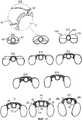
фиг.1 на виде сзади (с дорсальной стороны) представляет повернутое на три четверти перспективное изображение устройства согласно изобретению,figure 1 in the rear view (from the dorsal side) is a three-quarter perspective view of the device according to the invention,
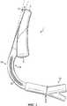
фиг.2 представляет устройство, показанное на фиг.1, на виде с правой стороны,figure 2 represents the device shown in figure 1, in a view from the right side,
фиг.3 представляет устройство, показанное на фиг.1, на виде сзади,figure 3 represents the device shown in figure 1, in a rear view,
фиг.4 представляет устройство, показанное на фиг.1, на виде спереди (с вентральной стороны),figure 4 represents the device shown in figure 1, in front view (from the ventral side),
фиг.4а на виде спереди представляет другой вариант осуществления устройства согласно изобретению,figa in front view represents another embodiment of a device according to the invention,
фиг.5 представляет устройство, показанное на фиг.1, на виде с торца от проксимального конца устройства по направлению к его дистальному концу,figure 5 represents the device shown in figure 1, in an end view from the proximal end of the device towards its distal end,
фиг.6 представляет устройство, показанное на фиг.1, на виде с торца от дистального конца маски по направлению к ее проксимальному концу,6 represents the device shown in figure 1, in an end view from the distal end of the mask towards its proximal end,
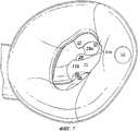
фиг.7 представляет увеличенное изображение маски устройства, показанного на фиг.1,Fig.7 is an enlarged image of the mask of the device shown in Fig.1,
фиг.8 представляет устройство, показанное на фиг.4а, на виде сзади,Fig.8 represents the device shown in figa, in rear view,
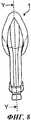
фиг.9 представляет устройство, показанное на фиг.8, в продольном сечении плоскостью Y-Y,Fig.9 represents the device shown in Fig.8, in longitudinal section by a plane Y-Y,
фиг.10 представляет увеличенное изображение устройства, показанного на фиг.4а, на виде сбоку,figure 10 is an enlarged image of the device shown in figa, in side view,
фиг.11А-11К представляют устройство, показанное на фиг.10, в поперечных сечениях плоскостями А-А - К-К,figa-11K represent the device shown in figure 10, in cross sections by planes aa - kk,
на фиг.12 устройство согласно изобретению показано в перспективном изображении на виде сзади с пространственным разделением компонентов,on Fig the device according to the invention is shown in a perspective image in a rear view with a spatial separation of the components,
на фиг.13 устройство согласно изобретению показано в перспективном изображении на виде спереди с пространственным разделением компонентов,in Fig.13 the device according to the invention is shown in a perspective image in a front view with a spatial separation of the components,
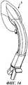
фиг.14 на виде сзади представляет повернутое на три четверти перспективное изображение варианта устройства согласно изобретению,FIG. 14 is a rear view showing a three-quarter perspective view of an embodiment of a device according to the invention,
фиг.15 представляет устройство, показанное на фиг.14, на виде с правой стороны,Fig.15 represents the device shown in Fig.14, in a view from the right side,
фиг.16 представляет устройство, показанное на фиг.14, на виде сзади,Fig.16 represents the device shown in Fig.14, in a rear view,
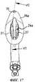
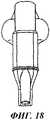
фиг.17 представляет устройство, показанное на фиг.14, на виде спереди,Fig.17 represents the device shown in Fig.14, in front view,
фиг.18 представляет устройство, показанное на фиг.14, на виде с торца от проксимального конца маски по направлению к ее дистальному концу,Fig represents the device shown in Fig, in the end view from the proximal end of the mask towards its distal end,
фиг.19 представляет устройство, показанное на фиг.14, на виде с торца от дистального конца маски по направлению к ее проксимальному концу,Fig.19 represents the device shown in Fig.14, in the end view from the distal end of the mask towards its proximal end,
фиг.20 на виде сзади представляет дополнительно повернутое на три четверти перспективное изображение варианта устройства, показанного на фиг.14,FIG. 20 in a rear view is an additional perspective view of a variant of the device shown in FIG.
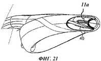
фиг.21 представляет устройство, показанное на фиг.20, в разрезе плоскостью СС-СС,Fig.21 represents the device shown in Fig.20, in the context of the plane CC-SS,
фиг.22 представляет устройство, показанное на фиг.17, в разрезе плоскостью VC-VC,Fig.22 represents the device shown in Fig.17, in the context of the plane VC-VC,
фиг.23 представляет фрагмент показанного на фиг.14 устройства на виде с его проксимального конца иFig.23 is a fragment shown in Fig.14 of the device in a view from its proximal end and
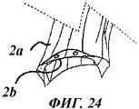
фиг.24 представляет другой фрагмент показанного на фиг.14 устройства на виде с его дистального конца.Fig. 24 is another fragment of the device shown in Fig. 14 in a view from its distal end.
Осуществление изобретенияThe implementation of the invention
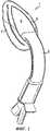
На представленных фиг.1-24 показано воздуховодное устройство 1 в виде ларингеальной маски, предназначенное для введения пациенту, чтобы обеспечить воздушный канал к его голосовой щели. Указанное устройство содержит воздуховодную трубку 2 с прикрепленной к ней маской 3, при этом маска состоит из корпуса с задней пластиной 4, имеющего дистальный и проксимальный концы 5 и 6 соответственно, и периферийной надувной манжеты 7. Маска определяет выпускную зону 8 для газа и прикреплена к воздуховодной трубке с целью обеспечения возможности течения газа между указанным отверстием и трубкой 2. Кроме того, устройство содержит средство 10 дренирования пищевода, образующее дренажный канал, соединяющий входное отверстие 12 у дистального конца и выходное отверстие 13, находящееся снаружи относительно пациента при введении устройства 5 пациенту с установкой в заданное положение. Указанный дренажный канал состоит из секции (дренажной трубки 11) внутри маски и секции (дренажной трубки 41) внутри воздуховодной трубки, причем первая из названных секций целиком сформирована в материале задней пластины 4 корпуса.On the presented figures 1-24 shows the airway device 1 in the form of a laryngeal mask, intended for administration to the patient to provide an air channel to his glottis. The specified device contains an
Как можно видеть из чертежей, устройство 1 внешне отчасти похоже на известные устройства. Имеется в виду, что его основные части, т.е. воздуховодная трубка 2 и маска 3, состоящая из корпуса с задней пластиной 4 и манжеты 7, входят в состав если не всех, то, во всяком случае, большинства воздуховодных устройств типа ларингеальной маски.As can be seen from the drawings, the device 1 externally partially resembles known devices. It is understood that its main parts, i.e. the
Для наглядности описания целесообразно дать цифровые обозначения отдельным зонам устройства 1 (см. фиг.2-6). Таким образом, указанное устройство имеет дорсальную сторону 14, вентральную сторону 15, проксимальный конец 16 (расположенный ближе к оператору, чем к пациенту), дистальный конец 17, а также правую и левую стороны 18 и 19 соответственно.For clarity, it is advisable to give digital designations to the individual zones of the device 1 (see Fig.2-6). Thus, this device has a
В иллюстрируемых вариантах осуществления воздуховодная трубка 2 состоит из относительно жесткого ПВХ-материала, такого как материал марки Colorite PVC с твердостью 90А по Шору. Указанный материал отформован в виде изогнутой детали, кривизна которой соответствует требованиям анатомии. Трубка 2 в какой-то степени эластична, т. е. после изгиба она будет восстанавливать свою исходную форму. Несмотря на способность трубки упруго деформироваться таким образом, жесткость ее достаточна, чтобы выполнять функцию рукоятки и направляющей, способствуя введению устройства 1 пациенту. В отличие от многих известных устройств, в данном варианте осуществления изобретения поперечное сечение воздуховодной трубки 2 не круглое. Вместо этого оно сжато в дорсальном/вентральном направлении, что способствует правильному введению устройства, помогает предотвратить перекручивание и содействует удобному для пациента расположению, т. к. форма данной трубки в типичном случае воспроизводит геометрию естественного дыхательного канала. В рассматриваемом варианте осуществления каждая из сторон 18, 19 трубки 2 имеет канавку (выемку) 20, сформированную на большей части длины трубки между проксимальным и дистальным концами. Указанные канавки оказывают дополнительную помощь в предотвращении сплющивания или перекручивания трубки.In the illustrated embodiments, the
На внутренней стороне воздуховодной трубки 2 канавки 20 образуют выступы, ориентированные вдоль внутренних поверхностей сторон 18 и 19.On the inner side of the
На фиг.13 устройство 1 представлено с пространственным разделением компонентов, причем можно видеть, что воздуховодная трубка 2 имеет расширяющийся дистальный конец 22, поверхности 22а которого расположены так, чтобы трубку можно было удобным образом прикрепить к маске 3 посредством наружного приформовывания маски на трубку. Таким образом, при формировании устройства 1 сама трубка 2 может выполнять функцию предварительной заготовки, что существенно упрощает его изготовление. Особого обсуждения заслуживает дорсальная поверхность 23 трубки, к которой приформовывается маска (см. фиг.13). Она расположена у расширяющегося дистального конца 22 и по форме представляет собой плоский ровный участок, расположенный между наружной дорсальной поверхностью 2а и внутренней дорсальной поверхностью 2b (см. фиг.24) дорсальной стенки 2с. Возможен вариант, в котором в поверхности 23 выполнены сквозные отверстия 2d, позволяющие зафиксировать на трубке 2 приформовываемую заднюю пластину 4, как это будет описано далее. Указанная особенность помогает гарантировать надежное соединение между различающимися по своим свойствам материалами, формирующими трубку 2 и маску 3.In Fig.13, the device 1 is shown with a spatial separation of the components, and it can be seen that the
Следующей особенностью воздуховодной трубки 2 является наличие дренажной трубки 41 для дренирования пищевода. Она размещена во внутреннем объеме трубки 2, проходя по ее оси от одного конца до другого. В данном варианте осуществления дренажная трубка 41 находится в контакте с внутренней поверхностью 2b дорсальной стенки 2с воздуховодной трубки 2 и ограничена на каждой стороне приподнятыми гладкими стенками (не показаны), формирующими неглубокий канал, через который она проходит.Another feature of the
Проксимальный конец воздуховодной трубки 2 снабжен соединительным компонентом 42 (см., например, фиг.12 и 13, а также иллюстрацию в сечении на фиг.9), предназначенным для присоединения устройства 1 к системам дренирования и подачи газа (не показаны). Указанный компонент (коннектор) состоит из корпуса 43, фиксирующей детали 44 (как возможный вариант) и замыкающего элемента 45. Корпус 43 и фиксирующая деталь 44 по форме и размеру соответствуют внутренней конфигурации проксимального конца трубки 2, т. е. входят в него без зазора. Корпус 43 имеет фланец 46, ориентированный перпендикулярно корпусу и на одном из участков своей наружной поверхности переходящий в лапку 47. Замыкающий элемент 45 прикреплен к корпусу 43 соединительного компонента с помощью клея (или какого-либо другого пригодного в данном случае средства), нанесенного на фланец 46. Указанный замыкающий элемент снабжен основным и вспомогательным патрубками (соответственно 48 и 49), каждый из которых ведет в общую полость 50 у дистального конца замыкающего элемента, в месте прикрепления его к корпусу 43. Через вспомогательный патрубок 49, отделенный от внутреннего объема воздуховодной трубки 2, проходит насквозь дренажная трубка 41.The proximal end of the
Маска 3 состоит из двух частей, а именно из корпуса с задней (несущей) пластиной и периферийной манжеты 7.The
В данных вариантах осуществления изобретения задняя пластина 4 изготовлена посредством формования из материала Vythene PVC+PU, имеющего твердость 50А по Шору. По сравнению с материалом воздуховодной трубки 2 указанный материал существенно мягче и обладает большей способностью к деформации.In these embodiments, the
Как показано на фиг.23, на задней пластине 4 сформован фасонный участок, имеющий, в целом, овальную форму, если рассматривать его с дорсального или вентрального направлений. Указанный участок имеет гладкую дорсальную поверхность 24, фигурную вентральную поверхность 24а (см. фиг.17), проксимальный соединительный участок 24b и дистальную оконечность 61.As shown in FIG. 23, a shaped portion having a generally oval shape is formed on the
Дорсальная поверхность 24 выполнена выпуклой в поперечном направлении (по ширине), причем ее кривизна соответствует кривизне дорсальной поверхности воздуховодной трубки 2. В продольном направлении поверхность 24 также является выпуклой, причем ее выпуклая часть, имеющая постоянный изгиб, начинается у соединительного участка 24b и заканчивается у дистальной оконечности 61 корпуса маски. В результате в собранном устройстве 1 указанная оконечность смещена в вентральном направлении относительно дистального конца воздуховодной трубки. Указанное смещение составляет приблизительно 20 мм (примерно 10°), чтобы кривизна маски соответствовала анатомии пациента. Это смещение схематично показано на фиг.2, где оно обозначено символом X. При введении устройства пациенту указанное смещение оконечности 61 помогает маске "повернуть за угол" в процессе ее введения.The dorsal surface 24 is convex in the transverse direction (in width), and its curvature corresponds to the curvature of the dorsal surface of the
Более наглядно элементы, сформованные в виде единой детали на задней пластине 4, можно рассмотреть при наблюдении с вентральной стороны (см. фиг.4, 7, 12, 17). Точная форма вентральной поверхности 24а указанной пластины специально показана в сечениях на фиг. 11А-11К и (в увеличенном масштабе) в перспективном изображении на фиг.7. Как видно из фиг.12, где устройство изображено с пространственным разделением компонентов, выпуклость дорсальной поверхности 24 пластины 4 является зеркальным отражением соответствующей вогнутости на ее вентральной стороне. Таким образом, вентральная поверхность 24а образует неглубокий удлиненный канал, сужающийся к дистальной оконечности 61 и ограниченный боковыми стенками 26. Указанные стенки имеют соответствующим образом сформированные и ориентированные в продольном направлении выгнутые наружные поверхности 25. Каждая боковая стенка 26 вытянута в указанном направлении, по существу, по всей длине задней пластины 4 от проксимального соединительного участка 24b по направлению к дистальной оконечности 61. Кроме того, каждая боковая стенка 26 имеет выпуклую внутреннюю поверхность 28, но, вместо того чтобы завершиться перпендикулярно по отношению к дну канала, изогнутые части каждой стенки имеют продолжение, при этом стенки изогнуты в обратном направлении над каналом и упираются в перемычки 27. ориентированные внутрь (см. фиг.7 и 11). Внутренние поверхности 28 боковых стенок 26 изогнуты вниз, формируя дно канала, но не пересекаются, т.к. основание (дно) канала разделено на две части сформованной в виде единого целого секцией средства 10 дренирования пищевода, ориентированной в продольном направлении и представляющей собой дренажную трубку 11. Дренажная трубка 11 расположена по всей длине основания (дна) канала от соединительного участка 24b до дистальной оконечности 61. Таким образом, можно видеть, что канал на своей внутренней поверхности имеет три прохода, ориентированных в продольном направлении, а именно два прохода 28а, открытых снаружи и являющихся в собранном устройстве 1 вспомогательными проходами для газа, и расположенную по центру дренажную трубку 11, образующую перемычку между ними.More clearly, the elements formed in the form of a single part on the
При более детальном рассмотрении дренажной трубки 11 видно, что она имеет диаметр, достаточный для того, чтобы участок 11а ее верхней стенки, т.е. часть стенки, расположенной дальше от дна канала, находился примерно на том же уровне, что и ориентированные внутрь перемычки 27 боковых стенок 26. Более того, участок 11а стенки сам имеет направленные наружу перемычки 30, сходящиеся в виде конуса по направлению к соответствующим сходящимся кромкам перемычек 27, но не пересекающиеся с ними. Таким образом, перемычки 27, 30 и верхняя поверхность 11b участка 11а верхней стенки дренажной трубки 11 в совокупности образуют поверхность 11с (схематично показанную на фиг.11 пунктирной линией), ниже уровня которой проходят все три названных прохода.A closer look at the
На фиг.7 показано, что, в отличие от дренажной трубки 11, проходящей по всей длине пластины 4 от ее проксимального соединительного участка 24b до дистальной оконечности 61, протяженность проходов 28а ограничена приблизительно половиной длины указанной пластины. Дно 31 этих проходов плавно изгибается вверх по мере их приближения к оконечности 61 пластины до тех пор, пока не достигнет уровня, приблизительно равного уровню перемычек 27 и 30. В варианте осуществления изобретения, представленном на фиг. 4а, эти проходы углублены с целью формирования выемок 31 b.7 shows that, in contrast to the
Как показано на фиг.12 и 21-23, дренажная трубка 11 проходит по направлению к дистальной оконечности 61, доходя до отверстия 12. Таким образом, концевая часть 11е дренажной трубки 11 выступает за конец задней пластины 4. Указанная часть снабжена дорсально расположенным участком 11а, отходящим в обе стороны от концевой части 11е, а также вокруг нее, формируя оболочку 36а, охватывающуюAs shown in FIGS. 12 and 21-23, the
концевую часть 11е и расположенную по ее периметру. Оболочка 36а прикреплена к дистальному концу дренажной трубки 11 по периметру 12а входного отверстия 12 (см. фиг.22). Она сформирована в виде единого целого в материале пластины 4 у дистальной оконечности 61 и полностью окружает указанное отверстие, отходя от его периметра. При этом стык между оболочкой и входным отверстием заглажен. Как проиллюстрировано на чертежах, протяженность оболочки в вентральном направлении ограничена в большей степени, чем в дорсальном. Протяженность в дорсальном направлении составляет приблизительно половину протяженности пластины 4 к проксимальному концу. Из представленных на фиг.11 изображений устройства в сечениях плоскостями А-А и В-В можно видеть, что дренажная трубка 11 удерживается на своих правой и левой сторонах, а также на дорсальной поверхности перпендикулярно выступающими перемычками 62. Они сформированы в виде единого целого и расположены между входным отверстием 12 и зоной, в которой концевая часть 11е пересекается с объемом задней пластины 4. В проиллюстрированном варианте осуществления дорсальные перемычки 62 отходят, по существу, перпендикулярно от дренажной трубки. Однако в предпочтительной версии они могут отходить в ту или другую сторону под углом менее 90°.the end portion 11e and located along its perimeter. The
Вторым компонентом маски 3 является периферийная манжета 7. В данном варианте осуществления изобретения она изготовлена из ПВХ посредством выдувного формования и имеет форму, по существу, эллиптического надувного кольца. Указанное кольцо имеет центральное отверстие 7а, относительно более толстый проксимальный конец 37, снабженный входом 38 для надувания, и относительно более тонкий дистальный конец 7b, сходящийся к "клинообразному" профилю 39. Как видно, в частности, из изображений устройства с пространственным разделением компонентов на фиг.12 и 13, манжета 7 целиком сформирована в виде единой детали. Клинообразный профиль имеет такую конфигурацию, в которой отношение площадей дорсальной и вентральной сторон выбрано превышающим единицу. В результате в спущенном (сдутом) состоянии дистальный конец 7b манжеты будет изгибаться в направлении от дорсальной стороны к вентральной.The second component of the
В собранном устройстве 1 дренажная трубка 41 вставлена в воздуховодную трубку 2 таким образом, чтобы она выступала из проксимального конца 16 устройства. Соединительный компонент 42 прикреплен к воздуховодной трубке 2 посредством ввода его корпуса 43 и фиксирующей детали 44 в проксимальный конец 16 данной трубки. Указанные детали имеют посадку с натягом, причем их можно закрепить клеем. Замыкающий элемент 45 прикреплен к корпусу 43 соединительного компонента через фланец 46, так что дренажная трубка 41 проходит во вспомогательный патрубок 49, оканчиваясь у его входа или рядом с ним. Таким образом, как можно видеть, в системе протекания текучих сред вспомогательный патрубок 49 соединен только с дренажной трубкой 41, а основной патрубок 48 - только с внутренним объемом воздуховодной трубки 2.In the assembled device 1, the
Указанная трубка удобным образом прикреплена к задней пластине 4 посредством приформовывания пластины на уже сформированную воздуховодную трубку 2 (соединительный участок 24b задней пластины 4 приформовывается на дорсальную дугу трубки, см. фиг.13). Надежному прикреплению способствуют поверхности 22а, 23, обеспечивающие увеличенную площадь поверхности, на которую происходит приформовывание, а также сквозные отверстия 2d, в которые может продавиться материал указанной пластины. Дренажная трубка 41 герметичным для текучей среды образом присоединена к сформованной в виде единого целого дренажной трубке 11, как это показано на фиг.13 стрелкой Z.Said tube is conveniently attached to the
Манжета 7 связана с задней пластиной 4, как показано на фиг.12 и 13, посредством введения ее клинообразного дистального конца 7b в оболочку 36а у дистальной оконечности 61 пластины. При этом поверхность клиновидного профиля 39 сопрягается с внутренней поверхностью 36b оболочки, а внутренние периферийные секции манжеты - с выгнутыми наружными поверхностями 25 боковых стенок 26 задней пластины. Манжета 7 вмонтирована в оболочку таким образом, чтобы пространство между ними было непроницаемым для воздуха, причем в данном варианте осуществления манжета имеет переходный участок 40 (см. фиг.21 и 22), соединяющий манжету 7 и оболочку 36а в единый объем для текучей среды. В результате в добавление к надуванию самой манжеты можно надуть воздухом и соответствующее пространство в оболочке. Однако указанный переходный участок не занимает все расстояние по направлению к дистальной оконечности манжеты, тем самым не давая давлению, индуцируемому надуванием, блокировать отверстие 12. Проксимальная дорсальная поверхность манжеты присоединена к вентральной дуге дистального конца 22 воздуховодной трубки 2.The
Таким образом, важным моментом представляется тот факт, что, в отличие от предыдущих устройств, использующих в своей конструкции каналы для дренирования пищевода, в данном изобретении такой дренажный канал (в виде дренажной трубки 11) не проходит через манжету 7, что упрощает изготовление устройства. Далее, в предшествующих устройствах, в которых дренажный канал пронизывает манжету, необходимо надежно закрепить манжету по периметру дренажной трубки у дистальной оконечности. Такое закрепление, например посредством клея, может вызвать отверждение указанной оконечности и помешать сплющиванию дренажной трубки в сдутом плоском состоянии устройства (такое сплющивание крайне желательно, т. к. оно помогает маске легко обогнуть анатомические изгибы). Кроме того, изгиб дренажной трубки под острым углом относительно места соединения с манжетой был бы очень чувствителен к растрескиванию. В данном изобретении указанные проблемы отсутствуют, поскольку дренажная трубка 11 сформована в виде единого целого с оболочкой 36а, которая фактически формирует у дистальной оконечности манжеты вторую (вспомогательную) манжету.Thus, an important point is the fact that, in contrast to previous devices that use channels for drainage of the esophagus in their design, in this invention such a drainage channel (in the form of a drainage tube 11) does not pass through the
Важным моментом является то, что воздуховод устройства 1, представляющий собой проход, через который газ подается пациенту, сформирован внутренним объемом воздуховодной трубки 2, оканчивающимся у ее расширенного дистального конца 22. Указанный конец вместе с задней пластиной 4 и манжетой 7 определяет выпускную зону 8 для газа, проходящего из воздуховодной трубки 2 в маску 3. Эта зона 8 охватывает три маршрута для газа, через которые газ может попасть в маску, а именно основной проход 8а (см. фиг.6) и два вспомогательных прохода 28а.An important point is that the airway of the device 1, which is the passage through which gas is supplied to the patient, is formed by the internal volume of the
При проведении рабочей процедуры устройство 1 в сдутом состоянии вводят пациенту обычным для устройств такого типа образом. Как отмечалось выше, относительная жесткость воздуховодной трубки 2 дает возможность оператору зажать ее в руке и использовать для направления устройства при введении пациенту. С другой стороны, относительно более мягкий и податливый материал задней пластины позволяет маске легче деформироваться, т.е. пройти участок введения, не нанося анатомических повреждений, и вернуться в свою оптимальную форму, гарантируя образование хорошего изолирующего уплотнения на самом дальнем отрезке введения. Вентральное смещение дистальной оконечности 61 корпуса относительно стыка между задней пластиной 4 и воздуховодной трубкой 2 дополнительно облегчает введение, т.к. тем самым указанная оконечность находится под оптимальным углом относительно анатомического изгиба, преодолеваемого на пути введения. В устройствах, сформированных не из часто применяемого ЖСК, а из относительно жестких материалов типа ПВХ, указанные признаки имеют особо важное значение в плане облегчения введения и обеспечения улучшенного изолирующего уплотнения.During the working procedure, the device 1 in a deflated state is administered to the patient in the usual way for devices of this type. As noted above, the relative stiffness of the
Из особенностей приформованной задней пластины 4 можно заключить, что проблемы предшествующих конструкций, вызванные наличием отдельной дренажной трубки, закрепленной на месте клеем, и связанные с жесткостью маски и трудностью изготовления, можно уменьшить за счет наличия дренажной трубки 11, сформованной в материале указанной пластины.From the features of the molded back
Более того, при использовании задней пластины 4 по изобретению комбинация дренажной трубки 11, расположенной по ее оси, и вспомогательных проходов 28а для газа помогает решить проблему перекрывания воздуховода анатомическими элементами пациента. Проходы 28а можно представить как "ноздри", через которые газ имеет возможность продолжать поступать пациенту даже в том случае, когда основной проход 8а перекрыт, например, надгортанником, поскольку этот анатомический элемент будет опираться на перемычку, образованную дренажной трубкой. Как показано, в частности, на фиг.11I и 11J, перемычки 27, 30 образуют разомкнутое ограждение поверх проходов 28а, помогая тем самым предотвратить опускание таких структур, как надгортанник, в указанные проходы и блокирование их. Кроме того, эти перемычки делают заднюю пластину 4 более устойчивой к сжатию в боковом направлении. Важным моментом представляется тот факт, что в данном варианте осуществления изобретения дренажный канал (в форме дренажной трубки 11) образует удобную перемычку между проходами 28а. Однако в устройствах, не имеющих канала для дренирования пищевода, можно посредством соответствующего формования просто создать твердую перемычку в материале задней пластины. В добавление к сказанному можно предусмотреть возможность наличия большего количества проходов 28а.Moreover, when using the
Таким образом, можно заключить, что описанные выше варианты осуществления изобретения направлены на решение проблем предшествующих устройств, причем новыми и оригинальными средствами.Thus, it can be concluded that the above-described embodiments of the invention are aimed at solving the problems of previous devices, with new and original means.
Claims (16)
Translated fromRussianвоздуховодную трубку и
маску, прикрепленную к воздуховодной трубке и определяющую выпускную зону для газа, при этом маска содержит корпус, имеющий дистальный конец и проксимальный конец, и периферийную надувную манжету и присоединена к воздуховодной трубке для обеспечения возможности течения газа между трубкой и маской, при этом устройство дополнительно содержит средство дренирования пищевода, образующее дренажный канал между входным участком у дистального конца и выходным отверстием, расположенным, когда устройство введено пациенту и установлено в заданное положение, снаружи относительно пациента, причем дренажный канал состоит из секции внутри воздуховодной трубки и секции внутри маски, сформированной в материале корпуса маски, как единое целое с корпусом.1. An airway device in the form of a laryngeal mask for administration to a patient in order to provide an air channel to the patient’s glottis containing
air tube and
a mask attached to the air tube and defining a gas outlet, the mask comprising a housing having a distal end and a proximal end, and a peripheral inflatable cuff and attached to the air tube to allow gas to flow between the tube and the mask, the device further comprising esophagus drainage means forming a drainage channel between the inlet at the distal end and the outlet located when the device is introduced to the patient and installed in a given position, outside the patient, and the drainage channel consists of a section inside the air tube and a section inside the mask, formed in the material of the mask body, as a whole with the body.
Applications Claiming Priority (2)
| Application Number | Priority Date | Filing Date | Title |
|---|---|---|---|
| GB0510951.7 | 2005-05-27 | ||
| GBGB0510951.7AGB0510951D0 (en) | 2005-05-27 | 2005-05-27 | Laryngeal mask airway device |
Publications (2)
| Publication Number | Publication Date |
|---|---|
| RU2007147022A RU2007147022A (en) | 2009-07-10 |
| RU2412725C2true RU2412725C2 (en) | 2011-02-27 |
Family
ID=34834809
Family Applications (4)
| Application Number | Title | Priority Date | Filing Date |
|---|---|---|---|
| RU2007147022/14ARU2412725C2 (en) | 2005-05-27 | 2006-05-24 | Air-conducting device in form of laryngeal mask |
| RU2007147034/14ARU2411962C2 (en) | 2005-05-27 | 2006-05-24 | Air-conducting device in form of laryngeal mask |
| RU2007147020/14ARU2442615C2 (en) | 2005-05-27 | 2006-05-24 | The air feed device in the shape of the laryngeal mask airway and the method of its production |
| RU2007147032/14ARU2406544C2 (en) | 2005-05-27 | 2006-05-24 | Air conducting device in form of laryngeal mask |
Family Applications After (3)
| Application Number | Title | Priority Date | Filing Date |
|---|---|---|---|
| RU2007147034/14ARU2411962C2 (en) | 2005-05-27 | 2006-05-24 | Air-conducting device in form of laryngeal mask |
| RU2007147020/14ARU2442615C2 (en) | 2005-05-27 | 2006-05-24 | The air feed device in the shape of the laryngeal mask airway and the method of its production |
| RU2007147032/14ARU2406544C2 (en) | 2005-05-27 | 2006-05-24 | Air conducting device in form of laryngeal mask |
Country Status (18)
| Country | Link |
|---|---|
| US (9) | US20080308109A1 (en) |
| EP (5) | EP1885422B1 (en) |
| JP (7) | JP4828598B2 (en) |
| KR (4) | KR20080031211A (en) |
| CN (6) | CN102688548B (en) |
| AR (4) | AR057038A1 (en) |
| AU (4) | AU2006250999B2 (en) |
| BR (4) | BRPI0610083B1 (en) |
| CA (4) | CA2609472C (en) |
| DE (2) | DE202006021004U1 (en) |
| ES (2) | ES2592912T3 (en) |
| GB (1) | GB0510951D0 (en) |
| IL (4) | IL187571A0 (en) |
| MX (4) | MX2007014905A (en) |
| RU (4) | RU2412725C2 (en) |
| TW (4) | TW200716214A (en) |
| WO (4) | WO2006125987A1 (en) |
| ZA (4) | ZA200710525B (en) |
Cited By (1)
| Publication number | Priority date | Publication date | Assignee | Title |
|---|---|---|---|---|
| RU2622363C2 (en)* | 2012-01-27 | 2017-06-14 | Доксинновент Лимитед | Improved retaining device |
Families Citing this family (75)
| Publication number | Priority date | Publication date | Assignee | Title |
|---|---|---|---|---|
| US5915379A (en) | 1997-03-14 | 1999-06-29 | Nellcor Puritan Bennett Incorporated | Graphic user interface for a patient ventilator |
| WO2005016427A2 (en) | 2003-08-14 | 2005-02-24 | Muhammed Aslam Nasir | Improved airway device |
| GB0218868D0 (en) | 2002-08-14 | 2002-09-25 | Nasir Muhammed A | Improved airway management device |
| GB0510951D0 (en) | 2005-05-27 | 2005-07-06 | Laryngeal Mask Company The Ltd | Laryngeal mask airway device |
| US9084912B2 (en)* | 2005-10-19 | 2015-07-21 | Performance Health Systems, Llc | Systems and methods for administering an exercise program |
| US8021310B2 (en) | 2006-04-21 | 2011-09-20 | Nellcor Puritan Bennett Llc | Work of breathing display for a ventilation system |
| US7784461B2 (en) | 2006-09-26 | 2010-08-31 | Nellcor Puritan Bennett Llc | Three-dimensional waveform display for a breathing assistance system |
| GB2454199A (en)* | 2007-10-30 | 2009-05-06 | Laryngeal Mask Co Ltd | Laryngeal mask with tape tab |
| GB0821291D0 (en)* | 2008-11-21 | 2008-12-31 | Nasir Muhammed A | Improved airway device |
| USD618788S1 (en)* | 2008-11-27 | 2010-06-29 | Deltona Innovations Ag | Laryngeal mask |
| CH699987A1 (en)* | 2008-11-27 | 2010-05-31 | Deltona Innovations Ag | Laryngeal mask with a nozzle. |
| CH699986A1 (en)* | 2008-11-27 | 2010-05-31 | Deltona Innovations Ag | Laryngeal Mask with Oesophagealdurchgang. |
| GB0903654D0 (en) | 2009-03-03 | 2009-04-15 | Laryngeal Mask Company The Ltd | Artificial airway device |
| WO2011003135A1 (en)* | 2009-07-06 | 2011-01-13 | Ultimate Medical Pty. Ltd. | Artificial airway |
| WO2011017756A1 (en) | 2009-08-13 | 2011-02-17 | Ultimate Medical Pty. Ltd. | Pressure indicator |
| US8924878B2 (en) | 2009-12-04 | 2014-12-30 | Covidien Lp | Display and access to settings on a ventilator graphical user interface |
| US8335992B2 (en) | 2009-12-04 | 2012-12-18 | Nellcor Puritan Bennett Llc | Visual indication of settings changes on a ventilator graphical user interface |
| US9119925B2 (en) | 2009-12-04 | 2015-09-01 | Covidien Lp | Quick initiation of respiratory support via a ventilator user interface |
| US9262588B2 (en) | 2009-12-18 | 2016-02-16 | Covidien Lp | Display of respiratory data graphs on a ventilator graphical user interface |
| US8499252B2 (en) | 2009-12-18 | 2013-07-30 | Covidien Lp | Display of respiratory data graphs on a ventilator graphical user interface |
| WO2011106754A1 (en) | 2010-02-27 | 2011-09-01 | King Systems Corporation | Laryngeal tube |
| GB201010647D0 (en) | 2010-06-24 | 2010-08-11 | Docsinnovent Ltd | Stopper device |
| GB201016562D0 (en)* | 2010-10-01 | 2010-11-17 | Laryngeal Mask Company The Ltd | Artificial airway device |
| EP2627387B1 (en)* | 2010-10-15 | 2018-08-15 | Teleflex Life Sciences Unlimited Company | Artificial airway device |
| CA3016781C (en) | 2010-11-12 | 2020-09-15 | Wolfe Tory Medical, Inc. | Atomizer for nasal therapy |
| DK201001052A (en)* | 2010-11-19 | 2011-11-10 | Ambu As | A tracheal intubation guide |
| JP6242687B2 (en) | 2011-02-02 | 2017-12-06 | ウメダス、リミテッドUmedaes Limited | Improved artificial airway |
| USD693920S1 (en) | 2011-06-08 | 2013-11-19 | Intersurgical Ag | Airway device |
| USD688787S1 (en)* | 2011-06-08 | 2013-08-27 | Intersurgical Ag | Airway device cap and strap holder |
| CA144804S (en)* | 2011-09-07 | 2012-12-20 | Laryngeal Mask Co Ltd | Laryngeal mask |
| USD712244S1 (en) | 2011-09-23 | 2014-09-02 | Intersurgical Ag | Medical device package |
| USD716937S1 (en)* | 2011-10-18 | 2014-11-04 | The Laryngeal Mask Company Limited | Laryngeal mask airway device |
| GB201120628D0 (en) | 2011-11-30 | 2012-01-11 | Laryngeal Mask Company The Ltd | Endoscopy device |
| USD761952S1 (en) | 2012-07-27 | 2016-07-19 | Docsinnovent Limited | Airway device |
| US10362967B2 (en) | 2012-07-09 | 2019-07-30 | Covidien Lp | Systems and methods for missed breath detection and indication |
| CN102908704A (en)* | 2012-10-31 | 2013-02-06 | 南昌贝欧特医疗设备有限公司 | Laryngeal mask |
| GB201314631D0 (en) | 2013-08-15 | 2013-10-02 | Teleflex Life Sciences | Endoscopy device |
| CN103432670B (en)* | 2013-09-10 | 2015-06-10 | 广州维力医疗器械股份有限公司 | Laryngeal mask breather tube device and manufacturing method thereof |
| KR101508131B1 (en)* | 2013-09-26 | 2015-04-07 | 정민호 | Airway device |
| GB201317596D0 (en)* | 2013-10-04 | 2013-11-20 | Teleflex Life Sciences | Biteblock |
| FR3014258B1 (en) | 2013-12-02 | 2017-02-17 | Schneider Electric Ind Sas | FIRE PROTECTION DEVICE OF A STARTER-CONTROLLER DEVICE OF AN ELECTRICAL INSTALLATION |
| GB2546167B (en) | 2013-12-17 | 2018-02-28 | Aslam Nasir Muhammed | Intubating Airway Device |
| GB2522403B (en)* | 2013-12-17 | 2017-09-13 | Aslam Nasir Muhammed | Airway device with flexible divider |
| DK177742B1 (en)* | 2014-01-24 | 2014-05-19 | Ambu As | A laryngeal mask with a bite absorbing connector |
| JP6378886B2 (en)* | 2014-01-31 | 2018-08-22 | 大研医器株式会社 | Laryngeal mask |
| SG2014011720A (en)* | 2014-02-10 | 2015-09-29 | Craig Wight Ronald | An airway management device and method of manufacture |
| CA158881S (en)* | 2014-03-28 | 2015-05-04 | Teleflex Life Sciences | Laryngeal mask |
| US9950129B2 (en) | 2014-10-27 | 2018-04-24 | Covidien Lp | Ventilation triggering using change-point detection |
| US9283342B1 (en)* | 2015-03-04 | 2016-03-15 | Glenn P. Gardner | Endotracheal tube insertion device |
| USD842456S1 (en) | 2015-12-15 | 2019-03-05 | Intersurgical Ag | Airway device |
| USD1051359S1 (en) | 2015-06-15 | 2024-11-12 | Intersurgical Ag | Airway device |
| CN105214188B (en)* | 2015-11-09 | 2017-07-28 | 汤立 | Laryngeal mask with multiple tube cavities |
| AU2017282981A1 (en) | 2016-03-31 | 2018-10-18 | Teleflex Life Sciences Llc | Fixation device for a laryngeal mask |
| KR101789171B1 (en) | 2016-07-13 | 2017-10-25 | 한양대학교 산학협력단 | Apparatus for free airway and guiding intubation tube |
| US10821248B2 (en)* | 2017-02-06 | 2020-11-03 | David James Durkin | Courier airway device |
| AU201714823S (en) | 2017-02-27 | 2017-10-12 | Teleflex Life Sciences Unlimited Co | Laryngeal mask airway device |
| CN107137807B (en)* | 2017-05-02 | 2020-06-09 | 浙江简成医疗科技有限公司 | Laryngeal mask |
| US10314995B2 (en) | 2017-08-17 | 2019-06-11 | Yang Sun | Endotracheal intubation and supraglottic airway device |
| CN107737394A (en)* | 2017-11-15 | 2018-02-27 | 方峥评 | A kind of Puffer-type rinses laryngeal mask |
| US10173022B1 (en) | 2017-11-29 | 2019-01-08 | Airway Medix S.A. | Laryngeal mask cuff |
| US10369311B2 (en) | 2017-11-29 | 2019-08-06 | Airway Medix S.A. | Laryngeal mask cuff |
| US10744287B2 (en) | 2017-11-29 | 2020-08-18 | Airway Medix S.A. | Laryngeal mask cuffs |
| GB201720733D0 (en) | 2017-12-13 | 2018-01-24 | Ashkal Development Ltd | Airway device |
| WO2019155481A1 (en)* | 2018-02-07 | 2019-08-15 | Ananthanarayanan Kalyanaraman | Supraglottic airway device with a dynamic cuff with superior ventilating capability |
| JP1649726S (en) | 2019-01-18 | 2020-01-14 | ||
| JP2022522633A (en) | 2019-02-08 | 2022-04-20 | クレイグ ワイト,ロナルド | Airway management device and manufacturing method of objects |
| EP3698836A1 (en)* | 2019-02-25 | 2020-08-26 | Visual Oxy, S.L. | Laryngeal mask |
| CN111298257A (en)* | 2020-03-25 | 2020-06-19 | 苏州大学附属第二医院 | A three-head multifunctional laryngeal mask for airway surgery |
| USD1025348S1 (en) | 2020-04-16 | 2024-04-30 | Intersurgical Ag | Airway device |
| CN111660570B (en)* | 2020-05-07 | 2021-08-31 | 江门市康馨医疗器械有限公司 | Laryngeal mask, hot-melt welding method and hot-melt welding equipment |
| US11672934B2 (en) | 2020-05-12 | 2023-06-13 | Covidien Lp | Remote ventilator adjustment |
| US20230181852A1 (en)* | 2020-05-18 | 2023-06-15 | Pedro Luis BRAVO GARCÍA | Endotracheal device for mechanical ventilation of a patient |
| US20230211101A1 (en) | 2020-06-05 | 2023-07-06 | Oron Zachar | Laryngeal mask airway devices |
| CN112007248A (en)* | 2020-08-05 | 2020-12-01 | 朱燕 | Visual laryngeal mask auxiliary mounting system for department of pediatrics |
| KR102559960B1 (en) | 2022-12-26 | 2023-07-25 | 주형준 | Laryngeal mask for tracheal intubation |
Citations (3)
| Publication number | Priority date | Publication date | Assignee | Title |
|---|---|---|---|---|
| US5878745A (en)* | 1996-03-01 | 1999-03-09 | Brain; Archibald I.J. | Gastro-laryngeal mask |
| RU2144386C1 (en)* | 1994-06-04 | 2000-01-20 | Ян Джереми Брейн Арчибальд | Intubation air-duct device with laryngeal mask and fiber optics |
| GB2405588A (en)* | 2003-09-03 | 2005-03-09 | Daniel James Cook | Laryngeal mask |
Family Cites Families (208)
| Publication number | Priority date | Publication date | Assignee | Title |
|---|---|---|---|---|
| US2099127A (en) | 1936-12-30 | 1937-11-16 | Foregger Co Inc | Pharyngeal bulb gasway |
| US2839788A (en)* | 1953-04-24 | 1958-06-24 | Dembiak Matthew | Method of making hollow plastic or rubber articles |
| US2862498A (en) | 1957-06-14 | 1958-12-02 | Don J Weekes | Endotracheal tube |
| US3529596A (en) | 1968-04-03 | 1970-09-22 | Charles G Garner | Automatic intermittent tracheotomy tube cuff inflator-deflator |
| US3554673A (en) | 1969-01-31 | 1971-01-12 | Sage Instr Inc | Syringe pump |
| US3683908A (en) | 1969-10-20 | 1972-08-15 | Tantrimudalige Anthony Don Mic | Apparatus for sealing the oesophagus and providing artificial respiration |
| US3774616A (en) | 1972-02-01 | 1973-11-27 | Perry Plastics Inc | Endotracheal tube holder and airway |
| US3794036A (en) | 1972-08-02 | 1974-02-26 | R Carroll | Pressure regulated inflatable cuff for an endotracheal or tracheostomy tube |
| US4104357A (en)* | 1973-01-10 | 1978-08-01 | Monster Molding, Inc. | Method of rotational molding about plural axes at low rotational speeds |
| US3931822A (en) | 1974-02-26 | 1976-01-13 | Marici Frank N | Automatic alternating cuff endo tracheal tube inflator |
| FR2298147A1 (en)* | 1975-01-17 | 1976-08-13 | Ucc Union Chimique Cont | DEVICE GIVING THE ALARM IN CASE OF DISCONNECTION OF A HOSE, IN PARTICULAR OF A RESPIRATOR |
| US4116201A (en) | 1976-12-20 | 1978-09-26 | The Kendall Company | Catheter with inflation control device |
| US4134407A (en)* | 1977-03-25 | 1979-01-16 | Elam James O | External pressure-volume monitor for endotracheal cuff |
| US4159722A (en)* | 1977-03-28 | 1979-07-03 | Sherwood Medical Industries, Inc. | Pressure regulator for endotracheal tube cuff or the like |
| US4178940A (en) | 1977-06-24 | 1979-12-18 | Au Anthony S | Pressure control systems |
| US4178938A (en) | 1977-06-24 | 1979-12-18 | Au Anthony S | Pressure control systems |
| US4166467A (en) | 1977-08-08 | 1979-09-04 | Metatech Corporation | Bite block for endotracheal tube |
| US4351330A (en) | 1978-01-30 | 1982-09-28 | Scarberry Eugene N | Emergency internal defibrillation |
| US4231365A (en) | 1978-01-30 | 1980-11-04 | Scarberry Eugene N | Emergency resuscitation apparatus |
| US4285340A (en)* | 1979-03-16 | 1981-08-25 | Gezari Walter A | Apparatus for controlling the pressure in a tracheal cuff |
| US4256099A (en)* | 1979-03-21 | 1981-03-17 | Dryden Gale E | Two-tube resuscitation system |
| JPS5667383A (en)* | 1979-11-08 | 1981-06-06 | Mitsui Petrochem Ind Ltd | Thixotropic agent |
| US4446864A (en)* | 1980-07-10 | 1984-05-08 | Watson Robert L | Emergency ventilation tube |
| US4425911A (en) | 1981-07-27 | 1984-01-17 | Raymond Luomanen | Bite-block |
| GB2111394B (en)* | 1981-12-16 | 1985-09-11 | Archibald Ian Jeremy Brain | Artificial airway device |
| US4531330A (en) | 1982-02-01 | 1985-07-30 | Phillips William E | Bed/shelter unit |
| US4471775A (en) | 1982-09-07 | 1984-09-18 | Clair Michael W | Endotracheal tube cuff synchronizing system |
| US4501273A (en)* | 1982-09-30 | 1985-02-26 | Mcginnis Gerald E | Endotracheal tube with pressure controlled inflatable cuff |
| US4526196A (en)* | 1983-01-26 | 1985-07-02 | Nayan S. Shah | Gas pressure measuring and regulating device and method |
| US4583917A (en)* | 1983-06-17 | 1986-04-22 | Shah Nayan S | Pressure regulating and monitoring device |
| DE3327342A1 (en) | 1983-07-29 | 1985-02-07 | Peter 7800 Freiburg Pedersen | DEVICE FOR DETECTING AND EVALUATING THE PRESSURE IN THE BALLOON CUFF OF A CLOSED TRACHEAL TUBE |
| US4553540A (en) | 1983-08-16 | 1985-11-19 | Straith Richard E | Airway |
| US4689041A (en)* | 1984-01-20 | 1987-08-25 | Eliot Corday | Retrograde delivery of pharmacologic and diagnostic agents via venous circulation |
| JPS628766A (en) | 1985-07-03 | 1987-01-16 | 鳥取大学長 | Cuff pressure controller of gas insert tube with cuff |
| US4793327A (en) | 1986-01-21 | 1988-12-27 | Frankel Alfred R | Device for opening a patient's airway during automatic intubation of the trachea |
| JPS62186872A (en)* | 1986-02-14 | 1987-08-15 | 鳥取大学長 | Respiration pressure superposing type cuff pressure adjusting apparatus |
| US4700700A (en) | 1986-09-15 | 1987-10-20 | The Cleveland Clinic Foundation | Endotracheal tube |
| US4832020A (en) | 1987-03-24 | 1989-05-23 | Augustine Scott D | Tracheal intubation guide |
| US5203320A (en)* | 1987-03-24 | 1993-04-20 | Augustine Medical, Inc. | Tracheal intubation guide |
| US5042469A (en)* | 1987-03-24 | 1991-08-27 | Augustine Medical, Inc. | Tracheal intubation guide |
| US4798597A (en)* | 1987-04-29 | 1989-01-17 | Sherwood Medical Co | Flexible composite intubation tube |
| GB2205499B (en) | 1987-06-05 | 1991-01-16 | Archibald Ian Jeremy Brain | Artificial airway device |
| US4924862A (en)* | 1987-08-19 | 1990-05-15 | Gary Levinson | Pressure controller and leak detector for tracheal tube cuff |
| US4850349A (en)* | 1987-12-04 | 1989-07-25 | Farahany Amir H | Endotracheal tube sealing cuff system |
| US4872483A (en) | 1987-12-31 | 1989-10-10 | International Medical Products, Inc. | Conveniently hand held self-contained electronic manometer and pressure modulating device |
| US4856510A (en)* | 1988-04-06 | 1989-08-15 | Kowalewski Ryszard J | Tracheal tube inflator |
| US5067496A (en) | 1988-04-07 | 1991-11-26 | Shiley Incorporated | Tracheostomy tube |
| US4972963A (en)* | 1988-10-31 | 1990-11-27 | Guarriello Henry J | Blow molded article with reverse lip |
| US4953547A (en) | 1989-01-26 | 1990-09-04 | Poole Jr Samuel E | Drug administering endotracheal respiration systems |
| GB2229367A (en)* | 1989-03-22 | 1990-09-26 | Archibald Ian Jeremy Brain | Artificial airway device |
| US5169379A (en) | 1989-06-14 | 1992-12-08 | L-Vad Technology | In-series ventricular assist system and method of controlling same |
| US4981470A (en)* | 1989-06-21 | 1991-01-01 | Synectics Medical, Inc. | Intraesophageal catheter with pH sensor |
| JPH0339169A (en)* | 1989-07-06 | 1991-02-20 | B Hazaado Patrick | Percutaneous tracheotomic tube |
| US5042476A (en)* | 1989-08-10 | 1991-08-27 | Smith Charles A | Endotracheal tube protection arrangement |
| EP0490979B1 (en) | 1989-09-08 | 1996-11-13 | Boston Scientific Corporation | Physiologic low stress angioplasty |
| US5038766A (en) | 1989-11-08 | 1991-08-13 | Parker Jeffrey D | Blind orolaryngeal and oroesophageal guiding and aiming device |
| US5174283A (en) | 1989-11-08 | 1992-12-29 | Parker Jeffrey D | Blind orolaryngeal and oroesophageal guiding and aiming device |
| GB9003857D0 (en) | 1990-02-21 | 1990-04-18 | Smiths Industries Plc | Medico-surgical tube assemblies |
| GB9026403D0 (en)* | 1990-12-05 | 1991-01-23 | Smiths Industries Plc | Pressure monitors |
| GB9102821D0 (en) | 1991-02-11 | 1991-03-27 | Brain Archibald Ian Jeremy | An intubating laryngeal mask airway |
| US5339808A (en) | 1991-04-02 | 1994-08-23 | Don Michael T Anthony | Endotracheal-esophageal intubation devices |
| US5235973A (en)* | 1991-05-15 | 1993-08-17 | Gary Levinson | Tracheal tube cuff inflation control and monitoring system |
| US5795325A (en) | 1991-07-16 | 1998-08-18 | Heartport, Inc. | Methods and apparatus for anchoring an occluding member |
| GB9119703D0 (en)* | 1991-09-14 | 1991-10-30 | Dingley John | Medico-surgical device |
| US5113875A (en) | 1991-09-24 | 1992-05-19 | Bennett Trevor S | Inflatable leg-supporting bolster |
| US5241325A (en)* | 1991-10-31 | 1993-08-31 | Hewlett-Packard Company | Print cartridge cam actuator linkage |
| GB9204754D0 (en)* | 1992-03-05 | 1992-04-15 | Brain Archibald Ian Jeremy | Mould for manufacture of a laryngeal mask |
| MX9301163A (en)* | 1992-03-05 | 1994-07-29 | Brain Archibald Ian Jeremy | LARINGEA MASK AND METHOD FOR ITS MANUFACTURE. |
| US5273537A (en) | 1992-03-06 | 1993-12-28 | Scimed Life Systems, Inc. | Power-assisted inflation apparatus |
| US5421325A (en)* | 1992-04-30 | 1995-06-06 | Cinberg; James Z. | Endotracheal tube assembly and related method |
| US5546936A (en)* | 1992-05-19 | 1996-08-20 | Mallinckrodt Medical, Inc. | Tracheal tube with reinforced flexible segment |
| US5249571A (en) | 1992-05-21 | 1993-10-05 | Brain Archibald Ian Jeremy | Laryngeal clamp airway |
| US5241956A (en) | 1992-05-21 | 1993-09-07 | Brain Archibald Ian Jeremy | Laryngeal mask airway with concentric drainage of oesophagus discharge |
| DE4222220A1 (en) | 1992-07-07 | 1994-01-13 | Deutsche Aerospace | Procedure for measuring and regulating the pressure in the sealing sleeve of a tracheal tube |
| EP0580385B1 (en) | 1992-07-21 | 1996-05-08 | Archibald Ian Jeremy Dr. Brain | Laryngeal mask incorporating a reflectance oximeter |
| GB9215455D0 (en)* | 1992-07-21 | 1992-09-02 | Brain Archibald Ian Jeremy | A laryngeal mask airway adapted to carry a reflecting-type oximeter |
| US5297547A (en)* | 1992-07-30 | 1994-03-29 | Brain Archibald Ian Jeremy | Laryngeal mask construction |
| ZA927931B (en)* | 1992-08-24 | 1994-04-14 | Donald Munro Miller | Breathing apparatus |
| US5355879A (en) | 1992-09-28 | 1994-10-18 | Brain Archibald Ian Jeremy | Laryngeal-mask construction |
| US5400771A (en) | 1993-01-21 | 1995-03-28 | Pirak; Leon | Endotracheal intubation assembly and related method |
| US5331967A (en) | 1993-02-05 | 1994-07-26 | Playa De Los Vivos S.A. | Tracheal intubation monitoring apparatus and method |
| US5546935A (en) | 1993-03-09 | 1996-08-20 | Medamicus, Inc. | Endotracheal tube mounted pressure transducer |
| GB9312131D0 (en)* | 1993-06-11 | 1993-07-28 | Blatchford & Sons Ltd | Prosthesis control system |
| FR2709251B1 (en) | 1993-08-26 | 1995-11-10 | Georges Boussignac | Breathing assistance tube. |
| US5443063A (en) | 1993-08-31 | 1995-08-22 | The Johns Hopkins University | Cuffed oro-pharyngeal airway |
| US5692498A (en) | 1993-11-09 | 1997-12-02 | Cprx, Inc. | CPR device having valve for increasing the duration and magnitude of negative intrathoracic pressures |
| US5551420A (en) | 1993-11-09 | 1996-09-03 | Cprx, Inc. | CPR device and method with structure for increasing the duration and magnitude of negative intrathoracic pressures |
| US6062219A (en) | 1993-11-09 | 2000-05-16 | Cprx Llc | Apparatus and methods for assisting cardiopulmonary resuscitation |
| US5459700A (en) | 1993-11-22 | 1995-10-17 | Advanced Cardiovascular Systems, Inc. | Manual timer control for inflation device |
| US5599301A (en)* | 1993-11-22 | 1997-02-04 | Advanced Cardiovascular Systems, Inc. | Motor control system for an automatic catheter inflation system |
| US5554673A (en) | 1993-11-29 | 1996-09-10 | Polygenex International, Inc. | Dip molded polyurethane film compositions |
| GB2285765B (en)* | 1994-01-12 | 1997-10-29 | Archibald Ian Jeremy Brain | Forming tool for use with a laryngeal mask |
| US5499625A (en) | 1994-01-27 | 1996-03-19 | The Kendall Company | Esophageal-tracheal double lumen airway |
| US5529582A (en)* | 1994-02-01 | 1996-06-25 | Fukuhara; Tomio | Apparatus for inserting laryngeal mask |
| US5582167A (en) | 1994-03-02 | 1996-12-10 | Thomas Jefferson University | Methods and apparatus for reducing tracheal infection using subglottic irrigation, drainage and servoregulation of endotracheal tube cuff pressure |
| JP3782123B2 (en) | 1994-05-31 | 2006-06-07 | 住友ベークライト株式会社 | Pharyngeal airway |
| SE503155C2 (en) | 1994-07-28 | 1996-04-01 | Comasec International Sa | Methods and apparatus for functional control of breathing apparatus |
| US5569219A (en) | 1994-09-13 | 1996-10-29 | Hakki; A-Hamid | Collapsible catheter |
| GB9422224D0 (en) | 1994-11-03 | 1994-12-21 | Brain Archibald Ian Jeremy | A laryngeal mask airway device modified to detect and/or stimulate mescle or nerve activity |
| DE4447186A1 (en) | 1994-12-30 | 1996-07-11 | Johann Dr Med Wittenbeck | Larynx mask for fibre optic endotracheal intubation with simultaneous artificial respiration |
| US5577693A (en) | 1995-01-11 | 1996-11-26 | Children's Medical Center Corporation | Anesthesia circuit stand |
| US5477851A (en) | 1995-01-26 | 1995-12-26 | Callaghan; Eric B. | Laryngeal mask assembly and method for removing same |
| US5513627A (en) | 1995-01-27 | 1996-05-07 | Flam; Gary H. | Esophageal tracheal intubator airway |
| GB9504657D0 (en) | 1995-03-08 | 1995-04-26 | Neil Michael J O | An improved artificial airway device |
| GB9505134D0 (en)* | 1995-03-14 | 1995-05-03 | Smiths Industries Plc | Laryngeal mask airways |
| GB2298797B (en) | 1995-03-14 | 1998-12-09 | Smiths Industries Plc | Laryngeal mask airways |
| GB9505399D0 (en)* | 1995-03-17 | 1995-05-03 | Smiths Industries Plc | Medico-surgical devices |
| GB9513860D0 (en)* | 1995-07-07 | 1995-09-06 | Smiths Industries Plc | Securing devices |
| AUPN417395A0 (en) | 1995-07-14 | 1995-08-10 | Techbase Pty. Ltd. | An improved spacer |
| AUPN538495A0 (en) | 1995-09-12 | 1995-10-05 | Esnouf, Philip Stuart | Disposable oxygenating device |
| MY115052A (en) | 1995-10-03 | 2003-03-31 | Archibald Ian Jeremy Brain | Laryngeal mask airway incorporating an epiglottic elevating mechanism |
| MY138519A (en)* | 1995-10-03 | 2009-06-30 | Indian Ocean Medical Inc | Artificial airway device |
| US5794617A (en) | 1995-10-19 | 1998-08-18 | Louis M. Gerson Co., Inc. | Face mask and retainer |
| US5791341A (en)* | 1995-12-19 | 1998-08-11 | Bullard; James Roger | Oropharyngeal stent with laryngeal aditus shield and nasal airway with laryngeal aditus shield |
| US5832916A (en) | 1996-02-20 | 1998-11-10 | Interspiro Ab | Method and system for checking the operability of electrical-based components in a breathing equipment |
| US5694929A (en) | 1996-02-26 | 1997-12-09 | Christopher; Kent L. | Method and apparatus for ventilation/oxygenation during guided insertion of an endotracheal tube |
| US5626151A (en)* | 1996-03-07 | 1997-05-06 | The United States Of America As Represented By The Secretary Of The Army | Transportable life support system |
| GB9606012D0 (en) | 1996-03-22 | 1996-05-22 | Brain Archibald Ian Jeremy | Laryngeal mask with gastric-drainage feature |
| RU2116044C1 (en)* | 1996-04-02 | 1998-07-27 | Геннадий Борисович Яцевич | Panoramic light fiberscope |
| US5623921A (en)* | 1996-04-10 | 1997-04-29 | Kinsinger; J. William | Laryngeal mask airway and method for its use |
| IT240586Y1 (en)* | 1996-04-11 | 2001-04-02 | Mallinckrodt Medical S P A | BRONCHO ASPIRATION STRUCTURE FOR THE REMOVAL OF EXECUTIONS FROM TRACHEAL TUBES AND THE UPPER ROUTE OF THE ROUTES |
| US5682880A (en) | 1996-07-26 | 1997-11-04 | Brain; Archibald Ian Jeremy | Laryngeal-mask airway with guide element, stiffener, and fiberoptic access |
| US5738094A (en) | 1996-08-30 | 1998-04-14 | Hoftman; Moshe | Anesthesia/respirator mask with reduced nasal section enclosure and inflatable cuff |
| GB9619432D0 (en)* | 1996-09-18 | 1996-10-30 | Smiths Industries Plc | Laryngeal mask assemblies |
| GB2317342B (en) | 1996-09-18 | 2000-03-29 | Smiths Industries Plc | Laryngeal mask assemblies |
| GB2317830B (en) | 1996-10-03 | 2000-03-29 | Smiths Industries Plc | Laryngeal mask airways and their manufacture |
| GB9620609D0 (en) | 1996-10-03 | 1996-11-20 | Smiths Industries Plc | Laryngeal mask airways and their manufacture |
| US6427686B2 (en) | 1996-10-16 | 2002-08-06 | Augustine Medical, Inc. | Airway device with provision for coupling to an introducer |
| GB2318297B (en) | 1996-10-16 | 2000-04-12 | Smiths Industries Plc | A tracheal shield assembly |
| US6070581A (en) | 1996-10-16 | 2000-06-06 | Augustine Medical, Inc. | Laryngeal airway device |
| US7051096B1 (en)* | 1999-09-02 | 2006-05-23 | Citicorp Development Center, Inc. | System and method for providing global self-service financial transaction terminals with worldwide web content, centralized management, and local and remote administration |
| GB9622880D0 (en) | 1996-11-02 | 1997-01-08 | Smiths Industries Plc | Laryngeal mask airways and thier manufacture |
| GB2318735B (en) | 1996-11-02 | 2000-04-19 | Smiths Industries Plc | Laryngeal mask airways and their manufacture |
| US5778872A (en)* | 1996-11-18 | 1998-07-14 | Medlis, Inc. | Artificial ventilation system and methods of controlling carbon dioxide rebreathing |
| US6003511A (en) | 1996-11-18 | 1999-12-21 | Medlis Corp. | Respiratory circuit terminal for a unilimb respiratory device |
| GB2319478B (en) | 1996-11-19 | 2000-04-19 | Smiths Industries Plc | Laryngeal mask airways and their manufacture |
| GB9624029D0 (en)* | 1996-11-19 | 1997-01-08 | Smiths Industries Ltd | Laryngeal mask airways and their manufacture |
| US5856510A (en) | 1996-12-16 | 1999-01-05 | Allelix Biopharmaceuticals Inc. | 5-alkenyl and 5-alkynyl indole compounds |
| US5921239A (en) | 1997-01-07 | 1999-07-13 | Sunrise Medical Hhg Inc. | Face mask for patient breathing |
| GB9702337D0 (en) | 1997-02-05 | 1997-03-26 | Smiths Industries Plc | Laryngeal mask airways and their manufacture |
| US5743254A (en)* | 1997-03-18 | 1998-04-28 | Parker Medical Limited Partnership | Orotracheal intubation guide |
| GB9705586D0 (en) | 1997-03-18 | 1997-05-07 | Smiths Industries Plc | Laryngeal mask assemblies |
| GB9705537D0 (en)* | 1997-03-18 | 1997-05-07 | Smiths Industries Plc | Laryngeal mask assemblies |
| GB9705585D0 (en) | 1997-03-18 | 1997-05-07 | Smiths Industries Plc | Laryngeal mask assemlies |
| GB2323289B (en) | 1997-03-18 | 2001-02-14 | Smiths Industries Plc | Laryngeal mask assemblies |
| US5937860A (en) | 1997-04-10 | 1999-08-17 | Cook; Daniel J. | Laryngeal mask |
| GB9708568D0 (en)* | 1997-04-29 | 1997-06-18 | Smiths Industries Ltd | Cuffed medico-surgical tubes |
| US6131571A (en) | 1997-04-30 | 2000-10-17 | University Of Florida | Ventilation apparatus and anesthesia delivery system |
| US5988167A (en) | 1997-05-02 | 1999-11-23 | Kamen; Jack M. | Foam cuff for laryngeal mask airway |
| GB2324737A (en) | 1997-05-03 | 1998-11-04 | Smiths Industries Plc | Laryngeal mask assembly |
| GB9709297D0 (en) | 1997-05-03 | 1997-06-25 | Smiths Industries Plc | Laryngeal mask assemblies |
| GB9710645D0 (en) | 1997-05-22 | 1997-07-16 | Smiths Industries Plc | Cuffed tube assemblies |
| JPH10323391A (en) | 1997-05-23 | 1998-12-08 | Aoki Shigeru | Stable laryngeal mask |
| US5850832A (en) | 1997-06-23 | 1998-12-22 | Chu; Kyo Y. | Laryngeal mask airway insertion guide |
| US5957133A (en) | 1997-07-21 | 1999-09-28 | Hart; William T. | Oral appliance with negative air supply for reducing sleep apnea and snoring |
| US6079409A (en) | 1997-07-25 | 2000-06-27 | Brain; Archibald Ian Jeremy | Intubating laryngeal mask |
| GB9716287D0 (en) | 1997-08-02 | 1997-10-08 | Nimmo Garry H | Apparatus for shaping a laryngeal mask |
| US6213120B1 (en)* | 1997-08-21 | 2001-04-10 | Instrumentarium Corporation | Device and method for determining gas volume and volumetric changes in a ventilator |
| US6474332B2 (en) | 1997-10-03 | 2002-11-05 | Wisconsin Medical Incorporated | Bite block |
| GB9721840D0 (en) | 1997-10-16 | 1997-12-17 | Smiths Industries Plc | Laryngeal mask assemblies |
| US5924862A (en)* | 1997-10-28 | 1999-07-20 | White; Dennis J | Method and apparatus to verify dental model accuracy |
| GB9725389D0 (en) | 1997-12-02 | 1998-01-28 | Smiths Industries Plc | Laryngeal mask assemblies |
| US6003510A (en) | 1997-12-04 | 1999-12-21 | Anunta; Boonchuay | Hand tool for introducing a laryngeal mask |
| US5976075A (en) | 1997-12-15 | 1999-11-02 | University Of Massachusetts | Endoscope deployment apparatus |
| US5855203A (en) | 1997-12-19 | 1999-01-05 | Matter; Jean-Paul | Respiratory circuit with in vivo sterilization |
| GB9727367D0 (en) | 1997-12-24 | 1998-02-25 | Brain Archibald Ian Jeremy | Improvements in laryngeal mask airway devices |
| US7331346B2 (en) | 1997-12-24 | 2008-02-19 | Indian Ocean Medical, Inc. | Monitoring and control for a laryngeal mask airway device |
| US5976072A (en) | 1998-01-29 | 1999-11-02 | Johns Hopkins University | Copa method for fiberoptic endotracheal intubation |
| GB9803199D0 (en) | 1998-02-17 | 1998-04-08 | Smiths Industries Plc | Laryngeal mask airways and their manufacture |
| US6234985B1 (en)* | 1998-06-11 | 2001-05-22 | Cprx Llc | Device and method for performing cardiopulmonary resuscitation |
| US6110143A (en) | 1998-06-25 | 2000-08-29 | Kamen; Jack M. | Inflation/deflation medical device |
| GB9817537D0 (en)* | 1998-08-13 | 1998-10-07 | Brain Archibald Ian Jeremy | A laryngear mask airway with mutually independant laterally-placed ultra-flexible eastric access/discharge and airway tubes |
| GB9821771D0 (en)* | 1998-10-06 | 1998-12-02 | Brain Archibald Ian Jeremy | Improvements relating to laryngeal mask airway devices |
| US6155257A (en) | 1998-10-07 | 2000-12-05 | Cprx Llc | Cardiopulmonary resuscitation ventilator and methods |
| WO2000023135A1 (en) | 1998-10-19 | 2000-04-27 | Dimitriou K Vasilios | Device for guided tracheal intubation |
| WO2000022985A1 (en) | 1998-10-22 | 2000-04-27 | Children's Hospital, Inc. | Apparatus for controlled ventilation of a patient |
| US6119695A (en) | 1998-11-25 | 2000-09-19 | Augustine Medical, Inc. | Airway device with provision for lateral alignment, depth positioning, and retention in an airway |
| US6269813B1 (en) | 1999-01-15 | 2001-08-07 | Respironics, Inc. | Tracheal gas insufflation bypass and phasic delivery system and method |
| US6705318B1 (en)* | 1999-04-09 | 2004-03-16 | Archibald I. J. Brain | Disposable LMA |
| US6390093B1 (en) | 1999-04-14 | 2002-05-21 | Vital Signs, Inc. | Artificial airway device and method of its use |
| US6149603A (en) | 1999-05-14 | 2000-11-21 | Ventrex, Inc. | Method and apparatus for determining whether an intubated patient has been properly intubated |
| AU5422500A (en) | 1999-06-24 | 2001-01-31 | Caradyne (R & D) Limited | Apparatus for controlling cuff pressure in an endotracheal tube |
| US6315739B1 (en) | 1999-09-27 | 2001-11-13 | Instrumentarium Corporation | Apparatus and method for measuring the intratracheal pressure of an intubated patient |
| US6386199B1 (en)* | 1999-09-29 | 2002-05-14 | David D. Alfery | Perilaryngeal oral airway |
| GB9923628D0 (en)* | 1999-10-06 | 1999-12-08 | Smiths Industries Plc | Laryngeal mask assemblies |
| US6631720B1 (en)* | 1999-10-07 | 2003-10-14 | Archibald I. J. Brain | Laryngeal mask with large-bore gastric drainage |
| GB0002805D0 (en) | 2000-02-08 | 2000-03-29 | Smiths Industries Plc | Masks and their manufacture |
| US6352077B1 (en)* | 2000-05-01 | 2002-03-05 | Tilak M. Shah | Film welded reservoir bag for breathing circuit and method of making the same |
| GB2364644A (en)* | 2000-07-15 | 2002-02-06 | Donald Munro Miller | A streamlined liner of the pharygeal airway (SLIPA) |
| US6450164B1 (en) | 2000-08-17 | 2002-09-17 | Michael J. Banner | Endotracheal tube pressure monitoring system and method of controlling same |
| US7051736B2 (en)* | 2000-08-17 | 2006-05-30 | University Of Florida | Endotracheal tube pressure monitoring system and method of controlling same |
| US6546931B2 (en)* | 2000-12-13 | 2003-04-15 | Future Top Medical Environment Technic, Co., Ltd. | Supraglottic airway structure specifically used for anesthesia |
| GB0031661D0 (en) | 2000-12-22 | 2001-02-07 | Smiths Group Plc | Laryngeal mask assemblies |
| US7159589B2 (en)* | 2001-08-23 | 2007-01-09 | Indian Ocean Medical Inc. | Disposable laryngeal mask airway device |
| US7040322B2 (en) | 2001-11-08 | 2006-05-09 | Fortuna Anibal De Oliveira | Combination artificial airway device and esophageal obturator |
| GB2383755B (en)* | 2002-01-04 | 2004-02-25 | Future Top Medical Environment | Obturator for use with a laryngeal mask airway |
| CN2542276Y (en)* | 2002-04-10 | 2003-04-02 | 张地利 | laryngeal mask |
| US6651666B1 (en) | 2002-07-23 | 2003-11-25 | Norman L. Owens | Variable cuff pressure adapter |
| GB0218868D0 (en)* | 2002-08-14 | 2002-09-25 | Nasir Muhammed A | Improved airway management device |
| WO2005016427A2 (en)* | 2003-08-14 | 2005-02-24 | Muhammed Aslam Nasir | Improved airway device |
| RU2336910C2 (en) | 2003-04-11 | 2008-10-27 | Амбу А/С | Laryngoscopy mask and method of its manufacturing |
| US7134431B2 (en) | 2003-09-08 | 2006-11-14 | Indian Ocean Medical Inc. | Laryngeal mask airway device with position controlling tab |
| US7128071B2 (en) | 2003-09-10 | 2006-10-31 | Indian Ocean Medical Inc. | Intubating laryngeal mask airway device with fiber optic assembly |
| US20050178388A1 (en) | 2004-02-18 | 2005-08-18 | Kuo Chi C. | Throat mask with soft tube |
| US7096868B2 (en) | 2004-03-09 | 2006-08-29 | Nellcor Puritan Bennett Incorporated | Laryngeal airway device |
| TWM262190U (en) | 2004-08-09 | 2005-04-21 | Future Top Medical Environment | Structure of throat cover |
| GB0510951D0 (en) | 2005-05-27 | 2005-07-06 | Laryngeal Mask Company The Ltd | Laryngeal mask airway device |
| GB201016562D0 (en) | 2010-10-01 | 2010-11-17 | Laryngeal Mask Company The Ltd | Artificial airway device |
- 2005
- 2005-05-27GBGBGB0510951.7Apatent/GB0510951D0/ennot_activeCeased
- 2006
- 2006-05-24RURU2007147022/14Apatent/RU2412725C2/ennot_activeIP Right Cessation
- 2006-05-24JPJP2008512915Apatent/JP4828598B2/enactiveActive
- 2006-05-24EPEP06743983.6Apatent/EP1885422B1/enactiveActive
- 2006-05-24JPJP2008512912Apatent/JP2008541817A/ennot_activeCeased
- 2006-05-24AUAU2006250999Apatent/AU2006250999B2/ennot_activeCeased
- 2006-05-24DEDE202006021004Upatent/DE202006021004U1/ennot_activeExpired - Lifetime
- 2006-05-24KRKR1020077030369Apatent/KR20080031211A/ennot_activeWithdrawn
- 2006-05-24KRKR1020077030370Apatent/KR20080031212A/ennot_activeCeased
- 2006-05-24ESES06743983.6Tpatent/ES2592912T3/enactiveActive
- 2006-05-24EPEP11173671.6Apatent/EP2377568B1/enactiveActive
- 2006-05-24CACA2609472Apatent/CA2609472C/enactiveActive
- 2006-05-24MXMX2007014905Apatent/MX2007014905A/ennot_activeApplication Discontinuation
- 2006-05-24DEDE202006021001Upatent/DE202006021001U1/ennot_activeExpired - Lifetime
- 2006-05-24AUAU2006251002Apatent/AU2006251002B2/enactiveActive
- 2006-05-24CACA2609474Apatent/CA2609474C/enactiveActive
- 2006-05-24WOPCT/GB2006/001909patent/WO2006125987A1/enactiveApplication Filing
- 2006-05-24MXMX2007014903Apatent/MX2007014903A/ennot_activeApplication Discontinuation
- 2006-05-24EPEP06743982Apatent/EP1885421A1/ennot_activeWithdrawn
- 2006-05-24ESES11173671.6Tpatent/ES2586204T3/enactiveActive
- 2006-05-24CNCN201210194482.XApatent/CN102688548B/enactiveActive
- 2006-05-24WOPCT/GB2006/001908patent/WO2006125986A1/enactiveApplication Filing
- 2006-05-24RURU2007147034/14Apatent/RU2411962C2/ennot_activeIP Right Cessation
- 2006-05-24MXMX2007014904Apatent/MX2007014904A/ennot_activeApplication Discontinuation
- 2006-05-24JPJP2008512916Apatent/JP5089579B2/enactiveActive
- 2006-05-24CNCN2006800184615Apatent/CN101203261B/ennot_activeExpired - Fee Related
- 2006-05-24USUS11/915,557patent/US20080308109A1/ennot_activeAbandoned
- 2006-05-24KRKR1020077030371Apatent/KR20080015461A/ennot_activeCeased
- 2006-05-24EPEP06743988.5Apatent/EP1885424B1/enactiveActive
- 2006-05-24BRBRPI0610083-0Apatent/BRPI0610083B1/ennot_activeIP Right Cessation
- 2006-05-24USUS11/915,558patent/US9522245B2/enactiveActive
- 2006-05-24CNCN2006800186502Apatent/CN101203262B/enactiveActive
- 2006-05-24WOPCT/GB2006/001915patent/WO2006125990A1/enactiveApplication Filing
- 2006-05-24CNCN200680018649XApatent/CN101208125B/enactiveActive
- 2006-05-24MXMX2007014902Apatent/MX2007014902A/ennot_activeApplication Discontinuation
- 2006-05-24CACA2609471Apatent/CA2609471C/enactiveActive
- 2006-05-24AUAU2006251003Apatent/AU2006251003C1/enactiveActive
- 2006-05-24EPEP06743986.9Apatent/EP1885423B1/enactiveActive
- 2006-05-24CNCNA2006800183557Apatent/CN101193677A/enactivePending
- 2006-05-24CNCN201410515106.5Apatent/CN104248792B/enactiveActive
- 2006-05-24CACA002609468Apatent/CA2609468A1/ennot_activeAbandoned
- 2006-05-24USUS11/915,563patent/US20090133701A1/ennot_activeAbandoned
- 2006-05-24RURU2007147020/14Apatent/RU2442615C2/ennot_activeIP Right Cessation
- 2006-05-24AUAU2006251000Apatent/AU2006251000B2/enactiveActive
- 2006-05-24RURU2007147032/14Apatent/RU2406544C2/ennot_activeIP Right Cessation
- 2006-05-24JPJP2008512913Apatent/JP5219209B2/enactiveActive
- 2006-05-24WOPCT/GB2006/001913patent/WO2006125989A1/enactiveApplication Filing
- 2006-05-24BRBRPI0610652-8Apatent/BRPI0610652A2/ennot_activeIP Right Cessation
- 2006-05-24KRKR1020077030373Apatent/KR20080031213A/ennot_activeWithdrawn
- 2006-05-24USUS11/915,556patent/US20090145438A1/ennot_activeAbandoned
- 2006-05-24BRBRPI0610655-2Apatent/BRPI0610655A2/ennot_activeApplication Discontinuation
- 2006-05-24BRBRPI0610053-8Apatent/BRPI0610053B1/ennot_activeIP Right Cessation
- 2006-05-25TWTW095118577Apatent/TW200716214A/enunknown
- 2006-05-25TWTW095118581Apatent/TW200706196A/enunknown
- 2006-05-25TWTW095118575Apatent/TW200706195A/enunknown
- 2006-05-25TWTW095118574Apatent/TW200711670A/enunknown
- 2006-05-29ARARP060102219Apatent/AR057038A1/enunknown
- 2006-05-29ARARP060102220Apatent/AR057039A1/enunknown
- 2006-05-29ARARP060102218Apatent/AR056371A1/enunknown
- 2006-05-29ARARP060102221Apatent/AR056372A1/enunknown
- 2007
- 2007-01-01ZAZA200710525Apatent/ZA200710525B/enunknown
- 2007-01-01ZAZA200710522Apatent/ZA200710522B/enunknown
- 2007-01-01ZAZA200710523Apatent/ZA200710523B/enunknown
- 2007-11-22ILIL187571Apatent/IL187571A0/enunknown
- 2007-11-22ILIL187576Apatent/IL187576A0/enunknown
- 2007-11-22ILIL187572Apatent/IL187572A0/enunknown
- 2007-11-22ILIL187573Apatent/IL187573A0/enunknown
- 2007-11-30ZAZA200710524Apatent/ZA200710524B/enunknown
- 2011
- 2011-10-06USUS13/267,421patent/US8776797B2/enactiveActive
- 2012
- 2012-02-15USUS13/397,468patent/US8783256B2/enactiveActive
- 2012-02-15USUS13/397,305patent/US20120145160A1/ennot_activeAbandoned
- 2012-05-23JPJP2012117796Apatent/JP2012179406A/ennot_activeWithdrawn
- 2012-05-30JPJP2012123217Apatent/JP6105863B2/enactiveActive
- 2012-07-24JPJP2012163647Apatent/JP5711701B2/enactiveActive
- 2014
- 2014-06-06USUS14/298,310patent/US9662465B2/enactiveActive
- 2014-06-25USUS14/314,247patent/US9498591B2/enactiveActive
Patent Citations (3)
| Publication number | Priority date | Publication date | Assignee | Title |
|---|---|---|---|---|
| RU2144386C1 (en)* | 1994-06-04 | 2000-01-20 | Ян Джереми Брейн Арчибальд | Intubation air-duct device with laryngeal mask and fiber optics |
| US5878745A (en)* | 1996-03-01 | 1999-03-09 | Brain; Archibald I.J. | Gastro-laryngeal mask |
| GB2405588A (en)* | 2003-09-03 | 2005-03-09 | Daniel James Cook | Laryngeal mask |
Cited By (1)
| Publication number | Priority date | Publication date | Assignee | Title |
|---|---|---|---|---|
| RU2622363C2 (en)* | 2012-01-27 | 2017-06-14 | Доксинновент Лимитед | Improved retaining device |
Also Published As
Similar Documents
| Publication | Publication Date | Title |
|---|---|---|
| RU2412725C2 (en) | Air-conducting device in form of laryngeal mask | |
| AU2012101453A4 (en) | Laryngeal mask airway device |
Legal Events
| Date | Code | Title | Description |
|---|---|---|---|
| MM4A | The patent is invalid due to non-payment of fees | Effective date:20130525 |