RU2405499C1 - Electric toothbrush - Google Patents
Electric toothbrushDownload PDFInfo
- Publication number
- RU2405499C1 RU2405499C1RU2009128666/14ARU2009128666ARU2405499C1RU 2405499 C1RU2405499 C1RU 2405499C1RU 2009128666/14 ARU2009128666/14 ARU 2009128666/14ARU 2009128666 ARU2009128666 ARU 2009128666ARU 2405499 C1RU2405499 C1RU 2405499C1
- Authority
- RU
- Russia
- Prior art keywords
- shaft
- handle
- electrically conductive
- electric toothbrush
- conductive connection
- Prior art date
Links
Images


Classifications
- H—ELECTRICITY
- H02—GENERATION; CONVERSION OR DISTRIBUTION OF ELECTRIC POWER
- H02K—DYNAMO-ELECTRIC MACHINES
- H02K33/00—Motors with reciprocating, oscillating or vibrating magnet, armature or coil system
- H02K33/02—Motors with reciprocating, oscillating or vibrating magnet, armature or coil system with armatures moved one way by energisation of a single coil system and returned by mechanical force, e.g. by springs
- A—HUMAN NECESSITIES
- A46—BRUSHWARE
- A46B—BRUSHES
- A46B15/00—Other brushes; Brushes with additional arrangements
- A46B15/0002—Arrangements for enhancing monitoring or controlling the brushing process
- A—HUMAN NECESSITIES
- A46—BRUSHWARE
- A46B—BRUSHES
- A46B15/00—Other brushes; Brushes with additional arrangements
- A46B15/0002—Arrangements for enhancing monitoring or controlling the brushing process
- A46B15/0016—Arrangements for enhancing monitoring or controlling the brushing process with enhancing means
- A46B15/0022—Arrangements for enhancing monitoring or controlling the brushing process with enhancing means with an electrical means
- A—HUMAN NECESSITIES
- A61—MEDICAL OR VETERINARY SCIENCE; HYGIENE
- A61C—DENTISTRY; APPARATUS OR METHODS FOR ORAL OR DENTAL HYGIENE
- A61C17/00—Devices for cleaning, polishing, rinsing or drying teeth, teeth cavities or prostheses; Saliva removers; Dental appliances for receiving spittle
- A61C17/16—Power-driven cleaning or polishing devices
- A61C17/22—Power-driven cleaning or polishing devices with brushes, cushions, cups, or the like
- A61C17/32—Power-driven cleaning or polishing devices with brushes, cushions, cups, or the like reciprocating or oscillating
- A61C17/34—Power-driven cleaning or polishing devices with brushes, cushions, cups, or the like reciprocating or oscillating driven by electric motor
- A61C17/3409—Power-driven cleaning or polishing devices with brushes, cushions, cups, or the like reciprocating or oscillating driven by electric motor characterized by the movement of the brush body
- A61C17/3445—Translation along the axis of the toothbrush handle
Landscapes
- Health & Medical Sciences (AREA)
- Dentistry (AREA)
- Epidemiology (AREA)
- Life Sciences & Earth Sciences (AREA)
- Animal Behavior & Ethology (AREA)
- General Health & Medical Sciences (AREA)
- Public Health (AREA)
- Veterinary Medicine (AREA)
- Engineering & Computer Science (AREA)
- Power Engineering (AREA)
- Brushes (AREA)
Abstract
Description
Translated fromRussianОбласть техникиTechnical field
Данное изобретение относится к электрической зубной щетке со щеткой, приводимой в движение для вибрирования.This invention relates to an electric toothbrush with a brush, driven to vibrate.
Предпосылки известного уровня техникиBackground of the prior art
Публикация патента Японии № 2560025 раскрывает обычную электрическую зубную щетку. Эта электрическая зубная щетка имеет ручку для захвата пользователем, вибрационное устройство, помещенное внутри ручки для вибрирования вала вдоль своей оси. Вал соединяется с возможностью отсоединения с головкой щетки и приводится в движение для вибрирования головки щетки вибрационным устройством. Эта электрическая зубная щетка предназначена для прохождения микроэлектрического тока через тело пользователя в участок ротовой полости пользователя в контакте с головкой щетки для удаления зубного налета. Эта электрическая зубная щетка оснащена источником микроэлектрического тока, имеющим один полюс, соединенный с электродом касания для контакта с рукой пользователя на наружном периметре ручки, и другой полюс, соединенный с электропроводным валом посредством соединительной металлической части, чтобы подавать заданный электрический потенциал на головку щетки. Эта соединительная металлическая часть выполнена в виде контактной пружины, имеющей один конец для скольжения по валу для электрического соединения.Japanese Patent Publication No. 2560025 discloses a conventional electric toothbrush. This electric toothbrush has a handle for gripping by the user, a vibrating device placed inside the handle for vibrating the shaft along its axis. The shaft is detachably connected to the brush head and is driven to vibrate the brush head by a vibrating device. This electric toothbrush is designed to pass microelectric current through the user's body to a portion of the user's oral cavity in contact with the brush head to remove plaque. This electric toothbrush is equipped with a microelectric current source having one pole connected to the touch electrode for contact with the user's hand on the outer perimeter of the handle, and another pole connected to the electrically conductive shaft via a connecting metal part to supply a predetermined electric potential to the brush head. This connecting metal part is made in the form of a contact spring having one end for sliding along the shaft for electrical connection.
При этом соединительная металлическая часть предназначена для обеспечения контактного участка на одном конце для скольжения по валу, вызывая неравномерность электрического тока, проходящего внутри ротовой полости пользователя изменением электрического сопротивления соединительного участка между валом и соединительной металлической частью под действием изгиба вала усилием пользователя к своим зубам и отклонением вала вследствие вибрации вала во время чистки зубов пользователя.In this case, the connecting metal part is designed to provide a contact area at one end for sliding along the shaft, causing unevenness of the electric current passing inside the oral cavity of the user by changing the electrical resistance of the connecting section between the shaft and the connecting metal part under the action of the bending of the shaft by the user's efforts to his teeth and deviation shaft due to vibration of the shaft while brushing the user's teeth.
Раскрытие настоящего изобретенияDisclosure of the present invention
Ввиду вышеизложенной проблемы настоящее изобретение создано для обеспечения электрической зубной щетки, которая предназначена для поддержания устойчивого электрического соединения между внутренним электрическим источником и электропроводным валом, приводимым в движение для вибрирования вдоль и/или вокруг своей оси, чтобы обеспечить постоянную подачу электрического тока к ротовой полости пользователя.In view of the foregoing problem, the present invention is provided to provide an electric toothbrush that is designed to maintain a stable electrical connection between an internal electric source and an electrically conductive shaft driven to vibrate along and / or around its axis to provide a constant supply of electric current to the oral cavity of the user .
Электрическая зубная щетка в настоящем изобретении включает в себя ручку 10, заключающую в себе вал 30, привод 20, который расположен внутри ручки и сконфигурирован для вибрирования вала вдоль и/или вокруг своей оси, головку 60 щетки, соединенную с валом. Ручка 10 имеет на наружной периферийной поверхности электрод касания 14 для контакта с рукой пользователя. Головка 60 щетки оснащена электродом 64 щетки. Ручка 10 обеспечена электрическим источником 12, сконфигурированным для создания разности потенциалов между электродом 14 касания и электродом 64 щетки, чтобы подавать электрический ток в ротовую полость пользователя через его/ее тело для удаления зубного налета. Вал 30 является электропроводным и соединяется посредством продолжаемого электропроводного соединения 50;50А с электропроводным элементом 52;13, который соединяется с одним из полюсов электрического источника 12. Данная конфигурация дает возможность электрическому току проходить изнутри электрического источника 12 через электрод 14 касания, тело пользователя, зубы пользователя, головку щетки, вал, электропроводное соединение, и электропроводный элемент с целью удаления зубного налета, и, таким образом, обеспечивая электрическую зубную щетку, дающую комбинированный эффект в удалении зубного налета, обусловленный электрическим током и чисткой зубов вследствие вибрации щетки. Данное электропроводное соединение 50;50А прикрепляется на одном конце к валу 30, и на другом конце к электропроводному элементу 52;13, расположенному в заданном положении внутри ручки 10, чтобы поглощать вибрацию вала 30. Данная конфигурация дает возможность валу вибрировать без отрицательного воздействия на электрическое соединение между электрическим источником и валом, стабилизируя электрическое соединение, и, таким образом, поддерживая превосходный результат в удалении зубного налета подходящим электрическим током, проходящим в ротовую полость пользователя.The electric toothbrush in the present invention includes a
Данное электропроводное соединение 50 предпочтительно выполняется из упругого материала, такого как спиральная пружина, для эффективного поглощения вибрации вала.This electrically
Кроме того, электропроводное соединение предпочтительно выполняется в виде водонепроницаемого уплотнения 50А для размещения между валом и ручкой, вмещающей в себе вал. Вал выполняется с возможностью выступа наружу через отверстие, образованное на одном конце ручки. Данное водонепроницаемое уплотнение соединяется на одном конце с валом и на другом конце с периферией отверстия ручки для уплотнения водонепроницаемости отверстия и электрически соединяется с электропроводным элементом, продолжающимся от электрического источника внутри ручки.In addition, the electrically conductive connection is preferably in the form of a
Более предпочтительно, электропроводное соединение 50 выполняется с возможностью обеспечения центра, совпадающего с осевым стержнем вала 30. С этим расположением, вал поддерживается вибрирующим вокруг своей оси, т.е. без отклонения от нее, не оставляя чрезмерного усилия, которое передается от электропроводного соединения для воздействия на подшипник, и, таким образом, давая возможность поддерживать вал стабильно вибрирующим.More preferably, the electrically
Привод включает в себя электромагнит, расположенный внутри ручки, постоянный магнит, обеспеченный на валу, и сконфигурирован для вибрирования вала вдоль и/или вокруг своей оси переменным электрическим напряжением, прилагаемым к электромагниту.The drive includes an electromagnet located inside the handle, a permanent magnet provided on the shaft, and is configured to vibrate the shaft along and / or around its axis with alternating voltage applied to the electromagnet.
Краткое описание чертежейBrief Description of the Drawings
Фиг.1 изображает вид в разрезе электрической зубной щетки в одном варианте осуществления настоящего изобретения;1 is a sectional view of an electric toothbrush in one embodiment of the present invention;
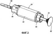
Фиг.2 изображает вид в перспективе привода для использования в электрической зубной щетке в вышеприведенном варианте осуществления настоящего изобретения;Figure 2 depicts a perspective view of a drive for use in an electric toothbrush in the above embodiment of the present invention;
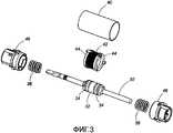
Фиг.3 изображает вид в перспективе вышеприведенного привода в разобранном виде в электрической зубной щетке в вышеприведенном варианте осуществления настоящего изобретения;Figure 3 depicts a perspective view of the above actuator disassembled in an electric toothbrush in the above embodiment of the present invention;
Фиг.4 изображает вид в перспективе участка вышеприведенного привода в электрической зубной щетке в вышеприведенном варианте осуществления настоящего изобретения; и4 is a perspective view of a portion of the above drive in an electric toothbrush in the above embodiment of the present invention; and
Фиг.5 изображает вид в разрезе электрической зубной щетки в другом варианте осуществления настоящего изобретения.5 is a sectional view of an electric toothbrush in another embodiment of the present invention.
Лучший вариант осуществления изобретенияThe best embodiment of the invention
Фиг.1 изображает электрическую зубную щетку в одном варианте осуществления настоящего изобретения. Электрическая зубная щетка имеет цилиндрическую ручку 10 для захвата рукой пользователя, привод 20, расположенный внутри ручки 10, вал 30, приводимый в движение для вибрирования приводом 20, головку 60 щетки, соединенную с возможностью отсоединения с валом 30. Привод 20 приводит в движение вал 30 для вибрирования вдоль своей оси, чтобы вызывать вибрацию щетки 62, обеспеченной на переднем конце головки 60 щетки.Figure 1 depicts an electric toothbrush in one embodiment of the present invention. The electric toothbrush has a
Ручка 10 вмещает в себя батарейку 12, действующую как электрический источник для приведения в движение привода 20. Вал 30 выполнен с возможностью на переднем конце выступа наружу через передний конец ручки 10, чтобы быть соединенным с головкой 60 щетки. На заднем концевом участке наружной периферийной поверхности ручки 10 для контакта с рукой пользователя расположен электрод 14 касания, чтобы быть соединенным с отрицательным полюсом батарейки 12. Батарейка 12 соединяется на положительном полюсе с валом 30 посредством электропроводного соединения 50. Вал 30 является электропроводным и соединяется с проводником (не изображен), который продолжается в продольном направлении внутри головки 60 щетки. Проводник выполнен на одном конце в виде электрода 64 щетки, который открывается в выемке, образованной в головке 60 щетки, прилегающей к щетке 62. С этой конфигурацией осевой участок головки 60 щетки электрически соединен с валом 30, чтобы образовать путь электрического тока, ведущий к щетке 62. Заданное электрическое напряжение прилагается между электродом 64 щетки и электродом 14 касания для прохождения микроэлектрического тока (например, 30-50 µА) между зубами пользователя и головкой щетки, таким образом, удаляя зубной налет.The
Как изображено на фиг.2-4, привод 20 оснащен корпусом 40, который закреплен на обоих концах подшипниками 46, так что вал 30 поддерживается в корпусе 40 с возможностью перемещения вдоль своей оси. Вал 30 обеспечен надежно на среднем участке постоянным магнитом 32, расположенным между парой хомутов 34. Каждая из спиральных пружин 36 расположена между хомутом 34 и подшипником 46, чтобы образовывать пружинящее вибрационное устройство вала 30. Корпус 40 обеспечен на среднем участке электромагнитным блоком для покрытия им постоянного магнита 32 и хомутов 34. Электромагнитный блок включает в себя катушку 42 и пару магнитных полюсных элементов 44, чтобы вызвать вибрацию вала при заданной частоте вдоль своей оси в результате взаимодействия между постоянным магнитом и магнитным полем, создаваемым переменным током, проходящим через катушку. Установлено, что эта частота является резонансной частотой блока электромагнита. Кроме того, переменный ток создается контрольной цепью (не изображено), управляемой батарейкой 12, как электрическим источником.As shown in FIGS. 2-4, the
Как изображено на фиг.2, вал 30 соединен на заднем конце с дискообразным электропроводным элементом 52 посредством электропроводного соединения 50. Электропроводный элемент 52 поддерживается отделяющей стенкой 16, образованной внутри ручки 10, и соединяется с положительным полюсом батарейки 12. Электропроводным соединением 50 является снопообразная спиральная пружина, которая соединяется на одном конце с задним концом вала 30 и на другом конце с электропроводным элементом 52, чтобы поглощать вибрацию вала 30 вдоль своей оси. Вал 30 выполнен с возможностью вращения вокруг своей оси при помощи подшипников 46, где вращение вокруг своей оси ограничивается спиральной пружиной 50. Спиральная пружина 50 имеет один конец, зацепленный в пазу на заднем конце вала 30, чтобы быть аксиально прикрепленной с возможностью вращения к валу 30. Спиральная пружина может быть прикреплена к валу установкой опор, сваркой или тому подобное. Вал 30 соединяется с положительным полюсом батарейки 12 посредством упругого и продолжаемого электропроводного соединения 50 в данном варианте осуществления, таким образом, поддерживая электрическое соединение между батарейкой 12 и валом 30 для стабилизации эффекта в удалении налета, даже когда вал 30 наклоняется при чистке зубов пользователя. Привод 20 собирается вместе с валом 30, электропроводным соединением 50 и электропроводным элементом 52 для обеспечения единого отформованного устройства для вставления в ручку 10. При этом ручка 10 обеспечивается стопорным кольцом 18, через которое вставляется вал 30. Стопорное кольцо 18 предназначено для ограничения вращения вала 30 вокруг своей оси.As shown in FIG. 2, the
В совокупности с или вместо осуществления осевой вибрации привод 20 может быть выполнен с возможностью вибрирования вала 30 вокруг своей оси. Фиг.5 изображает электрическую зубную щетку во втором варианте осуществления настоящего изобретения. В этом варианте осуществления водонепроницаемое уплотнение 50А применяется, вместо спиральной пружины, как электропроводное соединение 50. Другие компоненты и функции этого варианта осуществления являются такими же, как компоненты и функции первого варианта осуществления, и, таким образом, одинаковые части обозначаются такими же ссылочными позициями и обходятся без повторных пояснений. Водонепроницаемое уплотнение 50А обеспечивается для гидравлического уплотнения между отверстием 18, образованным на переднем конце ручки 10 и валом 30, выступающим наружу через отверстие 18. Водонепроницаемое уплотнение 50А образовано в форме кольца из упругого и продолжаемого электропроводного материала. Водонепроницаемое уплотнение 50А прикреплено на внутренней периферии к валу 30 и соединяется на наружной периферии с ручкой вокруг отверстия 18, чтобы поглощать вибрацию вдоль оси вала 30. Водонепроницаемое уплотнение 50А электрически соединяется на наружной периферии с электропроводом 13, который соединяется с положительным полюсом батарейки 12, так что вал 30 заряжается положительно для подачи положительного электрического потенциала на электрод щетки, соединенного с валом 30. В этом варианте осуществления вал 30 предназначен для вибрирования вдоль и вокруг своей оси, где вращение вокруг своей оси ограничивается стопорным кольцом 18, расположенным внутри ручки 10.Together with or instead of axial vibration, the
Несмотря на то, что электрод 14 касания предназначен для обеспечения отрицательного электрического потенциала относительно электрода 64 щетки в вышеизложенных вариантах осуществления, настоящее изобретение не ограничивается вышеизложенными вариантами осуществления. Электрод 14 касания может быть выполнен с возможностью наличия положительного электрического потенциала относительно электрода 64 щетки.Although the
Claims (7)
Translated fromRussianручку, заключающую в себе вал; привод, расположенный внутри упомянутой ручки и выполненный с возможностью вибрирования упомянутого вала вдоль и/или вокруг своей оси; головку щетки, соединенную с упомянутым валом; электрод касания, расположенный на наружной периферийной поверхности упомянутой ручки для контакта с рукой пользователя; электрод щетки, закрепленный в упомянутой головке щетки; и электрический источник, выполненный с возможностью создания разности потенциалов между упомянутым электродом касания и упомянутым электродом щетки, при этом упомянутый вал является электропроводным и соединяется посредством удлиняемого электропроводного соединения с электропроводным элементом, соединенным с одним из полюсов упомянутого электрического источника, и упомянутое электропроводное соединение прикрепляется на одном своем конце к упомянутому валу, и на другом конце - к упомянутому электропроводному элементу, расположенному в заданном положении внутри упомянутой ручки.1. An electric toothbrush containing
a handle enclosing a shaft; a drive located inside said handle and configured to vibrate said shaft along and / or around its axis; a brush head connected to said shaft; a touch electrode located on the outer peripheral surface of said handle for contacting a user's hand; a brush electrode fixed to said brush head; and an electric source configured to create a potential difference between said touch electrode and said brush electrode, wherein said shaft is electrically conductive and is connected by an extendable electrically conductive connection to an electrically conductive element connected to one of the poles of said electric source, and said electrically conductive connection is attached to one end to said shaft, and at the other end to said conductive element, is located Nomu in a predetermined position inside said handle.
Applications Claiming Priority (2)
| Application Number | Priority Date | Filing Date | Title |
|---|---|---|---|
| JP2006-352638 | 2006-12-27 | ||
| JP2006352638 | 2006-12-27 |
Publications (1)
| Publication Number | Publication Date |
|---|---|
| RU2405499C1true RU2405499C1 (en) | 2010-12-10 |
Family
ID=39588473
Family Applications (1)
| Application Number | Title | Priority Date | Filing Date |
|---|---|---|---|
| RU2009128666/14ARU2405499C1 (en) | 2006-12-27 | 2007-12-25 | Electric toothbrush |
Country Status (6)
| Country | Link |
|---|---|
| US (1) | US8239991B2 (en) |
| EP (1) | EP2098190A4 (en) |
| JP (1) | JP5060272B2 (en) |
| CN (1) | CN101541258B (en) |
| RU (1) | RU2405499C1 (en) |
| WO (1) | WO2008081790A1 (en) |
Cited By (1)
| Publication number | Priority date | Publication date | Assignee | Title |
|---|---|---|---|---|
| RU2815693C1 (en)* | 2022-11-08 | 2024-03-20 | Шэньчжэнь Соокас Текнолоджи Ко., Лтд. | Personal hygiene device |
Families Citing this family (19)
| Publication number | Priority date | Publication date | Assignee | Title |
|---|---|---|---|---|
| JP5176891B2 (en) | 2008-11-14 | 2013-04-03 | ミツミ電機株式会社 | Actuator and electric toothbrush using the same |
| EP2262085A1 (en)* | 2009-06-12 | 2010-12-15 | Braun GmbH | Electric appliance and electric motor drive unit for an electric appliance |
| WO2011037151A1 (en)* | 2009-09-24 | 2011-03-31 | パナソニック電工 株式会社 | Tooth cleaning device |
| EP2845566B1 (en)* | 2009-12-23 | 2019-07-03 | Koninklijke Philips N.V. | Mechanically driven resonant drive train for a power toothbrush |
| CN104901499A (en)* | 2010-06-30 | 2015-09-09 | 日本电产科宝株式会社 | Vibration actuator |
| JP5796408B2 (en)* | 2011-08-24 | 2015-10-21 | オムロンヘルスケア株式会社 | Oral care device |
| FR2995719B1 (en)* | 2012-09-20 | 2018-04-27 | Valeo Systemes De Controle Moteur | SHUTTER ACTUATOR OF A THERMAL MOTOR AIR CIRCUIT |
| JP5842789B2 (en)* | 2012-11-01 | 2016-01-13 | ミツミ電機株式会社 | Actuator and electric hairdressing beauty instrument |
| JP6139796B2 (en)* | 2014-04-16 | 2017-05-31 | コーニンクレッカ フィリップス エヌ ヴェKoninklijke Philips N.V. | Multi-function module motor mount bumper |
| US10245720B2 (en)* | 2014-09-12 | 2019-04-02 | Chris Ptak | Elastic vibrating appliance handle |
| EP3252935B1 (en)* | 2015-01-28 | 2020-01-08 | Shanghai Shift Electrics Co., Ltd. | Implement for personal cleaning and care |
| US10010167B2 (en)* | 2015-08-28 | 2018-07-03 | Enayatullah MOTAHEDY | Motorized cleaning system for a brush |
| US10244858B2 (en)* | 2017-03-07 | 2019-04-02 | BZL Medical Ltd. | Vibrating brush assembly for personal hygiene device |
| KR20200084005A (en)* | 2017-11-01 | 2020-07-09 | 코닌클리케 필립스 엔.브이. | Oral health care personal device and toothbrush head with integral light guide along the hollow drive shaft |
| CN110151349B (en)* | 2019-06-04 | 2024-08-06 | 邹和 | Electric toothbrush |
| CN110680537B (en)* | 2019-11-12 | 2025-02-18 | 倍加洁集团股份有限公司 | An electric toothbrush and its sealing and waterproof structure |
| CN110840613A (en)* | 2019-12-25 | 2020-02-28 | 希尔顿(江苏)健康科技有限公司 | An electric device for an electric toothbrush |
| US11812845B2 (en) | 2020-06-15 | 2023-11-14 | Church & Dwight Co., Inc. | Ionic toothbrush |
| CN114099033B (en)* | 2020-08-27 | 2025-06-13 | 上海携福电器有限公司 | Support structure |
Citations (2)
| Publication number | Priority date | Publication date | Assignee | Title |
|---|---|---|---|---|
| WO2005046508A1 (en)* | 2003-11-13 | 2005-05-26 | Trisa Holding Ag | Toothbrush and method for the production thereof |
| RU2371142C2 (en)* | 2006-12-22 | 2009-10-27 | Панасоник Электрик Воркс Ко., Лтд. | Electric drive and tooth brush wherein it is used |
Family Cites Families (17)
| Publication number | Priority date | Publication date | Assignee | Title |
|---|---|---|---|---|
| JP2560025B2 (en)* | 1987-04-03 | 1996-12-04 | 博 福場 | Electric electronic toothbrush |
| US4944296A (en)* | 1987-08-10 | 1990-07-31 | Hideo Suyama | Electronic toothbrush |
| EP0458868B1 (en)* | 1989-02-20 | 1995-04-26 | Solar Wide Industrial Ltd. | Dental aid |
| JPH03261407A (en)* | 1990-03-09 | 1991-11-21 | Hiroshi Fukuba | Vibration toothbrush |
| JPH0430806A (en)* | 1990-05-28 | 1992-02-03 | Hiroshi Fukuba | Electric toothbrush |
| CA2066469A1 (en) | 1991-04-22 | 1992-10-23 | Hiroshi Hukuba | Toothbrush |
| JP2604086B2 (en)* | 1992-01-16 | 1997-04-23 | 博 福場 | Toothbrush handle structure |
| JPH0690824A (en)* | 1992-03-31 | 1994-04-05 | Shiken:Kk | Motor tooth brush |
| JP3471383B2 (en)* | 1993-02-17 | 2003-12-02 | 博 福場 | electric toothbrush |
| CN1102562A (en)* | 1993-11-11 | 1995-05-17 | 史淳茂 | Electrical ion and magnetic therapy toothbrush and application method |
| CN1160586A (en)* | 1996-01-23 | 1997-10-01 | 福场博 | Ion toothbrush |
| EP0787469A1 (en)* | 1996-02-02 | 1997-08-06 | Kabushiki Kaisha Sangi | Electronic tooth device |
| GB2317555B (en)* | 1996-09-27 | 2000-12-27 | Chiaphua Ind Ltd | Toothbrushes |
| CN2273564Y (en)* | 1996-11-01 | 1998-02-04 | 毕重平 | Electric tooth brush |
| CN2271375Y (en)* | 1996-11-07 | 1997-12-31 | 中国矿业大学 | Finger-pressure ionization health toothbrush |
| JPH10243820A (en)* | 1997-03-04 | 1998-09-14 | Hiroshi Fukuba | Ion interdental brush |
| JP2008093039A (en)* | 2006-10-06 | 2008-04-24 | Matsushita Electric Works Ltd | Mouth cleaning device |
- 2007
- 2007-12-25CNCN2007800433947Apatent/CN101541258B/ennot_activeExpired - Fee Related
- 2007-12-25WOPCT/JP2007/074872patent/WO2008081790A1/enactiveApplication Filing
- 2007-12-25RURU2009128666/14Apatent/RU2405499C1/ennot_activeIP Right Cessation
- 2007-12-25USUS12/448,608patent/US8239991B2/ennot_activeExpired - Fee Related
- 2007-12-25EPEP07860101Apatent/EP2098190A4/ennot_activeWithdrawn
- 2007-12-25JPJP2007332900Apatent/JP5060272B2/ennot_activeExpired - Fee Related
Patent Citations (2)
| Publication number | Priority date | Publication date | Assignee | Title |
|---|---|---|---|---|
| WO2005046508A1 (en)* | 2003-11-13 | 2005-05-26 | Trisa Holding Ag | Toothbrush and method for the production thereof |
| RU2371142C2 (en)* | 2006-12-22 | 2009-10-27 | Панасоник Электрик Воркс Ко., Лтд. | Electric drive and tooth brush wherein it is used |
Cited By (1)
| Publication number | Priority date | Publication date | Assignee | Title |
|---|---|---|---|---|
| RU2815693C1 (en)* | 2022-11-08 | 2024-03-20 | Шэньчжэнь Соокас Текнолоджи Ко., Лтд. | Personal hygiene device |
Also Published As
| Publication number | Publication date |
|---|---|
| JP2008178678A (en) | 2008-08-07 |
| WO2008081790A1 (en) | 2008-07-10 |
| EP2098190A1 (en) | 2009-09-09 |
| CN101541258B (en) | 2011-03-30 |
| CN101541258A (en) | 2009-09-23 |
| EP2098190A4 (en) | 2011-06-15 |
| US20100115718A1 (en) | 2010-05-13 |
| US8239991B2 (en) | 2012-08-14 |
| JP5060272B2 (en) | 2012-10-31 |
Similar Documents
| Publication | Publication Date | Title |
|---|---|---|
| RU2405499C1 (en) | Electric toothbrush | |
| RU2371142C2 (en) | Electric drive and tooth brush wherein it is used | |
| RU2367377C1 (en) | Oral care apparatus | |
| JP5627236B2 (en) | Sexual stimulator | |
| US8032965B2 (en) | Electric toothbrush | |
| RU2497482C1 (en) | Electric toothbrush | |
| JP4255452B2 (en) | Ion toothbrush | |
| EP0838236A2 (en) | Magnetic stimulating apparatus for a living body | |
| JP4375482B2 (en) | Toothbrush device | |
| WO2011086960A1 (en) | Oral care device | |
| BR112018003980B1 (en) | Electronic device with a controlled direction of vibration transmission | |
| KR100537687B1 (en) | Skin care appliance | |
| US6691363B2 (en) | Power-driven toothbrush | |
| JP2009045202A (en) | Electric toothbrush and replacement brush | |
| JP2003164473A (en) | High-speed vibration toothbrush | |
| CN107617160B (en) | Beauty device | |
| US20170141638A1 (en) | Cordless oscillatory hand held apparatus | |
| US20080230073A1 (en) | Vibrating prophylactic | |
| US10455930B2 (en) | Cosmetic device | |
| CN117082973A (en) | Electric toothbrush for pet | |
| JP2004041691A (en) | Ultrasonic toothbrush | |
| CN214967009U (en) | Toothbrush head, toothbrush handle and electric toothbrush | |
| KR900007538B1 (en) | Automatic toothbrush | |
| JP2578700Y2 (en) | Battery holder with switch and portable electric interdental cleaning brush using the same | |
| JP2024010285A (en) | Vibration device |
Legal Events
| Date | Code | Title | Description |
|---|---|---|---|
| MM4A | The patent is invalid due to non-payment of fees | Effective date:20131226 |