RU2404310C1 - Linen processing machine - Google Patents
Linen processing machineDownload PDFInfo
- Publication number
- RU2404310C1 RU2404310C1RU2009116555/21ARU2009116555ARU2404310C1RU 2404310 C1RU2404310 C1RU 2404310C1RU 2009116555/21 ARU2009116555/21 ARU 2009116555/21ARU 2009116555 ARU2009116555 ARU 2009116555ARU 2404310 C1RU2404310 C1RU 2404310C1
- Authority
- RU
- Russia
- Prior art keywords
- compartment
- air
- partition
- processing
- machine according
- Prior art date
Links
- 238000012545processingMethods0.000titleclaimsabstractdescription53
- 238000005192partitionMethods0.000claimsabstractdescription75
- 238000005406washingMethods0.000claimsdescription13
- 238000001035dryingMethods0.000claimsdescription11
- 238000000034methodMethods0.000abstractdescription2
- 230000008569processEffects0.000abstractdescription2
- 239000000126substanceSubstances0.000abstract1
- 239000004753textileSubstances0.000abstract1
- 238000010438heat treatmentMethods0.000description92
- XLYOFNOQVPJJNP-UHFFFAOYSA-NwaterSubstancesOXLYOFNOQVPJJNP-UHFFFAOYSA-N0.000description14
- 238000013021overheatingMethods0.000description6
- 238000009423ventilationMethods0.000description5
- 238000013461designMethods0.000description3
- 230000005611electricityEffects0.000description3
- 239000000796flavoring agentSubstances0.000description3
- 235000013355food flavoring agentNutrition0.000description3
- 235000019645odorNutrition0.000description3
- 230000008439repair processEffects0.000description3
- 238000007664blowingMethods0.000description2
- 230000001877deodorizing effectEffects0.000description2
- 238000012986modificationMethods0.000description2
- 230000004048modificationEffects0.000description2
- 238000000926separation methodMethods0.000description2
- 238000012546transferMethods0.000description2
- 238000010276constructionMethods0.000description1
- 230000001276controlling effectEffects0.000description1
- 230000003111delayed effectEffects0.000description1
- 239000003599detergentSubstances0.000description1
- 238000010981drying operationMethods0.000description1
- 239000003779heat-resistant materialSubstances0.000description1
- 239000011810insulating materialSubstances0.000description1
- 238000010412laundry washingMethods0.000description1
- 238000012423maintenanceMethods0.000description1
- 239000000463materialSubstances0.000description1
- 230000035515penetrationEffects0.000description1
- 230000001105regulatory effectEffects0.000description1
- 238000011012sanitizationMethods0.000description1
- 230000005236sound signalEffects0.000description1
- 230000003068static effectEffects0.000description1
- 230000037303wrinklesEffects0.000description1
Images


Classifications
- D—TEXTILES; PAPER
- D06—TREATMENT OF TEXTILES OR THE LIKE; LAUNDERING; FLEXIBLE MATERIALS NOT OTHERWISE PROVIDED FOR
- D06F—LAUNDERING, DRYING, IRONING, PRESSING OR FOLDING TEXTILE ARTICLES
- D06F31/00—Washing installations comprising an assembly of several washing machines or washing units, e.g. continuous flow assemblies
- D—TEXTILES; PAPER
- D06—TREATMENT OF TEXTILES OR THE LIKE; LAUNDERING; FLEXIBLE MATERIALS NOT OTHERWISE PROVIDED FOR
- D06F—LAUNDERING, DRYING, IRONING, PRESSING OR FOLDING TEXTILE ARTICLES
- D06F29/00—Combinations of a washing machine with other separate apparatus in a common frame or the like, e.g. with rinsing apparatus
- D06F29/005—Combinations of a washing machine with other separate apparatus in a common frame or the like, e.g. with rinsing apparatus the other separate apparatus being a drying appliance
Landscapes
- Engineering & Computer Science (AREA)
- Textile Engineering (AREA)
- Accessory Of Washing/Drying Machine, Commercial Washing/Drying Machine, Other Washing/Drying Machine (AREA)
- Detail Structures Of Washing Machines And Dryers (AREA)
- Main Body Construction Of Washing Machines And Laundry Dryers (AREA)
- Elimination Of Static Electricity (AREA)
Abstract
Description
Translated fromRussianНастоящее изобретение относится к машине для обработки белья.The present invention relates to a machine for processing linen.
Обычно машины для обработки белья являются бытовыми устройствами, которые используются для чистки белья посредством стирки белья с использованием моющего средства и механического трения и сушки. Стиральные машины подразделяются на стиральные машины, сушильные машины и единые устройства, выполняющие функции как стирки, так и сушки.Typically, laundry machines are household appliances that are used to clean laundry by washing laundry using detergent and mechanical friction and drying. Washing machines are divided into washing machines, dryers and single devices that perform the functions of both washing and drying.
Настоящее изобретение относится к машине для обработки белья.The present invention relates to a machine for processing linen.
Целью настоящего изобретения является создание машины для обработки белья с повышенной эффективностью обработки белья, которая имеет улучшенный общий внешний вид.The aim of the present invention is to provide a machine for processing sheets with increased efficiency of processing sheets, which has an improved overall appearance.
Дополнительные преимущества, цели и признаки раскрытия будут изложены частично в нижеследующем описании и частично станут понятными для специалистов в данной области техники при изучении нижеследующего или практическом использовании настоящего изобретения. Цели и другие преимущества настоящего изобретения могут быть осуществлены и достигнуты при помощи конструкции, особенно указанной в его описании и формуле изобретения, а также на прилагаемых чертежах.Additional advantages, objects, and features of the disclosure will be set forth in part in the description which follows and in part will become apparent to those skilled in the art upon study of the following or practical use of the present invention. The objectives and other advantages of the present invention can be realized and achieved using the design, especially indicated in its description and claims, as well as in the accompanying drawings.
Для достижения этих целей и других преимуществ, а также в соответствии с целью настоящего изобретения, как осуществлено и широко описано в данном документе, машина для обработки белья содержит корпус и перегородку, разделяющую внутреннее отделение корпуса на первое отделение для основной стирки белья, и второе отделение для дополнительной стирки белья. Перегородкой может быть одиночная разделительная стенка.To achieve these goals and other advantages, as well as in accordance with the purpose of the present invention, as implemented and widely described herein, the laundry machine comprises a body and a partition dividing the interior of the body into a first compartment for a main laundry, and a second compartment for extra laundry. The partition may be a single partition wall.
Одиночная разделительная стенка может образовывать основание первого отделения, и верхнюю крышку второго отделения.A single dividing wall may form the base of the first compartment, and the top cover of the second compartment.
Машина для обработки белья может дополнительно содержать устройство для подачи воздуха во второе отделение.The laundry machine may further comprise a device for supplying air to the second compartment.
Устройство для подачи воздуха может отсоединяться от верхней поверхности разделительной стенки.The air supply device may be detached from the upper surface of the partition wall.
Устройство для подачи воздуха может подавать воздух из первого отделения во второе отделение.The air supply device may supply air from the first compartment to the second compartment.
На верхней поверхности разделительной стенки может быть образована выемка, и устройство для подачи воздуха может быть установлено в данной выемке.A recess may be formed on the upper surface of the partition wall, and an air supply device may be installed in the recess.
Воздухоприем может быть образован в выемке, и воздуховыпуск устройства для подачи воздуха может соединяться с воздухоприемом. Воздуховыпуск может быть, по существу, перпендикулярным воздухоприему.The air intake may be formed in the recess, and the air outlet of the air supply device may be connected to the air intake. The air outlet may be substantially perpendicular to the air intake.
Устройство для подачи воздуха может содержать кожух, закрепленный с возможностью съема на разделительной стенке, причем кожух содержит канал, вдоль которого проходит воздух, и вентилятор выдувает воздух по каналу.The device for supplying air may include a casing, mounted with the possibility of removal on the dividing wall, and the casing contains a channel along which air passes, and the fan blows air through the channel.
В другом аспекте настоящего изобретения машина для обработки белья содержит корпус, одиночную разделительную стенку, разделяющую внутреннее отделение корпуса на основное отделение и вспомогательное отделение, и устройство для подачи воздуха, установленное на одиночной разделительной стенке, причем устройство для подачи воздуха подает воздух во вспомогательное отделение.In another aspect of the present invention, the laundry treating machine comprises a housing, a single separation wall dividing the interior of the housing into a main compartment and an auxiliary compartment, and an air supply device mounted on a single separation wall, the air supply device supplying air to the auxiliary compartment.
В основном отделении может быть образовано отделение для всасывания воздуха, где воздух всасывается в устройство для подачи воздуха, и во вспомогательном отделении может быть образовано отделение для выпуска воздуха, где воздух выходит из устройства для подачи воздуха.In the main compartment, an air suction compartment may be formed, where air is sucked into the air supply device, and in the auxiliary compartment, an air discharge compartment may be formed where air exits the air supply device.
Вспомогательное отделение может быть расположено в канале для выпуска воздуха устройства для подачи воздуха.The auxiliary compartment may be located in the air outlet of the air supply device.
Необходимо понимать, что как вышеизложенное общее описание, так и нижеследующее подробное описание настоящего изобретения являются иллюстративными и поясняющими и предназначены для обеспечения дополнительного объяснения настоящего изобретения, как заявлено.It should be understood that both the foregoing general description and the following detailed description of the present invention are illustrative and explanatory and are intended to provide an additional explanation of the present invention as claimed.
Сопроводительные чертежи, которые включены для обеспечения дальнейшего понимания раскрытия и составляют часть данной заявки, иллюстрируют вариант осуществления (варианты осуществления) данного раскрытия и вместе с описанием служат для объяснения заявленного изобретения.The accompanying drawings, which are included to provide a further understanding of the disclosure and form part of this application, illustrate an embodiment (embodiments) of this disclosure and, together with the description, serve to explain the claimed invention.
На чертежах:In the drawings:
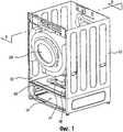
фиг.1 - перспективный вид, иллюстрирующий машину для обработки белья в соответствии с примером варианта осуществления настоящего изобретения;1 is a perspective view illustrating a laundry machine in accordance with an example embodiment of the present invention;
фиг.2 - вид в разрезе по линии II-II с фиг.1;figure 2 is a view in section along the line II-II of figure 1;
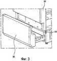
фиг.3 - перспективный вид, иллюстрирующий переднюю часть съемного выдвижного ящика, расположенного в корпусе на фиг.1;figure 3 is a perspective view illustrating the front of a removable drawer located in the housing of figure 1;
фиг.4 - перспективный вид, иллюстрирующий устройство для подачи воздуха на фиг.1;4 is a perspective view illustrating a device for supplying air in figure 1;
фиг.5 - перспективный вид, иллюстрирующий состояние верхнего кожуха на фиг.4, отделенного от нижнего кожуха;5 is a perspective view illustrating the state of the upper casing in figure 4, separated from the lower casing;
фиг.6 - вид, схематически иллюстрирующий поток воздуха внутри выдвижного ящика;6 is a view schematically illustrating air flow inside a drawer;
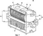
фиг.7 - перспективный вид, иллюстрирующий нагревательное устройство на фиг.5;Fig.7 is a perspective view illustrating the heating device of Fig.5;
фиг.8 - перспективный вид, иллюстрирующий машину для обработки белья в соответствии с другим примером варианта осуществления настоящего изобретения.8 is a perspective view illustrating a laundry machine in accordance with another example embodiment of the present invention.
Подробно будет сделана ссылка на конкретные варианты осуществления настоящего изобретения, примеры которых проиллюстрированы на сопроводительных чертежах. Там, где возможно, подобные ссылочные позиции будут использоваться на чертежах для обозначения одинаковых или подобных элементов.Reference will be made in detail to specific embodiments of the present invention, examples of which are illustrated in the accompanying drawings. Where possible, similar reference numerals will be used throughout the drawings to refer to the same or like elements.
Как показано на фиг.1 и 2, машина для обработки белья содержит корпус 10 и перегородку 16. Перегородка 16 разделяет внутреннее отделение на, по меньшей мере, два отделения. Перегородка 16 может быть одиночной перегородкой, которая будет описана подробно ниже. Одиночная перегородка 16 может разделять внутреннее отделение корпуса 10 на первое отделение или основное отделение 12 и второе отделение или вспомогательное отделение 14. Основная обработка белья может выполняться в первом отделении или основном отделении 12. Первое отделение 12 для обработки белья может содержать устройство для стирки белья или устройство для сушки белья. Дополнительная обработка белья может выполняться во втором отделении или дополнительном отделении 14. Переключатель 13 расположен на корпусе 10, который позволяет пользователю выбирать желаемые операции для белья.As shown in figures 1 and 2, the machine for processing linen includes a
В данном документе указанная основная обработка белья может означать известные операции стирки и/или сушки, и дополнительная обработка белья может означать дополнительные операции стирки, сушки или освежения белья или может означать операции сушки или освежения белья небольшого размера. Термин «освежение» может означать процесс удаления морщинок, уничтожения запаха, санитарную обработку, снятия статического электричества или нагревания белья посредством подачи воздуха, нагретого воздуха, пара, воды на белье. Термин «белье» может означать не только постельное белье, но также все виды предметов одежды, таких как обувь, носки, перчатки и головные уборы. Таким образом, белье означает все виды белья, для которых могут выполняться операции обработки белья.Herein, said main laundry treatment may mean known washing and / or drying operations, and additional laundry processing may mean additional washing, drying or refreshing operations of the laundry, or may mean drying or refreshing operations of small items. The term “refreshment” may mean the process of removing wrinkles, eliminating odors, sanitizing, removing static electricity or heating the laundry by supplying air, heated air, steam, water to the laundry. The term “underwear” can mean not only bedding, but also all kinds of items of clothing, such as shoes, socks, gloves and hats. Thus, laundry means all types of laundry for which laundry processing operations can be performed.
Корпус 10 определяет внешний вид машины для обработки белья. В корпусе 10 могут быть установлены различные элементы. Вращающийся барабан 20 может быть установлен в первом отделении 12 в корпусе 10, и съемный выдвижной ящик 30 может быть установлен во втором отделении 14. Барабан 20 и выдвижной ящик 30 выполнены с возможностью вмещения белья. Если машина для обработки белья выполнена в качестве стиральной машины или одиночного устройства, имеющего функции как стирки, так и сушки, дополнительно может быть установлен бак (не показан) для вмещения воды для стирки, и барабан 20 может быть установлен в баке.The
Корпус 10 может быть образован из двух отдельных элементов, которые включают в себя первое отделение 12 и второе отделение 14. Более конкретно, корпус 10 может содержать пару первых боковых стенок на противоположных сторонах первого отделения 12 для обработки белья и пару вторых боковых стенок на противоположных сторонах второго отделения 14 для обработки белья, причем пара первых боковых стенок примыкает к паре вторых боковых стенок. В качестве альтернативы корпус 10 может быть образован из одного элемента. В одном варианте осуществления первое отделение 12 и второе отделение 14 образованы в корпусе 10, выполненном из одного элемента. Более конкретно, корпус 10 может включать в себя первую боковую стенку и вторую боковую стенку, причем каждая из первой и второй боковых стенок проходит непрерывно и не прерывается от первого отделения 12 для обработки белья до второго отделения 14 для обработки белья, как показано, например, на фиг.8. Если первое отделение 12 и второе отделение 14 образованы в корпусе 10, выполненном из одного элемента, сборка корпуса 10 будет простой, и, соответственно, время, необходимое для сборки, будет уменьшено.The
В соответствии со стиральной машиной данного варианта осуществления корпус 10, выполненный из одного элемента, включает в себя первое отделение 12 и второе отделение 14, и он дополнительно включает в себя перегородку 16, которая разделяет внутреннее отделение корпуса 10 на первое отделение 12 и второе отделение 14. Перегородка 16 может быть реализована в виде стенки, расположенной внутри корпуса 10, которая проходит между первой боковой стенкой и второй боковой стенкой. Перегородка 16 делит внутреннее отделение по горизонтали на верхнее отделение, соответствующее первому отделению 12, и нижнее отделение, соответствующее второму отделению 14. Однако настоящее изобретение не ограничивается указанным.According to the washing machine of this embodiment, the
То есть в соответствии с данным вариантом осуществления корпус 10 включает в себя перегородку 16, которая одновременно используется в качестве основания первого отделения 12 и в качестве верхней крышки второго отделения 14. Более конкретно, перегородка 16 имеет первую сторону и вторую сторону, причем первая сторона открыта в первое отделение 12 для обработки белья, и вторая сторона открыта во второе отделение 14 для обработки белья.That is, in accordance with this embodiment, the
Так как одиночная перегородка 16 используется в качестве основания первого отделения 12 и в качестве верхней крышки второго отделения 14, сборка будет очень простой, и, соответственно, время, необходимое для сборки, будет уменьшено по сравнению со случаем, включающим в себя отдельное основание первого отделения 12 и отдельную верхнюю крышку второго отделения 14. Наличие одиночной перегородки 16 по сравнению с отдельной перегородкой для каждого из первого и второго отделений 12, 14 обеспечивает простую конструкцию машины для обработки белья в целом и обеспечивает приятный внешний вид машины для обработки белья. Кроме того, использование одиночной перегородки 16 упрощает сборку и уменьшает затраты вследствие уменьшения необходимого материала по сравнению с использованием отдельных перегородок. В конечном счете одиночная перегородка 16 обеспечивает эффективное использование первого и второго отделений 12, 14 и легкий доступ в первое отделение 12.Since a
Кроме того, машина для обработки белья может дополнительно включать в себя устройство 40 для подачи воздуха для подачи воздуха или нагретого воздуха во второе отделение 14.In addition, the laundry machine may further include an
Устройство 40 для подачи воздуха может быть расположено в первом отделении 12, и предусматривается, что устройство для подачи воздуха располагается на верхней поверхности перегородки 16. Перегородка 16 включает в себя отверстие 15, так что воздух подается через перегородку 16 и во второе отделение 14 для обработки белья. Устройство 40 для подачи воздуха включает в себя воздуховыпуск, который может непосредственно соединяться с отверстием 15 в перегородке 16. Отверстие 15 расположено в центральной части перегородки.An
Барабан 20, предназначенный для вращения, может быть установлен в первом отделении 12, и выдвижной ящик 10 может быть установлен во втором отделении 14. Объем первого отделения 12 может, по существу, быть больше объема второго отделения 14. В результате для эффективного использования внутреннего отделения предусматривается, что устройство 40 для подачи воздуха располагается в первом отделении 12, а не во втором отделении 14. Такое расположение позволяет максимизировать величину внутреннего объема второго отделения 14, пригодного для вмещения белья. Кроме того, расположение устройства 40 для подачи воздуха на наружной стороне второго отделения 14 упрощает конструкцию второго отделения 14 и обеспечивает больше свободы исполнения второго отделения 14. В конечном счете, так как внутренняя часть второго отделения 14 является легко доступной для пользователя через выдвижной ящик 30, размещение устройства 40 для подачи воздуха на площади, отличной от второго отделения 14, обеспечивает дополнительную степень безопасности для пользователя.A
Расположение устройства 40 для подачи воздуха в первом отделении 12 для обработки белья с подачей воздуха через отверстие 15 в перегородке 16 обеспечивает в основном направленный вниз воздушный поток во второе отделение 14 для обработки белья. Этот направленный вниз воздушный поток особенно полезен для сушки или обработки ботинок 100, так как воздух подается вниз на верх ботинка 100 для охватывания верха ботинка 100 воздушным потоком по сравнению с горизонтальным воздушным потоком, который может только направляться на одну сторону ботинка, или направленным вверх воздушным потоком, который будет задерживаться подошвой ботинка.The arrangement of the
Кроме того, направленный вниз воздушный поток перемещается в нижнюю часть выдвижного ящика и затем будет стремиться распространяться во всех направлениях, обеспечивая полностью распределенный воздушный поток и уменьшая возможные мертвые зоны с небольшим воздушным потоком или без него в выдвижном ящике 30.In addition, the downward-directed airflow moves to the bottom of the drawer and will then tend to spread in all directions, providing a fully distributed airflow and reducing possible dead zones with little or no airflow in the
Более конкретно, выдвижной ящик 30 включает в себя нижнюю стенку и множество боковых стенок, которые образуют закрытое отделение с открытой верхней стороной. Высота боковых стенок может быть меньше ширины и глубины выдвижного ящика 30, так что выпускное отверстие воздушного потока из устройства 40 для подачи воздуха расположено относительно близко к нижней части выдвижного ящика, так что нижняя часть выдвижного ящика стремится переориентировать направленный вниз воздушный поток на наружную сторону во всех направлениях. Нижняя часть выдвижного ящика и множество боковых стенок могут быть выполнены с возможностью предотвращения прохождения воздуха через них, чтобы максимизировать количество воздуха, который переориентируется вверх. Однако предусматривается, чтобы нижняя часть выдвижного ящика и/или боковые стенки выдвижного ящика могли содержать одно или более отверстий, таких как ряд небольших вентиляционных отверстий, сетка или сетчатый фильтр, для обеспечения прохождения некоторой части воздушного потока через них.More specifically, the
Устройство 40 для подачи воздуха может быть расположено с возможностью съема на перегородке 16, более конкретно на верхней стороне перегородки 16. Здесь выемка 17 может быть образована на перегородке 16 для вмещения устройства 40 для подачи воздуха. Более конкретно, центральная часть перегородки 16 содержит утопленную часть (или выемку) 17, проходящую вниз на верхней стороне перегородки 16, и, по существу, нижняя сторона перегородки содержит проходящую вверх часть, окружающую центральную часть, подробное описание которой будет приведено ниже в пояснении, касающемся рециркуляции воздушного потока.The
Барабан 20 расположен в первом отделении 12 над перегородкой 16, и, следовательно, возможно, что вода может попадать на перегородку 16 вследствие вращения барабана во время стирки, полоскания или сушки при высокой скорости. В результате выемка 17 может также собирать воду, попадающую на перегородку 16. В дополнение к этому выемка 17 вмещает устройство 40 для подачи воздуха. В результате, хотя не показано на чертежах, устройство для слива воды может быть установлено в заданной части выемки 17 для слива собранной воды, не контактируя с устройством 40 для подачи воздуха. В качестве альтернативы нижняя поверхность выемки может иметь наклон, достаточный для того, чтобы собранная вода не проходила по направлению к устройству 40 для подачи воздуха.The
Как показано на фиг.2, устройство 40 для подачи воздуха может быть расположено на перегородке 16, и оно может подавать нагретый воздух во второе отделение 14. Конкретно, устройство 40 для подачи воздуха нагревает воздух внутри первого отделения 12 корпуса 10 и подает нагретый воздух во второе отделение 14. Здесь воздух из первого отделения 12 будет проходить вниз по направлению ко второму отделению 14 после нагревания устройством 40 для подачи воздуха. Направленный вниз воздушный поток направляется к нижней части второго отделения 14 и затем будут стремиться распространяться во всех направлениях, обеспечивая полностью распределенный воздушный поток и уменьшая возможные мертвые зоны с незначительным воздушным потоком или без него во втором отделении 14.As shown in FIG. 2, the
Таким образом, первое отделение 12 образует заданное отделение, в котором воздух всасывается в устройство 40 для подачи воздуха, то есть отделение для всасывания воздуха, и второе отделение 14 образует заданное отделение, в котором воздух выходит из устройства 40 для подачи воздуха, то есть отделение для выпуска воздуха. С точки зрения устройства 40 для подачи воздуха, первое отделение 12 расположено в канале для всасывания воздуха, и второе отделение 14 расположено в канале для выпуска воздуха. В результате вспомогательный впускной или выпускной канал для устройства 40 для подачи воздуха не нужно образовывать. Устройство 40 для подачи воздуха выполнено с возможностью подачи воздуха во второе отделение 14 для обработки белья без прохождения через барабан 20.Thus, the
Фиг.3 изображает перспективный вид, иллюстрирующий вид спереди съемного выдвижного ящика 30, расположенного во втором отделении 14 корпуса 10.Figure 3 depicts a perspective view illustrating a front view of a
Как показано на фиг.3, выдвижной ящик 30 имеет закрытое отделение с открытой верхней стороной. Более конкретно, выдвижной ящик 30 содержит нижнюю стенку и множество боковых стенок, которые образуют закрытое отделение, имеющее открытую верхнюю сторону. Выдвижной ящик 30, по существу, занимает все второе отделение 14 для обработки белья. Приемное отделение образовано в выдвижном ящике 30, и приемное отделение вмещает белье. После стирки или сушки белья в первом отделении 12 пользователь загружает выстиранное или высушенное белье в выдвижной ящик 30, расположенный во втором отделении 14, для выполнения дополнительной обработки или освежения. Нижняя сторона выдвижного ящика и/или боковые стенки выдвижного ящика могут содержать множество отверстий, таких как множество маленьких вентиляционных отверстий, сетка или сетчатый фильтр, для прохождения через них воздуха.As shown in FIG. 3, the
Нежелательные запахи белья, используемого один или два раза, могут быть удалены с помощью дезодорирующего фильтра (не показан) или устройства для добавления ароматизирующих веществ (не показано), которые могут быть дополнительно установлены в выдвижном ящике 30 в соответствии с данным вариантом осуществления. Дезодорирующий фильтр удаляет запахи из белья, и устройство для добавления ароматизирующих веществ добавляет ароматизирующие вещества в белье, так что пользователю может быть приятно во время носки белья. Фильтр или устройство для добавления ароматизирующих веществ могут быть расположены во втором отделении 14, конкретно в передней части внутри выдвижного ящика 30.Unwanted odors of laundry used once or twice can be removed using a deodorizing filter (not shown) or a flavoring device (not shown), which can be additionally installed in
Во время работы устройства 40 для подачи воздуха может случиться так, что пользователь по ошибке может открыть выдвижной ящик 30. Следовательно, машина для обработки белья в соответствии с данным вариантом осуществления может дополнительно содержать сенсорное устройство 50 для определения положения выдвижного ящика 30.During operation of the
Сенсорное устройство 50 может контролировать положение выдвижного ящика 30, и предусматривается, что сенсорное устройство 50 определяет, выдвигается ли выдвижной ящик 30 в открытое положение. Например, сенсорное устройство 50 может быть выполнено в качестве конечного переключателя, определяющего, выдвигается ли выдвижной ящик 30 наружу.The
Если выдвижной ящик 30 перемещается в открытое положение наружу, сенсорное устройство 50 генерирует сигнал открытия, и сигнал открытия передается в устройство управления (не показано) машины для обработки белья. Устройство управления управляет устройством 40 для подачи воздуха в соответствии с сигналом открытия сенсорного устройства 50. При приеме сигнала открытия с сенсорного устройства 50 устройство управления отключает устройство 40 для подачи воздуха для предотвращения прохождения нагретого воздуха по направлению к пользователю. Если сенсорное устройство 50 выполнено в виде концевого выключателя, концевой выключатель непосредственно отключает устройство 40 для подачи воздуха, когда выдвижной ящик 30 выдвигается в открытое положение.If the
Как показано на фиг.5, устройство 40 для подачи воздуха в соответствии с данным вариантом осуществления содержит вентилятор 51 для выдувания воздуха из устройства 40 для подачи воздуха и нагревательное устройство 60 для нагревания воздуха. Устройство управления установлено для управления устройством 40 для подачи воздуха. Устройство управления сначала отключает нагревательное устройство 60, и затем отключается вентилятор 51 через заданный период времени после отключения нагревательного устройства 60. Если нагревательное устройство 60 работает, температура внутри корпуса 10 повышается. Когда вентилятор 51 отключается через заданный период времени после отключения нагревательного устройства 60, например одну или две минуты, воздух внутри корпуса 10 будет циркулировать в течение еще одной или двух минут, и, соответственно, температура внутри корпуса 10 будет понижаться.As shown in FIG. 5, the
Хотя на чертежах не показано, машина для обработки белья в соответствии с данным вариантом осуществления может содержать устройство сигнализации, выполненное с возможностью предупреждения пользователя визуально или с помощью звуковых сигналов о том, выдвигается ли выдвижной ящик 30 в открытое положение. Когда сенсорное устройство 50 генерирует и передает сигнал об открытии в устройство управления, устройство управления отключает устройство 40 для подачи воздуха, и оно управляет устройством сигнализации для информирования пользователя об открытом состоянии выдвижного ящика 30. Затем пользователь видит, что выдвижной ящик 30 открыт, и выполняет корректировку, например закрывает выдвижной ящик 30 и повторно приводит в действие устройство 40 для подачи воздуха.Although not shown in the drawings, the laundry machine in accordance with this embodiment may include an alarm device configured to alert the user visually or by means of sound signals that the
Если работа машины для обработки белья прерывается из-за открытого состояния выдвижного ящика 30, машина для обработки белья может отображать оставшееся количество рабочего времени для выбранного режима, так что пользователь может знать, сколько осталось времени для выбранного режима, и пользователь может решать, повторно привести в действие машину для обработки белья или выгрузить белье.If the operation of the laundry machine is interrupted due to the open state of the
Устройство 40 для подачи воздуха, которое подает нагретый или ненагретый воздух в выдвижной ящик 30, будет описано подробно ниже.An
Как показано на фиг.4 и 5, устройство 40 для подачи воздуха в соответствии с данным вариантом осуществления содержит кожух 42. Кожух 42 соединяется с возможностью съема с верхней поверхностью перегородки 16, и он содержит канал для воздушного потока.As shown in FIGS. 4 and 5, the
Кожух содержит канал для воздушного потока, через который проходит воздух, и в кожухе 42 могут быть установлены вентилятор 51, нагревательное устройство 60 и вспомогательное устройство управления, которые будут описаны ниже.The casing comprises a channel for air flow through which air passes, and a
В данном документе кожух 42 выполнен как одно целое и содержит верхний кожух 44 и нижний кожух 46. Нижний кожух 46 соединяется с возможностью съема с верхней поверхностью перегородки 16 с помощью, например, одного или более выступов 94, вставляемых в соответствующие пазы в перегородке 16, и одного или более круглых выступов 92, через которые проходит крепежный элемент и прикрепляется к перегородке 16. Верхний кожух 44 соединяется с возможностью съема с нижним кожухом 46 с помощью множества крючков 45, расположенных на верхнем кожухе 44, и множества элементов 47 для зацепления, расположенных на нижнем кожухе 46. Съемные верхний и нижний кожухи 44 и 46 упрощают и облегчают ремонт внутренних элементов устройства 40 для подачи воздуха во время технического обслуживания и ремонта.In this document, the
Множество ребер 90 может быть образовано на нижнем кожухе 46 для упрочнения нижнего кожуха 46. Ребра 90 могут располагаться вдоль обеих сторон нижнего кожуха 46. Кожух 42 также может содержать элементы 82 и 84 для фиксации провода для закрепления проводов, соединяющих внутренние элементы устройства 40 для подачи воздуха с наружной стороной.A plurality of ribs 90 can be formed on the
Устройство 40 для подачи воздуха может быть расположено на верхней поверхности перегородки 16, то есть под барабаном 20 (см. фиг.1), как упомянуто выше. При вращении барабана 20 вода может попадать на устройство 40 для подачи воздуха. Если вода проникнет в кожух 42, внутренние элементы кожуха 42, такие как нагревательное устройство 60, могут выйти из строя или повредиться. Особенно если верхний кожух 44 и нижний кожух 46 кожуха 42 выполнены соответственно из отдельных элементов, вода может проходить через участок соединения между ними. На основании этого устройство 40 для подачи воздуха в соответствии с данным вариантом осуществления может содержать устройство для предотвращения проникновения воды для предотвращения проникновения воды через участок соединения между верхним кожухом 44 и нижним кожухом 46.The
Конкретно, устройство для предотвращения проникновения воды включает в себя первую выступающую часть 41, которая проходит вниз от кромки верхнего кожуха 44, и вторую выступающую часть 48, которая проходит вверх от кромки нижнего кожуха 46.Specifically, the device for preventing water penetration includes a first protruding
Здесь первая выступающая часть 41 образована вдоль кромки верхнего кожуха 44, охватывая заданную часть кромки нижнего кожуха 46 и, таким образом, закрывая кромку нижнего кожуха 46. Вторая выступающая часть 48 соединяется с первой выступающей частью 41, конкретно с внутренней стороной первой выступающей части 41. В результате вода на верхней части кожуха 42 последовательно проходит вдоль поверхности первой выступающей части 41, не проходя в кожух 42 вдоль участка соединения, и она проходит по направлению к перегородке 16.Here, the first protruding
Как упомянуто выше, канал для воздушного потока расположен в кожухе. Канал образован между нижним кожухом 46 и верхним кожухом 44, и воздух проходит вдоль канала, изображенного в виде стрелки на фиг.5. Вентилятор 51 для выдувания воздуха вдоль канала и нагревательное устройство 60 для нагревания воздуха могут быть расположены внутри кожуха. Хотя на фиг.5 показано, что вентилятор 51 и нагревательное устройство 60 расположены последовательно вдоль направления прохождения воздуха, так что вентилятор 51 выдувает воздух в нагревательное устройство 60, настоящее изобретение не ограничивается этим, и также можно расположить нагревательное устройство 60 и вентилятор 51 последовательно таким образом, чтобы вентилятор 51 всасывал воздух из нагревательного устройства 60. Вентилятором 51 является центробежный вентилятор в изображенном варианте осуществления. Однако предусматривается, что могут использоваться альтернативные конструкции вентиляторов, такие как осевой вентилятор или сирокко.As mentioned above, the channel for air flow is located in the casing. A channel is formed between the
При приведении в действие вентилятора 51 воздух с наружной стороны кожуха 42 всасывается в кожух 42 через впускное отверстие 43. В данном документе предусматривается, что обороты в минуту вентилятора 51 регулируются. Так как скорость вращения вентилятора 51 регулируется, количество воздуха, подаваемого вентилятором 51, может регулироваться. Воздух, всасываемый в кожух 42, нагревается нагревательным устройством 60, и нагретый воздух проходит через выпускное отверстие 49. В этом случае выпускное отверстие 49 соединено с отверстием 15 (см. фиг.2), образующим отверстие для впуска нагретого воздуха в перегородке 16, и направлено вниз. Предусматривается, что выпускное отверстие 49 приблизительно перпендикулярно отверстию 15 для впуска нагретого воздуха и непосредственно соединяется с отверстием 15 для впуска нагретого воздуха. В результате нагретый воздух может проходить вниз по направлению ко второму отделению 14, то есть выдвижному ящику 30.When the
Фиг.6 изображает вид, схематически иллюстрирующий поток воздуха, подаваемого в выдвижной ящик 30 устройством 40 для подачи воздуха.6 is a view schematically illustrating the flow of air supplied to the
Как показано на фиг.6, воздух, выходящий через выпускное отверстие 49, проходит в отверстие 15 для впуска нагретого воздуха, и воздух проходит по направлению к боковой верхней части внутри выдвижного ящика 30 через центральную нижнюю часть. Поэтому мертвая зона внутри выдвижного ящика 30, в которую воздух не проходит, может быть максимально уменьшена. Кроме того, как показано на фиг.2, нижняя сторона перегородки 16 может содержать выступающую вверх часть, окружающую утопленную часть на верхней стороне перегородки 16. Эта выступающая вверх часть может включать в себя наклонные части 162, выполненные с возможностью переориентации воздушного потока внутрь по направлению к центральной части перегородки 16, а также вниз от перегородки 16 и назад по направлению к выдвижному ящику 30. Это устройство обеспечивает рециркуляцию некоторой части воздуха, что может способствовать нагреванию, сушке или другой обработке белья в выдвижном ящике 30.As shown in FIG. 6, the air exiting through the
Как показано на фиг.6, зазор 32 образован между перегородкой 16 и выдвижным ящиком 30 для обеспечения прохождения воздуха через него и выхода из выдвижного ящика 30 для последующего выхода из второго отделения 14 для обработки белья. Кроме того, если белье загружено на нижнюю поверхность выдвижного ящика 30, воздух может максимально контактировать с бельем. Нижняя часть выдвижного ящика 30 стремится переориентировать направленный вниз воздушный поток на наружную сторону во всех направлениях к боковым стенкам выдвижного ящика. Соответственно боковые стенки выдвижного ящика стремятся переориентировать воздушный поток вверх по направлению к перегородке 16. В конечном счете перегородка 16 стремится переориентировать воздушный поток внутрь по направлению к центральной части перегородки 16, где воздушный поток соединяется с направленным вниз воздушным потоком и рециркулирует.As shown in Fig.6, the
Как показано на фиг.4 и 5, устройство 40 для подачи воздуха в соответствии с данным вариантом осуществления может дополнительно содержать первый датчик 70 температуры, который измеряет температуру нагретого воздуха. Нагревательным устройством 60 можно управлять в соответствии со значениями температуры, измеренными первым датчиком 70, для подачи нагретого воздуха.As shown in FIGS. 4 and 5, the
Первый датчик 70 может быть установлен в заданной части внутри канала, и подразумевается, что первый датчик 70 температуры установлен в конце канала, то есть рядом с выпускным отверстием 49. Вспомогательное устройство управления, расположенное в устройстве 40 для подачи воздуха, управляет работой нагревательного устройства 60 в соответствии со значениями температуры, измеренными первым датчиком 70 температуры, и затем оно регулирует температуру нагретого воздуха, поданного во второе отделение 14.The
При управлении нагревательным устройством 60 посредством измерения температуры нагретого воздуха, нагреваемого нагревательным устройством 60, могут быть установлены одно устройство управления или два или более устройств управления.When controlling the
Если установлено, по меньшей мере, два устройства управления, например основное устройство управления и вспомогательное устройство управления, основное устройство управления управляет всей работой барабана 20 и устройства 40 для подачи воздуха. Температуры, измеренные первым датчиком 70 температуры, могут передаваться в основное устройство управления.If at least two control devices are installed, for example, a main control device and an auxiliary control device, the main control device controls the entire operation of the
Основное устройство управления управляет работой нагревательного устройства 60 и вентилятора 51, образующих устройство 40 для подачи воздуха, в соответствии с температурами, измеренными первым датчиком 70 температуры. В этом случае сигнал команды, генерируемый основным устройством управления, передается во вспомогательное устройство управления, расположенное в устройстве 40 для подачи воздуха. Следовательно, вспомогательное устройство управления управляет работой нагревательного устройства 60 и вентилятора 51 в соответствии с сигналом команды основного устройства управления. При приеме сигнала команды из основного устройства управления вспомогательное устройство управления может выполнять только двухпозиционное управление нагревательным устройством 60 или вентилятором 51 для упрощения данной конфигурации.The main control device controls the operation of the
Нагревательное устройство 60, расположенное вдоль воздушного канала, нагревает воздух для получения нагретого воздуха. Подразумевается, что нагревательное устройство 60 выполнено с возможностью только нагрева воздуха и минимизации передачи тепла на кожух 42.A
Фиг.7 изображает перспективный вид, иллюстрирующий только нагревательное устройство 60 на фиг.5.FIG. 7 is a perspective view illustrating only the
Как показано на фиг.7, нагревательное устройство 60, расположенное в устройстве 40 для подачи воздуха, в соответствии с данным вариантом осуществления может содержать нагревательный элемент 61 для нагревания выдуваемого воздуха и корпус 62 для вмещения нагревательного элемента 61. Корпус 62 содержит канал, через который проходит воздух, и он поддерживает нагревательный элемент 61 и предотвращает передачу тепла, генерируемого нагревательным элементом 61, на кожух 42 (см. фиг.5).As shown in FIG. 7, a
Различные нагревательные элементы могут быть использованы в устройстве для подачи воздуха, включая нагревательный элемент с положительным температурным коэффициентом. Нагревательный элемент с положительным температурным коэффициентом является подходящим, так как им легко управлять.Various heating elements can be used in an air supply device, including a positive temperature coefficient heating element. A positive temperature coefficient heating element is suitable since it is easy to control.
Может быть установлен один нагревательный элемент. Однако подразумевается, что нагревательный элемент может быть разделен по горизонтали на первый нагревательный элемент 61a и второй нагревательный элемент 61b вдоль канала. Первый и второй нагревательные элементы 61a и 61b размещаются соответственно в верхний корпус 64 и нижний корпус 66. Разделительная стенка 65 может быть установлена между первым и вторым нагревательными элементами 61a и 61b для предотвращения перегрева нагревательных элементов 61a и 61b.One heating element can be installed. However, it is understood that the heating element may be horizontally divided into a
Любой из двух или оба нагревательных элемента 61a и 61b могут приводиться в действие селективно или одновременно, так что воздух может соответственно нагреваться в соответствии с количеством воздуха с целью экономии энергии. Конкретно, если количество воздуха является относительно небольшим, любой из первого и второго нагревательных элементов 61a и 61b приводится в действие для нагревания воздуха. Если количество воздуха является относительно большим, оба первый и второй нагревательные элементы 61a и 61b приводятся в действие одновременно для нагревания воздуха.Any of the two or both of the
Корпус 62 предотвращает прямой контакт нагревательного элемента 61 с внутренней частью кожуха 42, а также поддерживает нагревательный элемент 61 и содержит воздушный канал. Как показано на фиг.7, корпус 62 может поддерживать нагревательный элемент 61 некоторым образом, чтобы он не создавал помех для потока воздуха вдоль нагревательного элемента 61. Поэтому корпус может быть выполнен из жаропрочного материала, имеющего низкую удельную теплопроводность, или теплоизоляционного материала.The
Корпус 62 может быть выполнен как одно целое из одного элемента, и подразумевается, что корпус 62 может быть выполнен из отдельных элементов, которые будут собраны. Конкретно, корпус 62, изображенный на фиг.7, включает в себя верхний корпус 64 и нижний корпус 66, которые соединяются друг с другом. Наличие корпуса 62, выполненного из отдельных элементов, позволяет легко выполнять разборку и повторную сборку для ремонтных работ.The
Так как нагревательный элемент 61 в соответствии с данным вариантом осуществления близко расположен от кожуха 42 устройства 40 для подачи воздуха, корпус 62 может предотвращать передачу тепла нагревательного элемента 61 на кожух 42 в вертикальном направлении, не только предотвращая контакт нагревательного элемента 61 с внутренней частью кожуха 42. То есть хотя тепло нагревательного элемента 61 может передаваться в воздух, проходящий вдоль канала, тепло не будет передаваться по направлению к кожуху 42, расположенному напротив воздушного канала.Since the
Конкретно, как показано на фиг.7, верхний корпус 64 закрывает верхний нагревательный элемент 61a, а нижний корпус 66 закрывает нижний нагревательный элемент 61b. Воздух проходит в корпус 62 через открытые части верхнего корпуса 64 и нижнего корпуса 66, например, слева направо. Таким образом, нагревательный элемент 61 может косвенно контактировать с кожухом 42 через корпус 62, и может быть предотвращено прохождение тепла, генерируемого нагревательным элементом 61, к стенкам кожуха 42 благодаря верхнему и нижнему корпусам 64 и 66. Дополнительные признаки безопасности включены в нагревательное устройство 60. Например, нагревательное устройство 60 содержит клеммы для подачи электричества в нагревательный элемент 61. Как показано на фиг.7, клеммы расположены на расстоянии друг от друга как в горизонтальном направлении, так и вертикальном направлении.Specifically, as shown in FIG. 7, the
Если нагревательное устройство 60 приводится в действие без достаточного количества подаваемого воздуха, температура нагревательного элемента 61 может значительно повыситься, и возможно, что нагревательный элемент 61 может повредиться. Поэтому в данном варианте осуществления может быть использовано средство для предотвращения перегрева.If the
Конкретно, нагревательное устройство 60 в соответствии с данным вариантом осуществления может дополнительно содержать второй датчик 68 температуры, который измеряет температуру нагревательного элемента 61. В дополнение к первому датчику 70 температуры (см. фиг.5) для измерения температуры нагретого воздуха второй датчик 68 температуры измеряет температуру нагревательного элемента 61. Второй датчик 68 температуры расположен рядом с нагревательным элементом 61 для измерения температуры нагревательного элемента 61. Измеренные значения температуры могут передаваться в устройство управления, включающее в себя основное устройство управления и вспомогательное устройство управления. Если переданная температура выше заданного значения, устройство управления, конкретно основное устройство управления, определяет, что нагревательный элемент 61 перегрет, и отключает нагревательный элемент 61. Если установлено вспомогательное устройство управления, оно принимает соответствующую команду из основного устройства управления и отключает нагревательный элемент 61.Specifically, the
В дополнение ко второму датчику 68 температуры может быть установлен плавкий предохранитель 72 в качестве средства для предотвращения перегрева с целью отключения нагревательного элемента 61. Как показано на фиг.7, плавкий предохранитель 72 может быть расположен в корпусе 62.In addition to the
Конкретно, открытая часть 67 образована в верхнем корпусе 64, и плавкий предохранитель 72 располагается в открытой части 67. Тепло нагревательного элемента 61 передается в плавкий предохранитель 72 через открытую часть 67, так что температура может регистрироваться более эффективно.Specifically, the
Если образована такая открытая часть 67, тепло нагревательного элемента 61 выходит из корпуса 62 через открытую часть 67 и проходит непосредственно на кожух 42. В результате нагревательный элемент 61 в соответствии с данным вариантом осуществления содержит закрывающий элемент 69 для закрытия открытой части 67 с целью предотвращения непосредственного прохождения тепла нагревательного элемента 61 на кожух 42. Закрывающий элемент 69 может быть выполнен в виде отдельного элемента, и предусматривается, как показано на фиг.7, что закрывающий элемент 69 может быть выполнен как одно целое с верхним корпусом 64. В данном документе закрывающий элемент 69 выполнен с возможностью закрытия верхней части 67 и содержит изогнутую часть, так что тепло не может проходить по направлению к кожуху 42 через открытую часть 67.If such an
Плавкий предохранитель 72 соединяется с нагревательным элементом 61. Если температура нагревательного элемента 61 становится выше заданной температуры, плавкий предохранитель 72 будет отключать электричество, подаваемое в нагревательный элемент 61, для предотвращения перегрева нагревательного элемента 61. Как показано на фиг.7, закрывающий элемент 69 ориентирован перпендикулярно направлению воздушного потока через нагревательный элемент 61 для защиты кожуха 42 от избыточного тепла при точной регистрации плавким предохранителем 72 температуры нагревательного элемента 61, не находясь под сильным влиянием воздушного потока через открытую часть 67. Например, избыточный воздушный поток через открытую часть 67 может стать причиной того, что плавкий предохранитель 72 будет неточно регистрировать температуру нагревательного элемента 61, и нагревательный элемент 61 может быть недостаточно защищен от перегрева.The
Хотя машина для обработки белья в соответствии с указанным вариантом осуществления включает в себя устройство 40 для подачи воздуха, содержащее нагревательное устройство 60, настоящее изобретение не ограничивается этим. Например, машина для обработки белья в соответствии с настоящим изобретением может включать в себя устройство для подачи воздуха, которое вентилирует без нагревательного элемента 61. Если используется такое устройство для подачи воздуха, нагревательный элемент не устанавливают в кожухе.Although the laundry machine in accordance with this embodiment includes an
Будет описана работа машины для обработки белья с указанной конфигурацией.The operation of the laundry machine with the specified configuration will be described.
Пользователь загружает белье в выдвижной ящик 30 корпуса 10 и выбирает дополнительный режим, включающий в себя режим подачи нагретого воздуха для подачи нагретого воздуха или режим вентиляции только для вентиляции. Если вводится в действие режим подачи нагретого воздуха, устройство 40 для подачи воздуха нагревает воздух и подает нагретый воздух во второе отделение 14, то есть выдвижной ящик 30. В данном документе первый датчик 70 температуры измеряет температуру нагретого воздуха и управляет устройством для подачи воздуха. Второй датчик 68 температуры или плавкий предохранитель 72 предотвращает перегрев нагревательного элемента 61.The user loads the laundry into the
Если выдвижной ящик 30 выдвигается в открытое положение по ошибке пользователя или тому подобному, устройство управления машины для обработки белья отключает устройство 40 для подачи воздуха в соответствии с сигналом, генерируемым сенсорным устройством 50.If the
Если вводится в действие режим вентиляции, нагревательное устройство 60 может не нагревать воздух, и только вентилятор 51 приводится в действие для подачи воздуха в выдвижной ящик 30. Если установлено устройство для подачи воздуха без нагревательного устройства 60, вентилятор приводится в действие устройством управления, и воздух подается.If the ventilation mode is activated, the
Машина для обработки белья в соответствии с настоящим изобретением имеет несколько преимуществ.The laundry machine in accordance with the present invention has several advantages.
Как упоминалось выше, машина для обработки белья в соответствии с настоящим изобретением включает в себя одиночную перегородку, используемую в качестве основания первого отделения и верхней крышки второго отделения. В результате сборка машины для обработки белья в соответствии с настоящим изобретением может быть простой и эффективной.As mentioned above, the laundry machine in accordance with the present invention includes a single partition used as the base of the first compartment and the top cover of the second compartment. As a result, assembling the laundry machine in accordance with the present invention can be simple and efficient.
Специалистам в данной области техники будет понятно, что возможны различные модификации и изменения в настоящем изобретении без отхода от сущности или объема настоящего изобретения. Таким образом, подразумевается, что настоящее изобретение включает модификации и изменения настоящего изобретения при условии, что они входят в объем прилагаемой формулы изобретения и ее эквивалентов.Those skilled in the art will understand that various modifications and changes are possible in the present invention without departing from the spirit or scope of the present invention. Thus, it is understood that the present invention includes modifications and changes of the present invention, provided that they are included in the scope of the attached claims and their equivalents.
Claims (21)
Translated fromRussianкорпус, образующий первое отделение для обработки белья, выполненное с возможностью размещения в нем белья, и второе отделение для обработки белья, выполненное с возможностью размещения в нем белья;
перегородку, расположенную в корпусе, причем перегородка расположена между первым отделением для обработки белья и вторым отделением для обработки белья; и
устройство для подачи воздуха, выполненное с возможностью подачи воздуха во второе отделение для обработки белья, причем устройство для подачи воздуха выполнено с возможностью создания в основном направленного вниз воздушного потока во второе отделение для обработки белья, при этом во второе отделение для обработки белья воздух подается через перегородку.1. Machine for processing linen, containing:
a housing forming a first compartment for processing laundry, configured to accommodate laundry, and a second compartment for processing laundry, configured to accommodate laundry;
a partition located in the housing, and the partition is located between the first compartment for processing linen and the second compartment for processing linen; and
an air supply device configured to supply air to the second laundry treatment compartment, wherein the air supply device is configured to generate a substantially downwardly directed air flow to the second laundry treatment compartment, while air is supplied to the second laundry processing compartment through a partition.
Applications Claiming Priority (4)
| Application Number | Priority Date | Filing Date | Title |
|---|---|---|---|
| KR20080040598 | 2008-04-30 | ||
| KR10-2008-0040612 | 2008-04-30 | ||
| KR10-2008-0040598 | 2008-04-30 | ||
| KR20080040612 | 2008-04-30 |
Publications (1)
| Publication Number | Publication Date |
|---|---|
| RU2404310C1true RU2404310C1 (en) | 2010-11-20 |
Family
ID=40852464
Family Applications (3)
| Application Number | Title | Priority Date | Filing Date |
|---|---|---|---|
| RU2009116555/21ARU2404310C1 (en) | 2008-04-30 | 2009-04-29 | Linen processing machine |
| RU2009116556/05ARU2408751C1 (en) | 2008-04-30 | 2009-04-29 | Linen machine (versions) |
| RU2009116552/21ARU2404308C1 (en) | 2008-04-30 | 2009-04-29 | Linen processing machine |
Family Applications After (2)
| Application Number | Title | Priority Date | Filing Date |
|---|---|---|---|
| RU2009116556/05ARU2408751C1 (en) | 2008-04-30 | 2009-04-29 | Linen machine (versions) |
| RU2009116552/21ARU2404308C1 (en) | 2008-04-30 | 2009-04-29 | Linen processing machine |
Country Status (12)
| Country | Link |
|---|---|
| US (3) | US8307567B2 (en) |
| EP (3) | EP2113595B1 (en) |
| JP (3) | JP4991965B2 (en) |
| AR (3) | AR071226A1 (en) |
| AT (3) | ATE533880T1 (en) |
| AU (3) | AU2009201735B2 (en) |
| BR (3) | BRPI0901034B1 (en) |
| CA (3) | CA2664469C (en) |
| ES (3) | ES2374767T3 (en) |
| RU (3) | RU2404310C1 (en) |
| TW (3) | TWI379929B (en) |
| WO (3) | WO2009134071A2 (en) |
Families Citing this family (32)
| Publication number | Priority date | Publication date | Assignee | Title |
|---|---|---|---|---|
| KR100662369B1 (en)* | 2004-11-30 | 2007-01-02 | 엘지전자 주식회사 | Combination Dryer with Hot Air Hanger |
| DE102006002713A1 (en)* | 2005-03-18 | 2006-10-12 | BSH Bosch und Siemens Hausgeräte GmbH | Front assembly for a laundry drying machine |
| US7913419B2 (en)* | 2005-12-30 | 2011-03-29 | Whirlpool Corporation | Non-tumble clothes dryer |
| EP2113595B1 (en)* | 2008-04-30 | 2011-11-16 | LG Electronics Inc. | Laundry machine |
| ES2374768T3 (en)* | 2008-04-30 | 2012-02-21 | Lg Electronics Inc. | WASHING MACHINE. |
| KR101608760B1 (en)* | 2008-04-30 | 2016-04-04 | 엘지전자 주식회사 | Laundry machine |
| DE102008041998A1 (en)* | 2008-09-11 | 2010-03-18 | BSH Bosch und Siemens Hausgeräte GmbH | Dryer with a lint filter and a cleaning device |
| KR101525569B1 (en)* | 2008-12-22 | 2015-06-03 | 엘지전자 주식회사 | Apparatus for processing clothes |
| KR101599745B1 (en)* | 2009-11-03 | 2016-03-04 | 엘지전자 주식회사 | Clothes dryer |
| EP2423371A1 (en)* | 2010-08-25 | 2012-02-29 | Electrolux Home Products Corporation N.V. | Laundry treating machine |
| EP2423378B1 (en) | 2010-08-25 | 2013-04-17 | Electrolux Home Products Corporation N.V. | Laundry treating machine |
| KR101904937B1 (en)* | 2011-09-05 | 2018-10-08 | 엘지전자 주식회사 | Washing machine |
| EP3480354B1 (en) | 2011-08-31 | 2020-05-13 | LG Electronics Inc. -1- | Laundry treating apparatus |
| DE102014203071B4 (en)* | 2013-02-28 | 2018-11-29 | Lg Electronics Inc. | Laundry treatment device |
| KR102052373B1 (en) | 2013-02-28 | 2019-12-05 | 엘지전자 주식회사 | Laundry Treating Apparatus |
| KR101321527B1 (en)* | 2013-03-27 | 2013-10-28 | 조철휘 | Drying apparatus utilizing heat exchanger |
| USD732777S1 (en)* | 2013-05-09 | 2015-06-23 | Lg Electronics Inc. | Detergent box for washing machine |
| JP6145713B2 (en)* | 2014-04-17 | 2017-06-14 | パナソニックIpマネジメント株式会社 | Washing and drying machine |
| KR102255385B1 (en)* | 2014-05-30 | 2021-05-25 | 엘지전자 주식회사 | Laundry Treating Apparatus |
| JP6463941B2 (en)* | 2014-10-17 | 2019-02-06 | シャープ株式会社 | Washing machine |
| JP6502087B2 (en)* | 2014-12-22 | 2019-04-17 | アクア株式会社 | How to design a washing machine |
| KR102401639B1 (en) | 2015-06-30 | 2022-05-25 | 엘지전자 주식회사 | Laundry Treating Apparatus |
| AU2016285094B2 (en)* | 2015-07-02 | 2019-01-24 | Lg Electronics Inc. | Dryer |
| KR102374853B1 (en)* | 2015-07-02 | 2022-03-15 | 엘지전자 주식회사 | Dryer |
| KR102361128B1 (en)* | 2015-07-02 | 2022-02-09 | 엘지전자 주식회사 | Dryer |
| CN207031861U (en)* | 2017-06-09 | 2018-02-23 | 凯灿贸易(深圳)有限公司 | Clothes drying machine |
| CN109487481B (en)* | 2017-09-13 | 2021-07-16 | 青岛胶州海尔洗涤电器有限公司 | A clothing treatment device |
| CN110042614A (en)* | 2018-01-16 | 2019-07-23 | 青岛海尔滚筒洗衣机有限公司 | A kind of clothes treatment device and its furnace drying method |
| WO2019149246A1 (en)* | 2018-02-01 | 2019-08-08 | 青岛海尔滚筒洗衣机有限公司 | Framework of laundry processing device, and laundry processing device |
| KR102524913B1 (en)* | 2018-02-13 | 2023-04-24 | 칭다오 하이어 드럼 워싱 머신 캄파니 리미티드 | Housing Structure of Garment Handling Apparatus and Garment Handling Apparatus |
| CN110747612B (en)* | 2018-07-05 | 2023-02-17 | 青岛海尔洗涤电器有限公司 | Clothes treating apparatus and temperature control method thereof |
| ES2980690T3 (en) | 2020-02-19 | 2024-10-02 | Lg Electronics Inc | Appliance for treating clothes |
Citations (2)
| Publication number | Priority date | Publication date | Assignee | Title |
|---|---|---|---|---|
| GB1510528A (en)* | 1974-10-25 | 1978-05-10 | Bosch Siemens Hausgeraete | Laundry installation comprising a fully automatic washing machine and a clothes drier |
| RU2003102215A (en)* | 2003-01-20 | 2004-08-27 | Виктор Александрович Шапиро | WASHER |
Family Cites Families (184)
| Publication number | Priority date | Publication date | Assignee | Title |
|---|---|---|---|---|
| US383776A (en)* | 1888-05-29 | Hand-rest for book-keepers | ||
| US2165487A (en) | 1935-12-02 | 1939-07-11 | American Laundry Mach Co | Garment cleaning system |
| US2369366A (en)* | 1941-02-11 | 1945-02-13 | Leo M O'neill | Drier and method of drying |
| US2351429A (en)* | 1942-09-21 | 1944-06-13 | Huebsch Mfg Company | Drying apparatus |
| US2486058A (en) | 1945-03-16 | 1949-10-25 | American Machine & Metals | Air drying tumbler for laundry |
| US2566488A (en) | 1945-04-28 | 1951-09-04 | Murray Corp | Combined fabric washing and drying unit |
| US2543579A (en)* | 1946-03-22 | 1951-02-27 | Lovell Mfg Co | Drier |
| US2547238A (en)* | 1947-08-12 | 1951-04-03 | Tremblay Gerard | Drying apparatus |
| US2611192A (en) | 1949-11-21 | 1952-09-23 | American Laundry Mach Co | Lint remover for driers |
| US2722057A (en) | 1950-12-09 | 1955-11-01 | Ralph G Pugh | Clothes dryer |
| US2707837A (en)* | 1951-02-03 | 1955-05-10 | Gen Electric | Clothes drier |
| US2687578A (en) | 1951-11-10 | 1954-08-31 | W M Cissell Mfg Company Inc | Apparatus for drying fabrics |
| US2742708A (en)* | 1952-07-12 | 1956-04-24 | Gen Motors Corp | Domestic appliance |
| US2727315A (en) | 1952-09-20 | 1955-12-20 | Gen Motors Corp | Domestic appliance |
| US2716820A (en)* | 1952-11-26 | 1955-09-06 | Temco Inc | Drying apparatus |
| US2867430A (en)* | 1952-12-31 | 1959-01-06 | Murray Corp | Laundry dryers |
| US2752004A (en) | 1953-06-25 | 1956-06-26 | Murray Corp | Laundry dryers |
| US2817157A (en)* | 1954-07-16 | 1957-12-24 | Gen Motors Corp | Domestic appliance |
| US2813353A (en)* | 1954-09-10 | 1957-11-19 | Gen Electric | Clothes dryer lint separator |
| US2817501A (en) | 1955-04-04 | 1957-12-24 | Philco Corp | Laundry apparatus |
| US2816429A (en) | 1955-04-29 | 1957-12-17 | Kurlancheek Erwin | Automatic washer-dryer |
| US2795055A (en) | 1955-05-18 | 1957-06-11 | American Laundry Mach Co | Lint remover means for driers |
| US2903799A (en) | 1955-06-21 | 1959-09-15 | Philco Corp | Drying apparatus |
| US2861355A (en) | 1955-09-23 | 1958-11-25 | Pennsylvania Range Boiler Co | Laundry drying machines |
| US2985987A (en)* | 1955-11-09 | 1961-05-30 | Gustel R Kiewitt | Roof structure |
| US3000108A (en) | 1956-06-11 | 1961-09-19 | Whirlpool Co | Coaxial flow drier |
| US2843945A (en)* | 1956-07-02 | 1958-07-22 | Gen Motors Corp | Domestic appliance |
| US3023514A (en)* | 1956-07-02 | 1962-03-06 | George M Gibson | Clothes dryer |
| US2904895A (en) | 1956-07-25 | 1959-09-22 | Gen Electric | Laundry machine with basket stop means |
| US2985967A (en) | 1957-11-01 | 1961-05-30 | Everett F Pataillot | Clothes dryer |
| US3001295A (en) | 1957-11-22 | 1961-09-26 | Gen Motors Corp | Clothes drier with lint eliminator |
| US3064358A (en)* | 1958-02-17 | 1962-11-20 | Anthony A Giuffre | Clothes drying device |
| US3061942A (en) | 1958-12-30 | 1962-11-06 | Philco Corp | Fabric dryer with lint burning means |
| US3121000A (en) | 1960-11-09 | 1964-02-11 | Philco Corp | Laundry dryer or washer-dryer |
| FR1473011A (en)* | 1965-10-28 | 1967-03-17 | Laundry and clothes dryer | |
| US3383776A (en)* | 1966-05-25 | 1968-05-21 | Topper Tools Inc | Wall-mounted clothing drier unit |
| US3402477A (en)* | 1966-11-07 | 1968-09-24 | Philco Ford Corp | Dual compartment laundry apparatus |
| US3555701A (en)* | 1969-05-15 | 1971-01-19 | Philco Ford Corp | Laundry apparatus |
| US3579851A (en)* | 1969-05-19 | 1971-05-25 | Westinghouse Electric Corp | Pop-out lint trap and door interlock for laundry apparatus |
| AR197471A1 (en) | 1972-07-17 | 1974-04-15 | Friossi J | CENTRIFUGAL WASHER COMBINED WITH DRYER |
| US3789514A (en)* | 1972-07-24 | 1974-02-05 | Maytag Co | Bulkhead filter assembly |
| AR198520A1 (en) | 1973-06-13 | 1974-06-28 | Hoover Co | TOP CABINET MOUNT FOR WASHING MACHINES |
| US3840998A (en)* | 1973-08-29 | 1974-10-15 | Whirlpool Co | Removable clothers basket for dryer |
| GB1545078A (en)* | 1976-11-23 | 1979-05-02 | Servis Domestic Appliances Ltd | Combined washing and drying machine |
| JPS54108060A (en) | 1978-02-10 | 1979-08-24 | Matsushita Electric Ind Co Ltd | Clothes dryer |
| JPS59214494A (en)* | 1983-05-23 | 1984-12-04 | 株式会社日立製作所 | Drum type clothing dryer |
| JPS60238695A (en)* | 1984-05-11 | 1985-11-27 | Matsushita Electric Ind Co Ltd | Heat exchanger type blower |
| JPS60238693A (en)* | 1984-05-11 | 1985-11-27 | Matsushita Electric Ind Co Ltd | heat exchange type blower |
| US4653200A (en)* | 1986-03-05 | 1987-03-31 | Whirlpool Corporation | Lint screen shield assembly for a dryer |
| JP2532303B2 (en) | 1989-02-03 | 1996-09-11 | ツァンカー・ゲーエムベーハー | Laundry dryer |
| SU1687682A1 (en)* | 1989-09-22 | 1991-10-30 | Предприятие П/Я Г-4805 | Washing machine |
| JPH03289999A (en)* | 1990-04-04 | 1991-12-19 | Matsushita Electric Ind Co Ltd | clothes dryer |
| JPH04187194A (en)* | 1990-11-21 | 1992-07-03 | Hitachi Ltd | Clothing dryer |
| US5062219A (en) | 1991-02-12 | 1991-11-05 | Speed Queen Company | Air flow apparatus for clothes dryer |
| US5165181A (en) | 1992-01-15 | 1992-11-24 | Acosta Sr Corby A | Shoe dryer |
| US5443538A (en) | 1993-01-22 | 1995-08-22 | Little; David H. | Method and apparatus for drying small articles of wearing apparel |
| CN2157212Y (en) | 1993-04-15 | 1994-02-23 | 南海华南干衣机有限公司 | Double-chamber electric heating clothing drying cabinet |
| US5369892A (en) | 1993-06-04 | 1994-12-06 | Dhaemers; Gregory L. | Armoire |
| JPH07148394A (en)* | 1993-11-30 | 1995-06-13 | Sekisui Chem Co Ltd | Clothes dryer |
| KR950025142A (en) | 1994-02-07 | 1995-09-15 | 배순훈 | Drying control method of washing machine |
| US5560120A (en)* | 1995-04-20 | 1996-10-01 | Whirlpool Corporation | Lint handling system |
| US5784901A (en) | 1995-08-31 | 1998-07-28 | Sanyo Electric Co., Ltd. | Washing machine |
| US20070151312A1 (en) | 2005-12-30 | 2007-07-05 | Bruce Beihoff C | Modular fabric revitalizing system |
| US8844160B2 (en) | 1997-04-29 | 2014-09-30 | Whirlpool Corporation | Modular fabric revitalizing system |
| US6151795A (en)* | 1997-06-13 | 2000-11-28 | Mmats Incorporated | Flat material dryer |
| US6016610A (en) | 1998-04-15 | 2000-01-25 | Maytag Corporation | Self-cleaning lint trap and gravity assisted lint trap |
| US6732553B2 (en)* | 1998-08-18 | 2004-05-11 | Esporta Wash Systems, Inc. | Equipment washer |
| US6374644B1 (en) | 1998-08-18 | 2002-04-23 | E Sportra Wash Systems Inc. | Equipment washer |
| US6094839A (en) | 1999-05-11 | 2000-08-01 | Nikolov; Dimitar Nikolov | Footwear drying apparatus |
| KR100339006B1 (en)* | 2000-03-11 | 2002-05-31 | 구자홍 | Drum Washing Machine |
| US20020017117A1 (en)* | 2000-07-25 | 2002-02-14 | Sunshine Richard A. | Integrated laundry center |
| US7624600B2 (en) | 2000-07-25 | 2009-12-01 | Whirlpool Corporation | Modular laundry system with horizontally arranged cabinet module |
| AU760902B2 (en) | 2000-10-12 | 2003-05-22 | Lg Electronics Inc. | Drawer-type washing machine |
| ES2239583T3 (en) | 2000-12-14 | 2005-10-01 | Whirlpool Corporation | APPARATUS FOR CLEANING AND REGENERATING FABRICS WITH INTEGRATED OPERATING INDICATOR. |
| KR100391286B1 (en)* | 2001-08-22 | 2003-07-12 | 기아자동차주식회사 | Apparatus for ventilating inside of automobiles |
| US20030079368A1 (en)* | 2001-10-25 | 2003-05-01 | Hoffman Karl H. | Flat material dryer |
| EP1353004A1 (en) | 2002-04-09 | 2003-10-15 | Bonferraro S.p.A. | Washing machine with self-cleaning drying circuit |
| US6671978B1 (en) | 2002-11-13 | 2004-01-06 | Mcgowan Ian A | Combination washer/dryer |
| RU2317357C2 (en) | 2003-01-20 | 2008-02-20 | Виктор Александрович Шапиро | Washing machine |
| DE20302572U1 (en) | 2003-02-18 | 2003-04-24 | Hansen, Nikolaus, 77880 Sasbach | Drawer unit forming the lower section of a washing machine cabinet |
| ITTO20030236A1 (en) | 2003-03-28 | 2004-09-29 | Merloni Elettrodomestici Spa | WASHING MACHINE, IN PARTICULAR LOADING |
| JP2005087712A (en) | 2003-08-08 | 2005-04-07 | Sharp Corp | Water supply device, water supply method, water irrigation device provided with water supply device, and washing machine provided with water supply device |
| US7673358B2 (en)* | 2003-09-26 | 2010-03-09 | Miele & Cie Kg. | Method of controlling the revolutions of the drum of a program controlled laundry machine |
| RU2006114770A (en)* | 2003-09-29 | 2007-11-10 | Селф Пропеллед Рисерч энд Дивелопмент Спешелистс,эЛэЛСи (US) | DRYING DEVICE (OPTIONS), WASHING DEVICE AND DRYING CHAMBER (OPTIONS) |
| EP1524356A1 (en)* | 2003-10-18 | 2005-04-20 | Lg Electronics Inc. | Drum type washing and drying apparatus |
| US7065904B2 (en)* | 2003-12-09 | 2006-06-27 | Lg Electronics Inc. | Laundry dryer |
| DE602004029436D1 (en)* | 2003-12-10 | 2010-11-18 | Lg Electronics Inc | Tumble dryer with drying pad |
| US7036243B2 (en) | 2003-12-22 | 2006-05-02 | Lg Electronics Inc. | Laundry dryer and condenser assembly thereof |
| DE602004029438D1 (en) | 2003-12-22 | 2010-11-18 | Lg Electronics Inc | Condensation tank of a dryer |
| US7748139B2 (en)* | 2003-12-22 | 2010-07-06 | Lg Electronics Inc. | Laundry dryer and drum supporting assembly thereof |
| KR20050115968A (en) | 2004-06-04 | 2005-12-08 | 주식회사 대우일렉트로닉스 | Stand for drum type washing machine having a drying funtion |
| KR101041904B1 (en) | 2004-06-04 | 2011-06-15 | 주식회사 대우일렉트로닉스 | Stand for drum washing machine with drying device |
| KR101093988B1 (en)* | 2004-06-05 | 2011-12-15 | 엘지전자 주식회사 | Door lint filter contactor of the dryer |
| KR101093878B1 (en)* | 2004-06-05 | 2011-12-13 | 엘지전자 주식회사 | Drum device of dryer |
| EP1621660B1 (en) | 2004-06-14 | 2010-03-10 | Samsung Electronics Co., Ltd. | Supporter for clothes washing machine and clothes drying apparatus |
| US20100231506A1 (en) | 2004-09-07 | 2010-09-16 | Timothy Pryor | Control of appliances, kitchen and home |
| KR20060031164A (en)* | 2004-10-07 | 2006-04-12 | 엘지전자 주식회사 | Dry washing machine |
| KR20060033065A (en) | 2004-10-14 | 2006-04-19 | 엘지전자 주식회사 | Condensation Dryer and Control Method |
| US20070151300A1 (en)* | 2005-12-30 | 2007-07-05 | Sunshine Richard A | Modular laundry system with horizontal module spanning two laundry appliances |
| US7707585B2 (en)* | 2004-11-05 | 2010-04-27 | International Business Machines Corporation | Method, system, and program product for monitoring message flow in a message queuing system |
| KR100595263B1 (en) | 2004-11-10 | 2006-07-03 | 엘지전자 주식회사 | How to control the refresh mode of the drying unit |
| KR100700780B1 (en) | 2004-11-12 | 2007-03-27 | 엘지전자 주식회사 | How to control washing in a dry washing machine and a dry washing machine |
| KR100738714B1 (en)* | 2004-12-10 | 2007-07-12 | 엘지전자 주식회사 | Drying Washer |
| US6978556B1 (en)* | 2005-01-19 | 2005-12-27 | Ephelius Cornelious | Combination washing machine and dryer |
| US20080256989A1 (en)* | 2005-02-08 | 2008-10-23 | Lg Electronics Inc. | Refresher and Machine for Washing or Drying with the Same |
| US20080271500A1 (en) | 2005-03-25 | 2008-11-06 | Lg Electronics Inc. | Laundry Machine |
| KR101163227B1 (en) | 2005-04-28 | 2012-07-05 | 엘지전자 주식회사 | Laundry dryer |
| US20070062513A1 (en)* | 2005-09-21 | 2007-03-22 | Gagas John M | Cooking system with ventilator and blower |
| BRPI0504464B1 (en) | 2005-09-23 | 2014-10-29 | Mueller Eletrodomesticos S A | CONSTRUCTIVE ARRANGEMENT IN CLOTHING WASHER STRUCTURE |
| US7404303B1 (en) | 2005-11-14 | 2008-07-29 | Barbosa Domingos D | Automatic drop washer/dryer |
| CN1966839A (en) | 2005-11-14 | 2007-05-23 | 乐金电子(天津)电器有限公司 | Heater for clothes drier |
| US7497030B2 (en) | 2005-11-23 | 2009-03-03 | Belgard Richard A | Integral lint filter for clothes dryers |
| KR100652459B1 (en) | 2005-11-25 | 2006-12-01 | 엘지전자 주식회사 | Integrated laundry dryer |
| US20070163098A1 (en)* | 2005-12-30 | 2007-07-19 | Tomasi Donald M | Drum with low absorbency textured surface for a fabric treatment appliance |
| US20070151311A1 (en) | 2005-12-30 | 2007-07-05 | Mcallister Karl D | Fabric revitalizing system |
| US20070163096A1 (en)* | 2005-12-30 | 2007-07-19 | Mcallister Karl D | Fluid delivery system for a fabric treatment appliance |
| US20070163094A1 (en) | 2005-12-30 | 2007-07-19 | Tremitchell Wright | Fabric revitalizing method using mist |
| US7913419B2 (en) | 2005-12-30 | 2011-03-29 | Whirlpool Corporation | Non-tumble clothes dryer |
| US20070151041A1 (en)* | 2005-12-30 | 2007-07-05 | Mcallister Karl D | Control process for a revitalizing appliance |
| US7562543B2 (en) | 2005-12-30 | 2009-07-21 | Whirlpool Corporation | Vertical laundry module with backsplash |
| US20070163095A1 (en)* | 2005-12-30 | 2007-07-19 | Mcallister Karl D | Fabric revitalizing system and treatment appliance |
| US20070163097A1 (en) | 2005-12-30 | 2007-07-19 | Metcalfe Ld | Low absorbency pad system for a fabric treatment appliance |
| US7735345B2 (en)* | 2005-12-30 | 2010-06-15 | Whirlpool Corporation | Automatic fabric treatment appliance with a manual fabric treatment station |
| US7921578B2 (en)* | 2005-12-30 | 2011-04-12 | Whirlpool Corporation | Nebulizer system for a fabric treatment appliance |
| US7665227B2 (en)* | 2005-12-30 | 2010-02-23 | Whirlpool Corporation | Fabric revitalizing method using low absorbency pads |
| US8491159B2 (en)* | 2006-03-28 | 2013-07-23 | Wireless Environment, Llc | Wireless emergency lighting system |
| DE102006019608A1 (en) | 2006-04-25 | 2007-11-08 | Miele & Cie. Kg | System consisting of domestic appliance with base or sub-assembly |
| DE112007001116B4 (en)* | 2006-06-12 | 2013-11-14 | Lg Electronics Inc. | Clothing dryer and method of controlling the same |
| KR100830514B1 (en) | 2006-06-12 | 2008-05-21 | 엘지전자 주식회사 | Dryer and its control method |
| US20080006224A1 (en) | 2006-06-27 | 2008-01-10 | Lg. Electronics, Inc. | Steam generating device and washing machine having the same |
| EP2044255B1 (en) | 2006-07-18 | 2016-09-28 | LG Electronics Inc. | Laundry treating apparatus |
| WO2008010671A2 (en)* | 2006-07-18 | 2008-01-24 | Lg Electronics Inc. | Laundry dryer |
| WO2008013395A2 (en) | 2006-07-25 | 2008-01-31 | Lg Electronics Inc. | Auxiliary laundry treating machine and multiple laundry treating machine including the same |
| WO2008013426A2 (en) | 2006-07-28 | 2008-01-31 | Lg Electronics Inc. | Laundry dryer |
| BRPI0715351A2 (en) | 2006-07-28 | 2013-06-18 | Lg Eletronics Inc | Underwear Washing Machine |
| PL2057314T3 (en) | 2006-07-28 | 2013-08-30 | Lg Electronics Inc | Multiple laundry treating machine |
| KR101265623B1 (en) | 2006-08-22 | 2013-05-22 | 엘지전자 주식회사 | Pedestal Drying Machine Using PTC Heater |
| KR101265622B1 (en) | 2006-08-22 | 2013-05-22 | 엘지전자 주식회사 | Pedestal Drying Machine |
| AU2007288668B2 (en)* | 2006-08-23 | 2010-09-09 | Lg Electronics Inc. | Multiple laundry treating machine |
| ES2569337T3 (en) | 2006-08-23 | 2016-05-10 | Lg Electronics Inc. | Multiple washing machine |
| KR101276815B1 (en) | 2006-08-29 | 2013-06-18 | 엘지전자 주식회사 | Pedestal Drying Machine |
| KR101221903B1 (en) | 2006-08-29 | 2013-01-15 | 엘지전자 주식회사 | Combined Laundry Machine Having Pedestal Drying Machines |
| KR101276811B1 (en)* | 2006-08-31 | 2013-06-18 | 엘지전자 주식회사 | Auxiliary dryer and multiple laundry machine including the same |
| KR101276818B1 (en) | 2006-08-31 | 2013-06-18 | 엘지전자 주식회사 | Auxiliary dryer and multiple laundry machine including the same |
| KR101314599B1 (en) | 2006-09-05 | 2013-10-04 | 엘지전자 주식회사 | multiple laundry treating machine |
| KR101203840B1 (en) | 2006-12-14 | 2012-11-21 | 엘지전자 주식회사 | laundry device and control method of the same |
| KR101253179B1 (en)* | 2006-12-14 | 2013-04-12 | 엘지전자 주식회사 | laundry dryer |
| US7895770B2 (en)* | 2006-12-15 | 2011-03-01 | Lg Electronics Inc. | Laundry machine |
| KR101341461B1 (en)* | 2006-12-15 | 2013-12-16 | 엘지전자 주식회사 | Steam laundry dryer |
| KR101253180B1 (en) | 2006-12-15 | 2013-04-10 | 엘지전자 주식회사 | Steam laundry dryer |
| US20080141552A1 (en) | 2006-12-18 | 2008-06-19 | Lg Electronics Inc. | Steam dryer |
| KR101253181B1 (en) | 2006-12-26 | 2013-04-10 | 엘지전자 주식회사 | Dryer and Driving Method Thereof |
| KR101319881B1 (en) | 2007-01-10 | 2013-10-18 | 엘지전자 주식회사 | Multiple laundry treating machine |
| US7997006B2 (en) | 2007-01-12 | 2011-08-16 | Lg Electronics Inc. | Laundry machine and control method thereof |
| KR100830478B1 (en)* | 2007-04-04 | 2008-05-20 | 엘지전자 주식회사 | Auxiliary Dryer |
| KR100857799B1 (en) | 2007-04-04 | 2008-09-09 | 엘지전자 주식회사 | Auxiliary Dryer |
| CA2584573A1 (en) | 2007-04-11 | 2008-10-11 | Paul Regan | Storage and drying unit for storing and drying outerwear, sports clothing and equipment use |
| KR100873142B1 (en) | 2007-04-13 | 2008-12-09 | 엘지전자 주식회사 | Auxiliary clothes processing device and composite clothes processing device having same |
| US8181359B2 (en)* | 2007-04-25 | 2012-05-22 | Lg Electronics Inc. | Laundry machine |
| CA2685138C (en) | 2007-04-25 | 2013-01-22 | Lg Electronics Inc. | Steam laundry dryer |
| ATE482309T1 (en)* | 2007-04-25 | 2010-10-15 | Lg Electronics Inc | CLOTHES TREATMENT APPARATUS |
| KR100833865B1 (en) | 2007-04-25 | 2008-06-02 | 엘지전자 주식회사 | Steam dryer and its control method |
| KR101396971B1 (en) | 2007-05-02 | 2014-05-20 | 엘지전자 주식회사 | Steam Laundry Dryer |
| KR100896284B1 (en) | 2007-05-15 | 2009-05-08 | 엘지전자 주식회사 | washer |
| EP2000581B1 (en)* | 2007-06-08 | 2014-02-19 | LG Electronics Inc. | Dryer |
| KR101435797B1 (en)* | 2007-08-03 | 2014-08-29 | 엘지전자 주식회사 | Cloth treating apparatus |
| CN102257206B (en)* | 2007-08-03 | 2014-06-18 | Lg电子株式会社 | Controlling method of clothes treating apparatus |
| KR101498027B1 (en)* | 2008-04-01 | 2015-03-03 | 엘지전자 주식회사 | Apparatus for controlling clothing |
| KR100925735B1 (en)* | 2007-09-03 | 2009-11-11 | 엘지전자 주식회사 | Supporter, height height cabinet and clothes processing device provided with the same |
| KR100921461B1 (en)* | 2007-11-02 | 2009-10-13 | 엘지전자 주식회사 | Dryer Control Method |
| EP2055824B1 (en)* | 2007-11-02 | 2014-07-30 | LG Electronics Inc. | Dryer |
| KR101430456B1 (en) | 2007-11-12 | 2014-08-18 | 엘지전자 주식회사 | Ancillary clothing processing equipment |
| DE102008056383B4 (en) | 2007-11-16 | 2015-08-20 | Lg Electronics Inc. | Steam laundry dryer |
| US7992321B2 (en)* | 2007-12-19 | 2011-08-09 | Electrolux Home Products | Laundry dryer having three roller drum support system and reversing idler assembly |
| KR101608760B1 (en)* | 2008-04-30 | 2016-04-04 | 엘지전자 주식회사 | Laundry machine |
| ES2374768T3 (en) | 2008-04-30 | 2012-02-21 | Lg Electronics Inc. | WASHING MACHINE. |
| EP2113595B1 (en) | 2008-04-30 | 2011-11-16 | LG Electronics Inc. | Laundry machine |
| KR20090115015A (en) | 2008-04-30 | 2009-11-04 | 엘지전자 주식회사 | Clothing processing device |
| US8201345B2 (en)* | 2008-07-02 | 2012-06-19 | Whirlpool Corporation | Method for operating a cleanout cycle in a dispensing dryer |
| US20100000112A1 (en) | 2008-07-02 | 2010-01-07 | Whirlpool Corporation | Dispensing dryer dosing sensing |
| US8104191B2 (en) | 2008-07-31 | 2012-01-31 | Electrolux Home Products, Inc. | Laundry dryer providing moisture application during tumbling and reduced airflow |
| KR101070536B1 (en)* | 2008-12-17 | 2011-10-05 | 엘지전자 주식회사 | Dryer and apparatus for removing lint thereof and control method thereof |
| KR101542389B1 (en) | 2009-02-05 | 2015-08-06 | 엘지전자 주식회사 | A Heat Pump Module and A Drying Machine having the heat pump module |
| US8245414B2 (en)* | 2009-09-02 | 2012-08-21 | General Electric Company | Drying drawer and method of drying |
- 2009
- 2009-04-27EPEP09005838Apatent/EP2113595B1/enactiveActive
- 2009-04-27ATAT09005838Tpatent/ATE533880T1/enactive
- 2009-04-27ESES09005838Tpatent/ES2374767T3/enactiveActive
- 2009-04-28CACA2664469Apatent/CA2664469C/ennot_activeExpired - Fee Related
- 2009-04-28CACA2664491Apatent/CA2664491C/ennot_activeExpired - Fee Related
- 2009-04-28CACA2664494Apatent/CA2664494C/ennot_activeExpired - Fee Related
- 2009-04-29WOPCT/KR2009/002245patent/WO2009134071A2/enactiveApplication Filing
- 2009-04-29RURU2009116555/21Apatent/RU2404310C1/enactive
- 2009-04-29TWTW098114214Apatent/TWI379929B/ennot_activeIP Right Cessation
- 2009-04-29ESES09005939Tpatent/ES2374770T3/enactiveActive
- 2009-04-29JPJP2011507347Apatent/JP4991965B2/ennot_activeExpired - Fee Related
- 2009-04-29TWTW098114217Apatent/TWI370860B/ennot_activeIP Right Cessation
- 2009-04-29JPJP2011507348Apatent/JP5192586B2/ennot_activeExpired - Fee Related
- 2009-04-29ARARP090101522Apatent/AR071226A1/ennot_activeApplication Discontinuation
- 2009-04-29USUS12/432,334patent/US8307567B2/enactiveActive
- 2009-04-29RURU2009116556/05Apatent/RU2408751C1/enactive
- 2009-04-29USUS12/432,294patent/US8387419B2/enactiveActive
- 2009-04-29WOPCT/KR2009/002241patent/WO2009134067A2/enactiveApplication Filing
- 2009-04-29USUS12/432,422patent/US8250885B2/enactiveActive
- 2009-04-29EPEP09005938Apatent/EP2113597B1/enactiveActive
- 2009-04-29ATAT09005938Tpatent/ATE533882T1/enactive
- 2009-04-29ESES09005938Tpatent/ES2374769T3/enactiveActive
- 2009-04-29TWTW098114215Apatent/TWI378167B/ennot_activeIP Right Cessation
- 2009-04-29ARARP090101523Apatent/AR071227A1/ennot_activeApplication Discontinuation
- 2009-04-29EPEP09005939Apatent/EP2113598B1/enactiveActive
- 2009-04-29RURU2009116552/21Apatent/RU2404308C1/enactive
- 2009-04-29ARARP090101524Apatent/AR071520A1/ennot_activeApplication Discontinuation
- 2009-04-29ATAT09005939Tpatent/ATE533883T1/enactive
- 2009-04-29WOPCT/KR2009/002244patent/WO2009134070A2/enactiveApplication Filing
- 2009-04-30BRBRPI0901034-3Apatent/BRPI0901034B1/ennot_activeIP Right Cessation
- 2009-04-30AUAU2009201735Apatent/AU2009201735B2/ennot_activeCeased
- 2009-04-30BRBRPI0901291-5Apatent/BRPI0901291B1/ennot_activeIP Right Cessation
- 2009-04-30AUAU2009201722Apatent/AU2009201722B2/ennot_activeCeased
- 2009-04-30BRBRPI0901300-8Apatent/BRPI0901300B1/ennot_activeIP Right Cessation
- 2009-04-30AUAU2009201720Apatent/AU2009201720B2/ennot_activeCeased
- 2012
- 2012-08-03JPJP2012172825Apatent/JP2012232174A/enactivePending
Patent Citations (2)
| Publication number | Priority date | Publication date | Assignee | Title |
|---|---|---|---|---|
| GB1510528A (en)* | 1974-10-25 | 1978-05-10 | Bosch Siemens Hausgeraete | Laundry installation comprising a fully automatic washing machine and a clothes drier |
| RU2003102215A (en)* | 2003-01-20 | 2004-08-27 | Виктор Александрович Шапиро | WASHER |
Also Published As
Similar Documents
| Publication | Publication Date | Title |
|---|---|---|
| RU2404310C1 (en) | Linen processing machine | |
| US8677785B2 (en) | Laundry machine | |
| RU2404309C1 (en) | Linen processing machine | |
| CN101570929B (en) | Laundry machine | |
| RU2462543C2 (en) | Machine for laundry processing |