RU2403892C2 - Disposable fluid sanitary package - Google Patents
Disposable fluid sanitary packageDownload PDFInfo
- Publication number
- RU2403892C2 RU2403892C2RU2007135866/14ARU2007135866ARU2403892C2RU 2403892 C2RU2403892 C2RU 2403892C2RU 2007135866/14 ARU2007135866/14 ARU 2007135866/14ARU 2007135866 ARU2007135866 ARU 2007135866ARU 2403892 C2RU2403892 C2RU 2403892C2
- Authority
- RU
- Russia
- Prior art keywords
- bag
- inlet
- flange
- fluid
- inlet flange
- Prior art date
Links
Images


Classifications
- A—HUMAN NECESSITIES
- A61—MEDICAL OR VETERINARY SCIENCE; HYGIENE
- A61F—FILTERS IMPLANTABLE INTO BLOOD VESSELS; PROSTHESES; DEVICES PROVIDING PATENCY TO, OR PREVENTING COLLAPSING OF, TUBULAR STRUCTURES OF THE BODY, e.g. STENTS; ORTHOPAEDIC, NURSING OR CONTRACEPTIVE DEVICES; FOMENTATION; TREATMENT OR PROTECTION OF EYES OR EARS; BANDAGES, DRESSINGS OR ABSORBENT PADS; FIRST-AID KITS
- A61F5/00—Orthopaedic methods or devices for non-surgical treatment of bones or joints; Nursing devices ; Anti-rape devices
- A61F5/44—Devices worn by the patient for reception of urine, faeces, catamenial or other discharge; Colostomy devices
- A61F2005/4402—Devices worn by the patient for reception of urine, faeces, catamenial or other discharge; Colostomy devices disposable
Landscapes
- Health & Medical Sciences (AREA)
- Life Sciences & Earth Sciences (AREA)
- General Health & Medical Sciences (AREA)
- Orthopedic Medicine & Surgery (AREA)
- Engineering & Computer Science (AREA)
- Biomedical Technology (AREA)
- Heart & Thoracic Surgery (AREA)
- Vascular Medicine (AREA)
- Epidemiology (AREA)
- Nursing (AREA)
- Public Health (AREA)
- Animal Behavior & Ethology (AREA)
- Veterinary Medicine (AREA)
- Orthopedics, Nursing, And Contraception (AREA)
- Sampling And Sample Adjustment (AREA)
- Packages (AREA)
- Bag Frames (AREA)
- Investigating Or Analysing Biological Materials (AREA)
Abstract
Description
Translated fromRussianДанное изобретение относится к одноразовому пакету для сбора текучей среды, в частности пакету для мочи, указанному в ограничительной части пункта 1 формулы изобретения вида.This invention relates to a disposable bag for collecting fluid, in particular a bag for urine specified in the restrictive part of
Из ЕР 0748620 B1 и ЕР 0847742 B1 известен пакет для сбора текучей среды этого вида для гигиенических целей. Раскрытый в ЕР 0748620 B1 и ЕР 0847742 B1 одноразовый пакет для мочи содержит фланец, имеющий отверстие в пластмассовый мешок, имеющий две стенки. Между указанными стенками предусмотрен интегрально выполненный невозвратный клапан. Система невозвратного потока состоит из трех пар листов пластмассовой пленки, проходящих вниз от отверстия с увеличивающейся длиной, свободно удерживаемых на месте точечной сваркой на каждой паре листов пленки поперек мешка с целью разделения мешка на верхнюю и нижнюю часть. Верхняя часть снабжена сваркой вдоль кромки мешка для его герметизации.From EP 0 748 620 B1 and EP 0 877 742 B1, a bag for collecting a fluid of this kind for hygiene purposes is known. The disposable urine bag disclosed in EP 0748620 B1 and EP 0847742 B1 comprises a flange having an opening in a plastic bag having two walls. Between the walls is provided integrally made non-return valve. The non-return flow system consists of three pairs of sheets of plastic film extending downward from an opening with increasing length, freely held in place by spot welding on each pair of sheets of film across the bag in order to separate the bag into upper and lower parts. The upper part is equipped with welding along the edge of the bag to seal it.
Недостатком этого пакета сбора для мочи являются ограничения относительно его изготовления, в частности сварки мешков для сборки мочи. Было установлено, что сложно соединять вместе две стенки мешка и шесть клапанных слоев, т.е. трех пар для образования системы невозвратного потока ниже входа. Боковые стенки обычно изготовлены из пластмассового материала первого типа, в то время как слои невозвратного клапана выполнены из другого и/или по отдельности различного пластмассового материала. Это приводит к различным условиям сварки вдоль пакета, поскольку количество слоев и типы материала различаются в зависимости от того, какая часть пакета сваривается. Это приводит к повышению стоимости изготовления, поскольку должно быть обеспечено, что сварка является непроницаемой для текучей среды, независимо от материалов пленки и количества слоев, подлежащих сварке. Кроме того, эти одноразовые пакеты для сбора мочи известных типов включают относительно большое количество материала, т.е. восемь пластмассовых слоев в указанной верхней части.The disadvantage of this collection package for urine is the restrictions regarding its manufacture, in particular welding bags for collecting urine. It was found that it is difficult to join together two walls of the bag and six valve layers, i.e. three pairs to form a return flow system below the input. The side walls are usually made of a plastic material of the first type, while the layers of a non-return valve are made of a different and / or individually different plastic material. This leads to different welding conditions along the stack, since the number of layers and types of material differ depending on which part of the stack is welded. This leads to an increase in the manufacturing cost, since it must be ensured that the welding is impervious to the fluid, regardless of the film materials and the number of layers to be welded. In addition, these disposable urine collection bags of known types include a relatively large amount of material, i.e. eight plastic layers at the top.
В US 5569225 и US 4990145 раскрыт одноразовый пакет для сбора телесных жидкостей для тестирования. В этой конструкции пакета за имеющим трапециевидную форму входом следует в направлении потока внутрь по существу конгруэнтный трапециевидный гибкий клапан, который перекрывает вход. Однако это клапанное средство не обеспечивает удовлетворительное предотвращение возвратного потока текучей среды. Поэтому пакет снабжен защитой для руки, экранирующей руку пользователя, охватывающую пакет для текучей среды для тестирования. Это не обеспечивает гигиеническое использование пакета для сбора текучей среды. В соответствии с этим пакет предназначен исключительно для сбора небольших проб телесных жидкостей, где требуемый объем текучей среды является относительно небольшим по сравнению с пакетами для сбора мочи.US 5569225 and US 4990145 disclose a disposable body fluid collection bag for testing. In this package design, a trapezoidal inlet follows a substantially congruent trapezoidal flexible valve in the direction of flow inward that closes the inlet. However, this valve means does not satisfactorily prevent the return flow of the fluid. Therefore, the bag is provided with hand protection for shielding the user's hand covering the test bag for the fluid. This does not ensure the hygienic use of the fluid collection bag. Accordingly, the bag is intended solely for collecting small samples of body fluids, where the required volume of fluid is relatively small compared with bags for collecting urine.
На основании этого задачей данного изобретения является создание одноразового пакета для сбора текучей среды для гигиенических целей, в частности пакета для мочи указанного в начале типа, который является простым и дешевым в изготовлении.Based on this, the object of the present invention is to provide a disposable bag for collecting a fluid for hygiene purposes, in particular a urine bag of the type indicated at the beginning, which is simple and cheap to manufacture.
Эта задача решается с помощью пакета для сбора текучей среды, в котором средство гибкого невозвратного клапана проходит в отделение для сбора текучей среды, и при этом средство клапана установлено непосредственно на фланце входного отверстия и при этом средство гибкого невозвратного клапана проходит в отделение для сбора текучей среды, где средство клапана установлено непосредственно на фланце входного отверстия, и при этом слои пленки средства клапана имеют различную длину.This problem is solved by using a fluid collection bag in which the flexible non-return valve means extends into the fluid collection compartment, wherein the valve means is installed directly on the inlet flange and the flexible non-return valve means passes into the fluid collection compartment where the valve means is mounted directly on the inlet flange, and wherein the film layers of the valve means have different lengths.
Фланец входного отверстия предпочтительно содержит набор фланцевых элементов на периферии входного отверстия, которые в плоском положении закрывают отверстие и которые при приложении давления к наружным концам указанных фланцевых элементов вызывают сгибание элементов и тем самым создают отверстие входа. При этом набор открываемых фланцевых элементов предусмотрен на самом внутреннем периферийном конце входного фланца.The inlet flange preferably comprises a set of flange elements at the periphery of the inlet that close the hole in a flat position and which, when pressure is applied to the outer ends of said flange elements, causes the elements to bend and thereby create an inlet. In this case, a set of openable flange elements is provided at the innermost peripheral end of the inlet flange.
За счет наличия средства гибкого невозвратного клапана в виде отдельного элемента можно изготавливать средство невозвратного клапана из специального гибкого пленочного материала, поскольку нет необходимости сварки клапанных пленок с пленками, образующими мешок. За счет установки средства клапана непосредственно на фланец входа мешок не разделяется на два отделения, поскольку весь объем мешка может образовывать отделение для сбора текучей среды, что увеличивает емкость пакета для сбора текучей среды.Due to the availability of the flexible non-return valve means in the form of a separate element, it is possible to manufacture the non-return valve means from a special flexible film material, since there is no need to weld valve films with the films forming the bag. By installing the valve means directly on the inlet flange, the bag is not divided into two compartments, since the entire volume of the bag can form a compartment for collecting fluid, which increases the capacity of the bag for collecting fluid.
Это также означает, что при опустошении пакета для сбора текучей среды пакет можно прокалывать в самой верхней его части над уровнем текучей среды, и текучую среду можно выливать через это отверстие. Это невозможно в известных до настоящего времени одноразовых пакетах для сбора мочи вследствие интегрального выполнения средства невозвратного клапана.This also means that when the fluid collection bag is empty, the package can be punctured in its uppermost part above the fluid level, and the fluid can be poured through this opening. This is not possible in the hitherto known disposable urine collection bags due to the integral execution of the non-return valve means.
Согласно предпочтительному варианту выполнения средство невозвратного клапана содержит множество слоев пленки различной длины, при этом эти пленочные слои проходят от фланца входа и соединены вместе для задания общего направления потока в отделение для текучей среды. Кроме того, в концевых частях каждого набора пленочных слоев предпочтительно предусмотрены раздельные места точечной сварки, соединяющие вместе все имеющиеся пленочные слои. Это означает, что текучая среда будет открывать пленки при протекании в направлении от входа к дальним концам пленок. Однако если возникнет противоположный поток, то это приводит к закрыванию прохода потока между пленочными слоями, и тем самым предотвращается выход текучей среды из отделения для текучей среды после прохождения текучей среды через систему гибких пленок средства невозвратного клапана.According to a preferred embodiment, the non-return valve means comprises a plurality of film layers of various lengths, wherein these film layers extend from the inlet flange and are joined together to define a general flow direction to the fluid compartment. In addition, in the end parts of each set of film layers, separate spot welding spots are preferably provided, connecting together all available film layers. This means that the fluid will open the films when flowing in the direction from the entrance to the far ends of the films. However, if an opposite flow occurs, this closes the flow passage between the film layers, and thereby prevents the fluid from escaping from the fluid compartment after the fluid has passed through the flexible film system of the non-return valve means.
Гибкий мешок предпочтительно выполнен из двух слоев листа гибкой пленки по существу идентичной формы, соединенных друг с другом вдоль своей периферии с фланцем входного отверстия, предусмотренного между указанными пленочными листами, и при этом указанные листы соединены с фланцем входа вместо соединения друг с другом в месте фланца входного отверстия пакета. За счет этого можно изготавливать мешок и устанавливать вход и выполнять герметизацию в одном и том же процессе сварки.The flexible bag is preferably made of two layers of a sheet of flexible film of substantially identical shape connected to each other along its periphery with an inlet flange provided between said film sheets, and wherein said sheets are connected to the inlet flange instead of being connected to each other at the flange package inlet. Due to this, you can make a bag and install the input and perform sealing in the same welding process.
В предпочтительном варианте осуществления изобретения фланец входного отверстия предусмотрен по центру мешка, который может быть по существу прямоугольным по форме. За счет наличия входа по центру мешка можно использовать верхние угловые зоны для удерживания и опустошения, что в свою очередь обеспечивает простое обращение с пакетом во время использования.In a preferred embodiment, the inlet flange is provided in the center of the bag, which may be substantially rectangular in shape. Due to the presence of an entrance in the center of the bag, you can use the upper corner zones to hold and empty, which in turn provides easy handling of the package during use.
Фланец входа предпочтительно отливается в плоской конфигурации, которая открывается посредством толкания двух противоположных складок в плоской конфигурации навстречу друг другу. Могут быть предпочтительно предусмотрены различные признаки входного фланца.The inlet flange is preferably molded in a planar configuration that opens by pushing two opposing folds in a planar configuration toward each other. Various features of the inlet flange may preferably be provided.
Пакет согласно изобретению может быть снабжен выпускным средством для выпуска текучей среды из отделения сбора. В предпочтительном варианте выполнения выпускное средство предусмотрено вблизи входного отверстия пакета. Могут быть предусмотрены различные выпускные средства.The bag according to the invention may be provided with outlet means for discharging fluid from the collection compartment. In a preferred embodiment, exhaust means is provided near the inlet of the bag. Various outlet means may be provided.
В одном предпочтительном варианте выполнения изобретения предусмотрено испытательное отделение вблизи выпускного средства, так что испытательное отделение заполняется текучей средой во время опустошения мешка для отбора пробы, например, для последующего анализа собранной текучей среды.In one preferred embodiment of the invention, a test compartment is provided near the outlet means, so that the test compartment is filled with fluid while emptying the sampling bag, for example, for subsequent analysis of the collected fluid.
Пакет согласно изобретению может быть изготовлен из гибкого прозрачного или полупрозрачного пластмассового пленочного материала.The bag according to the invention can be made of flexible transparent or translucent plastic film material.
Пакет для сбора мочи согласно изобретению включает следующие предпочтительные отличия:The urine collection bag according to the invention includes the following preferred differences:
- отверстие расположено в середине верхней части пакета для мочи и снабжено горлышком, которое открывается и закрывается с закрывающим действием, известным из принципа кошельков, однако без двух внутренних язычков, как в предшествующем патенте;- the hole is located in the middle of the upper part of the urine bag and is equipped with a neck that opens and closes with a closing action known from the principle of wallets, but without two internal tongues, as in the previous patent;
- предусмотрен отрывной угол для простого слива мочи, который расположен в верхней части пакета, который упрощает опустошение пакета по сравнению с расположением в нижней части пакета, и- a tear-off angle is provided for simple discharge of urine, which is located at the top of the bag, which simplifies emptying the bag compared to the location at the bottom of the bag, and
- предусмотрен внутренний мешок для пробы вблизи отрывного угла для простого введения через оторванный угол для взятия пробы мочи.- An internal sample bag is provided near the tear-off angle for easy insertion through the tear-off angle to take a urine sample.
Наряду с указанными выше вариантами выполнения другой вариант выполнения пакета для сбора телесных жидкостей может состоять в том, что отрывной угол снабжен отрывными гребнями различной ширины для облегчения медленного выливания при отборе пробы или же быстрого выливания при выливании собранной мочи; и нижняя часть клапана снабжена полосой тестирования мочи для простой регистрации величин, что исключает проблему выливания мочи на руки и т.п. во время отбора пробы.In addition to the above embodiments, another embodiment of a body fluid collection bag may be that the tear-off angle is provided with tear-off ridges of various widths to facilitate slow pouring during sampling or quick pouring when pouring collected urine; and the lower part of the valve is equipped with a urine test strip for easy recording of values, which eliminates the problem of pouring urine into the hands, etc. during sampling.
В одном варианте выполнения изобретения фланец входного отверстия является входной трубкой. Трубка может быть соединена с катетером. Дополнительно к этому отделение для текучей среды может быть снабжено дренажной трубкой с запорным клапаном.In one embodiment, the inlet flange is an inlet pipe. The tube may be connected to a catheter. Additionally, the fluid compartment may be provided with a drain pipe with a shutoff valve.
Ниже приводится подробное описание изобретения со ссылками на прилагаемые чертежи, на которых изображено:The following is a detailed description of the invention with reference to the accompanying drawings, which depict:
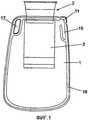
фиг.1 - пакет для сбора текучей среды согласно предпочтительному варианту выполнения изобретения;figure 1 - bag for collecting fluid according to a preferred embodiment of the invention;
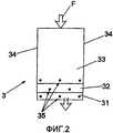
фиг.2 - система гибких пленок в средстве невозвратного клапана;figure 2 - system of flexible films in a non-return valve;
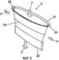
фиг.3 - фланец входа согласно изобретению в изометрической проекции;figure 3 - inlet flange according to the invention in isometric projection;
фиг.4 - фланец входа согласно фиг.3 в изометрической проекции снизу; иfigure 4 - inlet flange according to figure 3 in an isometric view from below; and
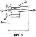
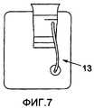
фиг.5-7 - три варианта выполнения пакета для сбора текучей среды, согласно изобретению, с выпускным средством.5-7 are three embodiments of a fluid collection bag according to the invention with an outlet means.
На фиг.1 показан пакет для сбора текучей среды согласно предпочтительному варианту выполнения изобретения. Пакет содержит мешок 1, фланец 2 входного отверстия и гибкую пленочную систему 3, образующую средство невозвратного клапана, обеспечивающее невозможность выхода текучей среды, которая протекает через вход 2 в мешок 1, через пленочную систему 3. Пленочная система 3 установлена непосредственно под входным фланцем 2 и проходит в мешок 1, как показано на фиг.1.1 shows a fluid collection bag according to a preferred embodiment of the invention. The package includes a
В мешке 1 образовано небольшое отделение 16 и отрывная полоса 11, обеспечивающая средство для выпуска текучей среды в верхнем углу вблизи центрально расположенного входного фланца 2. В зоне противоположного верхнего угла мешка 1 предусмотрено отверстие 17, например, для подвешивания пакета для сбора мочи на крючок или т.п. или для удерживания пакета во время заполнения и сливания текучей среды.A
Мешок 1 включает два гибких пленочных слоя, например, два имеющих идентичную форму пленочных листа, как показано на фиг.1, или одну пленку, которая сложена. Пленки снабжены сварочным швом 18 вдоль периферии мешка 1. Пленочная система 3 в качестве невозвратного клапана приварена или соединена постоянно другим способом с входным фланцем 2. Затем входной фланец 2 помещается между пленочными слоями, образующими мешок, и сваривается с пленочным слоем с образованием входа мешка 1.
Невозвратная клапанная пленочная система 3 не приваривается к сторонам мешка, как в предшествующем уровне техники, а проходит от входного фланца в отделение для текучей среды мешка. Невозвратный клапан 3, показанный на фиг.2, выполнен из шести гибких пленочных слоев, образующих три пары слоев 31, 32, 33, при этом пленочные слои 31, 32, 33 сварены вдоль своих сторон 34 и имеют точечную сварку 35 на дальнем конце пленочной системы с образованием направленного пути F потока через гибкую пленочную невозвратную клапанную систему 3. В этом варианте выполнения внутренние пленочные слои могут быть предусмотрены с длиной 10 см, при этом пара средних пленочных слоев имеет длину 13 см, а самые наружные слои имеют длину 14 см. Материалом пленки может быть PELD, который является полиэтиленом низкой плотности, который является прозрачным, мягким и очень гибким. Однако понятно, что можно использовать гибкие пленочные материалы других типов, включая как однослойные, так и многослойные материалы. Входной фланец выполнен из относительно жесткого пластмассового материала.The non-return
Точечная сварка 35 предусмотрена в один или более рядов, и самый нижний ряд может проходить по всему поперечному пути, а также соединять самые наружные пленки 31 невозвратного клапана с пленками пакета, образующими мешок 1.
Входной фланец 2 показан более детально на фиг.3 и 4. Входной фланец 2 расположен в центральной части пакета для сбора мочи, как показано на фиг.1. Входной фланец 2 выполнен из упругого пластмассового материала и в основном с плоской конфигурацией, которая открывается при приложении давления к боковым кромкам, как указано стрелками Р. За счет этого две боковые части 23 изгибаются наружу и создают проход, обеспечивающий прохождение потока F через входное отверстие. Самая наружная периферия 23 может быть снабжена вырезом 24 на двух угловых кромках для исключения коробления сторон 23 входного фланца при открывании входного фланца 2 посредством приложения направленного внутрь давления Р к складкам.The
Как показано на фиг.3, фланец 2 входного отверстия предпочтительно отлит с имеющей эллиптическую форму наружной концевой периферией 21 и в основном плоской открываемой внутренней концевой периферией 22.As shown in FIG. 3, the
Как указывалось выше применительно к фиг.1, в углу мешка может быть предусмотрена отрывная полоса 11 для обеспечения выпускного отверстия. Как показано на фиг.5, в другом варианте выполнения может быть предусмотрено несколько по существу конгруэнтно выполненных отрывных полос 11а, 11b, 11с в угловой зоне для обеспечения нескольких возможных размеров выпускного отверстия.As indicated above with reference to FIG. 1, a
Другие варианты выполнения выпускного средства в пакете для сбора текучей среды согласно изобретению показаны на фиг.6 и 7. Например, как показано на фиг.6, выпускное средство может включать отрывные средства 12 для разрушения невозвратного клапана 3, поскольку предусмотрены две точки 15 сварки, соединяющие гибкий невозвратный клапан 3 с пленкой мешка. Другой вариант выполнения показан на фиг.7, где отрывная полоса 13 предусмотрена в мешке 1 для обеспечения обхода невозвратного клапана 3 и обеспечения вытекания собранной текучей среды из отделения сбора текучей среды к входному отверстию 1.Other embodiments of the outlet means in the fluid collection bag according to the invention are shown in FIGS. 6 and 7. For example, as shown in FIG. 6, the outlet means may include tear-off means 12 for breaking the
Описание изобретения было приведено выше применительно к некоторым предпочтительным вариантам выполнения. Однако понятно, что могут быть предусмотрены другие варианты выполнения и изменения пакета для сбора текучей среды без выхода за объем изобретения, заданный прилагаемой формулой изобретения.A description of the invention has been given above with reference to some preferred embodiments. However, it is understood that other embodiments and modifications of the fluid collection bag may be provided without departing from the scope of the invention as defined by the appended claims.
Claims (21)
Translated fromRussianгибкий пленочный мешок (1), образующий отделение сбора текучей среды, фланец (2) входного отверстия, установленный на мешке (1) для обеспечения входа текучей среды в мешок (1), и средство (3) невозвратного клапана, содержащее множество гибких пленочных слоев (31, 32, 33) различной длины между фланцем (2) входного отверстия и отделением сбора текучей среды, для предотвращения выхода текучей среды из отделения сбора текучей среды, при этом указанное гибкое средство (3) невозвратного клапана проходит в отделение сбора текучей среды, отличающийся тем, что средство (3) клапана установлено непосредственно на фланце (2) входного отверстия, при этом эти пленочные слои (31, 32, 33) проходят от входного фланца и соединены вместе для задания общего направления потока в отделение для текучей среды.1. A bag for collecting fluid for use in hygiene, in particular a disposable bag for collecting urine, containing:
a flexible film bag (1) forming a fluid collection compartment, an inlet flange (2) mounted on the bag (1) to allow fluid to enter the bag (1), and a non-return valve means (3) comprising a plurality of flexible film layers (31, 32, 33) of various lengths between the inlet flange (2) of the inlet and the fluid collection compartment, in order to prevent fluid from escaping from the fluid collection compartment, wherein said flexible non-return valve means (3) extends to the fluid collection compartment, characterized in that redstvo (3) of the valve is arranged directly at the flange (2) of the inlet, wherein the film layers (31, 32, 33) extend from the inlet collar and are joined together to define a general flow direction into the fluid compartment.
Applications Claiming Priority (2)
| Application Number | Priority Date | Filing Date | Title |
|---|---|---|---|
| EP05075477.9 | 2005-02-28 | ||
| EP05075477AEP1695678B1 (en) | 2005-02-28 | 2005-02-28 | Disposable fluid collection bag for hygienic purposes |
Publications (2)
| Publication Number | Publication Date |
|---|---|
| RU2007135866A RU2007135866A (en) | 2009-04-10 |
| RU2403892C2true RU2403892C2 (en) | 2010-11-20 |
Family
ID=34938071
Family Applications (1)
| Application Number | Title | Priority Date | Filing Date |
|---|---|---|---|
| RU2007135866/14ARU2403892C2 (en) | 2005-02-28 | 2006-01-13 | Disposable fluid sanitary package |
Country Status (9)
| Country | Link |
|---|---|
| EP (2) | EP1695678B1 (en) |
| AT (2) | ATE369103T1 (en) |
| DE (2) | DE602005001925T2 (en) |
| DK (2) | DK1695678T3 (en) |
| ES (2) | ES2292046T3 (en) |
| NO (1) | NO20073562L (en) |
| PL (2) | PL1695678T3 (en) |
| RU (1) | RU2403892C2 (en) |
| WO (1) | WO2006089600A1 (en) |
Cited By (1)
| Publication number | Priority date | Publication date | Assignee | Title |
|---|---|---|---|---|
| WO2016042380A2 (en) | 2014-09-15 | 2016-03-24 | Ooo "Paritet" | Urine-collecting bottle for children |
Families Citing this family (13)
| Publication number | Priority date | Publication date | Assignee | Title |
|---|---|---|---|---|
| GB2441114A (en)* | 2006-08-26 | 2008-02-27 | Unomedical As | Disposable fluid collection bag for hygienic purposes having welded foil non return valve |
| CN103054505A (en)* | 2013-01-17 | 2013-04-24 | 周峰 | Environment-friendly urinating bag |
| CN103110389A (en)* | 2013-01-17 | 2013-05-22 | 周峰 | Paper bag for environmental-friendly urine bag |
| CN103054504A (en)* | 2013-01-17 | 2013-04-24 | 周峰 | Multifunctional urine bag |
| CN103054506A (en)* | 2013-01-17 | 2013-04-24 | 周峰 | Urine bag for environment-friendly urine bags |
| DE102013015966A1 (en) | 2013-09-25 | 2015-03-26 | Human Nutrition Gmbh | Privacy screen for sanitary bag |
| EP3065677B1 (en) | 2013-11-07 | 2018-06-06 | Coloplast A/S | A urine bag with an anti-reflux valve |
| FR3024439B1 (en)* | 2014-07-29 | 2017-07-21 | M3At Sa | POCKET HAVING A SAFETY VALVE |
| AU2018368738B2 (en) | 2017-11-17 | 2024-04-18 | Hollister Incorporated | Receptacles having tear-controlling features |
| EP3773366A1 (en)* | 2018-04-09 | 2021-02-17 | Swiss Safe Collect SA | Pouch comprising a safety valve and a detachable sample holder |
| US12342986B2 (en)* | 2020-08-15 | 2025-07-01 | Waihong Chung | Device for collection of excess fluids from an endoscope |
| FR3127391B1 (en)* | 2021-09-28 | 2023-11-17 | Swiss Safe Collect Sa | Liquid collection device |
| US20250114231A1 (en)* | 2021-09-29 | 2025-04-10 | C. R. Bard, Inc. | Urinary Catheter System |
Citations (4)
| Publication number | Priority date | Publication date | Assignee | Title |
|---|---|---|---|---|
| US4990145A (en)* | 1989-02-07 | 1991-02-05 | Gkr Industries, Inc. | Disposable bag with hand protection |
| US5569225A (en)* | 1995-06-29 | 1996-10-29 | Gkr Industries, Inc. | Bodily fluid test kit and method of testing bodily fluids |
| RU2080852C1 (en)* | 1990-09-12 | 1997-06-10 | Американ Иннотек, Инк. | E device |
| GB2336830A (en)* | 1998-04-29 | 1999-11-03 | Bristol Myers Squibb Co | Pyramid Drainage Bag |
Family Cites Families (2)
| Publication number | Priority date | Publication date | Assignee | Title |
|---|---|---|---|---|
| EP0847742B1 (en)* | 1996-12-12 | 2000-01-26 | Benoít Cailleteau | Flexible pouch with opening sleeve |
| GB2390547B (en)* | 2003-04-29 | 2004-07-28 | Mentor Medical Ltd | Medical waste collection device |
- 2005
- 2005-02-28DKDK05075477Tpatent/DK1695678T3/enactive
- 2005-02-28EPEP05075477Apatent/EP1695678B1/ennot_activeExpired - Lifetime
- 2005-02-28ESES05075477Tpatent/ES2292046T3/ennot_activeExpired - Lifetime
- 2005-02-28DEDE602005001925Tpatent/DE602005001925T2/ennot_activeExpired - Lifetime
- 2005-02-28ATAT05075477Tpatent/ATE369103T1/enactive
- 2005-02-28PLPL05075477Tpatent/PL1695678T3/enunknown
- 2006
- 2006-01-13DEDE602006016238Tpatent/DE602006016238D1/enactiveActive
- 2006-01-13ESES06700953Tpatent/ES2350793T3/enactiveActive
- 2006-01-13WOPCT/EP2006/000378patent/WO2006089600A1/enactiveApplication Filing
- 2006-01-13EPEP06700953Apatent/EP1855628B1/ennot_activeNot-in-force
- 2006-01-13ATAT06700953Tpatent/ATE477773T1/ennot_activeIP Right Cessation
- 2006-01-13PLPL06700953Tpatent/PL1855628T3/enunknown
- 2006-01-13RURU2007135866/14Apatent/RU2403892C2/ennot_activeIP Right Cessation
- 2006-01-13DKDK06700953.0Tpatent/DK1855628T3/enactive
- 2007
- 2007-07-09NONO20073562Apatent/NO20073562L/ennot_activeApplication Discontinuation
Patent Citations (4)
| Publication number | Priority date | Publication date | Assignee | Title |
|---|---|---|---|---|
| US4990145A (en)* | 1989-02-07 | 1991-02-05 | Gkr Industries, Inc. | Disposable bag with hand protection |
| RU2080852C1 (en)* | 1990-09-12 | 1997-06-10 | Американ Иннотек, Инк. | E device |
| US5569225A (en)* | 1995-06-29 | 1996-10-29 | Gkr Industries, Inc. | Bodily fluid test kit and method of testing bodily fluids |
| GB2336830A (en)* | 1998-04-29 | 1999-11-03 | Bristol Myers Squibb Co | Pyramid Drainage Bag |
Cited By (2)
| Publication number | Priority date | Publication date | Assignee | Title |
|---|---|---|---|---|
| WO2016042380A2 (en) | 2014-09-15 | 2016-03-24 | Ooo "Paritet" | Urine-collecting bottle for children |
| DE212015000220U1 (en) | 2014-09-15 | 2017-04-20 | Ooo "Paritet" | Children Urinflasche |
Also Published As
| Publication number | Publication date |
|---|---|
| WO2006089600A1 (en) | 2006-08-31 |
| NO20073562L (en) | 2007-11-22 |
| PL1855628T3 (en) | 2011-02-28 |
| DK1695678T3 (en) | 2007-12-27 |
| ATE477773T1 (en) | 2010-09-15 |
| EP1855628A1 (en) | 2007-11-21 |
| DE602005001925D1 (en) | 2007-09-20 |
| DK1855628T3 (en) | 2010-12-06 |
| RU2007135866A (en) | 2009-04-10 |
| PL1695678T3 (en) | 2007-12-31 |
| DE602005001925T2 (en) | 2008-04-17 |
| ES2350793T3 (en) | 2011-01-27 |
| DE602006016238D1 (en) | 2010-09-30 |
| EP1855628B1 (en) | 2010-08-18 |
| ES2292046T3 (en) | 2008-03-01 |
| EP1695678A1 (en) | 2006-08-30 |
| EP1695678B1 (en) | 2007-08-08 |
| ATE369103T1 (en) | 2007-08-15 |
Similar Documents
| Publication | Publication Date | Title |
|---|---|---|
| RU2403892C2 (en) | Disposable fluid sanitary package | |
| US20210068794A1 (en) | Pouch comprising a safety valve and a detachable sample holder | |
| JP7066301B2 (en) | Drainage ostomy pouch | |
| US4188989A (en) | Fluid collection receptacle | |
| JP5486134B2 (en) | Disposable ostomy bag | |
| RU2422342C1 (en) | Film bag | |
| RU2420322C2 (en) | Fluid removal device, bag and method for fluid removal in patient | |
| US6800088B1 (en) | Multicompartment ice bag for single patient use | |
| US4988343A (en) | Drainable pouch for collecting excretions from the human body | |
| JP5925795B2 (en) | Liquid waste collection pouch | |
| JP2006502764A5 (en) | ||
| US5048683A (en) | Sponge counter bag | |
| US5833058A (en) | Safety bags for fluid sample containers | |
| US9539158B2 (en) | Liquid sequestration bag with pinch closure | |
| US20070233032A1 (en) | Disposable diaper changing kit | |
| GB2336830A (en) | Pyramid Drainage Bag | |
| US8562578B2 (en) | Drainable pouch | |
| US20090198151A1 (en) | Urine collection device | |
| GB2441114A (en) | Disposable fluid collection bag for hygienic purposes having welded foil non return valve | |
| FI91053B (en) | Pouch means for collecting and / or storing liquid or at least predominantly liquid substances | |
| KR101083460B1 (en) | Urine Collection Container | |
| JP7739077B2 (en) | Storage bag | |
| EP4251103B1 (en) | Ostomy product with anti-reflux device | |
| DK178745B1 (en) | Container for fluids | |
| WO2024110567A1 (en) | Waste pouch for biological waste, such as immunoassay waste |
Legal Events
| Date | Code | Title | Description |
|---|---|---|---|
| MM4A | The patent is invalid due to non-payment of fees | Effective date:20120114 |