RU2399536C1 - Steering linkage trapezoid - Google Patents
Steering linkage trapezoidDownload PDFInfo
- Publication number
- RU2399536C1 RU2399536C1RU2009108155/11ARU2009108155ARU2399536C1RU 2399536 C1RU2399536 C1RU 2399536C1RU 2009108155/11 ARU2009108155/11 ARU 2009108155/11ARU 2009108155 ARU2009108155 ARU 2009108155ARU 2399536 C1RU2399536 C1RU 2399536C1
- Authority
- RU
- Russia
- Prior art keywords
- intermediate element
- clamp
- tips
- split intermediate
- split
- Prior art date
Links
- 230000001681protective effectEffects0.000claimsabstractdescription29
- 230000008878couplingEffects0.000claimsabstractdescription18
- 238000010168coupling processMethods0.000claimsabstractdescription18
- 238000005859coupling reactionMethods0.000claimsabstractdescription18
- 230000007246mechanismEffects0.000abstractdescription2
- 208000005408Metatarsus VarusDiseases0.000abstract1
- 230000000694effectsEffects0.000abstract1
- 239000000126substanceSubstances0.000abstract1
- 238000000034methodMethods0.000description8
- 238000005260corrosionMethods0.000description4
- 230000007797corrosionEffects0.000description4
- 238000009825accumulationMethods0.000description3
- 239000004519greaseSubstances0.000description3
- 239000000356contaminantSubstances0.000description2
- 238000009434installationMethods0.000description2
- 230000001105regulatory effectEffects0.000description2
- 241000826860TrapeziumSpecies0.000description1
- 230000033228biological regulationEffects0.000description1
- 230000001276controlling effectEffects0.000description1
- 230000014759maintenance of locationEffects0.000description1
- 239000000725suspensionSubstances0.000description1
Images


Landscapes
- Steering-Linkage Mechanisms And Four-Wheel Steering (AREA)
Abstract
Description
Translated fromRussianИзобретение относится к области машиностроения, а именно к тягам рулевой трапеции автомобилей с рулевым механизмом реечного типа.The invention relates to the field of engineering, namely to traction steering trapezoid of vehicles with rack and pinion steering gear.
У переднеприводных легковых автомобилей с передней подвеской Макферсон в наиболее распространенных видах реечных рулевых механизмов конструкция тяги рулевой трапеции, как правило, содержит наружный и внутренний наконечники, связанные соответственно промежуточным элементом посредством резьб противоположного направления. Промежуточный элемент имеет в средней части поверхность под ключ, а наконечники выполнены с разрезным корпусом в области резьбовой части хвостовика, имеющим хомут, выполненный за одно целое с хвостовиком корпуса наконечника в виде приливов, расположенных по обеим сторонам от прорези (Раймпель Й. Шасси автомобиля. Рулевое управление. М.: Машиностроение, 1987, с.72-74, рис.3.14).In front-wheel drive cars with MacPherson strut front suspension, in the most common types of rack and pinion steering gears, the steering trapezium thrust design typically contains outer and inner tips connected respectively by an intermediate element through threads in the opposite direction. The intermediate element has a turnkey surface in the middle part, and the tips are made with a split body in the area of the threaded part of the shank, having a clamp made in one piece with the shank of the tip body in the form of tides located on both sides of the slot (Raimpel J. Chassis of the car. Steering, Moscow: Mashinostroenie, 1987, pp. 72-74, Fig. 3.14).
Одна из основных функций тяги рулевой трапеции - это регулирование схождения колес. В конструкциях переднеприводных легковых автомобилей регулирование схождения колес производят путем изменения длины тяг за счет вращения промежуточного элемента. Стопорение промежуточного элемента относительно наконечников обеспечивают при помощи двух стяжных болтов через хомуты наконечников.One of the main functions of the steering trapezoid traction is the regulation of the convergence of the wheels. In the designs of front-wheel drive cars, the toe-in is regulated by changing the length of the rods due to the rotation of the intermediate element. The locking of the intermediate element relative to the tips is provided with two coupling bolts through the clamps of the tips.
К недостаткам известной конструкции тяги рулевой трапеции можно отнести повышенные трудозатраты, вызванные затруднениями в проведении процесса регулировок схождения колес из-за относительно больших габаритов регулировочных узлов по длине, расположенных в ограниченном для доступа к тягам пространстве в зоне арок колес.The disadvantages of the known design of traction of the steering trapezoid include increased labor costs caused by difficulties in the process of adjusting the toe of the wheels due to the relatively large dimensions of the adjustment nodes in length, located in a limited space for access to the rods in the area of the wheel arches.
Известна тяга рулевой трапеции, состоящая из двух наконечников - наружного и внутреннего, связанных соответственно разрезным промежуточным элементом посредством резьб противоположного направления. Стопорение промежуточного элемента относительно наконечников обеспечивают при помощи стяжных болтов и гаек через два хомута, расположенных на наружной поверхности разрезного промежуточного элемента (Раймпель И. Шасси автомобиля. Рулевое управление. М.: Машиностроение, 1987, с.78, рис.3.22).Known thrust steering trapezoid, consisting of two tips - external and internal, respectively connected by a split intermediate element through threads in the opposite direction. The locking of the intermediate element relative to the tips is ensured by means of coupling bolts and nuts through two clamps located on the outer surface of the split intermediate element (Raimpel I. Chassis of the automobile. Steering. M .: Mashinostroenie, 1987, p. 78, Fig. 3.22).
Однако известная тяга рулевой трапеции при своем использовании имеет следующие недостатки:However, the known traction of the steering trapezoid during its use has the following disadvantages:
- сложность проведения процесса регулировок схождения колес,- the complexity of the process of adjusting the toe,
- высокая сложность осуществления стопорения промежуточного элемента относительно рулевых наконечников стяжными болтами и гайками в случае ограниченного доступа к регулировочным узлам тяги.- the high complexity of locking the intermediate element relative to the steering tips with tie bolts and nuts in case of limited access to the thrust adjustment nodes.
Наиболее близким к заявляемому объекту по технической сущности из известных решений является телескопическая тяга рулевой трапеции, содержащая наружный и внутренний наконечники, связанные соответственно с разрезным промежуточным элементом посредством резьб противоположного направления, и хомут с отверстием под поперечный стяжной болт, при этом на промежуточном элементе выполнен разрез и поверхность под ключ (см. патент РФ №2016802, МПК B62D 7/20,1994 г.).The closest to the claimed object according to the technical essence of the known solutions is the telescopic steering trapezoidal rod, containing the outer and inner lugs, respectively connected with a split intermediate element by means of threads in the opposite direction, and a clamp with a hole for the transverse coupling bolt, while an intermediate element is made in the section and turnkey surface (see RF patent No. 2016802, IPC B62D 7 / 20,1994).
Однако известная тяга рулевой трапеции при своем использовании имеет следующие недостатки:However, the known traction of the steering trapezoid during its use has the following disadvantages:
- затруднения в проведении процесса регулировок схождения колес после определенного периода процесса эксплуатации,- difficulties in the process of adjusting the toe-in after a certain period of the operation process,
- накопление продуктов коррозии и загрязнений в резьбе втулки и наконечников,- accumulation of corrosion products and contaminants in the thread of the sleeve and lugs,
- ограниченный ресурс эксплуатации.- limited service life.
Задачей изобретения является создание тяги рулевой трапеции.The objective of the invention is the creation of traction steering trapezoid.
Техническим результатом при использовании предложенной тяги рулевой трапеции является отсутствие затруднений в проведении процесса регулировок схождения колес после определенного периода процесса эксплуатации, повышение надежности стопорения промежуточного элемента относительно рулевых наконечников стяжными болтами при ограниченном доступе к регулировочным узлам тяги, предотвращение накопления продуктов коррозии и загрязнений в резьбовых соединениях втулки и наконечников, а также повышение ресурса эксплуатации.The technical result when using the proposed steering trapezoidal traction is the absence of difficulties in the process of adjusting the toe-in after a certain period of the operation process, increasing the reliability of locking the intermediate element relative to the steering tips with tightening bolts with limited access to the thrust adjusting nodes, and preventing the accumulation of corrosion products and dirt in threaded joints bushings and tips, as well as increasing the service life.
Технический результат при осуществлении изобретения достигается тем, что предложена тяга рулевой трапеции, содержащая наружный и внутренний наконечники, связанные соответственно с разрезным промежуточным элементом посредством резьб противоположного направления, и хомут с отверстием под поперечный стяжной болт, а на промежуточном элементе выполнен разрез и поверхность под ключ, при этом внутренний и наружный наконечники выполнены с резьбовыми участками, имеющими наружные резьбы противоположного друг другу направления, разрезной промежуточный элемент выполнен в виде втулки с последовательно расположенными резьбовыми участками, имеющими внутренние резьбы, посредством которых он связан с соответствующими резьбовыми участками внутреннего и наружного наконечников, при этом разрезной промежуточный элемент по наружному диаметру охватывает защитный кожух, имеющий разрез, а хомут выполнен за одно целое с защитным кожухом. При этом разрезной промежуточный элемент выполнен с кольцевой проточкой в центральной части наружной цилиндрической поверхности. При этом разрезной промежуточный элемент выполнен с кольцевым выступом на наружной цилиндрической поверхности со стороны, противоположной поверхности под ключ. При этом хомут выполнен за одно целое с защитным кожухом посредством приливов хомута, расположенных по обеим краям его прорези. При этом приливы хомута выполнены шириной по всей длине прорези защитного кожуха. При этом оси отверстий под стяжной болт на приливах хомута выполнены со смещением к одной из торцевых сторон защитного кожуха.The technical result in the implementation of the invention is achieved by the fact that the proposed traction of the steering trapezoid, containing the outer and inner lugs, respectively connected with a split intermediate element by means of threads of the opposite direction, and a clamp with a hole for the transverse coupling bolt, and on the intermediate element is made a cut and a turnkey surface while the inner and outer lugs are made with threaded sections having external threads of opposite directions to each other, a split pr the intermediate element is made in the form of a sleeve with successively threaded portions having internal threads, by means of which it is connected with the corresponding threaded sections of the inner and outer tips, while the split intermediate element extends around the outer diameter of the protective casing having a cut, and the clamp is made in one piece with a protective cover. When this split intermediate element is made with an annular groove in the Central part of the outer cylindrical surface. In this case, the split intermediate element is made with an annular protrusion on the outer cylindrical surface from the side opposite the turnkey surface. In this case, the clamp is made in one piece with the protective casing by means of the tides of the clamp located on both edges of its slot. In this case, the collar tides are made wide along the entire length of the slot of the protective casing. In this case, the axis of the holes for the coupling bolt at the tide of the clamp is made with an offset to one of the end sides of the protective casing.
Среди признаков, характеризующих предложенную тягу рулевой трапеции, существенными являются:Among the signs characterizing the proposed traction of the steering trapezoid, the essential ones are:
- выполнение внутреннего и наружного наконечников с резьбовыми участками, имеющими наружные резьбы противоположного друг другу направления,- the implementation of the inner and outer lugs with threaded sections having external threads of opposite directions to each other,
- выполнение разрезного промежуточного элемента в виде втулки с последовательно расположенными резьбовыми участками, имеющими внутренние резьбы, посредством которых промежуточный элемент связан с соответствующими резьбовыми участками внутреннего и наружного наконечников,- the implementation of a split intermediate element in the form of a sleeve with sequentially threaded sections having internal threads, through which the intermediate element is connected with the corresponding threaded sections of the inner and outer tips,
- разрезной промежуточный элемент по наружному диаметру охватывает защитный кожух, имеющий разрез,- split intermediate element on the outer diameter covers a protective casing having a cut,
- выполнение хомута за одно целое с защитным кожухом,- the execution of the clamp in one piece with a protective casing,
- выполнение разрезного промежуточного элемента с кольцевой проточкой в центральной части наружной цилиндрической поверхности,- the implementation of a split intermediate element with an annular groove in the Central part of the outer cylindrical surface,
- выполнение разрезного промежуточного элемента с кольцевым выступом на наружной цилиндрической поверхности со стороны, противоположной поверхности под ключ,- the implementation of a split intermediate element with an annular protrusion on the outer cylindrical surface from the side opposite the turnkey surface,
- выполнение хомута за одно целое с защитным кожухом посредством приливов хомута, расположенных по обоим краям его прорези,- the execution of the clamp in one piece with a protective casing by means of tides of the clamp located on both edges of its slot,
- выполнение приливов хомута шириной по всей длине прорези защитного кожуха,- the implementation of the tides of the clamp width along the entire length of the slots of the protective casing,
- выполнение оси отверстий под стяжной болт на приливах хомута со смещением к одной из торцевых сторон защитного кожуха.- the execution of the axis of the holes for the coupling bolt on the tides of the clamp with an offset to one of the end sides of the protective casing.
Экспериментальные исследования предложенной тяги рулевой трапеции показали ее высокую эффективность. Было установлено, что предложенная тяга рулевой трапеции обладает отсутствием затруднений в проведении процесса регулировок схождения колес после определенного периода процесса эксплуатации, имеет повышенную на 15-18% надежность стопорения промежуточного элемента относительно рулевых наконечников стяжными болтами при ограниченном доступе к регулировочным узлам тяги. Кроме того, предложенная тяга рулевой трапеции предотвращает накопление продуктов коррозии и загрязнений в резьбовых соединениях втулки и наконечников, а также обладает повышенным на 18% ресурсом эксплуатации.Experimental studies of the proposed traction steering trapezoid showed its high efficiency. It was found that the proposed steering trapezoidal thrust has no difficulties in the process of adjusting the toe-in after a certain period of the operation process, has a 15-18% increased reliability of locking the intermediate element relative to the steering tips with tie bolts with limited access to the thrust adjusting nodes. In addition, the proposed draft of the steering trapezoid prevents the accumulation of corrosion products and contaminants in the threaded joints of the sleeve and tips, and also has an increased service life of 18%.
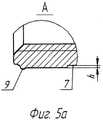
Сущность предложенного технического решения поясняется чертежами, где на фиг.1 показан общий вид предложенной тяги рулевой трапеции, на фиг.2 - продольный разрез тяги рулевой трапеции, на фиг.3 - разрез А-А на фиг.2, на фиг.4 - разрез Б-Б на фиг.2, на фиг.5 - продольный разрез разрезного промежуточного элемента и на фиг.5а - выносной элемент разрезного промежуточного элемента.The essence of the proposed technical solution is illustrated by drawings, in which Fig. 1 shows a general view of the proposed thrust of the steering trapezoid, Fig. 2 is a longitudinal section of the thrust of the steering trapezoid, in Fig. 3 is a section AA in Fig. 2, in Fig. 4 - section B-B in figure 2, figure 5 is a longitudinal section of a split intermediate element and figure 5A is a remote element of a split intermediate element.
Тяга рулевой трапеции левая (правая тяга симметричное отображение левой) состоит из наружного наконечника 1, который своим свободным концом связан с поворотной стойкой (не показана) колеса автомобиля. Другой конец наружного наконечника 1 выполнен в виде хвостовика с наружной резьбой и ввернут по резьбе в разрезной промежуточный элемент 3. С противоположной стороны разрезного промежуточного элемента 3 ввернут по резьбе внутренний наконечник 2, выполненный в виде хвостовика с наружной резьбой. Другой конец внутреннего наконечника 2 соединен с зубчатой рейкой рулевого механизма (на фиг.1 не показана). Разрезной промежуточный элемент 3 по наружному диаметру охватывает защитный кожух 4, имеющий разрез 11 (фиг.3), и хомут, выполненный за одно целое с защитным кожухом посредством приливов хомута 10 (фиг.2 и 3), расположенных по обеим краям его прорези 11, имеющих отверстия (одно из них резьбовое) под стяжной болт 5.The left steering link traction (the right link is the left symmetrical display) consists of an
Промежуточный элемент 3 выполнен в виде втулки с последовательно расположенными резьбовыми участками, имеющими внутренние резьбы противоположного друг другу направления, посредством которых он связан с соответствующими резьбовыми участками наружного 1 и внутреннего 2 наконечников. По всей длине боковой поверхности промежуточного элемента 3 выполнена прорезь 6 (фиг.3 и 4). Разрезной промежуточный элемент 3 выполнен с кольцевой проточкой 7 (фиг.5) в центральной части наружной цилиндрической поверхности на участке L, обеспечивающей не только снижение усилия стягивания хомута, но и повышения эффективности стопорения разрезным промежуточным элементом 3 резьбовой части хвостовиков наружного 1 и внутреннего 2 наконечников. На одном из концов разрезного промежуточного элемента 3 выполнена поверхность 8 (фиг.4 и 5) под ключ, позволяющая проводить регулировку углов схождения ведущих колес автомобиля (поверхность под ключ может быть выполнена, как показано на фиг.1-2, со стороны внутреннего наконечника, в частном случае поверхность под ключ может быть выполнена со стороны наружного наконечника). С противоположной стороны разрезного промежуточного элемента 3 выполнен кольцевой выступ 9 (фиг.5 и 5 а), обеспечивающий удержание защитного кожуха 4 на промежуточном элементе 3 при транспортировке и монтаже тяги на автомобиль (в частном случае при отсутствии кольцевого выступа 9 функции удержания защитного кожуха 4 на промежуточном элементе 3 при транспортировке и монтаже тяги на автомобиль могут выполнять кольцевая проточка 7 и стяжной болт 5).The
Для обеспечения необходимой жесткости хомута при контрении резьбовых хвостовиков наконечников 1 и 2 в разрезном промежуточном элементе 3 приливы хомута 10 выполнены по длине защитного чехла L1. Для обеспечения гарантированного зазора между наиболее выступающей части приливов 10 хомута в области отверстий под стяжной болт 5 относительно оси промежуточного элемента 3 и другими элементами автомобиля, расположенными в ограниченном пространстве арки, оси отверстий под стяжной болт на приливах хомута выполнены со смещением к одной из торцевых сторон защитного кожуха, т.е. частный случай L2≠L1.To ensure the necessary rigidity of the clamp when controlling the threaded shanks of the
Устройство работает следующим образом. Перед началом регулировки длины тяги расстопаривают узел регулировки, ослабляя стяжной болт 5. Изменение длины тяги производят вращением разрезного промежуточного элемента 3 в том или ином направлении. За счет того, что внутренний и наружный наконечники выполнены с резьбовыми участками, имеющими наружные резьбы противоположного друг другу направления, а разрезной промежуточный элемент выполнен в виде втулки с последовательно расположенными резьбовыми участками, имеющими внутренние резьбы, посредством которых он связан с соответствующими резьбовыми участками внутреннего и наружного наконечников, при вращении разрезного промежуточного элемента 3 в том или ином направлении концы наружного и внутреннего наконечников сходятся или расходятся. Изменением длины тяг левой и правой регулируют углы схождения ведущих колес автомобиля. После выставления необходимых углов схождения колес повернуть защитный кожух 4 таким образом, чтобы он своим корпусом перекрыл прорезь 6 разрезного промежуточного элемента 3, при этом головка стяжного болта была доступна для закручивания. Затягиванием стяжного болта 5 произвести стопорение наконечников 1 и 2 в разрезном промежуточном элементе 3.The device operates as follows. Before starting the adjustment of the rod length, the adjustment unit is opened by loosening the
В частном случае для предотвращения попадания влаги в регулирующее устройство тяги полость между защитным кожухом 4 и разрезным промежуточным элементом 3 в области проточки 7, а так же прорези с торцов промежуточного элемента 3 заполняют смазкой.In the particular case, to prevent moisture from entering the traction control device, the cavity between the
В случае попадания влаги и коррозии резьбы в области регулирующего устройства тяги его достаточно просто разобрать. Для этого ослабляется и (при необходимости) удаляется стяжной болт 5. Поскольку защитный кожух и хомут не имеют ребер жесткости, достаточно развести приливы хомута, чтобы сдвинуть его (при необходимости) с разрезного промежуточного элемента 3. Прокручиванием разрезного промежуточного элемента 3 добиваются регулировки схождения колес. Поскольку разрезной промежуточный элемента 3 имеет сквозную прорезь, при необходимости можно слегка развести его в области прорези и провернуть. Далее, выкрутив наконечники 1 и 2, нанести на резьбу смазку и закрутить их обратно. Поставив на место защитный кожух 4 и стяжной болт 5, провести регулировку углов схождения ведущих колес и стопорение узла регулировки.In case of moisture ingress and corrosion of the thread in the area of the traction control device, it is enough to disassemble it. To do this, the
В сравнении с прототипом предложенная тяга рулевой трапеции при той же быстроте и точности регулировки легко устанавливается и демонтируется даже при коррозии резьбовых соединений, что позволяет обеспечить регулировку углов схождения колес автомобиля в течение всего ресурса ее эксплуатации. Защитный кожух и смазка ограничивают попадание влаги в регулировочный узел тяги. В случае повреждения защитного узла при монтаже его всегда можно заменить, оставив работоспособные наконечники.Compared with the prototype, the proposed steering trapezoidal thrust with the same speed and accuracy of adjustment is easily installed and dismantled even when the threaded joints are corroded, which makes it possible to adjust the convergence angles of the vehicle’s wheels throughout its entire service life. The protective cover and grease limit the ingress of moisture into the traction control assembly. In case of damage to the protective assembly during installation, it can always be replaced, leaving operable tips.
Предлагаемую конструкцию рулевой тяги можно применять в рулевых системах автомобилей с задним и передним приводом.The proposed design of the steering rod can be used in the steering systems of cars with rear and front wheel drive.
Claims (4)
Translated fromRussianPriority Applications (1)
| Application Number | Priority Date | Filing Date | Title |
|---|---|---|---|
| RU2009108155/11ARU2399536C1 (en) | 2009-03-10 | 2009-03-10 | Steering linkage trapezoid |
Applications Claiming Priority (1)
| Application Number | Priority Date | Filing Date | Title |
|---|---|---|---|
| RU2009108155/11ARU2399536C1 (en) | 2009-03-10 | 2009-03-10 | Steering linkage trapezoid |
Publications (1)
| Publication Number | Publication Date |
|---|---|
| RU2399536C1true RU2399536C1 (en) | 2010-09-20 |
Family
ID=42939093
Family Applications (1)
| Application Number | Title | Priority Date | Filing Date |
|---|---|---|---|
| RU2009108155/11ARU2399536C1 (en) | 2009-03-10 | 2009-03-10 | Steering linkage trapezoid |
Country Status (1)
| Country | Link |
|---|---|
| RU (1) | RU2399536C1 (en) |
Cited By (2)
| Publication number | Priority date | Publication date | Assignee | Title |
|---|---|---|---|---|
| RU168034U1 (en)* | 2015-11-23 | 2017-01-17 | Общество С Ограниченной Ответственностью "Научно-Производственное Объединение "Ростар" | THREADED BUSHING |
| WO2019165031A1 (en)* | 2018-02-24 | 2019-08-29 | Schmidt George R | Cross tube assembly for a motor vehicle |
Citations (7)
| Publication number | Priority date | Publication date | Assignee | Title |
|---|---|---|---|---|
| US1625818A (en)* | 1925-11-11 | 1927-04-26 | Walter O Fredrikson | Turnbuckle |
| US3989394A (en)* | 1975-10-29 | 1976-11-02 | General Motors Corporation | Steering linkage adjust retainer |
| US5004367A (en)* | 1989-12-01 | 1991-04-02 | Trw Inc. | Turnbuckle assembly |
| US5172877A (en)* | 1990-08-31 | 1992-12-22 | Usui Kokusai Sangyo Kaisha Ltd. | Pipe fixing structure using clamp member |
| US5306095A (en)* | 1991-10-15 | 1994-04-26 | Trw Inc. | Vehicle steering link assembly |
| RU2016802C1 (en)* | 1990-06-07 | 1994-07-30 | Волжское объединение по производству легковых автомобилей | Steering linkage telescopic link |
| RU2045692C1 (en)* | 1990-06-18 | 1995-10-10 | Штрауб Федернфабрик АГ | Pipe coupling |
- 2009
- 2009-03-10RURU2009108155/11Apatent/RU2399536C1/ennot_activeIP Right Cessation
Patent Citations (7)
| Publication number | Priority date | Publication date | Assignee | Title |
|---|---|---|---|---|
| US1625818A (en)* | 1925-11-11 | 1927-04-26 | Walter O Fredrikson | Turnbuckle |
| US3989394A (en)* | 1975-10-29 | 1976-11-02 | General Motors Corporation | Steering linkage adjust retainer |
| US5004367A (en)* | 1989-12-01 | 1991-04-02 | Trw Inc. | Turnbuckle assembly |
| RU2016802C1 (en)* | 1990-06-07 | 1994-07-30 | Волжское объединение по производству легковых автомобилей | Steering linkage telescopic link |
| RU2045692C1 (en)* | 1990-06-18 | 1995-10-10 | Штрауб Федернфабрик АГ | Pipe coupling |
| US5172877A (en)* | 1990-08-31 | 1992-12-22 | Usui Kokusai Sangyo Kaisha Ltd. | Pipe fixing structure using clamp member |
| US5306095A (en)* | 1991-10-15 | 1994-04-26 | Trw Inc. | Vehicle steering link assembly |
Cited By (2)
| Publication number | Priority date | Publication date | Assignee | Title |
|---|---|---|---|---|
| RU168034U1 (en)* | 2015-11-23 | 2017-01-17 | Общество С Ограниченной Ответственностью "Научно-Производственное Объединение "Ростар" | THREADED BUSHING |
| WO2019165031A1 (en)* | 2018-02-24 | 2019-08-29 | Schmidt George R | Cross tube assembly for a motor vehicle |
Similar Documents
| Publication | Publication Date | Title |
|---|---|---|
| JP6963213B2 (en) | Strut suspension device | |
| RU2399536C1 (en) | Steering linkage trapezoid | |
| JP2007245843A (en) | Tie rod structure of steering device | |
| US11780504B2 (en) | Frame device for a vehicle, in particular for a motor vehicle, and vehicle having at least one such frame device | |
| US8517142B1 (en) | Power steering unit and frame assembly for supporting steering unit | |
| US4647058A (en) | Steering mechanism for motor vehicles | |
| JP2021008265A (en) | Power steering system with end stop for blocking nut integrated into reducer casing | |
| RU2397096C1 (en) | Pitman arm link | |
| JP2017024640A (en) | Joining structure of link rod of front two-axle vehicle | |
| WO2017056234A1 (en) | Bearing structure for shaft | |
| CN204296858U (en) | A kind of steering linkage assembly | |
| RU12561U1 (en) | TELESCOPIC POWER STEERING KEY | |
| KR100599699B1 (en) | Control lever of active suspension | |
| JP7298058B2 (en) | vehicle steering system | |
| JP6928308B2 (en) | Link rod and link rod end assembly | |
| JP2014101969A (en) | Yoke joint structure of universal joint | |
| RU2016802C1 (en) | Steering linkage telescopic link | |
| KR100456921B1 (en) | Tie rod of steering linkage for automobiles | |
| KR20150058688A (en) | Tie Rod Unit having Stiffness Reinforcement Connecter | |
| KR0135664Y1 (en) | Wrench for tightening nut on ball joint | |
| KR19990019905A (en) | Caster angle adjustment structure of bus with turnbuckle | |
| JP2006118556A (en) | Lock nut | |
| KR200445107Y1 (en) | Reinforcement of trailing arm suspension | |
| KR100223787B1 (en) | Tie rod of car | |
| KR200158024Y1 (en) | Bolt for fixing toe angle of car |
Legal Events
| Date | Code | Title | Description |
|---|---|---|---|
| MM4A | The patent is invalid due to non-payment of fees | Effective date:20110311 |