RU2398112C2 - Combined downhole tool for measurement of side specific resistance and specific resistance of propagation - Google Patents
Combined downhole tool for measurement of side specific resistance and specific resistance of propagationDownload PDFInfo
- Publication number
- RU2398112C2 RU2398112C2RU2005109317/03ARU2005109317ARU2398112C2RU 2398112 C2RU2398112 C2RU 2398112C2RU 2005109317/03 ARU2005109317/03 ARU 2005109317/03ARU 2005109317 ARU2005109317 ARU 2005109317ARU 2398112 C2RU2398112 C2RU 2398112C2
- Authority
- RU
- Russia
- Prior art keywords
- pipe
- protective device
- recess
- toroidal
- insulating
- Prior art date
Links
- 238000005259measurementMethods0.000titleabstractdescription31
- 230000001681protective effectEffects0.000claimsabstractdescription85
- 230000015572biosynthetic processEffects0.000claimsabstractdescription42
- 239000011810insulating materialSubstances0.000claimsdescription36
- 238000000034methodMethods0.000claimsdescription33
- 239000000463materialSubstances0.000claimsdescription19
- 230000007246mechanismEffects0.000claimsdescription18
- 238000004804windingMethods0.000claimsdescription15
- 239000000945fillerSubstances0.000claimsdescription6
- 229910000859α-FeInorganic materials0.000claimsdescription3
- 239000012777electrically insulating materialSubstances0.000claimsdescription2
- 238000005755formation reactionMethods0.000abstractdescription41
- 230000006698inductionEffects0.000abstractdescription14
- 238000004519manufacturing processMethods0.000abstractdescription6
- 230000000694effectsEffects0.000abstractdescription2
- 238000005065miningMethods0.000abstract1
- 239000000126substanceSubstances0.000abstract1
- 239000011162core materialSubstances0.000description34
- 230000005291magnetic effectEffects0.000description28
- 238000005553drillingMethods0.000description27
- 229920001971elastomerPolymers0.000description18
- 239000012530fluidSubstances0.000description18
- 239000002184metalSubstances0.000description12
- 229910052751metalInorganic materials0.000description12
- 239000011152fibreglassSubstances0.000description11
- 239000005060rubberSubstances0.000description10
- 238000013461designMethods0.000description9
- 230000005520electrodynamicsEffects0.000description9
- 239000000806elastomerSubstances0.000description8
- 230000008901benefitEffects0.000description6
- 238000010586diagramMethods0.000description6
- 238000009826distributionMethods0.000description6
- 230000035699permeabilityEffects0.000description5
- 238000005516engineering processMethods0.000description4
- 230000008569processEffects0.000description4
- 238000007789sealingMethods0.000description4
- 229910000815supermalloyInorganic materials0.000description4
- 230000005684electric fieldEffects0.000description3
- 230000004044responseEffects0.000description3
- 229920002449FKMPolymers0.000description2
- 239000004696Poly ether ether ketoneSubstances0.000description2
- JUPQTSLXMOCDHR-UHFFFAOYSA-Nbenzene-1,4-diol;bis(4-fluorophenyl)methanoneChemical compoundOC1=CC=C(O)C=C1.C1=CC(F)=CC=C1C(=O)C1=CC=C(F)C=C1JUPQTSLXMOCDHR-UHFFFAOYSA-N0.000description2
- 239000002131composite materialSubstances0.000description2
- 239000013013elastic materialSubstances0.000description2
- 238000010292electrical insulationMethods0.000description2
- 239000003822epoxy resinSubstances0.000description2
- 239000003302ferromagnetic materialSubstances0.000description2
- 229920001973fluoroelastomerPolymers0.000description2
- 230000002706hydrostatic effectEffects0.000description2
- 238000009413insulationMethods0.000description2
- 238000012423maintenanceMethods0.000description2
- 238000012544monitoring processMethods0.000description2
- 238000000465mouldingMethods0.000description2
- 230000035515penetrationEffects0.000description2
- 229920000647polyepoxidePolymers0.000description2
- 229920002530polyetherether ketonePolymers0.000description2
- 230000001012protectorEffects0.000description2
- 239000003381stabilizerSubstances0.000description2
- 238000012496stress studyMethods0.000description2
- 229920003051synthetic elastomerPolymers0.000description2
- 239000004593EpoxySubstances0.000description1
- 229910001030Iron–nickel alloyInorganic materials0.000description1
- 229920000271Kevlar®Polymers0.000description1
- -1RANDOLITE TMSubstances0.000description1
- 230000002411adverseEffects0.000description1
- 238000013459approachMethods0.000description1
- 238000005452bendingMethods0.000description1
- 229910021538boraxInorganic materials0.000description1
- 239000000919ceramicSubstances0.000description1
- 230000008859changeEffects0.000description1
- 239000011248coating agentSubstances0.000description1
- 238000000576coating methodMethods0.000description1
- 238000004891communicationMethods0.000description1
- 239000011231conductive fillerSubstances0.000description1
- 238000010276constructionMethods0.000description1
- 238000005520cutting processMethods0.000description1
- 238000001514detection methodMethods0.000description1
- 238000009792diffusion processMethods0.000description1
- 230000009977dual effectEffects0.000description1
- 238000011156evaluationMethods0.000description1
- 239000004744fabricSubstances0.000description1
- 230000005294ferromagnetic effectEffects0.000description1
- 238000011010flushing procedureMethods0.000description1
- 238000003384imaging methodMethods0.000description1
- 230000001939inductive effectEffects0.000description1
- 238000009434installationMethods0.000description1
- 238000002955isolationMethods0.000description1
- 239000004761kevlarSubstances0.000description1
- 239000007769metal materialSubstances0.000description1
- 150000002739metalsChemical class0.000description1
- 229920003052natural elastomerPolymers0.000description1
- 229920001194natural rubberPolymers0.000description1
- 229910000889permalloyInorganic materials0.000description1
- 229920006260polyaryletherketonePolymers0.000description1
- 238000011160researchMethods0.000description1
- 239000011435rockSubstances0.000description1
- 239000004328sodium tetraborateSubstances0.000description1
- 235000010339sodium tetraborateNutrition0.000description1
- 239000005061synthetic rubberSubstances0.000description1
- 239000012815thermoplastic materialSubstances0.000description1
- 238000012546transferMethods0.000description1
- 230000001960triggered effectEffects0.000description1
- XLYOFNOQVPJJNP-UHFFFAOYSA-NwaterSubstancesOXLYOFNOQVPJJNP-UHFFFAOYSA-N0.000description1
- 230000003313weakening effectEffects0.000description1
Images


Classifications
- E—FIXED CONSTRUCTIONS
- E21—EARTH OR ROCK DRILLING; MINING
- E21B—EARTH OR ROCK DRILLING; OBTAINING OIL, GAS, WATER, SOLUBLE OR MELTABLE MATERIALS OR A SLURRY OF MINERALS FROM WELLS
- E21B47/00—Survey of boreholes or wells
- E21B47/01—Devices for supporting measuring instruments on drill bits, pipes, rods or wirelines; Protecting measuring instruments in boreholes against heat, shock, pressure or the like
- E21B47/017—Protecting measuring instruments
- G—PHYSICS
- G01—MEASURING; TESTING
- G01V—GEOPHYSICS; GRAVITATIONAL MEASUREMENTS; DETECTING MASSES OR OBJECTS; TAGS
- G01V3/00—Electric or magnetic prospecting or detecting; Measuring magnetic field characteristics of the earth, e.g. declination, deviation
- G01V3/18—Electric or magnetic prospecting or detecting; Measuring magnetic field characteristics of the earth, e.g. declination, deviation specially adapted for well-logging
- G01V3/26—Electric or magnetic prospecting or detecting; Measuring magnetic field characteristics of the earth, e.g. declination, deviation specially adapted for well-logging operating with magnetic or electric fields produced or modified either by the surrounding earth formation or by the detecting device
- G—PHYSICS
- G01—MEASURING; TESTING
- G01V—GEOPHYSICS; GRAVITATIONAL MEASUREMENTS; DETECTING MASSES OR OBJECTS; TAGS
- G01V3/00—Electric or magnetic prospecting or detecting; Measuring magnetic field characteristics of the earth, e.g. declination, deviation
- G01V3/18—Electric or magnetic prospecting or detecting; Measuring magnetic field characteristics of the earth, e.g. declination, deviation specially adapted for well-logging
- G01V3/30—Electric or magnetic prospecting or detecting; Measuring magnetic field characteristics of the earth, e.g. declination, deviation specially adapted for well-logging operating with electromagnetic waves
Landscapes
- Life Sciences & Earth Sciences (AREA)
- Physics & Mathematics (AREA)
- Engineering & Computer Science (AREA)
- Geology (AREA)
- Geophysics (AREA)
- Environmental & Geological Engineering (AREA)
- General Life Sciences & Earth Sciences (AREA)
- Mining & Mineral Resources (AREA)
- Remote Sensing (AREA)
- General Physics & Mathematics (AREA)
- Electromagnetism (AREA)
- Fluid Mechanics (AREA)
- Geochemistry & Mineralogy (AREA)
- Geophysics And Detection Of Objects (AREA)
- Details Of Aerials (AREA)
- Arrangements For Transmission Of Measured Signals (AREA)
Abstract
Description
Translated fromRussianУровень техникиState of the art
Область техники, к которой относится изобретениеFIELD OF THE INVENTION
Изобретение относится в общем к области подземных исследований и добычи. Более конкретно, изобретение относится к способам и устройству для измерения свойств удельного сопротивления земных формаций при проникновении в них через скважину.The invention relates generally to the field of underground exploration and production. More specifically, the invention relates to methods and apparatus for measuring the resistivity of terrestrial formations when they enter them through a well.
Уровень техникиState of the art
Инструменты каротажа удельного сопротивления много лет использовались для измерения удельного сопротивления земных формаций, окружающих скважину. Традиционно измерения удельного сопротивления осуществлялись при опускании каротажного устройства с проводной линией связи в скважину после того, как скважина была пробурена. Тем не менее, измерения с проводной линией связи обязательно приводят к задержке между временем, когда скважина пробурена, и временем, когда получены измерения. Предпочтительным подходом является осуществление таких измерений во время процесса бурения скважины для возможности принятия корректирующих шагов, при необходимости. Например, если информация о скважине обеспечивается в реальном масштабе времени, то она может быть использована для осуществления корректировки масс бурового раствора, чтобы предотвратить образование повреждений земных формаций и улучшить стабильность скважины. Дополнительно могут быть использованы данные каротажа пластов в реальном времени, чтобы направить буровое долото в желаемом направлении (т.е. забойная система контроля параметров бурения). С другой стороны, если измерения были сделаны после задержки, буровой раствор, то есть «порода», может проникнуть в пласт и изменить свойства близлежащих зон скважины. По этим причинам были разработаны способы каротажа во время бурения (LWD) и измерений во время бурения (MWD). В данном описании LWD будет использоваться, чтобы включать обе технологии LWD и MWD.Resistivity logging tools have been used for many years to measure the resistivity of earth formations surrounding a well. Traditionally, resistivity measurements were carried out when the logging device with the wireline was lowered into the well after the well was drilled. However, measurements with a wireline necessarily lead to a delay between the time when the well is drilled and the time when measurements are taken. A preferred approach is to take such measurements during the well drilling process so that corrective steps can be taken, if necessary. For example, if well information is provided in real time, then it can be used to adjust the mass of the drilling fluid to prevent damage to earth formations and improve well stability. In addition, real-time logging data can be used to direct the drill bit in the desired direction (i.e., the downhole drilling parameter monitoring system). On the other hand, if measurements were taken after the delay, the drilling fluid, that is, “rock”, can penetrate the formation and change the properties of the adjacent zones of the well. For these reasons, logging while drilling (LWD) and measuring while drilling (MWD) methods have been developed. In this description, LWD will be used to include both LWD and MWD technologies.
Фиг.1А иллюстрирует обычную систему LWD, расположенную в скважине. Бурильная колонна 1 подвешена в скважине 3 с прикрепленным на ее нижнем конце буровым долотом 5. Бурильная колонна 1 и прикрепленное буровое долото 5 вращаются при помощи поворотной платформы 9 во время опускания в скважину. Это вызывает проникновение бурового долота 5 в пласт 11. Как только буровое долото 5 проникает в пласт 11, вниз накачивается буровой раствор через центральное отверстие бурильной колонны 1 для осуществления смазки бурового долота 5 и переноса бурового шлама через забой скважины на поверхность через скважину 3 и линию 13 связи для бурового раствора. Секции воротников 15 бура LWD расположены за буровым долотом 5 и могут включать ряд датчиков 15а удельного сопротивления или любых других типов датчиков, известных из уровня техники. Следует отметить, что понятие «датчики», используемое в данном описании, включает антенны, тороиды и электроды (которые могут действовать как передатчики и/или приемники). Датчики 15а удельного сопротивления осуществляют измерение удельного сопротивления пласта 11, в который проникло буровое долото 5, обеспечивая измерения до того, как буровой раствор проникнет в пласт 11.1A illustrates a conventional LWD system located in a well. The
В общем, существует два типа инструментов LWD для измерений удельного сопротивления пласта - боковые инструменты и электродинамические инструменты или инструменты распространения (инструменты индуцирования или распространения). Каждый из этих инструментов основывается на принципе электромагнитных (ЕМ) измерений. Инструменты распространения излучают в пласт высокочастотные электрические поля для определения отклика скважины и пласта, измеряя напряжение, индуцируемое приемниками, или измеряя различные отклики между парой приемников или между передатчиком и приемником. Например, для инструмента распространения фазы и амплитуды входного сигнала могут быть измерены на каждом из нескольких приемников по отношению к фазам и амплитудам сигналов, используемых для возбуждения передатчика. Электродинамические передатчики формируют магнитные поля, которые индуцируют токи, протекающие в пластах. Эти токи формируют вторичные магнитные поля, которые измеряются как индуцирующие напряжение в антеннах приемника, расположенных на расстоянии от антенны передатчика. Электродинамические инструменты и инструменты распространения лучше работают в скважинах, пробуренных в относительно проводящих пластах, используя относительно непроводящие буровые растворы, включающие изолирующие буровые растворы (например, маслосодержащие буровые растворы). Обычные электродинамические инструменты и инструменты распространения не сконфигурированы с возможностью разрешения изменения удельного сопротивления вокруг скважины.In general, there are two types of LWD instruments for formation resistivity measurements — side instruments and electrodynamic instruments or propagation instruments (induction or propagation instruments). Each of these instruments is based on the principle of electromagnetic (EM) measurements. Propagation tools emit high-frequency electric fields into the formation to determine the response of the well and the formation by measuring the voltage induced by the receivers, or by measuring the various responses between a pair of receivers or between a transmitter and a receiver. For example, for a propagation instrument, the phases and amplitudes of the input signal can be measured at each of several receivers with respect to the phases and amplitudes of the signals used to excite the transmitter. Electrodynamic transmitters form magnetic fields that induce currents flowing in the strata. These currents form secondary magnetic fields, which are measured as inducing voltage in the receiver antennas located at a distance from the transmitter antenna. Electrodynamic and diffusion tools work best in wells drilled in relatively conductive formations using relatively non-conductive drilling fluids, including insulating drilling fluids (for example, oil-containing drilling fluids). Conventional electrodynamic instruments and propagation instruments are not configured to allow changes in resistivity around the well.
Стандартные электродинамические инструменты и инструменты распространения используют обмотанные катушки или соленоиды как антенны передатчика и приемника. Антенны располагаются на инструменте, наматывая катушку вокруг тела инструмента, герметизируя его в проводящем заполнителе и затем изолируя генеральную совокупность резиной. Хотя электродинамические инструменты и инструменты распространения обычно функционируют на разных частотах и в некоторых случаях используются, чтобы исследовать различные подземные свойства (например, определение инструментами распространения диэлектрических свойств пласта), в большинстве случаев они используются похожим образом для измерения удельного сопротивления пласта. Таким образом, любая ссылка на индуцирование здесь является взаимозаменяемой на распространение и наоборот.Standard electrodynamic and propagation instruments use coiled coils or solenoids as transmitter and receiver antennas. Antennas are located on the instrument, winding a coil around the body of the instrument, sealing it in a conductive filler and then isolating the population with rubber. Although electrodynamic instruments and propagation instruments usually operate at different frequencies and in some cases are used to investigate various underground properties (for example, determination of the dielectric properties of a formation by propagation instruments), in most cases they are used in a similar way to measure formation resistivity. Thus, any reference to induction here is interchangeable with distribution and vice versa.
Боковой инструмент обычно использует одну или более антенн или электродов для введения в пласты низкочастотных поперечных магнитных полей, чтобы определить отклики скважины и пласта, измеряя протекание тока через пласты к приемникам. Эта технология лучше работает в относительно проводящих пластах, в которых осуществляется бурение с проводящими буровыми растворами, такими как водосодержащие буровые растворы. Боковые инструменты для измерения удельного сопротивления обычно восприимчивы к азимутальным изменениям в удельных сопротивлениях пластов вокруг скважины.A side instrument typically uses one or more antennas or electrodes to inject low-frequency transverse magnetic fields into the formations to determine well and formation responses by measuring the flow of current through the formations to the receivers. This technology works better in relatively conductive formations in which drilling with conductive drilling fluids, such as water-containing drilling fluids, is performed. Lateral resistivity tools are usually susceptible to azimuthal changes in the resistivity of the formations around the well.
Для осуществления передачи поперечного магнитного поля в пласт боковой инструмент обычно использует тороидальный передатчик, который создается намоткой проводящего провода вокруг кольцеобразного магнитно-проницаемого сердечника (тороидального сердечника). Для обнаружения токов, которые протекают в пласте, боковой инструмент использует электрод (например, кольцевой электрод или компактный дисковый электрод) приемника или тороидального приемника. В стандартных инструментах LWD тороидальный передатчик или приемник обычно обеспечиваются в рукаве, который предусмотрен на воротнике бура на финальной стадии.To transmit the transverse magnetic field into the formation, the side tool usually uses a toroidal transmitter, which is created by winding a conductive wire around an annular magnetically permeable core (toroidal core). To detect currents that flow in the formation, the side tool uses an electrode (for example, an annular electrode or a compact disk electrode) of the receiver or toroidal receiver. In standard LWD instruments, a toroidal transmitter or receiver is usually provided in the sleeve, which is provided on the drill collar in the final stage.
Фиг.1В иллюстрирует обычный боковой инструмент для измерения удельного сопротивления. Как показано, инструмент включает два передатчика Т1 и Т2, расположенных на воротнике 15 бура. Также включены две контрольные антенны М0 и М2. Антенны Т1 и Т2 передатчика (инжектора тока) и контрольные антенны М0 и М2 показаны как тороидальные катушки, которые ниже будут подробно описаны. Инструмент для измерения удельного сопротивления также может включать другие электроды приемников, такие как кольцевой электрод R и компактные дисковые электроды В, В'. Кольцевой электрод R и компактные дисковые электроды В, В' являются проводящими электродами, расположенными на воротнике 15, но они электрически изолированы от воротника 15 изолирующими материалами. Кольцевой электрод R является проводящей металлической лентой, расположенной по окружности воротника 15. Кольцевой электрод R обычно измеряет азимутальный усредненный ток. С другой стороны, компактные дисковые электроды В, В' обычно расположены с одной стороны инструмента. Компактные дисковые электроды В, В' допускают азимутальные измерения и получение изображений с высоким разрешением.Figv illustrates a conventional side tool for measuring resistivity. As shown, the tool includes two transmitters T1 and T2 located on the
Как указано выше, датчики индуцирования/распространения лучше работают в пластах с относительно низким удельным сопротивлением (или проводимостью), бурящихся с проводящими буровыми растворами, включающими маслосодержащие буровые растворы. Тем не менее, такие инструменты обычно не конфигурируются, чтобы разрешать изменения удельного сопротивления с азимутальной восприимчивостью вокруг скважины. Боковые инструменты больше подходят для изменений удельного сопротивления пластов, в которых осуществляют бурение с проводящими буровыми растворами, и боковые измерения, использующие компактные дисковые электроды, обычно восприимчивы к азимутальным изменениям.As indicated above, induction / propagation sensors work better in formations with relatively low resistivity (or conductivity) drilled with conductive drilling fluids, including oil-containing drilling fluids. However, such tools are usually not configured to allow changes in resistivity with azimuthal susceptibility around the well. Lateral tools are more suitable for changes in the resistivity of formations in which drilling with conductive drilling fluids is performed, and side measurements using compact disc electrodes are usually susceptible to azimuthal changes.
Так как боковое устройство и электродинамическое устройство/устройство распространения работают особенно хорошо в определенных условиях, то они совместимы друг с другом. Тем не менее, бурильщику может не хватать необходимой информации для выполнения правильного выбора относительно типа инструмента(ов) для использования для конкретной скважины. Следовательно, различные типы каротажных инструментов часто используются вместе в отдельных спуско-подъемах каротажного инструмента. В операциях с проводной линией связи боковой инструмент часто используется в одном спуско-подъеме с электродинамическим инструментом, чтобы обеспечить исследование на небольшой глубине и обеспечить лучшую идентификацию зон, в которые проникает проводящий буровой раствор. Запуск этих инструментов в скважину по отдельности не является ни операционно выгодным, ни экономически эффективным. Дополнительно отдельные каротажные спуско-подъемы могут вносить неточность при попытке определить удельное сопротивление пласта до проникновения. При этом также возникает неточность, потому что измерение пути прохождения сигнала в отношении интервала и геометрии пласта изменяется от одного каротажного рейса к другому. Следовательно, требуется обеспечение различных типов источников/датчиков в инструменте или системе для различных методов измерений удельного сопротивления.Since the side device and the electrodynamic device / distribution device work especially well in certain conditions, they are compatible with each other. However, the driller may not have enough information to make the right choice regarding the type of tool (s) to use for a particular well. Therefore, various types of logging tools are often used together in separate trips of a logging tool. In operations with a wireline, the side tool is often used in the same descent as an electrodynamic tool to allow for shallow exploration and to better identify areas into which the conductive drilling fluid penetrates. The launch of these tools into the well separately is neither operationally profitable nor cost-effective. Additionally, individual logging trips can introduce inaccuracy when trying to determine the resistivity of a formation before penetration. In this case, an inaccuracy also arises because the measurement of the signal path in relation to the interval and the geometry of the formation varies from one logging trip to another. Therefore, it is required to provide various types of sources / sensors in an instrument or system for various methods of measuring resistivity.
Пример каротажа удельного сопротивления, использующего два типа датчиков в отдельном инструменте, раскрыт в патенте США №5428293, выданном Sinclain et al. Способы каротажа, описанные в этом патенте, используют высокочастотные и низкочастотные датчики для обеспечения измерения на различных глубинах исследований, чтобы контролировать проникновение бурового раствора. Хотя эти способы предполагают использовать инструмент, имеющий и высокочастотный, и низкочастотный датчики на одном и том же воротнике бура, в указанном описании не было раскрыто подробностей в отношении конструкции инструмента.An example of resistivity logs using two types of sensors in a separate tool is disclosed in US Pat. No. 5,428,293 to Sinclain et al. The logging methods described in this patent use high-frequency and low-frequency sensors to provide measurements at different depths of research to control the penetration of the drilling fluid. Although these methods involve the use of a tool having both high-frequency and low-frequency sensors on the same drill collar, details have not been disclosed in this description regarding the construction of the tool.
При проектировании любых датчиков для использования в инструменте LWD существенны защитные устройства, которые могут выдержать абразивные и жесткие среды во время бурения. Так как боковые датчики удельного сопротивления и датчики удельного сопротивления распространения функционируют при различных принципах ЕМ измерений, они имеют различные требования к защитным устройствам. Инструменты LWD, имеющие антенны удельного сопротивления распространения, установленные в углублениях на стенках воротника и снабженные защитными устройствами, известны из уровня техники. Конфигурации инструмента распространения дополнительно описаны в патенте США №5594343, выданном Clark et al.When designing any sensors for use in the LWD tool, protective devices are essential that can withstand abrasive and harsh environments while drilling. Since lateral resistivity sensors and propagation resistivity sensors operate under different principles of EM measurements, they have different requirements for protective devices. LWD instruments having resistivity antennas installed in recesses on collar walls and provided with protective devices are known in the art. Distribution tool configurations are further described in US Pat. No. 5,594,343 to Clark et al.
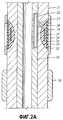
Фиг.2А показывает поперечное сечение обычного воротника 21 бура, оснащенного для измерения удельного сопротивления распространения. Воротник 21 включает углубление 29, образованное по окружности вокруг внешней области воротника на некоторой заданной глубине. Датчик 25 удельного сопротивления распространения расположен в углублении 29. Воротник 21 оснащен внутренним рукавом или шасси 26, расположенным на нем, чтобы образовывать полость для размещения электронного модуля 22. Модуль 22 присоединен к датчику 25 через электрическое соединение 27, пересекающее перемычку 28 внутри стенки воротника 21 бура. Датчик 25 герметизирован в углублении 29 (например, при помощи стекловолоконного заполнителя 20) и покрыт сверху резиновой формовкой 19. Защитное устройство 23 прикреплено на верху формовки 19 над углублением 29 для защиты датчика 25 от повреждений во время процесса бурения. Воротник 21 может также быть снабжен сменной лентой 38 дополнительно к защите датчика. Как показано на фиг.2В, защитное устройство 23 включает множество продольных щелей 24, заполненных изолирующим материалом, известным из уровня техники.Fig. 2A shows a cross section of a
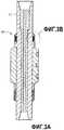
Датчик бокового удельного сопротивления (т.е. тороидальная антенна) индуцирует магнитное поле в пласте. Фиг.3А показывает стандартный датчик бокового сопротивления, который описан в Bonner et al. «A New Generation of Electrode Resistivity Measurements for Formation Evaluation While Drilling», SPWLA, 35th Annual Logging Symposium, June 19-22, 1994, Paper 00, и патенте США №5339037, выданном Bonner et al. Показан воротник 31 LWD. Датчик бокового удельного сопротивления сконструирован как рукав 30, который предусмотрен на воротнике 31 бура и закреплен на месте.A lateral resistivity sensor (i.e., a toroidal antenna) induces a magnetic field in the formation. 3A shows a standard side drag sensor as described in Bonner et al. «A New Generation of Electrode Resistivity Measurements for Formation Evaluation While Drilling», SPWLA, 35th Annual Logging Symposium, June 19-22, 1994, Paper 00 and U.S. Patent №5339037, issued to Bonner et al.
Фиг.3В показывает увеличенный участок бокового датчика 30, описанного в патенте Bonner et. al. Как показано, тороидальная антенна 35, включающая проводящий провод 33, намотанный вокруг сердечника, встроена в изолирующий материал 36 и защищена металлическим защитным устройством 37. Чтобы позволить поперечному магнитному полю быть индуцированным в пласт, защитное устройство для бокового датчика не должно замыкать цепь тока. Только один конец, верхний конец, проводящего защитного устройства 37 контактирует с воротником 31 бура. Патент США №340856, выданный Redwin et al. описывает тороидальные антенны, имеющие металлические защитные внешние стенки. Предложенные тороидальные антенны сконструированы в металлических цилиндрах, которые обеспечены над воротником и привинчены в воротник бура.3B shows an enlarged portion of the
Существует необходимость скважинных инструментов, которые обеспечивают объединенное измерение удельного сопротивления, используя оба типа датчиков удельного сопротивления - боковой тип и электродинамический тип/тип распространения. Также предпочтительно, что такие инструменты имеют источники/датчики, встроенные прямо в инструмент.There is a need for downhole tools that provide combined resistivity measurements using both types of resistivity sensors — side type and electrodynamic type / propagation type. It is also preferred that such tools have sources / sensors built directly into the tool.
Сущность изобретенияSUMMARY OF THE INVENTION
Изобретение обеспечивает компоновку удлиненной трубы, имеющей продольную ось и выполненную с возможностью подземного размещения, содержащую: углубление на внешней стенки трубы, проходящее по окружной поверхности вокруг продольной оси трубы, изолирующий базовый слой, расположенный в углублении;The invention provides an arrangement of an elongated pipe having a longitudinal axis and configured for underground placement, comprising: a recess on the outer wall of the pipe extending along a circumferential surface around the longitudinal axis of the pipe, an insulating base layer located in the recess;
тороидальную антенну, расположенную над изолирующим базовым слоем, иa toroidal antenna located above the insulating base layer, and
защитное устройство, расположенное над углублением и выполненное с возможностью предотвращения протекания электрического тока вдоль защитного устройства в направлении, параллельном продольной оси трубы вблизи тороидальной антенны, при этом указанная компоновка удлиненной трубы представляет собой воротник бура или каротажный инструмент удельного сопротивления.a protective device located above the recess and configured to prevent electric current from flowing along the protective device in a direction parallel to the longitudinal axis of the pipe near the toroidal antenna, wherein said elongated pipe arrangement is a drill collar or resistivity logging tool.
При этом компоновка удлиненной трубы дополнительно содержит изолирующий наполнитель, расположенный в остающемся участке углубления, механизм компенсации давления, расположенный рядом с тороидальной антенной. При этом тороидальная антенна содержит проводящий провод, расположенный над изолирующим базовым слоем.The layout of the elongated pipe further comprises an insulating filler located in the remaining portion of the recess, a pressure compensation mechanism located next to the toroidal antenna. In this case, the toroidal antenna contains a conductive wire located above the insulating base layer.
Кроме того, тороидальная антенна содержит тороидальную сердцевину, сформированную из одного из материалов: магнитно-проницаемого материала, намотанного вокруг изолирующего базового слоя, из ферритового материала, расположенного в углублении.In addition, the toroidal antenna contains a toroidal core formed of one of the materials: a magnetically permeable material wound around an insulating base layer, of ferrite material located in the recess.
В компоновке удлиненной трубы защитное устройство содержит изолирующий механизм для предотвращения протекания электрического тока вдоль защитного устройства в направлении, параллельном продольной оси трубы, а изолирующий механизм содержит круговую щель, заполненную изолирующим материалом.In the arrangement of the elongated pipe, the protective device includes an insulating mechanism to prevent electric current from flowing along the protective device in a direction parallel to the longitudinal axis of the pipe, and the insulating mechanism contains a circular slit filled with insulating material.
Кроме того, компоновка удлиненной трубы дополнительно содержит электрически изолированный материал, расположенный между соединением, сформированным между защитным устройством и трубой.In addition, the arrangement of the elongated pipe further comprises an electrically insulated material located between the connection formed between the protective device and the pipe.
Компоновка удлиненной трубы согласно первому аспекту изобретения представляет собой каротажный инструмент удельного сопротивления или воротник бура.The arrangement of the elongated pipe according to the first aspect of the invention is a resistivity logging tool or drill collar.
При этом когда компоновка удлиненной трубы представляет собой каротажный инструмент удельного сопротивления, она содержит:Moreover, when the layout of the elongated pipe is a resistivity logging tool, it contains:
удлиненную первую проводящую трубу, имеющую центральное отверстие и изолированное круговое отверстие вдоль ее стенки для предотвращения протекания тока через отверстие;an elongated first conductive pipe having a central hole and an insulated circular hole along its wall to prevent current from flowing through the hole;
удлиненную вторую проводящую трубу, имеющую датчик бокового удельного сопротивления, установленный на ней;an elongated second conductive pipe having a lateral resistivity sensor mounted on it;
причем вторая труба расположена внутри первой трубы таким образом, что датчик бокового удельного сопротивления был размещен вблизи изолированного кругового отверстия на первой трубе, иmoreover, the second pipe is located inside the first pipe so that the lateral resistivity sensor was placed near an insulated circular hole on the first pipe, and
причем путь тока формируется между первой и второй трубой на любой стороне изолированного кругового отверстия, когда вторая труба расположена внутри первой трубы.wherein a current path is formed between the first and second pipe on either side of the insulated circular hole when the second pipe is located inside the first pipe.
При этом между внешней поверхностью второй трубы и внутренней поверхностью первой трубы сформировано проводящее соединение на любой стороне изолированного кругового отверстия, когда вторая труба расположена внутри первой трубы, при этом проводящее соединение сформировано посредством непосредственного контактирования между трубами или посредством проводящего элемента, расположенного между трубами.In this case, a conductive connection is formed on either side of the insulated circular hole between the outer surface of the second pipe and the inner surface of the first pipe, when the second pipe is located inside the first pipe, while the conductive connection is formed by direct contact between the pipes or by means of a conductive element located between the pipes.
Согласно второму аспекту изобретения предусмотрен способ размещения датчика бокового удельного сопротивления на участок компоновки трубы, имеющей продольную ось и выполненную с возможностью подземного размещения, содержащий этапы, при которых:According to a second aspect of the invention, there is provided a method for placing a lateral resistivity sensor on a pipe assembly portion having a longitudinal axis and configured for underground placement, comprising the steps of:
создают углубление во внешней стенке участка трубы;create a recess in the outer wall of the pipe section;
формируют базовый слой изолирующего материала в углублении;forming a base layer of insulating material in the recess;
формируют тороидальную сердцевину посредством намотки магнитно-проницаемого материала над базовым слоем;form a toroidal core by winding magnetically permeable material over the base layer;
наматывают проводящий провод вокруг тороидальной сердцевины для формирования тороидальной антенны иwinding a conductive wire around the toroidal core to form a toroidal antenna and
устанавливают защитное устройство над углублением, при этом защитное устройство выполнено с возможностью предотвращения протекания электрического тока в защитном устройстве в направлении, параллельном продольной оси трубы вблизи тороидальной антенны.a protective device is mounted above the recess, while the protective device is configured to prevent electric current from flowing in the protective device in a direction parallel to the longitudinal axis of the pipe near the toroidal antenna.
Кроме того, способ дополнительно содержит этап заполнения оставшегося участка углубления изолирующим наполнителем, подгонку механизма компенсации давления в углублении.In addition, the method further comprises the step of filling the remaining portion of the recess with an insulating filler, adjusting the pressure compensation mechanism in the recess.
Кроме того, согласно способу размещают бобину на базовый слой до формирования тороидальной сердцевины, причем бобина имеет желоб для направления наматывания магнитно-проницаемого материала, а также размещают изолирующий материал над тороидальной сердцевиной в щели бобины.In addition, according to the method, the bobbin is placed on the base layer until a toroidal core is formed, the bobbin having a groove for guiding the winding of the magnetically permeable material, and also insulating material is placed above the toroidal core in the slit of the bobbin.
Кроме того, согласно второму аспекту изобретения защитное устройство содержит изолирующий механизм для предотвращения протекания электрического тока вдоль защитного устройства в направлении, параллельном продольной оси трубы вблизи тороидальной антенны, при этом изолирующий механизм содержит круговую щель, заполненную изолирующим материалом, в защитном устройстве.In addition, according to a second aspect of the invention, the protective device comprises an insulating mechanism for preventing electric current from flowing along the protective device in a direction parallel to the longitudinal axis of the pipe near the toroidal antenna, while the insulating mechanism comprises a circular slit filled with insulating material in the protective device.
Кроме того, согласно способу размещают электрически изолирующий материал между соединением, сформированным между защитным устройством и трубой.In addition, according to the method, an electrically insulating material is placed between a joint formed between the protective device and the pipe.
Другие аспекты и преимущества изобретения станут очевидными из следующего описания и приложенной формулы изобретения.Other aspects and advantages of the invention will become apparent from the following description and the appended claims.
Краткое описание чертежейBrief Description of the Drawings
Фиг.1А показывает традиционную систему LWD со скважинным инструментом, расположенным в скважине.1A shows a conventional LWD system with a downhole tool located in a well.
Фиг.1В показывает традиционный каротажный инструмент для измерения бокового удельного сопротивления.1B shows a conventional logging tool for measuring lateral resistivity.
Фиг.2А показывает поперечное сечение традиционного каротажного инструмента для измерения удельного сопротивления распространения.2A shows a cross section of a conventional logging tool for measuring resistivity.
Фиг.2В представляет схему внешней области инструмента фиг.2А.Fig. 2B is a diagram of the outer region of the tool of Fig. 2A.
Фиг.3А показывает традиционный каротажный инструмент для измерения удельного сопротивления, имеющий размещенный на рукаве датчик бокового удельного сопротивления.3A shows a conventional resistivity logging tool having a lateral resistivity sensor located on a sleeve.
Фиг.3В - детальный вид датчика бокового удельного сопротивления инструмента согласно фиг.3А.Fig. 3B is a detailed view of the tool lateral resistivity sensor of Fig. 3A.
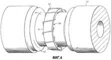
Фиг.4 - схема тороидальной антенны, расположенной на трубе согласно изобретению.4 is a diagram of a toroidal antenna located on a pipe according to the invention.
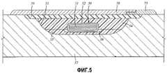
Фиг.5 показывает поперечное сечение тороидальной антенны, смонтированное в углублении на трубе согласно изобретению.5 shows a cross section of a toroidal antenna mounted in a recess on a pipe according to the invention.
Фиг.6 показывает поперечное сечение тороидальной антенны, имеющее бобину как направляющее устройство в углубление трубы согласно изобретению.6 shows a cross section of a toroidal antenna having a bobbin as a guiding device in a recess of a pipe according to the invention.
Фиг.7А показывает защитное устройство для бокового датчика согласно изобретению.7A shows a protective device for a side sensor according to the invention.
Фиг.7В показывает защитное устройство для датчика удельного сопротивления согласно изобретению.7B shows a protective device for a resistivity sensor according to the invention.
Фиг.8 иллюстрирует поперечное сечение защитного устройства, расположенного на трубе согласно изобретению.Fig. 8 illustrates a cross-section of a protective device located on a pipe according to the invention.
Фиг.9 - иллюстрирует поперечное сечение бокового датчика с механизмом компенсации давления согласно изобретению.Fig. 9 illustrates a cross section of a side sensor with a pressure compensation mechanism according to the invention.
Фиг.10 представляет схему трубы с изолирующим разрывом или зазором согласно изобретению.Figure 10 is a diagram of a pipe with an insulating gap or gap according to the invention.
Фиг.11 показывает объединенные боковой датчик и датчик распространения, расположенные на трубе и защищаемые встроенным защитным устройством согласно изобретению.11 shows a combined side sensor and a distribution sensor located on a pipe and protected by an integrated safety device according to the invention.
Фиг.12А показывает инструмент и LWD для отображения измерений удельного сопротивления, объединенный с боковым датчиком, расположенным в углублении воротника бура согласно изобретению.12A shows a tool and LWD for displaying resistivity measurements combined with a side sensor located in a recess of a drill collar according to the invention.
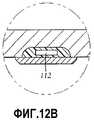
Фиг.12В-D представлены детальные виды датчиков, показанных на фиг.12А.12B-D are detailed views of the sensors shown in FIG. 12A.
Фиг.13 иллюстрирует блок-схему способа монтажа бокового датчика на трубе согласно изобретению.13 illustrates a flow diagram of a method of mounting a side sensor on a pipe according to the invention.
Фиг.14 иллюстрирует блок-схему способа для монтирования комбинации бокового датчика и датчика распространения на трубе согласно изобретению.14 illustrates a flow diagram of a method for mounting a combination of a side sensor and a propagation sensor on a pipe according to the invention.
Подробное описаниеDetailed description
Варианты осуществления настоящего изобретения относятся к способам и устройству для измерения электромагнитных свойств подземных пластов, проходящих через скважину. Варианты осуществления изобретения включают инструменты, выполненные с возможностью определения удельных сопротивлений в одной и той же области пласта, используя оба электромагнитных датчика - боковой датчик и датчик индуцирования или распространения. Некоторые варианты осуществления изобретения относятся к способам изготовления или сборки таких инструментов. Согласно вариантам осуществления изобретения датчики бокового типа и датчики распространения совместно реализуются в трубе для подземного использования. Объединенная реализация бокового датчика и датчика распространения на одной трубе (компоновка трубы) делает возможным, если требуется, использование встроенной в трубу сборки защитного устройства датчиков. Более важно, реализация объединенных бокового датчика и датчика распространения делает возможным получение многомодовых измерений удельного сопротивления из одной и той же подземной области за один спуск-подъем, таким образом обеспечивая более точное и надежное определение подземного удельного сопротивления.Embodiments of the present invention relate to methods and apparatus for measuring the electromagnetic properties of subterranean formations passing through a well. Embodiments of the invention include tools configured to determine resistivities in the same area of the formation using both electromagnetic sensors — a side sensor and an induction or propagation sensor. Some embodiments of the invention relate to methods for manufacturing or assembling such tools. According to embodiments of the invention, the side type sensors and the distribution sensors are jointly implemented in a pipe for underground use. The combined implementation of the lateral sensor and the propagation sensor on one pipe (pipe layout) makes it possible, if required, to use the sensor protection device assembly built into the pipe. More importantly, the implementation of the combined lateral and propagation sensors makes it possible to obtain multimode resistivity measurements from the same underground region in a single descent, thereby providing a more accurate and reliable determination of the underground resistivity.
Согласно вариантам осуществления изобретения тороидальный датчик для инструмента бокового сопротивления монтируется в скважинной трубе. Как указывалось выше, тороидальные передатчики или приемники традиционных инструментов для измерения бокового удельного сопротивления обычно монтируются на рукаве, который предусмотрен на трубе. На такой выбор конструкции влияют такие факторы, как, например, давление физической силы на воротник бура с полостями, сложности конструкции и упрощение технического обслуживания или замены. Исследование напряжений, осуществляемое настоящими изобретателями, показало, что воротник бура, имеющий углубления, вырезанные на его внешней стенке, такого размера и формы, требуемых для удержания тороидальных датчиков, не ослабит значительно трубу.According to embodiments of the invention, a toroidal sensor for a side drag tool is mounted in the downhole pipe. As mentioned above, toroidal transmitters or receivers of traditional tools for measuring lateral resistivity are usually mounted on the sleeve, which is provided on the pipe. Such a design choice is influenced by factors such as, for example, the pressure of physical force on the drill collar with cavities, the complexity of the design and the simplification of maintenance or replacement. The stress study carried out by the present inventors showed that the drill collar having recesses cut on its outer wall, of the size and shape required to hold the toroidal sensors, will not significantly weaken the pipe.
Фиг.4 иллюстрирует датчик бокового удельного сопротивления (тороидальную антенну), смонтированную в углублении трубы согласно варианту осуществления изобретения. Фиг.5 показывает участок продольного сечения тороидального датчика. Как показано на фиг.4 и 5, труба 57 включает углубление 53. Основа углубления 53 вырезается на некоторую требуемую глубину. Боковой датчик, состоящий из тороидальной антенны 50, которая состоит из магнитного сердечника 51 и проводящего провода 52, смонтирована в углублении 53.4 illustrates a lateral resistivity sensor (toroidal antenna) mounted in a recess of a pipe according to an embodiment of the invention. Figure 5 shows a section of a longitudinal section of a toroidal sensor. As shown in FIGS. 4 and 5, the
Согласно одному варианту осуществления изобретения на месте углубления 53 может быть смонтирована тороидальная антенна 50. Тороидальная антенна 50 может быть смонтирована на месте посредством размещения изолирующего материала в основе углубления 53 для формирования базового слоя 55. Изолирующий базовый слой 55 может включать бороздки 56 для обеспечения каналов для проводящего провода 52, намотанного вокруг магнитного тороидального сердечника 51 в форме обруча в углублении 53.According to one embodiment of the invention, a
Магнитный сердечник 51 смонтирован на базовом слое 55 в углублении 53. Одним способом является монтирование магнитного сердечника 51, на месте в углублении обматывая ленту, выполненную из ферромагнитного материала. Альтернативно магнитный сердечник может быть скомпонован в углублении из кусочков, выполненных из ферромагнитного материала (например, ферритов). Сердечник 51 может быть также скомпонован из кусочков и пропитан эпоксидной смолой для удержания структуры (не показано). Примером подходящей ферромагнитной ленты является лента SUPERMALLOY™, которая, например, может иметь размеры 1 дюйм (2,54 см) в ширину и 0,002 дюйма (0,05 см) в толщину. SUPERMALLOY™ является высокоочищенной и специально обработанной 80% железоникелевым сплавом для использования в сердечнике, обмотанном лентой, и может быть приобретена от коммерческих предприятий, таких как Magnetic Metals Company (Anaheim, Ca). SUPERMALLOY™ производится, чтобы иметь высокую начальную магнитную проницаемость и низкие потери. Для некоторых приложений может не требоваться магнитный сердечник с высокой магнитной проницаемостью. Может быть достаточно сердечника с относительной магнитной проницаемостью, равной 1. Магнитная лента обматывается по окружности вокруг изолирующего базового слоя 55 для формирования магнитно-проницаемого тороидального сердечника 51. Обмотка продолжается, пока не будет достигнута требуемая толщина (например, 0,10 дюймов [0,254 см] - 0,15 дюймов [0,381 см]) магнитного сердечника 51. Чтобы завершить изготовление тороидальной антенны 50, затем вокруг сердечника 51 наматывается проводящий провод 52. Процесс намотки, например, завершается пропусканием проводящего провода 52 через канавку (и) 56, образованную в изолирующем базовом слое 55. Датчик бокового удельного сопротивления может также быть реализован другими способами, такими как при проскальзывании датчика в суженную область трубы или корпуса (не показано).The
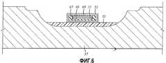
Фиг.5 также показывает, что, как только завершена установка тороидальной антенны 50, оставшаяся зона в углублении 53 может быть заполнена изолирующим материалом 54, который фиксирует тороидальную антенну 50 в углублении 53. Примеры подходящих изолирующих материалов включают эпоксидную смолу и стекловолокно. Дополнительно слой эластомера (например, резины) может быть сформирован поверх изолирующего материала, чтобы герметизировать углубление 53 и его содержимое от скважинных флюидов при размещении датчика в скважине. Примеры эластомеров могут включать натуральный и синтетический каучук и синтетические эластомеры. Примером подходящего эластомера является фторэластомер, продаваемый DuPont Dow Elastomers под торговой маркой VITON™ (Уилмингтон, Делавэр). Резина или слой эластомера 59 герметизирует сборку датчика, промывая поверхность трубы 57. Наконец, углубление 53 и его содержимое покрываются защитным устройством 58, которое защищает датчик от среды, окружающий скважину. Защитное устройство 58 включает изолирующий механизм 75 (описанный подробно ниже) для предотвращения протекания тока вдоль защитного устройства 58 в продольном направлении.Figure 5 also shows that, once the installation of the
Фиг.6 показывает другой вариант осуществления изобретения. Тороидальная антенна расположена внутри трубы, включающей бобину 67, помещенную над изолирующим базовым слоем 55 до того, как была намотана магнитная лента. Бобина 67 выполнена из изолирующего материала и может содержать два или более кусочков, которые могут быть скомпонованы в углублении. Бобина может включать вырез (желоб) 68, который направляет магнитную ленту во время обмотки и удерживает тороидальный сердечник 51. Для бобины 67 может быть использован любой подходящий материал или композит, включая коммерчески доступные материалы, такие как RANDOLITE™, PEEK™, KEVLAR™, стекловолокно или основанные на полиарилэфиркетоне термопластические материалы, как описано в патентах США №6084052 и 6300762. Вырез 68 бобины 67 должен быть немного шире, чем ширина магнитной ленты. Если используется бобина 67, то бороздка(и) (56 на фиг.5), используемая для упрощения намотки проводящего провода 52, может быть включена в бобину 67 вместо изолирующего базового слоя 55. Как только сконфигурирован тороидальный сердечник 51, вершина желоба 68 бобины 67 может быть закрыта лентой 69, выполненной из изолирующего материала, такого как стеклоткань, для закрепления тороидальной сердцевины 51 в вырезе 68 бобины 67. Защитное устройство 58, изолирующий механизм 75 и т.д. (показанные на фиг.5) также объединены в варианте осуществления на фиг.6, но они не показаны для ясности иллюстрации. Другие варианты осуществления изобретения могут быть сконфигурированы без магнитного сердечника 51 (не показано), особенно подходящего для высокочастотных приложений. Такие варианты осуществления требуют расположения проводящего провода 52 над изолирующим базовым слоем 55, образовывая «воздушную сердцевину». Кроме того, другие варианты осуществления могут быть сконфигурированы с проводящим проводом, намотанным на бобину 67 без магнитной сердцевины 51 (не показано).6 shows another embodiment of the invention. A toroidal antenna is located inside the tube, including the
Возвращаясь к фиг.5, защитное устройство 58 предпочтительно сконструировано из прочного материала, такого как металл. Важность правильно сконфигурированного защитного устройства известна из уровня техники. Например, патент США №6566881, выданный Omeragie et al., раскрывает различные защитные устройства для электромагнитных каротажных инструментов, включая инструменты, имеющие поперечные антенны.Returning to FIG. 5, the
Тем не менее, конструкция защитного устройства для соленоидальной антенны, которая формирует магнитные диполи, отличается от конструкции защитных устройств для тороидальной антенны, которая формирует электрические диполи и функционирует на значительно меньших частотах. Из уровня техники хорошо известно, что эффективное функционирование антенны и конструкция защитного устройства зависят от рабочих частот и физических характеристик антенны. Как указывалось выше, антенна индуцирования и распространения выполнена с возможностью формирования высокочастотного электрического поля в пласте, тогда как тороидальная антенна конструируется для формирования низкочастотного магнитного поля в пласте. Следовательно, традиционные защитные устройства, конструируемые для антенн индуцирования и распространения, обычно не подходят для использования в тороидальных антеннах.However, the design of the protective device for the solenoidal antenna, which forms the magnetic dipoles, is different from the design of the protective devices for the toroidal antenna, which forms the electric dipoles and operates at much lower frequencies. It is well known in the art that the effective functioning of the antenna and the design of the protective device depend on the operating frequencies and physical characteristics of the antenna. As indicated above, the induction and propagation antenna is configured to generate a high-frequency electric field in the formation, while a toroidal antenna is designed to form a low-frequency magnetic field in the formation. Therefore, traditional protective devices designed for induction and propagation antennas are generally not suitable for use in toroidal antennas.
Покрытие тороидальной антенны традиционным защитным устройством антенны приведет к короткому замыканию электрического тока, индуцируемого тороидальной антенной. Вместо протекания тока через скважину и пласт ток сначала течет в защитное устройство. Сигнал пласта будет уменьшен ниже уровня, соответствующего для измерения удельного сопротивления. Подходящее металлическое защитное устройство для тороидальной антенны включает круговую щель или кольцо, чтобы обеспечить электрическую изоляцию между защитным устройством и нижележащей проводящей опорой. Фиг.7А показывает защитное устройство 58 изобретения с изолирующей щелью 75. Эта щель 75 состоит из изолирующего материала (например, стекловолокна, керамики, RANDOLITE™). Она может быть расположена в любом месте вдоль защитного устройства, но обычно проще выполнить изолирующую щель 75 на одном из концов защитного устройства. Специалисты в данной области техники могут выбрать технологию из многих известных из уровня техники для формирования щели. Изолирующий материал может представлять отдельный кусок, прикрепленный в место или монтированный на защитном устройстве (например, отформированный эластомер или композитный изолирующий материал) как встроенная часть. В некоторых вариантах осуществления изолирующий материал может располагаться и удерживаться защитным устройством (не показано).Coating the toroidal antenna with a traditional antenna protector will short-circuit the electric current induced by the toroidal antenna. Instead of flowing current through the well and formation, the current first flows into the protective device. The formation signal will be reduced below the level appropriate for resistivity measurements. A suitable metal protective device for the toroidal antenna includes a circular slot or ring to provide electrical insulation between the protective device and the underlying conductive support. Fig. 7A shows a
Альтернативой включению в защитное устройство щели являются использование цельного, цельнометаллического защитного устройства и его монтаж таким образом, чтобы оно электрически связывало проводящую часть трубы над тороидом с проводящей частью трубы под тороидом. Способ такого выполнения показан на фиг.8. Как показано на фиг.8, кольцо 80 изолирующего материала 80 включено в трубу 57 таким образом, чтобы один конец защитного устройства 58 был изолирован кольцом от непосредственного контактирования с трубой.An alternative to incorporating a gap in the protective device is to use an integral, all-metal protective device and install it in such a way that it electrically connects the conductive part of the pipe above the toroid with the conductive part of the pipe under the toroid. A method for this is shown in FIG. As shown in FIG. 8, a
Фиг.7А и 8 являются примерами круговых щелей или колец с изолирующим материалом для предотвращения протекания тока вдоль защитного устройства в продольном направлении над тороидальной антенной 50. Специалисты в данной области техники оценят, что могут быть использованы другие типы круговых щелей или колец для осуществления изобретения. Некоторые варианты осуществления изобретения могут включать сегментные металлические защитные устройства для обеспечения необходимой изоляции (не показано).7A and 8 are examples of circular slots or rings with insulating material to prevent current flowing along the protective device in the longitudinal direction above the
Специалист в данной области техники примет к сведению, что, когда труба расположена в скважине, заполненной буровым раствором, на тороидальную антенну (50 на фиг.4) будет действовать гидростатическое давление в 20000 фунтов на квадратный дюйм (1,406 кг/см2). Это давление будет действовать на тороидальную антенну 50 изнутри и может вызвать деформации антенны, уменьшая магнитную проницаемость ее сердцевины 51 и уменьшая ее индуктивность и эффективность.One of ordinary skill in the art will recognize that when the pipe is located in a well filled with drilling fluid, a toroidal antenna (50 in FIG. 4) will be affected by a hydrostatic pressure of 20,000 psi (1,406 kg / cm2 ). This pressure will act on the
Для минимизирования неблагоприятных влияний гидростатического давления тороидальные антенны согласно изобретению могут быть реализованы посредством включения механизма компенсации давления. Например, компенсация давления может быть получена заменой некоторых или всех изолирующих материалов (например, 54 на фиг.5), которые удерживают тороидальную антенну в углублении (53 на фиг.5) на мягкий эластомер или резину. Фиг.9 иллюстрирует вариант осуществления тороидального датчика согласно изобретению, который включает механизм компенсации давления, конструкция которого подобна показанной на фиг.6. Одно отличие заключается в том, что в стенке 57 трубы установлен порт 90. Другое отличие в том, что заполняющий материал 54 является подходящим пористым и проницаемым материалом, таким как непропитанная стекловолоконная ткань. После того как резина 59 сформирована в местоположении, углубление 53 освобождается через порт 90 и снова заполняется маслом при атмосферном давлении. Затем порт 90 герметизируется пробкой 91. Резиновая прокладка 59 действует как сильфоны для уравновешивания давления на тороидальном сердечнике 51 с давлением вне трубы.In order to minimize the adverse effects of hydrostatic pressure, the toroidal antennas of the invention can be implemented by incorporating a pressure compensation mechanism. For example, pressure compensation can be obtained by replacing some or all of the insulating materials (for example, 54 in FIG. 5) that hold the toroidal antenna in the recess (53 in FIG. 5) with a soft elastomer or rubber. Fig.9 illustrates an embodiment of a toroidal sensor according to the invention, which includes a pressure compensation mechanism, the design of which is similar to that shown in Fig.6. One difference is that
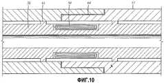
Фиг.10 показывает другой вариант осуществления изобретения. В этом варианте в проводящей внешней трубе 57 выполнено электрически изолированное отверстие или разрыв 60, а тороидальная антенна 50 смонтирована на проводящей внутренней трубе или шасси 26, расположенной на ней. Разрыв 60 образует разомкнутую цепь тока, протекающего вдоль трубы, предотвращая протекание тока через разрыв 60. С любой стороны разрыва 60 образовано проводящее соединение 61 между трубами для обеспечения пути тока между трубами. Фиг.10 иллюстрирует вариант осуществления изобретения, в котором электрически соединенные соединения 61 между трубами реализованы посредством вытягивания наружной стороны шасси 26, обеспечивая прямой контакт с внутренней поверхностью внешней трубы 57. Может быть использовано другое подходящее средство для обеспечения пути тока между трубами, как известно из уровня техники. Например, между трубами может быть установлена волновая пружина для обеспечения проводящего элемента (не показано). Электронный модуль для антенны 50 может быть расположен в трубах, как описано здесь или используя другое средство, известное из уровня техники.10 shows another embodiment of the invention. In this embodiment, an electrically insulated hole or
При работе тороидальная антенна 50 формирует токовый контур, в котором ток течет через шасси 26 и внешнюю трубу 57, возвращаясь к внешней трубе через пласт. Таким образом, варианты осуществления изобретения, включающие изолирующий разрыв 60, обычно включают более чем один разрыв, один для формирования разности напряжений через трубу и другой для осуществления измерения аксиального тока, используя другой тороид, функционирующий как приемник. Скважинные трубы, выполненные с изолирующими разрывами или щелями, известны в нефтяной промышленности, более точно, в области телеметрии. Патент США №6098727, выданный Ringgenberg et al., описывает скважинные трубки с изолирующими щелями. На внешнюю область внешней трубы также может быть помещено защитное устройство над изолирующим разрывом 60, чтобы защитить щель от среды и дополнительно изолировать разрыв от паразитных токов в скважине (не показано). Такое защитное устройство может быть сформировано из любого подходящего изолирующего материала и расположено на трубе, как известно из уровня техники.In operation, the
Такая конструкция предлагает несколько преимуществ: антенна механически защищена трубой; тороид не подвержен прямому давлению скважины, так что материал сердцевины сохраняет более высокую магнитную проницаемость и можно избежать подачи и прокладки электрических проводов через внешнюю трубу. Также имеет место преимущество над непосредственным управлением щелью, т.к. не требуется, чтобы шасси 26 было изолировано от трубы 57, что может быть трудным в некоторых зонах, таких как вокруг зон герметизации между шасси и трубой.This design offers several advantages: the antenna is mechanically protected by the pipe; the toroid is not subject to direct well pressure, so that the core material maintains a higher magnetic permeability and the supply and routing of electrical wires through the outer pipe can be avoided. There is also an advantage over direct slot control, as the
Боковая антенна, расположенная в трубе, имеет схожие характеристики с характеристиками антенны индуцирования. С этими различными типами датчиков, объединенными в одной трубе, инструмент может быть использован для измерения удельного сопротивления одной и той же подземной области, используя две различные технологии обнаружения. Дополнительно становится возможным устанавливать встроенное защитное устройство датчика для защиты датчиков. Заметим, что наряду с тем, что в некоторых случаях необходимо иметь встроенное защитное устройство, для индивидуальных датчиков могут быть использованы отдельные защитные устройства.The side antenna located in the pipe has similar characteristics to those of the induction antenna. With these different types of sensors combined in one pipe, the instrument can be used to measure the resistivity of the same underground area using two different detection technologies. Additionally, it becomes possible to install an integrated sensor protection device to protect the sensors. Note that, in addition to the fact that in some cases it is necessary to have a built-in protective device, separate protective devices can be used for individual sensors.
Фиг.11 показывает другой вариант осуществления изобретения. Представленный вид является поперечным сечением части трубы, имеющей датчик 104 бокового удельного сопротивления, сформированный в первом углублении 53, вырезанном в стенке трубы, и датчик 105 удельного сопротивления распространения, сформированный во втором углублении 103, вырезанном в стенке трубы. Электрические соединители 27, пересекающие перемычку 28 в стенке 57 трубы, электрически соединяют датчик 104 бокового удельного сопротивления и датчик 105 распространения с электронным модулем 102, помещенным в камеру, образованную шасси 26. Уплотнительные кольца или другое средство герметизации, известные из области техники, используются, чтобы гарантировать, что модуль 102 не подвергается действию подземных флюидов.11 shows another embodiment of the invention. The presented view is a cross section of a portion of a pipe having a
Фиг.11 также показывает встроенную антенну распространения и защитное устройство 108 тороидальной антенны, прикрепленное по окружности вокруг внешней стенки трубы. Встроенное защитное устройство 108 может быть в основном выполнено из металла и может быть сболчено, завинчено, приварено или закреплено на внешней поверхности трубы, используя любое подходящее средство, известное из уровня техники. В некоторых вариантах осуществления встроенное защитное устройство 108 может быть сконструировано из других износостойких неметаллических материалов, известных в технике. Тем не менее, металл является предпочтительным материалом в LWD приложениях благодаря его прочности и износостойкости. Встроенное защитное устройство 108 включает одну или более продольных щелей 24 над вторым углублением и датчиком 105 распространения. В этом варианте осуществления изолирующая щель 75 для защитного устройства 108 сформирована в стенке трубы рядом с боковым датчиком 104, используя любой подходящий изолирующий материал, известный из уровня техники. Другие варианты осуществления могут быть реализованы с датчиком 104 бокового удельного сопротивления и датчиком 105 удельного сопротивления распространения, расположенными в одном и том же углублении (не показано). Такой вариант осуществления может быть реализован, вытягивая углубление для размещения обоих датчиков и используя встроенное защитное устройство 108.11 also shows a built-in propagation antenna and a
Как указано выше и показано на фиг.8, защитное устройство тороидальной антенны может быть цельнометаллическим модулем, обеспечивающим сборку защитного устройства/трубы, приспособленного для предотвращения течения тока вдоль защитного устройства через тороид. На фиг.11 конструкция изолирующей щели или кольца 75 и защитного устройства гарантирует, что вблизи с датчиком 104 бокового удельного сопротивления предотвращается течение тока вдоль защитного устройства. Альтернативно круговая щель может быть выполнена в самом защитном устройстве, как показано на фиг.7А.As indicated above and shown in FIG. 8, the protective device of the toroidal antenna can be an all-metal module that provides the assembly of the protective device / pipe adapted to prevent current flowing along the protective device through the toroid. 11, the design of the insulating gap or
Как обсуждалось выше, обычные антенны распространения индуцируют электрические поля, которые вызывают течение электрических токов по окружности опоры трубы в скважине и пласте. Следовательно, антенны распространения обычно используют защитные устройства, имеющие продольные щели, чтобы предотвратить индуцирование поперечных (азимутальных) токов в защитном устройстве вместо пласта. Фиг.7В показывает один пример защитного устройства 58' с щелями 76, заполненными изолирующим материалом, который может быть использован для защиты антенны распространения согласно изобретению.As discussed above, conventional propagation antennas induce electric fields that cause electric currents to flow around the circumference of the pipe support in the borehole and formation. Therefore, propagation antennas typically use protective devices having longitudinal slots to prevent the induction of transverse (azimuthal) currents in the protective device instead of the formation. Fig. 7B shows one example of a
Такие защитные устройства дополнительно описаны в патенте США №4968940. Следует отметить, что, хотя показаны несколько щелей 76, варианты осуществления изобретения не ограничиваются любым конкретным числом или формой щелей. Другие варианты осуществления также могут быть реализованы с сегментными защитными устройствами (не показано).Such protective devices are further described in US Pat. No. 4,968,940. It should be noted that although
Варианты осуществления изобретения, проиллюстрированные выше, могут иметь любое число наборов датчиков распространения или боковых наборов датчиков, расположенных вдоль оси трубы. Дополнительно может быть выбрано любое размещение набора в зависимости от конкретной глубины исследования или требуемой вертикальной разрешающей способности.Embodiments of the invention illustrated above may have any number of sets of distribution sensors or side sets of sensors located along the axis of the pipe. Additionally, any placement of the kit can be selected depending on the specific depth of the study or the required vertical resolution.
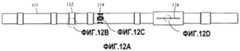
Способы согласно изобретению позволяют сформировать тороидальную антенну в углублении трубы, приспособленную к подземному использованию. Приложения этих способов не ограничиваются инструментами для измерения удельного сопротивления, описанными здесь. Например, инструменты или устройство, которые в настоящее время используют тороидальные антенны, расположенные на рукаве и прикрепленные к нему, могут извлечь преимущества из наличия антенны, построенной в углублении или полости. Фиг.12 показывает другой вариант осуществления изобретения. Фиг.12А показывает вариант реализации инструмента GeoVision для измерения удельного сопротивления, производимый под торговой маркой GVR™ корпорации Schlumberger Technology (Хьюстон, Техас).The methods according to the invention allow the formation of a toroidal antenna in the recess of the pipe, adapted for underground use. Applications of these methods are not limited to the resistivity measurement tools described herein. For example, instruments or devices that currently use toroidal antennas located on a sleeve and attached to it can benefit from having an antenna built in a recess or cavity. 12 shows another embodiment of the invention. Fig. 12A shows an embodiment of a GeoVision resistivity measuring instrument manufactured under the trademark GVR ™ of Schlumberger Technology Corporation (Houston, TX).
Как показано на фиг.12А, тороидальная антенна 112 сформирована в углублении (как описано здесь) на участке воротника 111 бура. Фиг.12В показывает тороидальную антенну 112 более подробно. Инструмент также включает четыре больших дисковых электрода 114 для обеспечения азимутальных измерений удельного сопротивления (показано более подробно на фиг.12С). Инструмент дополнительно включает последовательность компактных дисковых электродов 116, расположенных на съемном стабилизаторе, для обеспечения измерений с высокой разрешающей способностью (показано более подробно на фиг.12D). Вариант GVR инструмента, показанный на фиг.12, может быть реализован в «гладкой» конструкции, без стабилизатора. В гладкой конфигурации устройство значительно меньше в диаметре по сравнению с настоящим GVR инструментом, потому что тороидальные антенны формируются в углублениях на стенке воротника в отличие от скольжения по воротнику бура. Гладким инструментом легче маневрировать в отклоненных или резко искривленных скважинах, и он имеет лучшую гидравлику.As shown in FIG. 12A, a
Варианты осуществления изобретения относятся к способу для размещения датчика бокового удельного сопротивления на участок удлиненной трубы, приспособленной для подземного размещения. Фиг.13 характеризует блок-схему способа. Сначала формируется углубление правильной глубины или вырезается на внешней стенке участка трубы (этап 121). Глубина должна быть достаточной, чтобы вместить сборку антенны, но не слишком глубокой в отношении излишнего ослабления трубы. Сначала может быть выполнено исследование напряжений, чтобы определить, достигаема ли требуемая глубина без чрезмерного ослабления трубы.Embodiments of the invention relate to a method for placing a lateral resistivity sensor on a portion of an elongated pipe adapted for underground placement. Fig.13 characterizes a block diagram of a method. First, a recess of the correct depth is formed or cut out on the outer wall of the pipe portion (step 121). The depth should be sufficient to accommodate the antenna assembly, but not too deep in relation to excessive weakening of the pipe. A stress study may be performed first to determine if the required depth is achieved without overly loosening the pipe.
Далее на основание углубления помещается (или покрывается) изолирующий материал для формирования изолирующего базового слоя между тороидальной антенной и проводящей трубой (этап 122). Могут быть использованы различные изолирующие материалы, известные из уровня техники, включая стекловолокно, PEEK™ и т.д. Толщина этого базового слоя изолирующего материала должна быть выбрана для обеспечения адекватной изоляции без избыточного нарастания. Например, слой в 0,04 дюйма (1,0 мм) стекловолокна может быть использован как базовый слой. Механизм компенсации давления, возможно, может быть построен на базовом слое для обеспечения опоры тороидальной антенны.Next, insulating material is placed (or covered) on the base of the recess to form an insulating base layer between the toroidal antenna and the conductive tube (step 122). Various insulating materials known in the art can be used, including fiberglass, PEEK ™, etc. The thickness of this base layer of insulating material must be selected to ensure adequate insulation without excessive build-up. For example, a 0.04 inch (1.0 mm) layer of fiberglass can be used as the base layer. The pressure compensation mechanism may possibly be built on the base layer to support the toroidal antenna.
Тороидальная сердцевина формируется в углублении базового слоя, используя магнитно-проницаемый материал, такой как лента SUPERMALLOY™ (этап 123). Лента соответствующего размера используется в зависимости от требуемых размеров тороидальной антенны. Например, может быть использован Permalloy, имеющий размеры одного дюйма (2,54 см) в ширину и 0,02 дюйма (1,0 см) в толщину, для обмотки сердцевины, имеющей толщину в диапазоне от 0,1 дюйма (0,254 мм) до 0,15 дюймов (0,381 мм). В некоторых вариантах осуществления может использоваться бобина, выполненная из изолирующего материала, для направления процесса наматывания ленты. Подходящая бобина, например, может быть выполнена из стекловолокна и иметь желоб или вырез (например, 1,05 дюймов (2,7 см) в ширину и 0,18 дюймов (0,5 см) в глубину), который может быть согласован с шириной ленты. При использовании бобины верхняя сторона бобины может быть покрыта изолирующим материалом (например, изолирующей лентой или стеклотканью), чтобы фиксировать тороидальную сердцевину в желобе бобины и изолировать намотку.A toroidal core is formed in the recess of the base layer using a magnetically permeable material such as SUPERMALLOY ™ tape (step 123). A tape of the appropriate size is used depending on the required size of the toroidal antenna. For example, Permalloy, having a size of one inch (2.54 cm) wide and 0.02 inch (1.0 cm) thick, can be used to wrap a core having a thickness in the range of 0.1 inch (0.254 mm) up to 0.15 inches (0.381 mm). In some embodiments, a bobbin made of an insulating material may be used to guide the tape winding process. A suitable bobbin, for example, can be made of fiberglass and have a groove or cut (for example, 1.05 inches (2.7 cm) wide and 0.18 inches (0.5 cm) deep), which can be matched to the width of the tape. When using a bobbin, the top side of the bobbin may be coated with insulating material (for example, insulating tape or fiberglass) to fix the toroidal core in the bobbin groove and insulate the winding.
Как только сформирована тороидальная сердцевина, покрытый проводящий провод наматывается или обматывается вокруг сердцевины, чтобы закончить антенну (этап 124). Подходящим проводящим проводом, например, является HMN провод с магнитным покрытием. Чтобы облегчить наматывание провода, на базовом слое или бобине могут быть вырезаны бороздки, чтобы обеспечить каналы для провода.Once a toroidal core is formed, the coated conductive wire is wound or wound around the core to complete the antenna (step 124). A suitable conductive wire, for example, is a magnetic coated HMN wire. To facilitate winding the wire, grooves can be cut out on the base layer or reel to provide channels for the wire.
Оставшееся пространство в углублении может быть затем заполнено изолирующим материалом. Подходящий изолирующий материал, например, может быть выбран из эпоксидной смолы, стекловолокна и т.д. Изолирующий наполнитель удержит тороидальную антенну на месте и также изолирует антенну от проводящего воротника бура. Слой резины или эластичного материала может быть также сформирован над верхней частью изолирующего материала и на трубе для герметизирования целой компоновки антенны от скважинных флюидов. На этапе 121 может быть обеспечено углубление с двухъярусным или ступенчатым профилем глубины (см., например, фиг.5, 6, 8), чтобы облегчить формовку слоя резины на одном уровне с поверхностью трубы. Подходящие эластичные материалы включают фтороэластомер, продаваемый DuPont Dow Elastomers под торговой маркой VITON™ (Уилмингтон, Делавэр). Относительно тонкий слой резины или эластика (например, 0,05 дюймов [1,3 мм] в толщину) обеспечивает надежную герметизацию.The remaining space in the recess may then be filled with insulating material. Suitable insulating material, for example, may be selected from epoxy resin, fiberglass, etc. An insulating filler holds the toroidal antenna in place and also isolates the antenna from the conductive drill collar. A layer of rubber or elastic material can also be formed above the top of the insulating material and on the pipe to seal the entire antenna assembly from the wellbore fluids. At
Наконец, над углублением может быть размещено защитное устройство, чтобы защитить компоновку тороидальной антенны (этап 125). Как отмечено выше, защитное устройство предпочтительно является металлическим. Компоновка защитного устройства приспособлена для предотвращения протекания электрического тока в зоне тороидальной антенны между участками трубы над и под антенной (т.е. в направлении, параллельном продольной оси трубы). Электрическая изоляция может быть обеспечена круговой щелью, заполненной изолирующим материалом, расположенной или на самом защитном устройстве, или на соединении между защитным устройством и трубой, как описано выше.Finally, a protective device may be placed above the recess to protect the arrangement of the toroidal antenna (step 125). As noted above, the protective device is preferably metallic. The arrangement of the protective device is adapted to prevent the flow of electric current in the area of the toroidal antenna between the pipe sections above and below the antenna (i.e., in a direction parallel to the longitudinal axis of the pipe). Electrical insulation can be provided by a circular gap filled with an insulating material located either on the protective device itself or on the connection between the protective device and the pipe, as described above.
Фиг.14 является блок-схемой, иллюстрирующей способ сборки инструмента для измерения удельного сопротивления, используя удлиненную трубу, приспособленную к подземному размещению согласно изобретению. Способ начинается с размещения датчика бокового удельного сопротивления в углублении в трубе, как описано здесь (этап 131). Антенна удельного сопротивления индуцирования и распространения также размещается на трубе, как описано здесь (этап 132). Антенны бокового удельного сопротивления могут быть сконфигурированы согласно раскрытым в описаниях технологиям. Антенны индуцирования/распространения и электроды могут быть сконфигурированы, используя известные из уровня техники способы. В предпочтительных вариантах осуществления бокового удельного сопротивления расположены в непосредственной близости к датчикам распространения, так чтобы они могли измерять в основном одни и те же вертикальные области пласта в одно и то же время. Другие варианты осуществления могут включать многочисленные наборы датчиков бокового удельного сопротивления и антенны удельного сопротивления индуцирования/распространения. Число и размещение этих наборов конфигурируется для обеспечения измерения на требуемой глубине исследования.14 is a flowchart illustrating a method of assembling a resistivity measuring tool using an elongated pipe adapted for underground placement according to the invention. The method begins by placing a lateral resistivity sensor in a recess in the pipe, as described here (step 131). An induction and propagation resistivity antenna is also placed on the pipe, as described here (step 132). Lateral resistivity antennas can be configured according to the techniques disclosed in the descriptions. Induction / propagation antennas and electrodes can be configured using methods known in the art. In preferred embodiments, the lateral resistivity is located in close proximity to the propagation sensors so that they can measure substantially the same vertical regions of the formation at the same time. Other embodiments may include numerous sets of lateral resistivity sensors and induction / propagation resistivity antennas. The number and placement of these sets is configured to provide measurement at the desired depth of study.
В заключение, компоновка защитного устройства устанавливается на трубе для закрытия и защиты датчика бокового удельного сопротивления (этап 133). Для датчика бокового удельного сопротивления может быть использовано индивидуальное защитное устройство, или может быть использовано встроенное защитное устройство, чтобы защитить многочисленные антенны. Компоновка защитного устройства должна быть приспособлена для предотвращения течения электрического тока в зоне датчика между участками трубы над и под датчиком (т.е. в направлении, параллельном продольной оси трубы). Электрическая изоляция обеспечивается, как описано здесь, в зависимости от типа антенны.In conclusion, the arrangement of the protective device is mounted on the pipe to close and protect the lateral resistivity sensor (step 133). An individual protective device may be used for the lateral resistivity sensor, or an integrated protective device may be used to protect multiple antennas. The layout of the protective device must be adapted to prevent the flow of electric current in the zone of the sensor between the pipe sections above and below the sensor (i.e., in a direction parallel to the longitudinal axis of the pipe). Electrical isolation is provided as described herein, depending on the type of antenna.
Преимущества, предоставляемые вариантами осуществления настоящего изобретения, включают эффективность, универсальность и точность. Это изобретение позволяет производство двойного набора обоих типов датчиков удельного сопротивления на одном скважинном инструменте, расположенных близко друг к другу. Так как различные типы датчиков могут быть расположены близко друг к другу, минимизируется внесение ошибки измерения вследствие смещений глубины, различным временам каротажа и различной геометрии пути прохождения сигнала.Advantages provided by the embodiments of the present invention include efficiency, versatility, and accuracy. This invention allows the production of a double set of both types of resistivity sensors on one downhole tool located close to each other. Since different types of sensors can be located close to each other, the introduction of measurement errors due to depth offsets, different logging times and different geometry of the signal path is minimized.
Специалист в данной области техники оценит, что настоящее изобретение предлагает дополнительные преимущества, включающие двойные измерения удельного сопротивления, которые пригодны для различных, но часто совпадающих каротажных потребностей. Надежность измерений бокового удельного сопротивления также значительно улучшена, потому что датчики обеспечиваются на трубе и адекватно защищаются для обеспечения более высокой долговечности, в частности, при каротажных операциях. Формирование бокового датчика в углублении на трубе также уменьшает диаметр инструмента для измерения удельного сопротивления и расширяет диапазон размеров скважин и углов изгиба скважин, для которых может быть использован скважинный инструмент.One of ordinary skill in the art will appreciate that the present invention offers additional benefits, including dual resistivity measurements that are suitable for different, but often overlapping logging needs. The reliability of the lateral resistivity measurements is also significantly improved, because the sensors are provided on the pipe and adequately protected to provide higher durability, in particular in logging operations. The formation of a lateral sensor in the recess on the pipe also reduces the diameter of the resistivity measuring tool and expands the range of well sizes and bending angles of the wells for which the downhole tool can be used.
Улучшенная эффективность функционирования достигается благодаря более длительному времени спуска-подъема, в то время как датчики срабатываются менее часто. Кроме того, уменьшение износа и частоты повреждений датчиков приводит к меньшим затратам на эксплуатационное обслуживание. Так как оба типа датчиков сформированы похожим образом и на одном и том же скважинном инструменте, производственные затраты также уменьшаются.Improved operational efficiency is achieved due to longer descent and ascent times, while sensors are triggered less frequently. In addition, reducing wear and damage to sensors leads to lower maintenance costs. Since both types of sensors are formed in a similar way and on the same downhole tool, production costs are also reduced.
Хотя изобретение было описано в отношении ограниченного числа вариантов осуществлений, специалисты в данной области техники оценят, что могут вытекать другие варианты осуществления, которые не отходят от объема изобретения. Например, тороид согласно изобретению может быть расположен на скважинной трубе для использования в качестве заслонки, чтобы предотвращать течение тока в трубе, для уменьшения помехи сигнала. Настоящее изобретение может быть использовано во всех областях нефтяной промышленности, включая LWD, проводную линию связи, бурение на гибкой трубе, крепление скважины обсадными трубами во время бурения и контроль резервуаров. Также будет оценено, что варианты осуществления изобретения могут быть реализованы с любыми традиционными антеннами распространения и индуцирования, включая имеющие наклоненные оси или многочисленные катушки.Although the invention has been described with respect to a limited number of embodiments, those skilled in the art will appreciate that other embodiments may flow that do not depart from the scope of the invention. For example, a toroid according to the invention may be located on a borehole pipe for use as a damper, to prevent current flowing in the pipe, to reduce signal interference. The present invention can be used in all areas of the oil industry, including LWD, wireline, flexible pipe drilling, casing fastening while drilling, and reservoir monitoring. It will also be appreciated that embodiments of the invention may be implemented with any conventional propagation and induction antennas, including having tilted axes or multiple coils.
Claims (18)
Translated fromRussianуглубление на внешней стенке трубы, проходящее по окружной поверхности вокруг продольной оси трубы,
изолирующий базовый слой, расположенный в углублении;
тороидальную антенну, расположенную над изолирующим базовым слоем; и
защитное устройство, расположенное над углублением и выполненное с возможностью предотвращения протекания электрического тока вдоль защитного устройства в направлении, параллельном продольной оси трубы вблизи тороидальной антенны,
при этом удлиненная труба представляет собой каротажный инструмент удельного сопротивления, содержащий:
удлиненную первую проводящую трубу, имеющую центральное отверстие и изолированное круговое отверстие вдоль ее стенки, для предотвращения протекания тока через отверстие;
удлиненную вторую проводящую трубу, имеющую датчик бокового удельного сопротивления, установленный на ней;
причем вторая труба расположена внутри первой трубы таким образом, что датчик бокового удельного сопротивления был размещен вблизи изолированного кругового отверстия на первой трубе; и
причем путь тока формируется между первой и второй трубой на любой стороне изолированного кругового отверстия, когда вторая труба расположена внутри первой трубы.1. The layout of the elongated pipe having a longitudinal axis and made with the possibility of underground placement, containing:
a recess on the outer wall of the pipe passing along the circumferential surface around the longitudinal axis of the pipe,
an insulating base layer located in the recess;
a toroidal antenna located above the insulating base layer; and
a protective device located above the recess and configured to prevent electric current from flowing along the protective device in a direction parallel to the longitudinal axis of the pipe near the toroidal antenna,
wherein the elongated pipe is a resistivity logging tool comprising:
an elongated first conductive pipe having a central hole and an insulated circular hole along its wall to prevent current from flowing through the hole;
an elongated second conductive pipe having a lateral resistivity sensor mounted on it;
moreover, the second pipe is located inside the first pipe so that the lateral resistivity sensor was placed near an insulated circular hole on the first pipe; and
wherein a current path is formed between the first and second pipe on either side of the insulated circular hole when the second pipe is located inside the first pipe.
создают углубление во внешней стенке участка трубы;
формируют базовый слой изолирующего материала в углублении;
формируют тороидальную сердцевину посредством намотки магнитно проницаемого материала над базовым слоем;
наматывают проводящий провод вокруг тороидальной сердцевины для формирования тороидальной антенны; и
устанавливают защитное устройство над углублением, при этом защитное устройство выполнено с возможностью предотвращения протекания электрического тока в защитном устройстве в направлении, параллельном продольной оси трубы вблизи тороидальной антенны, при этом дополнительно размещают бобину на базовый слой до формирования тороидальной сердцевины, причем бобина имеет желоб для направления наматывания магнитно проницаемого материала.12. A method of placing a lateral resistivity sensor on a pipe assembly portion having a longitudinal axis and configured for underground placement, comprising the steps of:
create a recess in the outer wall of the pipe section;
forming a base layer of insulating material in the recess;
forming a toroidal core by winding magnetically permeable material over the base layer;
winding a conductive wire around the toroidal core to form a toroidal antenna; and
a protective device is mounted above the recess, while the protective device is configured to prevent the flow of electric current in the protective device in a direction parallel to the longitudinal axis of the pipe near the toroidal antenna, while the bobbin is further placed on the base layer until the formation of the toroidal core, and the bobbin has a groove for directing winding magnetically permeable material.
Applications Claiming Priority (2)
| Application Number | Priority Date | Filing Date | Title |
|---|---|---|---|
| US10/708,926US7525315B2 (en) | 2004-04-01 | 2004-04-01 | Resistivity logging tool and method for building the resistivity logging tool |
| US10/708,926 | 2004-04-01 |
Publications (2)
| Publication Number | Publication Date |
|---|---|
| RU2005109317A RU2005109317A (en) | 2006-10-10 |
| RU2398112C2true RU2398112C2 (en) | 2010-08-27 |
Family
ID=34552642
Family Applications (1)
| Application Number | Title | Priority Date | Filing Date |
|---|---|---|---|
| RU2005109317/03ARU2398112C2 (en) | 2004-04-01 | 2005-03-31 | Combined downhole tool for measurement of side specific resistance and specific resistance of propagation |
Country Status (8)
| Country | Link |
|---|---|
| US (2) | US7525315B2 (en) |
| CN (2) | CN101592031B (en) |
| CA (1) | CA2502154C (en) |
| DE (1) | DE102005014708A1 (en) |
| FR (1) | FR2868466B1 (en) |
| GB (1) | GB2412744B (en) |
| MX (1) | MXPA05003265A (en) |
| RU (1) | RU2398112C2 (en) |
Cited By (5)
| Publication number | Priority date | Publication date | Assignee | Title |
|---|---|---|---|---|
| WO2014004786A1 (en)* | 2012-06-29 | 2014-01-03 | Schlumberger Canada Limited | Apparatus with rigid support and related methods |
| WO2014100074A1 (en)* | 2012-12-18 | 2014-06-26 | Schlumberger Canada Limited | Basalt fiber composite for antenna in well-logging |
| RU2571316C1 (en)* | 2011-11-09 | 2015-12-20 | Халлибертон Энерджи Сервисез, Инк. | Drill bit for electromagnetic measurements in underground bed |
| RU2578774C1 (en)* | 2015-01-14 | 2016-03-27 | Открытое акционерное общество "Нефтяная компания "Роснефть" | Device for detecting electromagnetic field characteristics using toroidal coils |
| RU2579177C1 (en)* | 2015-01-14 | 2016-04-10 | Открытое акционерное общество "Нефтяная компания "Роснефть" | Device for generation of electromagnetic field of toroidal coil in geological environment |
Families Citing this family (114)
| Publication number | Priority date | Publication date | Assignee | Title |
|---|---|---|---|---|
| US6163155A (en)* | 1999-01-28 | 2000-12-19 | Dresser Industries, Inc. | Electromagnetic wave resistivity tool having a tilted antenna for determining the horizontal and vertical resistivities and relative dip angle in anisotropic earth formations |
| US7659722B2 (en) | 1999-01-28 | 2010-02-09 | Halliburton Energy Services, Inc. | Method for azimuthal resistivity measurement and bed boundary detection |
| US7239145B2 (en)* | 2004-03-29 | 2007-07-03 | Schlumberger Technology Center | Subsurface electromagnetic measurements using cross-magnetic dipoles |
| US20060214664A1 (en)* | 2005-03-24 | 2006-09-28 | Baker Hughes Incorporated | OBM sensor with a loop antenna |
| US7394257B2 (en)* | 2005-03-30 | 2008-07-01 | Schlumberger Technology Corporation | Modular downhole tool system |
| US7183778B2 (en)* | 2005-07-19 | 2007-02-27 | Schlumberger Technology Corporation | Apparatus and method to measure fluid resistivity |
| US7673679B2 (en)* | 2005-09-19 | 2010-03-09 | Schlumberger Technology Corporation | Protective barriers for small devices |
| US7612567B2 (en)* | 2005-12-29 | 2009-11-03 | Baker Hughes Incorporated | Two-axial pad formation resistivity imager |
| US7365545B2 (en)* | 2005-12-29 | 2008-04-29 | Baker Hughes Incorporated | Two-axial pad formation resistivity imager |
| US7986145B2 (en)* | 2006-05-01 | 2011-07-26 | Schlumberger Technology Corporation | Logging tool sonde sleeve |
| AU2006344741B2 (en)* | 2006-06-19 | 2011-07-07 | Halliburton Energy Services, Inc. | Antenna cutout in a downhole tubular |
| WO2008008386A2 (en) | 2006-07-11 | 2008-01-17 | Halliburton Energy Services, Inc. | Modular geosteering tool assembly |
| CN101479628B (en)* | 2006-07-12 | 2012-10-03 | 哈里伯顿能源服务公司 | Method and apparatus for building a tilted antenna |
| US8593147B2 (en) | 2006-08-08 | 2013-11-26 | Halliburton Energy Services, Inc. | Resistivity logging with reduced dip artifacts |
| US8203344B2 (en)* | 2006-09-14 | 2012-06-19 | Baker Hughes Incorporated | Method and apparatus for resistivity imaging in boreholes with an antenna and two spaced apart electrodes |
| US7427862B2 (en)* | 2006-09-29 | 2008-09-23 | Baker Hughes Incorporated | Increasing the resolution of electromagnetic tools for resistivity evaluations in near borehole zones |
| WO2008076130A1 (en) | 2006-12-15 | 2008-06-26 | Halliburton Energy Services, Inc. | Antenna coupling component measurement tool having rotating antenna configuration |
| US20090230969A1 (en)* | 2007-02-19 | 2009-09-17 | Hall David R | Downhole Acoustic Receiver with Canceling Element |
| US8395388B2 (en)* | 2007-02-19 | 2013-03-12 | Schlumberger Technology Corporation | Circumferentially spaced magnetic field generating devices |
| US8436618B2 (en)* | 2007-02-19 | 2013-05-07 | Schlumberger Technology Corporation | Magnetic field deflector in an induction resistivity tool |
| US8378908B2 (en)* | 2007-03-12 | 2013-02-19 | Precision Energy Services, Inc. | Array antenna for measurement-while-drilling |
| WO2008115229A1 (en) | 2007-03-16 | 2008-09-25 | Halliburton Energy Services, Inc. | Robust inversion systems and methods for azimuthally sensitive resistivity logging tools |
| US7962287B2 (en)* | 2007-07-23 | 2011-06-14 | Schlumberger Technology Corporation | Method and apparatus for optimizing magnetic signals and detecting casing and resistivity |
| US7723989B2 (en)* | 2007-08-31 | 2010-05-25 | Schlumberger Technology Corporation | Transducer assemblies for subsurface use |
| GB2468734B (en) | 2008-01-18 | 2012-08-08 | Halliburton Energy Serv Inc | Em-guided drilling relative to an existing borehole |
| US8036830B2 (en)* | 2008-05-29 | 2011-10-11 | Baker Hughes Incorporated | Resistivity imager in non-conductive mud for LWD and wireline applications |
| US8164339B2 (en)* | 2008-06-09 | 2012-04-24 | Baker Hughes Incorporated | Apparatus and system for geosteering and formation evaluation utilizing improved antennas |
| US8378842B2 (en)* | 2008-06-19 | 2013-02-19 | Schlumberger Technology Corporation | Downhole component with an electrical device in a blind-hole |
| US8035392B2 (en)* | 2008-10-17 | 2011-10-11 | Baker Hughes Incorporated | Method and apparatus for while-drilling transient resistivity measurements |
| US8212567B2 (en)* | 2008-10-20 | 2012-07-03 | Baker Hughes Incorporated | Externally mounted band antennae requiring minimal metal cutting on drillstring for reduction of mechanical stresses |
| BRPI0822137B1 (en) | 2008-12-16 | 2018-10-09 | Halliburton Energy Serv Inc | hole bottom set and profiling method |
| US8069931B2 (en)* | 2009-04-09 | 2011-12-06 | Phoenix Technology Services Lp | System, method and apparatus for downhole system having integrated measurement while operating components |
| DK3689237T3 (en) | 2009-07-23 | 2021-08-16 | Abbott Diabetes Care Inc | Method of preparation and system for continuous analyte measurement |
| EP3001194B1 (en) | 2009-08-31 | 2019-04-17 | Abbott Diabetes Care, Inc. | Medical devices and methods |
| US8497673B2 (en)* | 2009-09-28 | 2013-07-30 | Schlumberger Technology Corporation | Directional resistivity antenna shield |
| WO2011043851A1 (en)* | 2009-10-05 | 2011-04-14 | Halliburton Energy Services, Inc. | Deep evaluation of resistive anomalies in borehole environments |
| US8733432B2 (en)* | 2009-10-08 | 2014-05-27 | Multi-Phase Technologies, Llc | System and method for electrical resistivity tomography and/or electrical impedance tomography |
| AU2010343293B2 (en) | 2010-01-22 | 2014-09-11 | Halliburton Energy Services, Inc. | Method and apparatus for making resistivity measurements in a wellbore |
| WO2011090480A1 (en) | 2010-01-22 | 2011-07-28 | Halliburton Energy Services Inc. | Method and apparatus for resistivity measurements |
| US9588250B2 (en) | 2010-04-14 | 2017-03-07 | Baker Hughes Incorporated | Three-coil system with short nonconductive inserts for transient MWD resistivity measurements |
| CN101819282A (en)* | 2010-04-28 | 2010-09-01 | 中国石油天然气集团公司 | Electrode for measuring formation resistivity |
| WO2011152820A1 (en) | 2010-06-01 | 2011-12-08 | Halliburton Energy Services, Inc. | Fluid resistivity sensor |
| US20110316542A1 (en)* | 2010-06-29 | 2011-12-29 | Frey Mark T | Slotted shield for logging-while-drilling tool |
| CN103180539B (en)* | 2010-07-05 | 2015-05-13 | 普拉德研究及开发股份有限公司 | Downhole inductive coupler assemblies |
| GB2500100B (en)* | 2010-08-26 | 2016-01-20 | Smith International | Apparatus and method for microresistivity imaging in nonconductive drilling fluid |
| US9158025B2 (en) | 2010-09-16 | 2015-10-13 | Baker Hughes Incorporated | Pad device for resistivity imaging in the wells with oil based drilling fluid |
| EP2678517A2 (en)* | 2011-02-25 | 2014-01-01 | Merlin Technology Inc. | Inground drill string housing and methods for signal coupling |
| US8695727B2 (en) | 2011-02-25 | 2014-04-15 | Merlin Technology, Inc. | Drill string adapter and method for inground signal coupling |
| EP2594735B1 (en) | 2011-10-28 | 2014-07-02 | Services Pétroliers Schlumberger | Methods and systems for determining standoff between a downhole tool and a geological formation |
| BR112014011728A2 (en) | 2011-11-15 | 2017-05-09 | Halliburton Energy Services Inc | method and apparatus of operation, and machine readable storage device |
| WO2013074411A2 (en) | 2011-11-15 | 2013-05-23 | Halliburton Energy Services, Inc. | Enhanced resistivity measurement apparatus, methods, and systems |
| US20140368198A1 (en)* | 2011-12-21 | 2014-12-18 | Schlumberger Technology Corporation | Insulation Structure For Well Logging Instrument Antennas |
| EP2634365B1 (en)* | 2012-02-10 | 2017-06-28 | Services Pétroliers Schlumberger | Apparatus and methods for testing inductively coupled downhole systems |
| US9181798B2 (en) | 2012-03-29 | 2015-11-10 | Schlumberger Technology Corporation | Removable modular antenna assembly for downhole applications |
| US10241227B2 (en) | 2012-04-27 | 2019-03-26 | Baker Hughes, A Ge Company, Llc | Method and apparatus to detect formation boundaries ahead of the bit using multiple toroidal coils |
| CN102678103B (en)* | 2012-05-09 | 2015-02-18 | 中国电子科技集团公司第二十二研究所 | Method for determining size of groove of drill collar of while drilling electromagnetic wave electrical resistivity instrument |
| US20130320985A1 (en)* | 2012-06-05 | 2013-12-05 | Ce Liu | Apparatus and method for directional resistivity measurement while drilling using an antenna with a joint-coil structure |
| US9322678B1 (en)* | 2012-06-08 | 2016-04-26 | Electrochem Solutions, Inc. | Antenna covering for wireless sensor |
| WO2014003702A1 (en) | 2012-06-25 | 2014-01-03 | Halliburton Energy Services, Inc. | Tilted antenna logging systems and methods yielding robust measurement signals |
| US9000940B2 (en)* | 2012-08-23 | 2015-04-07 | Merlin Technology, Inc. | Drill string inground isolator in an MWD system and associated method |
| US9863237B2 (en) | 2012-11-26 | 2018-01-09 | Baker Hughes, A Ge Company, Llc | Electromagnetic telemetry apparatus and methods for use in wellbore applications |
| US9810806B2 (en)* | 2012-12-21 | 2017-11-07 | Baker Hughes Incorporated | Electronic frame for use with coupled conduit segments |
| US20140253131A1 (en)* | 2013-03-05 | 2014-09-11 | Ce Liu | Apparatus and Method for Directional Resistivity Measurement While Drilling Using Slot Antenna |
| US9422802B2 (en) | 2013-03-14 | 2016-08-23 | Merlin Technology, Inc. | Advanced drill string inground isolator housing in an MWD system and associated method |
| US9213125B2 (en)* | 2013-03-22 | 2015-12-15 | Oliden Technology, Llc | Well logging apparatus and system |
| US9389332B2 (en)* | 2013-04-01 | 2016-07-12 | Oliden Technology, Llc | Method and tool for directional electromagnetic well logging |
| US10006280B2 (en) | 2013-05-31 | 2018-06-26 | Evolution Engineering Inc. | Downhole pocket electronics |
| US9964660B2 (en)* | 2013-07-15 | 2018-05-08 | Baker Hughes, A Ge Company, Llc | Electromagnetic telemetry apparatus and methods for use in wellbores |
| US20160265346A1 (en)* | 2013-10-22 | 2016-09-15 | Welladv Oil Service Limited | A drilling auxiliary system |
| CA2946169C (en) | 2014-05-08 | 2023-05-23 | Evolution Engineering Inc. | Jig for coupling or uncoupling drill string sections with detachable couplings and related methods |
| WO2015168804A1 (en) | 2014-05-08 | 2015-11-12 | Evolution Engineering Inc. | Drill string sections with interchangeable couplings |
| WO2015168803A1 (en) | 2014-05-08 | 2015-11-12 | Evolution Engineering Inc. | Gap assembly for em data telemetry |
| US10352151B2 (en) | 2014-05-09 | 2019-07-16 | Evolution Engineering Inc. | Downhole electronics carrier |
| US9976404B2 (en)* | 2014-05-20 | 2018-05-22 | Baker Hughes, A Ge Company, Llc | Downhole tool including a multi-chip module housing |
| US9920617B2 (en) | 2014-05-20 | 2018-03-20 | Baker Hughes, A Ge Company, Llc | Removeable electronic component access member for a downhole system |
| CA2954349C (en) | 2014-08-08 | 2020-03-31 | Halliburton Energy Services, Inc. | Magnetometer mounting for isolation and interference reduction |
| CA2954657C (en) | 2014-08-11 | 2019-09-24 | Halliburton Energy Services, Inc. | Well ranging apparatus, systems, and methods |
| EP3012670A1 (en)* | 2014-10-22 | 2016-04-27 | Services Petroliers Schlumberger | Flat metallic strip toroidal coil |
| CN104405378B (en)* | 2014-12-12 | 2017-01-25 | 中国石油天然气集团公司 | Electromagnetic wave resistivity logging-while-drilling tool |
| AU2014414020B2 (en)* | 2014-12-18 | 2018-03-15 | Halliburton Energy Services, Inc. | High-efficiency downhole wireless communication |
| DE112014007027T5 (en) | 2014-12-29 | 2017-07-20 | Halliburton Energy Services, Inc. | Electromagnetically coupled bandgap transceivers |
| WO2016114783A1 (en)* | 2015-01-16 | 2016-07-21 | Halliburton Energy Services, Inc. | Dedicated wireways for collar-mounted bobbin antennas |
| CN107112624B (en)* | 2015-01-16 | 2019-07-05 | 哈里伯顿能源服务公司 | Collar Mountable Spool Antenna with Coil and Ferrite Slots |
| CN106285649B (en)* | 2015-05-13 | 2019-10-11 | 中国石油化工股份有限公司 | Ground signal sending device, underground signal reception device and data transmission system |
| US9921333B2 (en) | 2015-06-26 | 2018-03-20 | Halliburton Energy Services, Inc. | Antenna assembly using ferrites within an interposed sleeve for wellbore logging tools |
| CA2985342C (en) | 2015-06-26 | 2020-04-21 | Halliburton Energy Services, Inc. | Antennas for wellbore logging tools and methods of manufacture |
| US9923275B2 (en) | 2015-07-27 | 2018-03-20 | Halliburton Energy Services, Inc. | Tilted antenna bobbins and methods of manufacture |
| US10519767B2 (en)* | 2015-07-29 | 2019-12-31 | Baker Hughes, A Ge Company, Llc | Adaptive shell module with embedded functionality |
| CA2996507C (en) | 2015-10-12 | 2020-04-07 | Halliburton Energy Services, Inc. | Collocated coil antennas incorporating a symmetric soft magnetic band |
| RU2693520C1 (en) | 2015-10-20 | 2019-07-03 | Хэллибертон Энерджи Сервисиз, Инк. | Soft magnetic strips for inclined frame antennae |
| CA2995449C (en) | 2015-10-28 | 2020-11-03 | Halliburton Energy Services, Inc. | Inductive cavity sensors for resistivity tools |
| CN108138565A (en)* | 2015-10-28 | 2018-06-08 | 哈利伯顿能源服务公司 | For enhancing the transceiver of the short annular ring with high-permeability material for jumping communication |
| EP3359777B1 (en) | 2015-12-18 | 2021-12-22 | Halliburton Energy Services, Inc. | Systems and methods to calibrate individual component measurement |
| WO2018009181A1 (en)* | 2016-07-06 | 2018-01-11 | Halliburton Energy Services, Inc. | Antenna designs for wellbore logging tools |
| WO2018022123A1 (en)* | 2016-07-27 | 2018-02-01 | Schlumberger Technology Corporation | Resistivity measurement for evaluating a fluid |
| US10761235B2 (en) | 2016-10-31 | 2020-09-01 | Weishan Han | Applying E-field antennas to resistivity logging tools |
| WO2019005013A1 (en)* | 2017-06-27 | 2019-01-03 | Halliburton Energy Services, Inc. | Toroidally-wound toroidal winding antenna for high-frequency applications |
| CN107313771B (en)* | 2017-07-07 | 2023-09-26 | 贝兹维仪器(苏州)有限公司 | Near-bit measuring instrument with resistivity measuring function |
| CN107191183A (en)* | 2017-07-10 | 2017-09-22 | 斯伦贝谢油田技术(山东)有限公司 | A kind of drilling well resistivity antennae |
| EP4218568A1 (en) | 2017-08-18 | 2023-08-02 | Abbott Diabetes Care Inc. | Analyte monitoring system storing a measured electrical characteristic of the in vivo analyte sensor of the system as individualized calibration information |
| US11143018B2 (en)* | 2017-10-16 | 2021-10-12 | Halliburton Energy Services, Inc. | Environmental compensation system for downhole oilwell tools |
| CN109802718B (en)* | 2017-11-14 | 2021-03-23 | 中国石油化工股份有限公司 | Electromagnetic measurement-while-drilling repeater and electromagnetic measurement-while-drilling system |
| CN108150159A (en)* | 2017-12-21 | 2018-06-12 | 中国电子科技集团公司第二十二研究所 | Logging instrument |
| CN108590629B (en)* | 2018-03-23 | 2020-09-18 | 中国石油大学(北京) | Downhole three-dimensional scanning nuclear magnetic resonance imaging logging instrument probe, antenna and instrument |
| WO2020236208A1 (en)* | 2019-05-20 | 2020-11-26 | Halliburton Energy Services, Inc. | Unitized downhole tool segment |
| EP4218567B1 (en) | 2018-06-07 | 2025-03-12 | Abbott Diabetes Care, Inc. | Focused sterilization and sterilized sub-assemblies for analyte monitoring systems |
| US11047229B2 (en)* | 2018-06-18 | 2021-06-29 | Halliburton Energy Services, Inc. | Wellbore tool including a petro-physical identification device and method for use thereof |
| US11913325B2 (en)* | 2019-05-20 | 2024-02-27 | Halliburton Energy Services, Inc. | Unitized downhole tool segment |
| CN110410064B (en)* | 2019-06-19 | 2023-04-25 | 中国石油天然气集团有限公司 | Imaging logging nipple structure based on rotary guide and rotary guide drilling device |
| US10760414B1 (en)* | 2019-07-12 | 2020-09-01 | Isodrill, Inc. | Data transmission system |
| CN112302619A (en)* | 2019-08-02 | 2021-02-02 | 中国石油化工股份有限公司 | Resistivity instrument for imaging while drilling |
| WO2022104342A1 (en)* | 2020-11-13 | 2022-05-19 | Schlumberger Technology Corporation | Method for making directional resistivity measurements of a subterranean formation |
| CN113431555B (en)* | 2021-06-22 | 2022-07-15 | 中海油田服务股份有限公司 | While-drilling electric imaging instrument |
| CN115726773B (en)* | 2021-08-30 | 2024-11-22 | 中国石油化工股份有限公司 | A device and method for measuring resistivity of formations during drilling |
Citations (9)
| Publication number | Priority date | Publication date | Assignee | Title |
|---|---|---|---|---|
| GB2130378A (en)* | 1982-11-12 | 1984-05-31 | Teleco Oilfield Services Inc | Borehole resistivity measurement |
| WO1988007212A1 (en)* | 1987-03-16 | 1988-09-22 | Exploration Logging, Inc. | Well logging system employing focused current in measuring resistivity while drilling |
| US5339037A (en)* | 1992-10-09 | 1994-08-16 | Schlumberger Technology Corporation | Apparatus and method for determining the resistivity of earth formations |
| RU2104566C1 (en)* | 1990-12-05 | 1998-02-10 | Ньюмар Корпорейшн | Device for mining hole logging |
| US5905379A (en)* | 1995-12-01 | 1999-05-18 | Schlumberger Technology Corporation | Method for induction logging while using a logging sonde having a folded array |
| RU2199135C1 (en)* | 2001-07-16 | 2003-02-20 | Королев Владимир Алексеевич | Device for electromagnetic logging of holes |
| RU2199008C2 (en)* | 2000-08-16 | 2003-02-20 | Закрытое акционерное общество Научно-производственная фирма "Самарские Горизонты" | Method of electromagnetic well logging in course of drilling and device for method embodiment |
| RU2231091C1 (en)* | 2003-04-15 | 2004-06-20 | Еремин Виктор Николаевич | Device for electromagnetic logging in the course of drilling process |
| RU2276798C1 (en)* | 2003-12-12 | 2006-05-20 | Шлюмбергер Текнолоджи Б.В | Tooling and method for well logging |
Family Cites Families (36)
| Publication number | Priority date | Publication date | Assignee | Title |
|---|---|---|---|---|
| US2354887A (en)* | 1942-10-29 | 1944-08-01 | Stanolind Oil & Gas Co | Well signaling system |
| US2987668A (en)* | 1956-05-29 | 1961-06-06 | Schlumberger Well Surv Corp | Systems for well logging |
| US3408561A (en)* | 1963-07-29 | 1968-10-29 | Arps Corp | Formation resistivity measurement while drilling, utilizing physical conditions representative of the signals from a toroidal coil located adjacent the drilling bit |
| US3993944A (en)* | 1975-12-22 | 1976-11-23 | Texaco Inc. | Movable oil measurement combining dual radio frequency induction and dual induction laterolog measurements |
| US4496174A (en)* | 1981-01-30 | 1985-01-29 | Tele-Drill, Inc. | Insulated drill collar gap sub assembly for a toroidal coupled telemetry system |
| US4348672A (en)* | 1981-03-04 | 1982-09-07 | Tele-Drill, Inc. | Insulated drill collar gap sub assembly for a toroidal coupled telemetry system |
| US4387372A (en)* | 1981-03-19 | 1983-06-07 | Tele-Drill, Inc. | Point gap assembly for a toroidal coupled telemetry system |
| US4525715A (en)* | 1981-11-25 | 1985-06-25 | Tele-Drill, Inc. | Toroidal coupled telemetry apparatus |
| US4536714A (en)* | 1982-04-16 | 1985-08-20 | Schlumberger Technology Corporation | Shields for antennas of borehole logging devices |
| US4659992A (en)* | 1982-06-23 | 1987-04-21 | Schlumberger Technology Corp. | Method and apparatus for electromagnetic logging with reduction of spurious modes |
| US4739325A (en)* | 1982-09-30 | 1988-04-19 | Macleod Laboratories, Inc. | Apparatus and method for down-hole EM telemetry while drilling |
| US4553097A (en)* | 1982-09-30 | 1985-11-12 | Schlumberger Technology Corporation | Well logging apparatus and method using transverse magnetic mode |
| US4785247A (en)* | 1983-06-27 | 1988-11-15 | Nl Industries, Inc. | Drill stem logging with electromagnetic waves and electrostatically-shielded and inductively-coupled transmitter and receiver elements |
| US4873488A (en)* | 1985-04-03 | 1989-10-10 | Schlumberger Technology Corporation | Induction logging sonde with metallic support having a coaxial insulating sleeve member |
| US4825166A (en)* | 1987-01-27 | 1989-04-25 | Sundstrand Data Control, Inc. | Bobbin for a magnetic sensor |
| US4949045A (en)* | 1987-10-30 | 1990-08-14 | Schlumberger Technology Corporation | Well logging apparatus having a cylindrical housing with antennas formed in recesses and covered with a waterproof rubber layer |
| US4968940A (en)* | 1987-10-30 | 1990-11-06 | Schlumberger Technology Corporation | Well logging apparatus and method using two spaced apart transmitters with two receivers located between the transmitters |
| US5442294A (en)* | 1990-09-10 | 1995-08-15 | Baker Hughes Incorporated | Conductivity method and apparatus for measuring strata resistivity adjacent a borehole |
| EP0539118B1 (en)* | 1991-10-22 | 1997-12-17 | Halliburton Energy Services, Inc. | Method of logging while drilling |
| US5235285A (en)* | 1991-10-31 | 1993-08-10 | Schlumberger Technology Corporation | Well logging apparatus having toroidal induction antenna for measuring, while drilling, resistivity of earth formations |
| NO306522B1 (en)* | 1992-01-21 | 1999-11-15 | Anadrill Int Sa | Procedure for acoustic transmission of measurement signals when measuring during drilling |
| US5463320A (en)* | 1992-10-09 | 1995-10-31 | Schlumberger Technology Corporation | Apparatus and method for determining the resitivity of underground formations surrounding a borehole |
| JPH0773308A (en)* | 1993-09-03 | 1995-03-17 | Matsushita Electric Ind Co Ltd | Digital image processor |
| US5530358A (en)* | 1994-01-25 | 1996-06-25 | Baker Hughes, Incorporated | Method and apparatus for measurement-while-drilling utilizing improved antennas |
| US5563512A (en)* | 1994-06-14 | 1996-10-08 | Halliburton Company | Well logging apparatus having a removable sleeve for sealing and protecting multiple antenna arrays |
| US5594343A (en)* | 1994-12-02 | 1997-01-14 | Schlumberger Technology Corporation | Well logging apparatus and method with borehole compensation including multiple transmitting antennas asymmetrically disposed about a pair of receiving antennas |
| US6100696A (en)* | 1998-01-09 | 2000-08-08 | Sinclair; Paul L. | Method and apparatus for directional measurement of subsurface electrical properties |
| US6084052A (en)* | 1998-02-19 | 2000-07-04 | Schlumberger Technology Corporation | Use of polyaryletherketone-type thermoplastics in downhole tools |
| US6300762B1 (en)* | 1998-02-19 | 2001-10-09 | Schlumberger Technology Corporation | Use of polyaryletherketone-type thermoplastics in a production well |
| US6098727A (en)* | 1998-03-05 | 2000-08-08 | Halliburton Energy Services, Inc. | Electrically insulating gap subassembly for downhole electromagnetic transmission |
| ID29474A (en)* | 1998-12-30 | 2001-08-30 | Baker Hughes Inc | DETERMINATION OF WATER MEASUREMENT AND SAND FRACTION FROM TOOLING DRILLING RESISTANT IMAGES, CROSS INDUCTION RECORDING AND TENSORIAL WATER MEETING MODELS |
| US6566881B2 (en)* | 1999-12-01 | 2003-05-20 | Schlumberger Technology Corporation | Shielding method and apparatus using transverse slots |
| US6670880B1 (en)* | 2000-07-19 | 2003-12-30 | Novatek Engineering, Inc. | Downhole data transmission system |
| US6958610B2 (en)* | 2001-06-03 | 2005-10-25 | Halliburton Energy Services, Inc. | Method and apparatus measuring electrical anisotropy in formations surrounding a wellbore |
| US6577129B1 (en)* | 2002-01-19 | 2003-06-10 | Precision Drilling Technology Services Group Inc. | Well logging system for determining directional resistivity using multiple transmitter-receiver groups focused with magnetic reluctance material |
| CN1252492C (en)* | 2003-12-25 | 2006-04-19 | 周仁安 | Measuring method and instrument for earth electromagnetic wave resistivity |
- 2004
- 2004-04-01USUS10/708,926patent/US7525315B2/ennot_activeExpired - Fee Related
- 2005
- 2005-03-21GBGB0505656Apatent/GB2412744B/ennot_activeExpired - Fee Related
- 2005-03-22CACA002502154Apatent/CA2502154C/ennot_activeExpired - Fee Related
- 2005-03-28MXMXPA05003265Apatent/MXPA05003265A/enactiveIP Right Grant
- 2005-03-30FRFR0503070Apatent/FR2868466B1/ennot_activeExpired - Lifetime
- 2005-03-31DEDE102005014708Apatent/DE102005014708A1/ennot_activeWithdrawn
- 2005-03-31RURU2005109317/03Apatent/RU2398112C2/ennot_activeIP Right Cessation
- 2005-04-01CNCN2009101488100Apatent/CN101592031B/ennot_activeExpired - Fee Related
- 2005-04-01CNCNB2005100626355Apatent/CN100516929C/ennot_activeExpired - Fee Related
- 2009
- 2009-03-20USUS12/408,233patent/US8400160B2/ennot_activeExpired - Fee Related
Patent Citations (9)
| Publication number | Priority date | Publication date | Assignee | Title |
|---|---|---|---|---|
| GB2130378A (en)* | 1982-11-12 | 1984-05-31 | Teleco Oilfield Services Inc | Borehole resistivity measurement |
| WO1988007212A1 (en)* | 1987-03-16 | 1988-09-22 | Exploration Logging, Inc. | Well logging system employing focused current in measuring resistivity while drilling |
| RU2104566C1 (en)* | 1990-12-05 | 1998-02-10 | Ньюмар Корпорейшн | Device for mining hole logging |
| US5339037A (en)* | 1992-10-09 | 1994-08-16 | Schlumberger Technology Corporation | Apparatus and method for determining the resistivity of earth formations |
| US5905379A (en)* | 1995-12-01 | 1999-05-18 | Schlumberger Technology Corporation | Method for induction logging while using a logging sonde having a folded array |
| RU2199008C2 (en)* | 2000-08-16 | 2003-02-20 | Закрытое акционерное общество Научно-производственная фирма "Самарские Горизонты" | Method of electromagnetic well logging in course of drilling and device for method embodiment |
| RU2199135C1 (en)* | 2001-07-16 | 2003-02-20 | Королев Владимир Алексеевич | Device for electromagnetic logging of holes |
| RU2231091C1 (en)* | 2003-04-15 | 2004-06-20 | Еремин Виктор Николаевич | Device for electromagnetic logging in the course of drilling process |
| RU2276798C1 (en)* | 2003-12-12 | 2006-05-20 | Шлюмбергер Текнолоджи Б.В | Tooling and method for well logging |
Cited By (6)
| Publication number | Priority date | Publication date | Assignee | Title |
|---|---|---|---|---|
| RU2571316C1 (en)* | 2011-11-09 | 2015-12-20 | Халлибертон Энерджи Сервисез, Инк. | Drill bit for electromagnetic measurements in underground bed |
| WO2014004786A1 (en)* | 2012-06-29 | 2014-01-03 | Schlumberger Canada Limited | Apparatus with rigid support and related methods |
| WO2014100074A1 (en)* | 2012-12-18 | 2014-06-26 | Schlumberger Canada Limited | Basalt fiber composite for antenna in well-logging |
| US9507045B2 (en) | 2012-12-18 | 2016-11-29 | Schlumberger Technology Corporation | Basalt fiber composite for antenna in well-logging |
| RU2578774C1 (en)* | 2015-01-14 | 2016-03-27 | Открытое акционерное общество "Нефтяная компания "Роснефть" | Device for detecting electromagnetic field characteristics using toroidal coils |
| RU2579177C1 (en)* | 2015-01-14 | 2016-04-10 | Открытое акционерное общество "Нефтяная компания "Роснефть" | Device for generation of electromagnetic field of toroidal coil in geological environment |
Also Published As
| Publication number | Publication date |
|---|---|
| CN101592031A (en) | 2009-12-02 |
| CN100516929C (en) | 2009-07-22 |
| CA2502154C (en) | 2008-10-07 |
| US8400160B2 (en) | 2013-03-19 |
| US20090179648A1 (en) | 2009-07-16 |
| CN101592031B (en) | 2013-07-31 |
| GB2412744A (en) | 2005-10-05 |
| GB2412744B (en) | 2006-07-05 |
| GB0505656D0 (en) | 2005-04-27 |
| US20050218898A1 (en) | 2005-10-06 |
| MXPA05003265A (en) | 2005-10-18 |
| FR2868466B1 (en) | 2008-07-11 |
| CN1677129A (en) | 2005-10-05 |
| RU2005109317A (en) | 2006-10-10 |
| FR2868466A1 (en) | 2005-10-07 |
| CA2502154A1 (en) | 2005-10-01 |
| DE102005014708A1 (en) | 2005-10-13 |
| US7525315B2 (en) | 2009-04-28 |
Similar Documents
| Publication | Publication Date | Title |
|---|---|---|
| RU2398112C2 (en) | Combined downhole tool for measurement of side specific resistance and specific resistance of propagation | |
| US20110316542A1 (en) | Slotted shield for logging-while-drilling tool | |
| CA2921387C (en) | Casing mounted em transducers having a soft magnetic layer | |
| US7193420B2 (en) | Insulated sleeve with conductive electrodes to reduce borehole effects for an induction tool | |
| US6836218B2 (en) | Modified tubular equipped with a tilted or transverse magnetic dipole for downhole logging | |
| CN100458101C (en) | Retrievable subsurface nuclear logging system | |
| US7692428B2 (en) | Retrievable formation resistivity tool | |
| US6788263B2 (en) | Replaceable antennas for subsurface monitoring apparatus | |
| US20180291724A1 (en) | External Hollow Antenna | |
| AU2014389473B2 (en) | Casing coupler mounted EM transducers | |
| CN101275466A (en) | Lightweight, low-cost construction for formation conductivity measurement instrumentation | |
| CN1312490C (en) | Underground signal communication and meaurement by metal tubing substance | |
| US7671597B2 (en) | Composite encased tool for subsurface measurements | |
| WO2014004786A1 (en) | Apparatus with rigid support and related methods | |
| CN115726773B (en) | A device and method for measuring resistivity of formations during drilling | |
| MXPA06006644A (en) | Composite encased tool for subsurface measurements |
Legal Events
| Date | Code | Title | Description |
|---|---|---|---|
| MM4A | The patent is invalid due to non-payment of fees | Effective date:20170401 |