RU2397350C2 - Device to cool two-circuit turbojet engine first circuit - Google Patents
Device to cool two-circuit turbojet engine first circuitDownload PDFInfo
- Publication number
- RU2397350C2 RU2397350C2RU2007104966/06ARU2007104966ARU2397350C2RU 2397350 C2RU2397350 C2RU 2397350C2RU 2007104966/06 ARU2007104966/06 ARU 2007104966/06ARU 2007104966 ARU2007104966 ARU 2007104966ARU 2397350 C2RU2397350 C2RU 2397350C2
- Authority
- RU
- Russia
- Prior art keywords
- wall
- air
- engine
- cooling
- nozzle
- Prior art date
Links
Images


Classifications
- F—MECHANICAL ENGINEERING; LIGHTING; HEATING; WEAPONS; BLASTING
- F02—COMBUSTION ENGINES; HOT-GAS OR COMBUSTION-PRODUCT ENGINE PLANTS
- F02K—JET-PROPULSION PLANTS
- F02K1/00—Plants characterised by the form or arrangement of the jet pipe or nozzle; Jet pipes or nozzles peculiar thereto
- F02K1/78—Other construction of jet pipes
- F02K1/82—Jet pipe walls, e.g. liners
- F02K1/822—Heat insulating structures or liners, cooling arrangements, e.g. post combustion liners; Infrared radiation suppressors
- F—MECHANICAL ENGINEERING; LIGHTING; HEATING; WEAPONS; BLASTING
- F02—COMBUSTION ENGINES; HOT-GAS OR COMBUSTION-PRODUCT ENGINE PLANTS
- F02K—JET-PROPULSION PLANTS
- F02K1/00—Plants characterised by the form or arrangement of the jet pipe or nozzle; Jet pipes or nozzles peculiar thereto
- F02K1/78—Other construction of jet pipes
- F02K1/82—Jet pipe walls, e.g. liners
- F02K1/827—Sound absorbing structures or liners
- Y—GENERAL TAGGING OF NEW TECHNOLOGICAL DEVELOPMENTS; GENERAL TAGGING OF CROSS-SECTIONAL TECHNOLOGIES SPANNING OVER SEVERAL SECTIONS OF THE IPC; TECHNICAL SUBJECTS COVERED BY FORMER USPC CROSS-REFERENCE ART COLLECTIONS [XRACs] AND DIGESTS
- Y02—TECHNOLOGIES OR APPLICATIONS FOR MITIGATION OR ADAPTATION AGAINST CLIMATE CHANGE
- Y02T—CLIMATE CHANGE MITIGATION TECHNOLOGIES RELATED TO TRANSPORTATION
- Y02T50/00—Aeronautics or air transport
- Y02T50/60—Efficient propulsion technologies, e.g. for aircraft
Landscapes
- Engineering & Computer Science (AREA)
- Chemical & Material Sciences (AREA)
- Combustion & Propulsion (AREA)
- Mechanical Engineering (AREA)
- General Engineering & Computer Science (AREA)
- Structures Of Non-Positive Displacement Pumps (AREA)
Abstract
Description
Translated fromRussianНастоящее изобретение относится, с одной стороны, к турбореактивному двухконтурному двигателю (ТРДД), используемому в авиации, а с другой - к соплу первого контура, входящему в состав такого двигателя.The present invention relates, on the one hand, to a turbojet dual-circuit engine (turbofan) used in aviation, and on the other hand, to a nozzle of the first circuit included in such an engine.
Из документа FR 2834533 известен ТРДД, содержащий двигатель, целиком размещенный в цилиндрической гондоле, внутренняя стенка которой ограничивает, вместе с кожухом двигателя, кольцевой канал, по которому проходит создаваемый вентилятором вторичный поток. Указанная гондола содержит входное отверстие для воздуха, расположенное перед двигателем, находящиеся в его среднем сечении устройство для реверсирования тяги и общее реактивное сопло первого контура и вторичного контура, выходное отверстие которого располагается за двигателем. Предусмотрены также устройства, предназначенные для охлаждения общего сопла, в частности, в тех случаях, когда устройство для реверсирования тяги находится в положении, при котором вторичный поток отклоняется наружу и в направлении передней части гондолы, переставая при этом обтекать наружную стенку указанного общего сопла. Благодаря такой конструкции удается, в конечном счете, выбрать для изготовления такого общего сопла менее плотный материал.From document FR 2834533, a turbojet engine is known that contains an engine entirely located in a cylindrical nacelle, the inner wall of which limits, together with the engine cover, an annular channel through which the secondary stream created by the fan passes. The specified nacelle contains an air inlet located in front of the engine, a thrust reversing device in its middle section and a common jet nozzle of the primary and secondary circuits, the outlet of which is located behind the engine. Devices are also provided for cooling the common nozzle, in particular in cases where the device for reversing the thrust is in a position in which the secondary flow deviates outward and towards the front of the nacelle, while ceasing to flow around the outer wall of the specified common nozzle. Thanks to this design, it is ultimately possible to select a less dense material for the manufacture of such a common nozzle.
Однако хотя и было предложено техническое решение, позволяющее уменьшить совокупную массу общего сопла, применяемого в подобных турбореактивных двигателях, это еще не решило задачу, связанную с тем, что для соблюдения установленных в авиастроении международных нормативов специалисты вынуждены постоянно прилагать усилия к созданию турбореактивного двигателя, который был бы оснащен расположенным за двигателем соплом первого контура с более значительным глушением шума и с максимально возможным ограничением совокупной массы. Дело в том, что традиционно используемые сопла первого контура выполняют с наружной и внутренней стенками, изготовленными, соответственно, из титана и инконеля (аустенитного сплава Ni-Cr-Fe), с учетом высокой термостойкости и хороших собственных механических характеристик этих материалов. Тем не менее, поскольку совокупная масса такого сопла первого контура достаточно велика, встраивание дополнительных средств глушения шума представляет собой трудноразрешимую задачу.However, although a technical solution was proposed to reduce the total mass of the common nozzle used in such turbojet engines, this has not yet solved the problem that, in order to comply with international standards established in the aircraft industry, specialists are constantly forced to create a turbojet engine, which It would be equipped with a nozzle of the primary circuit located behind the engine with more significant damping of noise and with the maximum possible limitation of the total mass. The fact is that the traditionally used nozzles of the first circuit are made with the outer and inner walls made, respectively, of titanium and inconel (austenitic alloy Ni-Cr-Fe), taking into account the high heat resistance and good intrinsic mechanical characteristics of these materials. Nevertheless, since the total mass of such a nozzle of the primary circuit is large enough, the incorporation of additional noise suppression means is an intractable task.
Цель заявленного изобретения состоит в решении указанных выше задач, для чего предложен двухконтурный турбореактивный двигатель, содержащий собственно двигатель, размещенный в гондоле, причем указанный двигатель имеет кожух, ограничивающий вместе с гондолой кольцевой канал, выполненный с возможностью прохода по нему вторичного потока воздуха, создаваемого вентилятором, расположенным по движению воздушного потока перед двигателем, при этом на гондоле, за двигателем, закреплено сопло первого контура, имеющее с одной стороны внутреннюю стенку, выполненную с возможностью направлять горячий основной поток, создаваемый двигателем, а с другой стороны - наружную стенку, контактирующую с вторичным потоком воздуха, отличающийся тем, что, по меньшей мере, часть внутренней стенки оснащена средствами глушения шума и тем, что наружная стенка содержит средства охлаждения внутренней стенки.The purpose of the claimed invention is to solve the above problems, for which a dual-circuit turbojet engine is proposed that contains the engine itself, located in the nacelle, said engine having a casing restricting together with the nacelle an annular channel configured to allow passage of a secondary air stream created by the fan through it located along the air flow in front of the engine, while on the nacelle, behind the engine, a nozzle of the first circuit is fixed, having on one side an inner a wall configured to direct the hot main stream created by the engine, and on the other hand, an outer wall in contact with the secondary air stream, characterized in that at least part of the inner wall is equipped with noise suppression means and that the outer wall contains means of cooling the inner wall.
Таким образом, в турбореактивном двигателе согласно изобретению благодаря наличию средств охлаждения внутренней стенки появилась возможность применить для изготовления сопла первого контура материалы с меньшей плотностью, но с более низкой термостойкостью. В результате удалось компенсировать дополнительную массу, возникающую из-за включения во внутреннюю стенку средств глушения шума.Thus, in the turbojet engine according to the invention, due to the presence of cooling means of the inner wall, it became possible to use materials with a lower density, but with lower heat resistance, for manufacturing the nozzle of the first circuit. As a result, it was possible to compensate for the additional mass arising due to the inclusion of noise suppression means in the inner wall.
В соответствии с одним из предпочтительных вариантов осуществления устройство для охлаждения внутренней стенки содержит по меньшей мере одно устройство для забора охлаждающего воздуха. Предпочтительно, каждое устройство для забора охлаждающего воздуха выполнено в виде воздухозаборника, встроенного в наружную стенку и рассчитанного на то, чтобы захватывать воздух, поступающий из вторичного потока воздуха.According to one preferred embodiment, the device for cooling the inner wall comprises at least one device for drawing in cooling air. Preferably, each cooling air intake device is in the form of an air intake built into the outer wall and designed to trap air coming from the secondary air stream.
Предпочтительно, внутренняя стенка содержит листовой элемент, оснащенный устройством для распределения охлаждающего воздуха вдоль этой внутренней стенки. При этом воздух, захватываемый каждым устройством для забора охлаждающего воздуха, доходит до указанного распределяющего устройства, предпочтительно выполненного в виде сетки из отверстий, просверленных в указанном листовом элементе, а затем он омывает поверхность внутренней стенки, что в итоге позволяет защитить ее от создаваемого двигателем горячего основного потока.Preferably, the inner wall comprises a sheet element equipped with a device for distributing cooling air along this inner wall. In this case, the air trapped by each cooling air intake device reaches the said distribution device, preferably made in the form of a grid of holes drilled in the specified sheet element, and then it washes the surface of the inner wall, which ultimately protects it from the hot engine main stream.
Предпочтительно, устройство для глушения шума, которым оснащена внутренняя стенка, выполнено в виде многослойной панели, расположенной за устройством для распределения охлаждающего воздуха.Preferably, the device for damping the noise, which is equipped with an inner wall, is made in the form of a multilayer panel located behind the device for distributing cooling air.
В соответствии с одним из вариантов осуществления изобретения устройство для охлаждения внутренней стенки содержит по меньшей мере один канал, расположенный между устройством для забора охлаждающего воздуха и устройством для распределения охлаждающего воздуха.According to one embodiment of the invention, the device for cooling the inner wall comprises at least one channel located between the cooling air intake device and the cooling air distribution device.
Заявленное изобретение также относится к соплу первого контура, предназначенному для установки за двигателем летательного аппарата и отличающемуся тем, что оно имеет наружную стенку, оснащенную устройством для охлаждения внутренней стенки, содержащей устройство для глушения шума.The claimed invention also relates to a nozzle of the first circuit, designed for installation behind the engine of the aircraft and characterized in that it has an outer wall equipped with a device for cooling the inner wall containing a device for damping noise.
Согласно данному изобретению устройство для охлаждения внутренней стенки предпочтительно содержит по меньшей мере одно устройство для забора охлаждающего воздуха. Кроме того, указанное устройство для забора охлаждающего воздуха предпочтительно выполнено в виде воздухозаборника, встроенного в наружную стенку и предназначенного для забора воздуха, поступающего из вторичного потока воздуха.According to the present invention, the device for cooling the inner wall preferably comprises at least one device for drawing cooling air. In addition, the specified device for the intake of cooling air is preferably made in the form of an air intake built into the outer wall and intended for intake of air coming from the secondary air stream.
Предпочтительно, внутренняя стенка содержит листовой элемент, оснащенный устройством для распределения охлаждающего воздуха, расположенным по ходу воздуха до устройства для глушения шума.Preferably, the inner wall comprises a sheet element equipped with a device for distributing cooling air, located along the air to the device for damping noise.
Кроме того, устройство для глушения шума, которым оснащена внутренняя стенка, предпочтительно выполнено в виде многослойной панели, расположенной за устройством для распределения охлаждающего воздуха.In addition, the device for damping the noise, which is equipped with an inner wall, is preferably made in the form of a multilayer panel located behind the device for distributing cooling air.
В соответствии с одним из вариантов осуществления устройство для охлаждения внутренней стенки содержит, по меньшей мере, один канал, расположенный между заборным устройством для охлаждающего воздуха и распределяющим устройством для охлаждающего воздуха.According to one embodiment, the device for cooling the inner wall comprises at least one channel located between the intake device for cooling air and the distribution device for cooling air.
Ниже в целях разъяснения сущности изобретения приводится его подробное описание со ссылками на прилагаемые чертежи, где:Below, in order to clarify the essence of the invention, its detailed description is given with reference to the accompanying drawings, where:
на фиг.1 схематически показан в разрезе турбореактивный двигатель, снабженный соплом первого контура;figure 1 schematically shows in section a turbojet engine equipped with a nozzle of the primary circuit;
на фиг.2 схематически показан вид в разрезе сопла первого контура в соответствии с первым вариантом осуществления изобретения;figure 2 schematically shows a sectional view of the nozzle of the first circuit in accordance with the first embodiment of the invention;
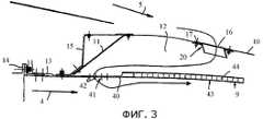
на фиг.3 показан частичный вид в увеличенном масштабе сопла, представленного на фиг.2;figure 3 shows a partial view in enlarged scale of the nozzle shown in figure 2;
на фиг.4 представлен в аксонометрии вид спереди сопла первого контура в соответствии со вторым вариантом осуществления;4 is a perspective view of a front nozzle of a primary circuit in accordance with a second embodiment;
на фиг.5 показан вид сбоку сопла, представленного на фиг.4;figure 5 shows a side view of the nozzle shown in figure 4;
на фиг.6 показан поперечный разрез сопла, представленного на фиг.4;figure 6 shows a cross section of the nozzle shown in figure 4;
на фиг.7 показан в аксонометрии вид воздухозаборника для сопла, представленного фиг.4;in Fig.7 shows a perspective view of the air intake for the nozzle shown in Fig.4;
на фиг.8 показан вид сверху воздухозаборника, представленного на фиг.7;on Fig shows a top view of the air intake shown in Fig.7;
на фиг.9 показан вид в разрезе воздухозаборника, представленного на фиг.7.in Fig.9 shows a sectional view of the air intake shown in Fig.7.
Турбореактивный двигатель 1, показанный на фиг.1, в целом содержит гондолу 2, охватывающую двухконтурный двигатель 3, содержащий камеру сгорания 3b.The turbojet engine 1 shown in FIG. 1 generally comprises a nacelle 2 enclosing a bypass engine 3 comprising a combustion chamber 3b.
Посредством вращения лопастей вентилятора 3а, двигатель 3 создает на выходе из гондолы 2 два воздушных потока, а именно поток 4 горячего воздуха, выходящий из камеры сгорания 3b, и поток 5 холодного воздуха, или, так называемый, вторичный поток, который циркулирует снаружи двигателя между внутренней стенкой 7 гондолы 2 и наружной стенкой кожуха 8. окружающего двигатель 3. Таким образом, поток 4 горячего воздуха имеет высокую температуру порядка 750°С, а поток 5 холодного воздуха - заметно меньшую температуру, составляющую около 100°С.By rotating the fan blades 3a, the engine 3 creates two air flows at the exit of the nacelle 2, namely the
Эти два потока, 4 и 5, выбрасываются из турбореактивного двигателя 1 через заднюю часть гондолы 2. Точнее говоря, поток горячего воздуха 4 выбрасывается через реактивное сопло 6, называемое здесь соплом первого контура, закрепленное на выходе камеры сгорания 3b.These two streams, 4 and 5, are ejected from the turbojet engine 1 through the rear of the nacelle 2. More precisely, the
Как показано на фиг.2 и 3, сопло 6 первого контура имеет внутреннюю стенку 9, которую омывает поток 4 горячего воздуха, и наружную стенку 10, вдоль которой протекает поток 5 холодного воздуха. Внутренняя стенка 9 и наружная стенка 10 смыкаются в задней части сопла 6 первого контура, а спереди соединены друг с другом посредством ребра жесткости 11. Таким образом, элементы 9, 10 и 11 ограничивают некоторое внутреннее пространство 12.As shown in FIGS. 2 and 3, the
Крепление сопла 6 первого контура к задней части двигателя 3 выполнено посредством крепежного фланца 13, являющегося продолжением внутренней стенки 9, и привинченного к крепежному фланцу 14 двигателя 3.The
Кроме того, наружная стенка 10 слегка выдается вперед, за ребро жесткости 11, заканчиваясь уголком 15, не соединенным с ребром жесткости 11 и выполненным из гибких листов, обеспечивающих соединение с передним концом кожуха 8 двигателя.In addition, the
Наружная стенка 10 изготовлена в виде листа из материала beta21s, в котором выполнены отверстия 16, в каждое из которых установлено по одному воздухозаборнику, закрепленному гайками 17. Эти отверстия 16 выполнены таким образом, чтобы они располагались под углом примерно 45° по обе стороны от точки крепления гондолы 2 и двигателя 3.The
Упомянутый выше материал beta21s представляет собой титановый сплав производства компании TIMET, известный под коммерческим названием TIMETAL21S. Этот материал, в частности, подходит для авиастроения благодаря его отличным механических свойствам и малой плотности, которая приблизительно в два раза меньше плотности инконеля. Благодаря использованию этого материала достигается существенное снижение массы. Однако, учитывая, что крепежные фланцы 13, 14 и ребро жесткости 11 подвергаются на выходе камеры сгорания 3b прямому воздействию потока 4 горячего воздуха, их всегда выполняют из инконеля. Кроме того, следует понимать, что как инконель, так и beta21s приведены здесь исключительно в качестве примера, поскольку они широко применяются в данной отрасли, однако применение материалов, необходимых для устройства согласно изобретению, никоим образом не ограничивается этими примерами.The beta21s material mentioned above is a TIMET titanium alloy known under the trade name TIMETAL21S. This material, in particular, is suitable for the aircraft industry due to its excellent mechanical properties and low density, which is approximately half the density of the inconel. Thanks to the use of this material, a significant reduction in mass is achieved. However, given that the
В соответствии с первым вариантом осуществления изобретения, представленным на фиг.2 и 3, в качестве воздухозаборников применены воздухозаборники 20 статического типа, называемые так по той причине, что они не выходят за пределы аэродинамических линий тока потока 5 холодного воздуха вдоль наружной стенки 10 сопла 6 первого контура. Такой статический воздухозаборник 20 содержит с одной стороны рамку 21, определяющую отверстие 22 и имеющую две боковых лапки 23, через которые проходят гайки 17 для крепления воздухозаборника 20 к верхней стенке 10, а с другой стороны - стенку 24, наклоненную относительно плоскости рамки 21 и предназначенную направлять поток 5 холодного воздуха, поступающего в статический воздухозаборник 20. Эта наклонная стенка 24 прикреплена спереди рамки 21 относительно направления потока 5 холодного воздуха и ограничена боковыми стенками 25. Длина и наклон указанной наклонной стенки 24 выбраны такими, чтобы обеспечивать забор и направление надлежащего количества холодного воздуха 5.In accordance with the first embodiment of the invention shown in FIGS. 2 and 3,
Во втором варианте осуществления заявленного изобретения, представленном на фиг.4-9, применены динамические воздухозаборники 30. Динамический воздухозаборник 30 отличается от статического воздухозаборника 20 лишь тем, что он имеет верхний элемент 31, перекрывающий заднюю часть рамки 21 и выходящий за пределы аэродинамических линий. Этот верхний элемент 31 имеет кромку 32, профилированную таким образом, чтобы создавать препятствие для потока холодного воздуха 5, направляя его к отверстию 22.In the second embodiment of the claimed invention, shown in figures 4-9,
Тип воздухозаборника - статический воздухозаборник 20 или динамический воздухозаборник 30 - выбирают, исходя из количества холодного воздуха 5, которое они позволяют захватить, и требований создания избыточного давления во внутреннем пространстве 12 сопла 6 первого контура.The type of air intake —
Внутреннюю стенку 9 выполняют также из листового элемента 40 изготовленного из материала beta21s, который легче инконеля, но обладает меньшей термостойкостью. Как раскрыто выше, внутренняя стенка 9 предназначена для контакта с потоком 4 горячего воздуха, поэтому нежелательно, чтобы она подвергалась его прямому воздействию без использования системы охлаждения.The
Для того чтобы повысить термостойкость внутренней стенки 9, листовой элемент 40 с одной стороны имеет зону 41 вентиляции, выполненную в виде сетки из просверленных отверстий 42, образующих устройство для распределения охлаждающего воздуха. Кроме того, листовой элемент 40 имеет зону 43 глушения шума, находящуюся по направлению потока 4 горячего воздуха за зоной 41 вентиляции и содержащую звукопоглощающую многослойную панель 44, ориентированную в направлении потока 4 горячего воздуха. Уменьшение массы, достигаемое вследствие применения материала beta21s, позволяет установить такую многослойную панель 44, которая в случае ее выполнения из инконеля привела бы к излишнему утяжелению конструкции.In order to increase the heat resistance of the
Во время работы поток 4 горячего воздуха из выходного отверстия камеры сгорания 3b поступает внутрь сопла 6 первого контура вдоль нижней стенки 9, в то время как поток 5 холодного воздуха после прохождения между внутренней стенкой 7 гондолы 2 и наружной стенкой кожуха 8 протекает снаружи сопла 6 первого контура вдоль верхней стенки 10.During operation, the
Проходя вдоль верхней стенки 10, поток 5 холодного воздуха наталкивается на статические или динамические воздухозаборники, соответственно, 20 или 30, в зависимости от выбранного варианта осуществления, и поступает во внутреннее пространство 12, давление в котором повышается.Passing along the
Течение потока 4 горячего воздуха возле нижней стенки 9 создает разрежение на уровне отверстий 42 зоны 41 вентиляции, в результате чего происходит выход холодного воздуха, находящегося во внутреннем пространстве 12 под более высоким давлением. При этом указанный воздух перемещается вдоль нижней стенки 9, образуя слой холодной текучей среды между указанной стенкой и потоком 4 горячего воздуха.The flow of the
Здесь следует заметить, что сетка из просверленных отверстий 42 выполнена таким образом, чтобы холодный воздух, находящийся во внутреннем пространстве 12, выходил и протекал как можно ближе к нижней стенке 9.It should be noted here that the grid of the drilled
Кроме того, в раскрытом здесь варианте осуществления, именно указанное внутреннее пространство 12 играет роль канала между статическими или динамическими воздухозаборниками, соответственно 20 или 30, и отверстиями 42. Однако вполне возможно выполнить специальный канал, например, в виде трубы, обеспечивающей такое соединение. В этом случае, поскольку объем такого канала меньше, легче обеспечить требуемое избыточное давление, при этом в тех случаях, где было необходимо применение динамического воздухозаборника 30, будет достаточно статического воздухозаборника 20.In addition, in the embodiment disclosed here, it is said
Кроме того, раскрытые здесь варианты осуществления предусматривают выполнение сетки из просверленных отверстий. Должно быть понятно, что можно также выполнить отверстия другой формы, - например прорези, либо выполнить ряд отверстий, каждое из которых будет связано со своим собственным каналом для прохода воздуха. Таким образом, признак «сетка из просверленных отверстий» в целом определен применительно к распределению всего холодного воздуха, подводимого на уровень нижней стенки 9, а не для каждого канала для прохода воздуха по отдельности.In addition, embodiments disclosed herein provide for meshing from drilled holes. It should be clear that it is also possible to make holes of a different shape, for example, slots, or to make a series of holes, each of which will be connected to its own channel for the passage of air. Thus, the sign “mesh of drilled holes” is generally defined in relation to the distribution of all cold air supplied to the level of the
Хотя изобретение было раскрыто выше со ссылками на конкретные варианты его осуществления, совершенно очевидно, что оно никоим образом не ограничивается этими примерами и охватывает самые разнообразные технические эквиваленты описанных здесь средств, а также их возможные комбинации, при условии, что они соответствуют заявленному объему изобретения.Although the invention has been disclosed above with reference to specific options for its implementation, it is obvious that it is in no way limited to these examples and covers a wide variety of technical equivalents of the agents described here, as well as their possible combinations, provided that they correspond to the claimed scope of the invention.
Claims (10)
Translated fromRussianApplications Claiming Priority (2)
| Application Number | Priority Date | Filing Date | Title |
|---|---|---|---|
| FR0407881AFR2873167B1 (en) | 2004-07-15 | 2004-07-15 | DEVICE FOR COOLING THE PRIMARY PIPE OF A DOUBLE FLOW TURBOJETACTOR |
| FR0407881 | 2004-07-15 |
Publications (2)
| Publication Number | Publication Date |
|---|---|
| RU2007104966A RU2007104966A (en) | 2008-08-20 |
| RU2397350C2true RU2397350C2 (en) | 2010-08-20 |
Family
ID=34947698
Family Applications (1)
| Application Number | Title | Priority Date | Filing Date |
|---|---|---|---|
| RU2007104966/06ARU2397350C2 (en) | 2004-07-15 | 2005-05-17 | Device to cool two-circuit turbojet engine first circuit |
Country Status (6)
| Country | Link |
|---|---|
| US (1) | US7866141B2 (en) |
| EP (1) | EP1766219A1 (en) |
| CA (1) | CA2564508A1 (en) |
| FR (1) | FR2873167B1 (en) |
| RU (1) | RU2397350C2 (en) |
| WO (1) | WO2006016017A1 (en) |
Families Citing this family (18)
| Publication number | Priority date | Publication date | Assignee | Title |
|---|---|---|---|---|
| FR2905984B1 (en)* | 2006-09-20 | 2011-12-30 | Turbomeca | GAS TURBINE HELICOPTER ENGINE WITH REDUCED SOUND TRANSMISSION BY ACOUSTIC TREATMENT OF EJECTOR |
| GB2443830B (en) | 2006-11-15 | 2010-01-20 | Rolls Royce Plc | Cowling arrangement |
| FR2930324B1 (en)* | 2008-04-17 | 2011-06-17 | Snecma | DEVICE FOR COOLING A WALL |
| FR2949820B1 (en)* | 2009-09-04 | 2011-10-14 | Aircelle Sa | STRUCTURING ASSEMBLY FOR AN EJECTION TUBE. |
| US8621842B2 (en) | 2010-05-05 | 2014-01-07 | Hamilton Sundstrand Corporation | Exhaust silencer convection cooling |
| FR2961175B1 (en)* | 2010-06-14 | 2013-01-04 | Aircelle Sa | TURBOREACTOR NACELLE |
| FR2987078B1 (en)* | 2012-02-17 | 2016-11-25 | Snecma Propulsion Solide | REAR BODY ASSEMBLY OF AERONAUTICAL GAS TURBINE ENGINE |
| US10837367B2 (en)* | 2012-02-28 | 2020-11-17 | Raytheon Technologies Corporation | Acoustic treatment in an unducted area of a geared turbomachine |
| US9856745B2 (en)* | 2012-02-28 | 2018-01-02 | United Technologies Corporation | Acoustic treatment in an unducted area of a geared turbomachine |
| FR3004494B1 (en)* | 2013-04-15 | 2018-01-19 | Safran Nacelles | TUYERE FOR AIRCRAFT TURBOPROPULSER WITH NON-CARBONATED BLOWER |
| US20150267644A1 (en)* | 2014-03-19 | 2015-09-24 | The Boeing Company | Integrated Primary Nozzle |
| US10385868B2 (en)* | 2016-07-05 | 2019-08-20 | General Electric Company | Strut assembly for an aircraft engine |
| PL421120A1 (en) | 2017-04-04 | 2018-10-08 | General Electric Company Polska Spolka Z Ograniczona Odpowiedzialnoscia | Turbine engine and component parts to be used in it |
| CA3000376A1 (en)* | 2017-05-23 | 2018-11-23 | Rolls-Royce Corporation | Turbine shroud assembly having ceramic matrix composite track segments with metallic attachment features |
| US10605409B2 (en)* | 2017-06-30 | 2020-03-31 | The Boeing Company | Additively manufactured pressurization diffusers |
| FR3082238A1 (en)* | 2018-06-11 | 2019-12-13 | Airbus Operations | PRIMARY NOZZLE OF A PRIMARY EJECTION DUCT OF A TURBOMACHINE |
| US11085398B2 (en)* | 2019-03-12 | 2021-08-10 | Rohr, Inc. | Core air flow to equalize temperature differential |
| FR3100845B1 (en) | 2019-09-13 | 2022-07-08 | Safran Nacelles | Outer nozzle member for turbomachine |
Citations (6)
| Publication number | Priority date | Publication date | Assignee | Title |
|---|---|---|---|---|
| US2988302A (en)* | 1959-01-14 | 1961-06-13 | Gen Sound Control Inc | Silencing means for aircraft |
| US4137992A (en)* | 1976-12-30 | 1979-02-06 | The Boeing Company | Turbojet engine nozzle for attenuating core and turbine noise |
| US4826106A (en)* | 1987-02-18 | 1989-05-02 | Grumman Aerospace Corporation | Advanced composite aircraft cowl |
| US4944362A (en)* | 1988-11-25 | 1990-07-31 | General Electric Company | Closed cavity noise suppressor |
| RU2154133C2 (en)* | 1996-08-14 | 2000-08-10 | Испано Сюиза | Ventilated multilayer panel with cellular filler |
| RU2230208C2 (en)* | 2002-06-05 | 2004-06-10 | Открытое акционерное общество "Авиадвигатель" | Sound-absorbing device in two-circuit turbojet engine |
Family Cites Families (8)
| Publication number | Priority date | Publication date | Assignee | Title |
|---|---|---|---|---|
| US2826895A (en)* | 1953-09-03 | 1958-03-18 | Fairchild Engine & Airplane | Bearing cooling system |
| US3215172A (en)* | 1962-12-24 | 1965-11-02 | Nilsson Robbins & Anderson | Jet engine noise suppressor with shroud for aspiration of air into exhaust stream |
| US3721389A (en)* | 1971-06-10 | 1973-03-20 | Boeing Co | Exit nozzle assemblies for gas turbine power plants |
| US5167118A (en)* | 1989-11-06 | 1992-12-01 | Nordam | Jet engine fixed plug noise suppressor |
| US5269139A (en)* | 1991-06-28 | 1993-12-14 | The Boeing Company | Jet engine with noise suppressing mixing and exhaust sections |
| US5184455A (en)* | 1991-07-09 | 1993-02-09 | The United States Of America As Represented By The Secretary Of The Air Force | Ceramic blanket augmentor liner |
| DE69526615T2 (en)* | 1994-09-14 | 2002-11-28 | Mitsubishi Jukogyo K.K., Tokio/Tokyo | Wall structure for the outlet nozzle of a supersonic jet engine |
| FR2834533B1 (en) | 2002-01-10 | 2004-10-29 | Hurel Hispano Le Havre | DEVICE FOR COOLING THE COMMON NOZZLE ON A NACELLE |
- 2004
- 2004-07-15FRFR0407881Apatent/FR2873167B1/ennot_activeExpired - Fee Related
- 2005
- 2005-05-17USUS11/630,032patent/US7866141B2/ennot_activeExpired - Fee Related
- 2005-05-17RURU2007104966/06Apatent/RU2397350C2/ennot_activeIP Right Cessation
- 2005-05-17EPEP05773042Apatent/EP1766219A1/ennot_activeWithdrawn
- 2005-05-17CACA002564508Apatent/CA2564508A1/ennot_activeAbandoned
- 2005-05-17WOPCT/FR2005/001221patent/WO2006016017A1/enactiveApplication Filing
Patent Citations (6)
| Publication number | Priority date | Publication date | Assignee | Title |
|---|---|---|---|---|
| US2988302A (en)* | 1959-01-14 | 1961-06-13 | Gen Sound Control Inc | Silencing means for aircraft |
| US4137992A (en)* | 1976-12-30 | 1979-02-06 | The Boeing Company | Turbojet engine nozzle for attenuating core and turbine noise |
| US4826106A (en)* | 1987-02-18 | 1989-05-02 | Grumman Aerospace Corporation | Advanced composite aircraft cowl |
| US4944362A (en)* | 1988-11-25 | 1990-07-31 | General Electric Company | Closed cavity noise suppressor |
| RU2154133C2 (en)* | 1996-08-14 | 2000-08-10 | Испано Сюиза | Ventilated multilayer panel with cellular filler |
| RU2230208C2 (en)* | 2002-06-05 | 2004-06-10 | Открытое акционерное общество "Авиадвигатель" | Sound-absorbing device in two-circuit turbojet engine |
Also Published As
| Publication number | Publication date |
|---|---|
| WO2006016017A1 (en) | 2006-02-16 |
| US7866141B2 (en) | 2011-01-11 |
| EP1766219A1 (en) | 2007-03-28 |
| FR2873167B1 (en) | 2007-11-02 |
| FR2873167A1 (en) | 2006-01-20 |
| US20080044280A1 (en) | 2008-02-21 |
| RU2007104966A (en) | 2008-08-20 |
| CA2564508A1 (en) | 2006-02-16 |
Similar Documents
| Publication | Publication Date | Title |
|---|---|---|
| RU2397350C2 (en) | Device to cool two-circuit turbojet engine first circuit | |
| RU2379536C1 (en) | Turbofan gas turbine engine with reduced jet noise | |
| US5467747A (en) | Noise suppression enclosure for an engine | |
| US6592078B2 (en) | Process for de-icing an air intake cowling of a reaction motor and device for practicing the same | |
| US7286348B2 (en) | Housing assembly for a computer | |
| US4749150A (en) | Turbofan duct with noise suppression and boundary layer control | |
| RU2494015C2 (en) | Aircraft nacelle air intake and engine with such air intake | |
| US3227240A (en) | Air mingling sound suppressor for jet engine | |
| US5339622A (en) | Gas turbine engine with improved water ingestion prevention | |
| BRPI0616528A2 (en) | method to attenuate the jet noise of a turboprop engine and turboprop engine | |
| US5906097A (en) | Engine flow control device | |
| CN111189127B (en) | Noise elimination and sound insulation device for air conditioner outdoor unit | |
| CA1198682A (en) | Noise absorption apparatus | |
| US4503931A (en) | Noise suppressing, air cooled enclosure for an engine | |
| CN113811487A (en) | Nacelle air inlet and nacelle comprising such an air inlet | |
| US20220282669A1 (en) | Nacelle air intake provided with a mixed ice protection system | |
| US20030113205A1 (en) | Air intake system of a propeller-turbine engine | |
| WO1993004272A1 (en) | Noise suppression enclosure for an engine | |
| SE513093C2 (en) | Fan module for cleanroom applications | |
| JPH1190149A (en) | Air intake structure of air cleaner for automobile | |
| US5672102A (en) | Dust reduction system for electronic enclosures | |
| WO1991018199A1 (en) | Variable cycle gas turbine engine for supersonic aircraft | |
| CN111465557A (en) | Air inlet lip for a turbojet engine nacelle | |
| CN214223451U (en) | Heat pump machine for swimming pool | |
| CN211231038U (en) | Bladeless fan device |
Legal Events
| Date | Code | Title | Description |
|---|---|---|---|
| MM4A | The patent is invalid due to non-payment of fees | Effective date:20140518 |