RU2396619C1 - Adapter of electric power cable, and manufacturing method thereof - Google Patents
Adapter of electric power cable, and manufacturing method thereofDownload PDFInfo
- Publication number
- RU2396619C1 RU2396619C1RU2009106961/09ARU2009106961ARU2396619C1RU 2396619 C1RU2396619 C1RU 2396619C1RU 2009106961/09 ARU2009106961/09 ARU 2009106961/09ARU 2009106961 ARU2009106961 ARU 2009106961ARU 2396619 C1RU2396619 C1RU 2396619C1
- Authority
- RU
- Russia
- Prior art keywords
- cable
- insulation
- semiconducting
- thickness
- electrical
- Prior art date
Links
- 238000004519manufacturing processMethods0.000title1
- 238000009413insulationMethods0.000claimsabstractdescription65
- 239000004020conductorSubstances0.000claimsdescription41
- 238000010292electrical insulationMethods0.000claimsdescription16
- 239000004065semiconductorSubstances0.000claimsdescription9
- 229920002379silicone rubberPolymers0.000claimsdescription9
- 238000009434installationMethods0.000claimsdescription5
- 239000004945silicone rubberSubstances0.000claimsdescription3
- 230000003247decreasing effectEffects0.000abstract1
- 230000000694effectsEffects0.000abstract1
- 230000005611electricityEffects0.000abstract1
- 230000002787reinforcementEffects0.000abstract1
- 239000000126substanceSubstances0.000abstract1
- 230000002459sustained effectEffects0.000abstract1
- 239000010410layerSubstances0.000description18
- 229920001296polysiloxanePolymers0.000description14
- 230000005684electric fieldEffects0.000description9
- 239000000463materialSubstances0.000description9
- 238000000034methodMethods0.000description4
- 229920004482WACKER®Polymers0.000description3
- 239000000049pigmentSubstances0.000description3
- -1polyethylenePolymers0.000description3
- 229920000181Ethylene propylene rubberPolymers0.000description2
- 239000004698PolyethyleneSubstances0.000description2
- VYPSYNLAJGMNEJ-UHFFFAOYSA-NSilicium dioxideChemical compoundO=[Si]=OVYPSYNLAJGMNEJ-UHFFFAOYSA-N0.000description2
- 230000001154acute effectEffects0.000description2
- 239000000654additiveSubstances0.000description2
- 230000015556catabolic processEffects0.000description2
- 239000002131composite materialSubstances0.000description2
- 229920003020cross-linked polyethylenePolymers0.000description2
- 239000004703cross-linked polyethyleneSubstances0.000description2
- 239000011810insulating materialSubstances0.000description2
- 239000007788liquidSubstances0.000description2
- 239000000203mixtureSubstances0.000description2
- 229920000573polyethylenePolymers0.000description2
- 229920000260silasticPolymers0.000description2
- YJVBLROMQZEFPA-UHFFFAOYSA-Lacid red 26Chemical compound[Na+].[Na+].CC1=CC(C)=CC=C1N=NC1=C(O)C(S([O-])(=O)=O)=CC2=CC(S([O-])(=O)=O)=CC=C12YJVBLROMQZEFPA-UHFFFAOYSA-L0.000description1
- 230000000996additive effectEffects0.000description1
- 230000002411adverseEffects0.000description1
- 239000000443aerosolSubstances0.000description1
- 239000006229carbon blackSubstances0.000description1
- 229920006217cellulose acetate butyratePolymers0.000description1
- 239000002270dispersing agentSubstances0.000description1
- 239000000975dyeSubstances0.000description1
- 238000005516engineering processMethods0.000description1
- 238000001125extrusionMethods0.000description1
- 239000000945fillerSubstances0.000description1
- 239000003063flame retardantSubstances0.000description1
- 239000000499gelSubstances0.000description1
- 210000004907glandAnatomy0.000description1
- 238000010438heat treatmentMethods0.000description1
- 238000002347injectionMethods0.000description1
- 239000007924injectionSubstances0.000description1
- 230000003993interactionEffects0.000description1
- 238000012986modificationMethods0.000description1
- 230000004048modificationEffects0.000description1
- 238000000465mouldingMethods0.000description1
- 230000002093peripheral effectEffects0.000description1
- 229920000139polyethylene terephthalatePolymers0.000description1
- 239000005020polyethylene terephthalateSubstances0.000description1
- 229920000915polyvinyl chloridePolymers0.000description1
- 239000004800polyvinyl chlorideSubstances0.000description1
- 238000003825pressingMethods0.000description1
- 239000011241protective layerSubstances0.000description1
- 230000003014reinforcing effectEffects0.000description1
- 239000005060rubberSubstances0.000description1
- 239000000377silicon dioxideSubstances0.000description1
- 229920005573silicon-containing polymerPolymers0.000description1
- 238000009966trimmingMethods0.000description1
Images


Classifications
- H—ELECTRICITY
- H01—ELECTRIC ELEMENTS
- H01B—CABLES; CONDUCTORS; INSULATORS; SELECTION OF MATERIALS FOR THEIR CONDUCTIVE, INSULATING OR DIELECTRIC PROPERTIES
- H01B9/00—Power cables
- H—ELECTRICITY
- H02—GENERATION; CONVERSION OR DISTRIBUTION OF ELECTRIC POWER
- H02G—INSTALLATION OF ELECTRIC CABLES OR LINES, OR OF COMBINED OPTICAL AND ELECTRIC CABLES OR LINES
- H02G15/00—Cable fittings
- H02G15/02—Cable terminations
- H—ELECTRICITY
- H01—ELECTRIC ELEMENTS
- H01B—CABLES; CONDUCTORS; INSULATORS; SELECTION OF MATERIALS FOR THEIR CONDUCTIVE, INSULATING OR DIELECTRIC PROPERTIES
- H01B7/00—Insulated conductors or cables characterised by their form
- H01B7/02—Disposition of insulation
- H—ELECTRICITY
- H02—GENERATION; CONVERSION OR DISTRIBUTION OF ELECTRIC POWER
- H02G—INSTALLATION OF ELECTRIC CABLES OR LINES, OR OF COMBINED OPTICAL AND ELECTRIC CABLES OR LINES
- H02G15/00—Cable fittings
- H02G15/02—Cable terminations
- H02G15/04—Cable-end sealings
- H—ELECTRICITY
- H02—GENERATION; CONVERSION OR DISTRIBUTION OF ELECTRIC POWER
- H02G—INSTALLATION OF ELECTRIC CABLES OR LINES, OR OF COMBINED OPTICAL AND ELECTRIC CABLES OR LINES
- H02G15/00—Cable fittings
- H02G15/08—Cable junctions
- H02G15/18—Cable junctions protected by sleeves, e.g. for communication cable
- H02G15/182—Cable junctions protected by sleeves, e.g. for communication cable held in expanded condition in radial direction prior to installation
- H02G15/1826—Cable junctions protected by sleeves, e.g. for communication cable held in expanded condition in radial direction prior to installation on a removable hollow core, e.g. a tube
- H02G15/1833—Cable junctions protected by sleeves, e.g. for communication cable held in expanded condition in radial direction prior to installation on a removable hollow core, e.g. a tube formed of helically wound strip with adjacent windings, which are removable by applying a pulling force to a strip end
- H—ELECTRICITY
- H02—GENERATION; CONVERSION OR DISTRIBUTION OF ELECTRIC POWER
- H02G—INSTALLATION OF ELECTRIC CABLES OR LINES, OR OF COMBINED OPTICAL AND ELECTRIC CABLES OR LINES
- H02G15/00—Cable fittings
- H02G15/08—Cable junctions
- H02G15/18—Cable junctions protected by sleeves, e.g. for communication cable
- H02G15/184—Cable junctions protected by sleeves, e.g. for communication cable with devices for relieving electrical stress
Landscapes
- Cable Accessories (AREA)
Abstract
Description
Translated fromRussianУровень техникиState of the art
Настоящее изобретение в общем относится к управлению напряженностью электрического поля в силовых электрических кабелях, а конкретнее, к изделию и способу управления напряженностью электрического поля в области сильного электрического поля, обусловленного электрическими силовыми кабелями и связанными с ними комплектующими.The present invention generally relates to controlling an electric field in power electric cables, and more particularly, to an article and method for controlling an electric field in a strong electric field due to electric power cables and related components.
Используемое здесь выражение «высокое напряжение», как правило, относится к напряжениям достаточно высоким, чтобы вызвать пробой кабельной изоляции в непрерывной оболочке кабеля. Не ограничивая объем настоящего изобретения, в некоторых вариантах осуществления выражение «высокое напряжение», как правило, относится к напряжениям 50 кВ и более, хотя настоящее изобретение также выгодно использовать и с меньшими напряжениями.The term “high voltage” as used herein generally refers to voltages high enough to cause breakdown of cable insulation in a continuous cable sheath. Without limiting the scope of the present invention, in some embodiments, the expression “high voltage” generally refers to voltages of 50 kV or more, although the present invention is also advantageous to use with lower voltages.
Стандартный кабель высокого напряжения включает в себя центральный электрический проводник, полупроводящий слой (также упоминаемый здесь как оболочка проводника), окружающий электрический проводник, электроизоляционный слой, закрывающий оболочку проводника, и полупроводящий слой (также упоминаемый здесь как оболочка изоляции) поверх изоляционного слоя. При обрезке такого кабеля принято удалять или срезать каждый последующий слой кабеля, чтобы вскрыть слой, расположенный ниже. Срезание полупроводящих кабельных оболочек вызывает неоднородность электрического поля в кабеле, приводящую к высокой напряженности электрического поля на срезанных концах оболочек. Высокая электрическая напряженность может вызывать появление электрических разрядов, которые, в свою очередь, стремятся нарушить изоляционный слой кабеля.A standard high voltage cable includes a central electrical conductor, a semiconducting layer (also referred to here as a conductor sheath), a surrounding electrical conductor, an electrical insulating layer covering the conductor, and a semiconducting layer (also referred to as an insulating sheath) on top of the insulating layer. When trimming such a cable, it is customary to remove or cut each subsequent layer of cable to open the layer below. Cutting off the semiconducting cable sheaths causes an electric field inhomogeneity in the cable, resulting in high electric field strength at the sheared ends of the sheaths. High electrical voltage can cause electrical discharges, which, in turn, tend to break the insulation layer of the cable.
Толщина изоляционного слоя кабеля зависит от категории напряжения кабеля, причем более высоковольтные кабели имеют более толстый изоляционный слой. Зачастую, толщина изоляционного слоя может быть уменьшена, если в качестве изолирующего использован материал высокого качества (т.е. более чистый). Например, в США толщина изоляции у кабеля категории 69 кВ приблизительно равна 650 мил (тысячных долей дюйма). Подобный кабель в Европе - кабель категории 72 кВ - имеет толщину изоляции, изменяющуюся от 400 мил до 470 мил. Уменьшенная толщина изоляции обеспечивает такие преимущества, как сниженные размер, вес и стоимость кабеля, обусловленные сокращением количества используемого изолирующего материала.The thickness of the cable insulating layer depends on the voltage category of the cable, with higher voltage cables having a thicker insulation layer. Often, the thickness of the insulating layer can be reduced if high quality material (i.e., cleaner) is used as the insulating material. For example, in the United States, the insulation thickness of a 69 kV category cable is approximately 650 mil (thousandths of an inch). A similar cable in Europe - a cable category of 72 kV - has an insulation thickness ranging from 400 mils to 470 mils. The reduced thickness of the insulation provides benefits such as reduced cable size, weight and cost due to the reduction in the amount of insulating material used.
Несмотря на преимущества, обеспечиваемые уменьшением толщины изоляционного слоя, уменьшенная толщина изоляции к тому же требует, чтобы кабельная арматура, такая как кабельные выводы, выдерживала повышенную электрическую напряженность на разрывах кабельной оболочки. Если это не учтено должным образом, дополнительная электрическая напряженность может приводить к повреждению кабеля и (или) кабельной арматуры. В некоторых случаях дополнительная электрическая напряженность компенсируется заменой кабельной арматуры, предназначенной для кабеля с более высокой категорией напряжения (к примеру, использование арматуры, рассчитанной на 138 кВ, в кабеле на 110 кВ, имеющем уменьшенную толщину изоляции). Несмотря на такую работу по замене арматуры, разница в стоимости арматуры с повышенным номиналом является зачастую значимой. Соответственно, желательной является конструкция, которая позволяет использовать кабели, имеющие уменьшенную толщину изоляции, с арматурой существующих кабелей в той же категории напряжения.Despite the advantages provided by reducing the thickness of the insulating layer, the reduced thickness of the insulation also requires that cable fittings, such as cable outlets, withstand increased electrical stress at the breaks of the cable sheath. If this is not taken into account properly, additional electrical voltage can lead to damage to the cable and / or cable accessories. In some cases, the additional electrical voltage is compensated by replacing cable fittings designed for a cable with a higher voltage category (for example, using fittings designed for 138 kV in a 110 kV cable having a reduced insulation thickness). Despite this kind of valve replacement work, the difference in the cost of valves with a higher nominal value is often significant. Accordingly, a design that allows the use of cables having a reduced insulation thickness with fittings of existing cables in the same voltage category is desirable.
Сущность изобретенияSUMMARY OF THE INVENTION
В одном объекте описанное здесь изобретение обеспечивает адаптер управления электрической напряженностью в электрическом силовом кабеле такого типа, который включает в себя: внутренний проводник; оболочку проводника, покрывающую электрический проводник; электроизоляцию с уменьшенной толщиной, окружающую оболочку проводника; и полупроводящую оболочку, окружающую изоляцию. В одном варианте осуществления адаптер содержит продольную изолирующую деталь, имеющую первый конец и второй конец; и полупроводящую деталь, соприкасающуюся с первым концом изолирующей детали; при этом изолирующая деталь выполнена с возможностью перекрытия открытой части окружающей кабель электроизоляции с уменьшенной толщиной, и при этом полупроводящая деталь выполнена с возможностью перекрытия открытой части кабельной полупроводящей оболочки.In one aspect, the invention described herein provides an adapter for controlling electrical tension in an electrical power cable of a type that includes: an internal conductor; a conductor sheath covering the electrical conductor; reduced thickness electrical insulation surrounding the conductor sheath; and a semiconducting shell surrounding the insulation. In one embodiment, the adapter comprises a longitudinal insulating part having a first end and a second end; and a semiconductor part in contact with the first end of the insulating part; wherein the insulating part is configured to overlap the open part of the electrical insulation surrounding the cable with a reduced thickness, and the semiconducting part is configured to overlap the open part of the cable semiconducting sheath.
В другом объекте описанное здесь изобретение обеспечивает концевую систему для электрического силового кабеля того типа, который включает в себя: внутренний проводник; оболочку проводника, покрывающую электрический проводник; электроизоляцию с уменьшенной толщиной, покрывающую оболочку проводника; и полупроводящую оболочку над изоляцией. В одном варианте осуществления концевая система содержит вывод, выполненный с возможностью установки на кабель, имеющий по меньшей мере первую толщину изоляции; и адаптер, выполненный с возможностью установки на кабель, имеющий вторую толщину изоляции, причем вторая толщина изоляции меньше, чем первая толщина изоляции, при этом адаптер включает в себя изолирующую деталь, выполненную с возможностью перекрытия открытой части кабельной изоляции, и полупроводящую деталь, соприкасающуюся с изолирующей деталью и кабельной полупроводящей оболочкой.In another aspect, the invention described herein provides an end system for an electrical power cable of a type that includes: an internal conductor; a conductor sheath covering the electrical conductor; reduced thickness electrical insulation covering the conductor sheath; and a semiconducting shell over the insulation. In one embodiment, the end system comprises a terminal configured to be mounted on a cable having at least a first insulation thickness; and an adapter configured to be mounted on a cable having a second insulation thickness, the second insulation thickness being less than the first insulation thickness, the adapter including an insulating part configured to overlap the open portion of the cable insulation and a semiconducting part in contact with insulating part and cable semiconducting sheath.
В другом объекте описанное здесь изобретение обеспечивает способ снижения электрической напряженности в арматуре электрического силового кабеля. В одном варианте осуществления этот способ содержит этапы, на которых подготавливают электрический силовой кабель, включающий в себя внутренний проводник; оболочку проводника, окружающую электрический проводник; слой электроизоляции с уменьшенной толщиной, покрывающий оболочку проводника; и полупроводящую оболочку над изоляционным слоем; удаляют заранее заданную длину полупроводящей оболочки, чтобы открыть часть слоя кабельной изоляции, и удаляют меньшую заранее заданную длину открытой части слоя кабельной изоляции и оболочки проводника, чтобы открыть кабельный проводник; устанавливают адаптер поверх подготовленного кабеля, чтобы повысить общую эффективную толщину изоляции подготовленного кабеля; и устанавливают кабельную арматуру поверх адаптера.In another aspect, the invention described herein provides a method of reducing electrical stress in an armature of an electrical power cable. In one embodiment, this method comprises the steps of preparing an electrical power cable including an inner conductor; a conductor sheath surrounding the electrical conductor; a layer of electrical insulation with a reduced thickness covering the sheath of the conductor; and a semiconducting shell over the insulating layer; removing a predetermined length of the semiconducting sheath to open part of the cable insulation layer, and removing a shorter predetermined length of the open part of the cable insulation layer and the conductor sheath to open the cable conductor; install the adapter on top of the prepared cable to increase the overall effective insulation thickness of the prepared cable; and install cable accessories on top of the adapter.
Краткое описание чертежейBrief Description of the Drawings
Варианты осуществления изобретения лучше понятны со ссылкой на нижеследующие чертежи. Элементы чертежей не обязательно масштабированы относительно друг друга. Одинаковые ссылочные позиции обозначают соответствующие сходные части.Embodiments of the invention are better understood with reference to the following drawings. Elements of the drawings are not necessarily scaled relative to each other. The same reference numbers indicate corresponding similar parts.
Фиг.1 является иллюстрацией электрического силового кабеля, подготовленного для установки адаптера управления напряженностью согласно изобретению.Figure 1 is an illustration of an electric power cable prepared for installation of a tension control adapter according to the invention.
Фиг.2А является изображением поперечного сечения одного варианта осуществления адаптера управления напряженностью согласно изобретению.2A is a cross-sectional view of one embodiment of a tension control adapter according to the invention.
Фиг.2В является изображением поперечного сечения адаптера управления напряженностью по Фиг.2А, расположенного на несущем сердечнике, согласно изобретению.Fig. 2B is a cross-sectional view of the tension control adapter of Fig. 2A located on a carrier core according to the invention.
Фиг.2С является изображением поперечного сечения адаптера управления напряженностью по Фиг.2А применительно к электрическому силовому кабелю согласно изобретению.Fig. 2C is a cross-sectional view of the tension control adapter of Fig. 2A as applied to an electric power cable according to the invention.
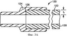
Фиг.3А является изображением поперечного сечения другого варианта осуществления адаптера управления напряженностью согласно изобретению.3A is a cross-sectional view of another embodiment of a tension control adapter according to the invention.
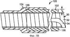
Фиг.3В является изображением поперечного сечения адаптера управления напряженностью по Фиг.3А, расположенного на несущем сердечнике, согласно варианту осуществления изобретения.Fig. 3B is a cross-sectional view of the tension control adapter of Fig. 3A located on a carrier core according to an embodiment of the invention.
Фиг.3С является изображением поперечного сечения адаптера управления напряженностью по Фиг.3А, применительно к электрическому силовому кабелю, согласно изобретению.Fig. 3C is a cross-sectional view of the tension control adapter of Fig. 3A, as applied to an electric power cable according to the invention.
Подробное описаниеDetailed description
В нижеследующем подробном описании предпочтительных вариантов осуществления делаются ссылки на прилагаемые чертежи, которые образуют часть данного описания и на которых показаны в качестве иллюстрации конкретные варианты осуществления, в которых может быть воплощено изобретение. Показанные варианты осуществления не предназначены исчерпывать все вариантами осуществления согласно изобретению. Следует понимать, что могут быть использованы и другие варианты осуществления, а структурные или логические изменения могут быть сделаны без отхода от объема настоящего изобретения. Например, хотя настоящее изобретение прежде всего описано применительно к концевой системе кабеля, оно также пригодно для воплощения с соединителями высоковольтных кабелей и другим высоковольтным оборудованием, в том числе электрическими вставками и проходниками. Поэтому нижеследующее подробное описание не должно пониматься в ограничительном смысле, а объем настоящего изобретения определяется приложенной формулой изобретения.In the following detailed description of preferred embodiments, reference is made to the accompanying drawings, which form part of this description and which show, by way of illustration, specific embodiments in which the invention may be embodied. The embodiments shown are not intended to exhaust all the embodiments according to the invention. It should be understood that other embodiments may be used, and structural or logical changes may be made without departing from the scope of the present invention. For example, although the present invention is primarily described in relation to a cable end system, it is also suitable for implementation with high voltage cable connectors and other high voltage equipment, including electrical inserts and bushings. Therefore, the following detailed description should not be construed in a limiting sense, and the scope of the present invention is defined by the appended claims.
На Фиг.1 показан типовой силовой кабель 10. Типовой силовой кабель 10 включает в себя центральный электрический проводник 12, полупроводящий слой 14 (также упоминаемый здесь как оболочка 14 проводника), окружающий электрический проводник 12, слой электроизоляции 16, покрывающий оболочку 14 проводника, и полупроводящий слой 18 (также упоминаемый здесь как оболочка 18 изоляции) поверх изоляции 16. Изоляция 16 может содержать такой материал как сшитый полиэтилен (XLPE), полиэтилен (РЕ) или этиленпропиленовый каучук (EPR), либо другие материалы, как известно в уровне техники. Дополнительные защитные слои (не показаны) могут дополнительно предусматриваться поверх оболочки 18 изоляции.1, a
Как описано здесь, понимается, что электроизоляция 16 кабеля 10 имеет уменьшенную толщину, которая в отсутствие добавочных мер управления электрической напряженностью требует использования арматуры кабеля более высокого класса напряжения, чем класс напряжения кабеля (к примеру, использования арматуры кабеля, рассчитанной на 138 кВ, с кабелем на 110 кВ, имеющим уменьшенную толщину изоляции). Такой кабель, имеющий уменьшенную толщину изоляции, может упоминаться как кабель с тонкой оболочкой. В отличие от этого, кабель, имеющий довольно толстую электроизоляцию, позволяющую использовать арматуру кабеля того же класса напряжения, что и класс напряжения данного кабеля, без использования добавочных мер управления электрической напряженностью упоминается здесь как стандартный кабель.As described here, it is understood that the
Как показано на Фиг.1, кабель 10 подготавливается для завершения путем удаления заранее заданной длины оболочки 14 проводника, такой же заранее заданной длины изоляции 16, покрывающей оболочку 14 проводника, и большей заранее заданной длины оболочки 18 изоляции, покрывающей изоляцию 16. Следует отметить, что масштаб чертежей искажен для простоты описания. Срезание оболочки 18 изоляции порождает неоднородность электрического поля, окружающего проводник 12, которая приводит к высокой напряженности электрического поля на срезанных концах оболочки 18 изоляции. Как описано выше, высокая электрическая напряженность может вызывать появление электрических разрядов, что, в свою очередь, может вызвать пробой в изоляции 16 и возможный отказ места соединения.As shown in FIG. 1,
В одном варианте осуществления управление электрической напряженностью кабеля 10, имеющего уменьшенную толщину электроизоляции 16, дополнено установкой изолирующего адаптера поверх изоляции 16, чтобы повысить общую эффективную толщину изоляции, окружающую проводник 12, а затем установкой кабельной арматуры поверх этого адаптера. В одном варианте осуществления общая эффективная толщина изоляции по меньшей мере такая же, как толщина изоляции стандартного кабеля.In one embodiment, controlling the electrical voltage of the
На Фиг.2А-2С изображен адаптер 20 согласно одному варианту осуществления изобретения. Адаптер 20 включает в себя продольную электрически изолирующую часть 22 и полупроводящую часть 24. Изолирующая часть 22 определяет исходную толщину tr и имеет первый конец 26 и второй конец 28. Полупроводящая часть 24 упирается в первый конец 26 и соприкасается с первым концом 26 изолирующей части 22. Концы изолирующей части 22 и полупроводящей части 24 сформированы так, чтобы избежать острых углов в областях высокой напряженности электрического поля. В варианте осуществления по Фиг.2А изолирующая часть 22 и полупроводящая часть 24 отлиты вместе для формирования единого или неразъемного адаптера 20.2A-2C show an
В одном варианте осуществления, как изображено на Фиг.2 В, эластично восстанавливающийся адаптер 20 поддерживается в радиально расширенном или предварительно растянутом состоянии на съемном жестком несущем сердечнике 30. В этом варианте осуществления адаптер 20 может в общем упоминаться как предварительно растянутая труба холодной усадки. В этом радиально расширенном состоянии изолирующая часть 22 определяет растянутую толщину ts, которая меньше, чем исходная толщина tr на Фиг.2А. Выражения «эластично восстанавливающийся», «эластично усаживающийся» и «холодной усадки» используются взаимозаменяемо для обозначения того, что изделие дает усадку при температурах приблизительно от примерно -20°С до примерно 50°С без дополнительного нагрева.In one embodiment, as depicted in FIG. 2B, the resiliently
На Фиг.2С адаптер 20 по Фиг.2А и 2В показан установленным на кабель 10 и далее имеющим кабельную арматуру 40, установленную поверх адаптера 20. Хотя в общем она изображена как концевая система, кабельная арматура 40 может быть любым типом известной арматуры, предназначенной для установки на кабель 10, и не ограничиваться концевой системой. Зачищенный проводник 12 подключается к наконечнику 42, который обжимается на проводнике 12. Изолирующая часть 22 выполнена с возможностью перекрытия и контактирования с зачищенной частью электроизоляции 16 с уменьшенной толщиной, окружающей кабельный проводник 12, что повышает общую эффективную толщину изоляции тонкостенного кабеля 10 до толщины, которая равна или больше, чем толщина изоляции стандартного кабеля, или, альтернативно, до толщины, которая снижает электрическую напряженность до уровня, который может выдержать кабель и комбинация кабеля с кабельной арматурой. В своем установленном состоянии изолирующая часть 22 определяет установленную толщину ti, которая обычно меньше, чем исходная толщина tr по Фиг.2А, и больше, чем растянутая толщина tsпо Фиг.2В. Полупроводящая часть 24 располагается так, чтобы проходить по срезанному концу оболочки 18 изоляции, и выполнена с возможностью перекрытия и контактирования с открытой частью оболочки 18 изоляции и для восстановления оболочки изоляции поверх кабельной изоляции 16 и изолирующей части 22 адаптера. Адаптер 20 использует геометрический рельеф напряженности, чтобы восстановить оболочку изоляции поверх композитного материала кабельной изоляции 16 и изоляции 22 адаптера.In FIG. 2C,
На Фиг.3А-3С изображен адаптер 120 согласно другому варианту осуществления изобретения. Адаптер 120 включает в себя продольную электрически изолирующую часть 122 и полупроводящую часть 124. Изолирующая часть 122 определяет исходную толщину tr и имеет первый конец 126 и второй конец 128. Полупроводящая часть 124 соприкасается с первым концом 126 изолирующей части 122. Концы изолирующей части 122 и полупроводящей части 124 сформированы так, чтобы избежать острых углов в областях высокой напряженности электрического поля. В варианте осуществления по Фиг.3А-3С изолирующая часть 122 и полупроводящая часть 124 являются разъемными и образуют состоящий из двух частей адаптер 120. На Фиг.3В эластично восстанавливающийся адаптер 120 показан поддерживаемым в радиально расширенном или предварительно растянутом состоянии на съемном жестком несущем сердечнике 30. В этом радиально расширенном состоянии изолирующая часть 122 определяет растягиваемую толщину ts, которая меньше, чем исходная толщина tr по Фиг.3А.3A-3C show an
На Фиг.3С показан адаптер 120, установленный на кабель 10 и далее имеющий кабельную арматуру 40, установленную поверх адаптера 120. Хотя в общем она иллюстрируется как концевая система, эта кабельная арматура 40 может быть любым типом известной кабельной арматуры, предназначенной для установки на кабеле 10, и может не ограничиваться концевой системой. Зачищенный проводник 12 соединяется с наконечником 42. Изолирующая часть 122 выполнена с возможностью перекрытия зачищенной части электроизоляции 16 с уменьшенной толщиной, окружающей кабельный проводник 12, тем самым повышая общую эффективную толщину кабельной изоляции тонкостенного кабеля 10 до толщины, которая равна или больше, чем толщина изоляции стандартного кабеля, или, альтернативно, до толщины, допустимой для кабель и комбинации кабеля с кабельной арматурой. В установленном состоянии изолирующая часть 122 определяет установленную толщину ti, которая обычно меньше, чем исходная толщина tr по Фиг.3А, и больше, чем растянутая толщина ts по Фиг.3В. Полупроводящая часть 124 располагается так, чтобы проходить по срезанному концу оболочки 18 изоляции, и выполнена с возможностью перекрытия и контактирования как с зачищенной частью оболочки 18 изоляции, так и первого конца 126 изолирующей части, чтобы восстанавливать оболочку изоляции поверх кабельной изоляции 16 и изолирующей части 122 адаптера. Адаптер 120 использует геометрический рельеф напряженности, чтобы восстановить оболочку изоляции поверх композитного материала кабельной изоляции 16 и изоляции 122 адаптера.3C shows an
Хотя любой стандартный тип несущего сердечника 30 может использоваться в вариантах осуществления по Фиг.2В и 3В, более подходящими являются жесткие цилиндрические сердечники в виде спирально намотанной ленты, например, раскрытые в патентах США №3.515.798, 4.503.105, 4.871.599 и 4.934.227. Как видно из Фиг.2 В и 3 В, смежные витки ленты 32, формирующие несущий сердечник 30, взаимосвязаны по периферийным областям так, чтобы сердечник 30 мог выдерживать свойственные растягиваемому адаптеру 20 радиальные силы. Часть ленты 32, т.е. удаляемая полоса 34, отводится назад через центр сердечника 30 и может быть вручную захвачена на одном конце сердечника 20. За счет вытягивания удаляемой полосы 34 витки сердечника 30 будут отделяться поодиночке. За счет вынимания несущего сердечника 30 из адаптера 20, 120 по одному витку спиральной ленты за раз адаптеру 20, 120 обеспечивают постепенную радиальную усадку на кабель 10. Ручное вытягивание удаляемой полосы 34 обеспечивает полностью соответствующее усилие для разматывания и удаления съемного сердечника 30, оставляя адаптер 20, 120 плотно закрепленным на кабеле 10.Although any standard type of
Сердечник 30 может быть сделан из различных материалов, например, поливинилхлорида, полиэтилентерефталата, ацетобутирата целлюлозы и тому подобного. Материалом сердечника 30 должен быть материал достаточно жесткий, чтобы удерживать адаптер 20 в его радиально расширенном состоянии и обеспечивать ручное удаление всего сердечника 30, и в то же время достаточно гибкий, чтобы обеспечить требуемое разматывание.The core 30 may be made of various materials, for example, polyvinyl chloride, polyethylene terephthalate, cellulose acetate butyrate, and the like. The material of the core 30 must be material rigid enough to hold the
Материалы адаптера 20, 120 имеют достаточную эластичность, чтобы радиально расширяться и ослабляться для помещения на кабель 10. В одном варианте осуществления материалы адаптера 20, 120 представляют собой силиконовые эластомеры или силиконовые каучуки. Используемые выражения «силиконовый эластомер» и «силиконовый каучук» означают любые полиограносилоксаны. Силиконовые эластомеры или каучуки, применяемые в адаптере 20, 120, включают в себя проводящие силиконы, имеющие минимальную прочность на разрыв по меньшей мере примерно 20 Н/мм, предпочтительно 30 Н/мм, и растяжимость по меньшей мере примерно 400%, предпочтительно по меньшей мере примерно 500%. Силикон может быть жидким силиконом или тягучим силиконом и может выбираться исходя из простоты смешивания и обработки. Однако большое разнообразие материалов может быть использовано при условии, что они обладают требуемыми свойствами, чтобы растягиваться и восстанавливать исходные габаритные размеры, когда несущий сердечник 30 удаляется.The materials of the
Для использования изолирующих частей 22, 122 адаптеров 20, 120, соответственно, подходящие силиконовые эластомеры включают в себя - но не ограничиваются ими - жидкие силиконы, доступные как Baysilone® LSR с номером серии 2030-2040, доступные от Bayer Corp., Elastosil® от LR3013/40 до 3003/50, доступные от Wacker Silicones Corp., Silastic® серии от 9280-30 до -40 от Dow Corning, «KE 1950-30 до 1950-40», доступные от Shincor Silicones Inc., и «LIM 6030-D1 и 6040-D1», доступные от General Electric Corp.; кроме того, тягучие силиконы доступны как Silastic® M2809 от Dow Coming, Elastosil® 4000/40 до 4000/70 от Wacker Silicones Corporation, Tufel® I SE846 и Tufel(R) II 94405, доступные от General Electric, «SVX-14007B», доступный от Shincor Silicones Inc., и «HVVP AC3537», доступный от Bayer Corp.For use of the insulating
Для использования полупроводящих частей 24, 124 адаптеров 20, 120, соответственно, подходящие силиконы включают в себя - но не ограничиваются ими - Elastosil® R573/50, доступный от Wacker Silicones, и «КЕ-361 IU», доступный от Shincor Silicones. В одном варианте осуществления материал, образующий полупроводящую часть 24, 124, имеет объемное удельное сопротивление от примерно 30 до примерно 270 Ом-см, предпочтительно примерно 150 Ом-см.For the use of the
Силиконовые полимеры, применяемые в адаптере 20, 120, могут включать в себя далее добавки, такие как пигменты или красители, для окраски адаптера или одной из его частей; такие пигменты включают в себя технический углерод, пигмент Red 101 и т.д.; наполнители усиливающей двуокиси кремния, такие как гели и аэрозоли, дисперсанты, огнестойкие добавки и тому подобное, при условии, что количество и тип добавки не оказывают неблагоприятного воздействия на физические или электрические свойства состава.Silicone polymers used in
Для формирования изолирующих частей 22, 122 и полупроводящих частей 24, 124 адаптеров 20, 120, соответственно, состав силикона, используемый для каждой части 22, 24, 122, 124, смешивается и отверждается или вулканизируется при высоких температурах. Изолирующие части 22, 122 и полупроводящие части 24, 124 могут быть сформированы любым подходящим способом, таким как экструзия или литье. В одном варианте осуществления изолирующие части 22, 122 и полупроводящие части 24, 124 сформированы литьем под давлением.To form the insulating
При установке на кабеле 10, имеющем изоляцию 16 с уменьшенной толщиной, адаптеры 20, 120 снижают электрическую напряженность за счет введения кабельной арматуры, перекрывающей адаптер. Адаптеры 20, 120, таким образом, позволяют использовать стандартные кабельные арматуры в кабелях, которые предназначены для работы со значительно повышенной электрической напряженностью.When installed on a
В одном типовом варианте осуществления адаптер 20 используется в комбинации с тонкостенным кабелем на 69 кВ, имеющим толщину изоляции в диапазоне 400-470 мил, и кабельной арматурой на 69 кВ, предназначенной для использования со стандартным кабелем, имеющим толщину изоляции примерно 650 мил. При установке на кабель 10 изолирующая часть 22 имеет достаточную толщину, чтобы обеспечить в комбинации с уменьшенной толщиной изоляции 16 кабеля 10 полную эффективную толщину изоляции не менее 650 мил. Таким образом, в типовом варианте осуществления, когда изолирующая часть 22 установлена на кабеле 10, она имеет толщину по меньшей мере 250 мил. Толщина изолирующей части 22, когда она сформирована (т.е. в полностью ослабленном состоянии), может быть больше, чем толщина изолирующей части 22, когда она поддерживается на сердечнике 30 или установлена на кабеле 10, вследствие утонения, вызванного растяжением. Таким образом, в типовом варианте осуществления толщина изолирующей части 22, когда она сформирована, может быть примерно 450 мил, чтобы компенсировать утонение, вызванное растяжением. Увеличенная толщина изолирующей части 22 и полупроводящей части 24 может также потребоваться, чтобы повысить усилие прижатия к кабелю 10, тем самым улучшая контактное взаимодействие между адаптером 20 и кабелем 10. Надо принять во внимание, что такой типовой вариант осуществления - только один из многих различных вариантов осуществления, имеющих различные напряжения, толщины и т.д., и не должен рассматриваться как ограничивающий каким-либо образом объем применения изобретения.In one exemplary embodiment,
Хотя здесь проиллюстрированы и описаны конкретные варианты осуществления для целей описания предпочтительного варианта осуществления, специалистам будет понятно, что большое разнообразие альтернативных или эквивалентных вариантов осуществления может быть использовано вместо конкретного представленного и описанного варианта осуществления без отхода от объема настоящего изобретения. Специалисты оценят, что настоящее изобретение может быть осуществлено в большом разнообразии вариантов осуществления. Эта заявка предназначена для охвата любых обсуждаемых в ней модификаций или вариантов осуществления. Поэтому она очевидно направлена на то, чтобы данное изобретение было ограничено только формулой изобретения и ее эквивалентами.Although specific embodiments are illustrated and described herein for the purpose of describing a preferred embodiment, those skilled in the art will appreciate that a wide variety of alternative or equivalent embodiments can be used in place of the particular embodiment presented and described without departing from the scope of the present invention. Those skilled in the art will appreciate that the present invention can be practiced in a wide variety of embodiments. This application is intended to cover any modifications or embodiments discussed therein. Therefore, it is obviously intended that the invention be limited only by the claims and their equivalents.
Claims (9)
Translated fromRussianэлектрический адаптер, который включает в себя:
продольную изолирующую деталь и
полупроводящую деталь, соприкасающуюся с концом изолирующей детали,
при этом часть изолирующей детали выполнена так, что она перекрывает часть электроизоляции, окружающей электрический проводник, а
часть полупроводящей детали выполнена так, что она перекрывает часть полупроводящей оболочки, и
при этом изолирующая деталь и полупроводящая деталь являются эластично восстанавливающимися.1. A device for controlling electrical tension in an electric power cable, including an electrical conductor, a conductor sheath surrounding the electrical conductor, an electrical insulation that covers the conductor and has a thickness less than the standard thickness used in industry, and a semiconducting sheath covering part of the electrical insulation, also containing:
an electrical adapter that includes:
longitudinal insulating part and
a semiconductor part in contact with the end of the insulating part,
while part of the insulating part is made so that it overlaps the part of the electrical insulation surrounding the electrical conductor, and
part of the semiconducting part is made so that it overlaps part of the semiconductor shell, and
wherein the insulating part and the semiconducting part are resiliently resilient.
кабельную арматуру, выполненную для установки на кабеле, имеющую по меньшей мере первую толщину изоляции; и
адаптер, выполненный для установки на кабеле, имеющий вторую толщину изоляции, причем вторая толщина изоляции меньше первой толщины изоляции, содержащий:
продольный изоляционный элемент и
полупроводящую деталь, соприкасающуюся с концом изолирующей детали,
при этом часть изолирующей детали выполнена так, что она перекрывает часть электроизоляции, окружающей электрический проводник, а часть
полупроводящей детали выполнена так, что она перекрывает часть
полупроводящей оболочки.6. A system for an electric power cable, including an electrical conductor, a conductor sheath surrounding the electrical conductor, an electrical insulation that covers the conductor and has a thickness less than the standard thickness used in industry, and a semiconducting sheath covering part of the electrical insulation, also containing:
cable fittings made for installation on a cable having at least a first insulation thickness; and
an adapter made for installation on a cable having a second insulation thickness, the second insulation thickness being less than the first insulation thickness, comprising:
longitudinal insulating element and
a semiconductor part in contact with the end of the insulating part,
while part of the insulating part is made so that it overlaps part of the electrical insulation surrounding the electrical conductor, and part
the semiconductor part is made so that it overlaps part
semiconducting shell.
Applications Claiming Priority (2)
| Application Number | Priority Date | Filing Date | Title |
|---|---|---|---|
| US11/465,683US7351908B2 (en) | 2006-08-18 | 2006-08-18 | Electrical power cable adaptor and method of use |
| US11/465,683 | 2006-08-18 |
Publications (1)
| Publication Number | Publication Date |
|---|---|
| RU2396619C1true RU2396619C1 (en) | 2010-08-10 |
Family
ID=39082337
Family Applications (1)
| Application Number | Title | Priority Date | Filing Date |
|---|---|---|---|
| RU2009106961/09ARU2396619C1 (en) | 2006-08-18 | 2007-07-23 | Adapter of electric power cable, and manufacturing method thereof |
Country Status (10)
| Country | Link |
|---|---|
| US (1) | US7351908B2 (en) |
| EP (1) | EP2057639A4 (en) |
| JP (1) | JP2010502161A (en) |
| KR (1) | KR20090052323A (en) |
| CN (1) | CN101506909A (en) |
| BR (1) | BRPI0715780A2 (en) |
| CA (1) | CA2661087A1 (en) |
| MX (1) | MX2009001771A (en) |
| RU (1) | RU2396619C1 (en) |
| WO (1) | WO2008021658A1 (en) |
Families Citing this family (8)
| Publication number | Priority date | Publication date | Assignee | Title |
|---|---|---|---|---|
| US7511222B2 (en)* | 2006-12-11 | 2009-03-31 | 3M Innovative Properties Company | Cold shrink article and method of using cold shrink article |
| FR2926410B1 (en)* | 2008-01-16 | 2010-02-19 | D App Et De Materiel Electr S | ASSEMBLY FOR COVERING ENSERREMENT AN EXTENDED MEMBER WITH AN ELASTIC PROTECTION SLEEVE |
| CN102308448B (en)* | 2009-02-05 | 2016-08-03 | 3M创新有限公司 | Connector assembly with shield sleeve |
| JP5306854B2 (en)* | 2009-02-26 | 2013-10-02 | 古河電気工業株式会社 | Cable connection member for cold regions |
| EP2608338B1 (en)* | 2011-12-21 | 2013-11-13 | 3M Innovative Properties Company | Terminal connection device for a power cable |
| JP6024042B2 (en)* | 2012-12-12 | 2016-11-09 | 株式会社ビスキャス | Rubber unit for connecting spiral core and power cable |
| CN103595011A (en)* | 2013-12-03 | 2014-02-19 | 深圳市沃尔核材股份有限公司 | Cold shrink tube |
| CN104734106B (en)* | 2013-12-19 | 2018-03-23 | 泰科电子(上海)有限公司 | The method and cold-contraction type terminal assembly cold-contraction type terminal being arranged on power cable |
Citations (5)
| Publication number | Priority date | Publication date | Assignee | Title |
|---|---|---|---|---|
| US3932933A (en)* | 1973-10-04 | 1976-01-20 | The Scott & Fetzer Company | High voltage cable coupler with termination adaptor and method of constructing cable termination |
| EP0121986A1 (en)* | 1983-02-08 | 1984-10-17 | Raychem Gmbh | Electrical stress control |
| RU2137234C1 (en)* | 1993-04-27 | 1999-09-10 | НК Кэйблз Ой | HIGH-VOLTAGE WIRE FOR AERIAL POWER LINES OF ABOUT 60 kV |
| RU42690U1 (en)* | 2004-09-15 | 2004-12-10 | Закрытое акционерное общество "АББ Москабель" | POWER CABLE (OPTIONS) |
| US20060076155A1 (en)* | 2002-06-28 | 2006-04-13 | Sergio Belli | Impact resistant compact cable |
Family Cites Families (23)
| Publication number | Priority date | Publication date | Assignee | Title |
|---|---|---|---|---|
| US3515798A (en)* | 1968-12-06 | 1970-06-02 | Minnesota Mining & Mfg | Elastic cover and removable cone assembly |
| US3808352A (en)* | 1972-10-26 | 1974-04-30 | Minnesota Mining & Mfg | Elastomeric terminal insulator and stress cone and conductor terminated therewith |
| US3816640A (en)* | 1973-07-12 | 1974-06-11 | Minnesota Mining & Mfg | Multitube cable splice assembly and method of making same |
| GB1526397A (en)* | 1974-10-08 | 1978-09-27 | Raychem Ltd | Heat-recoverable article suitable for high voltage use |
| DE3027097A1 (en)* | 1980-07-15 | 1982-02-04 | Siemens AG, 1000 Berlin und 8000 München | Prefabricated connecting sleeve for power cables - has end control deflectors of same thickness as insulating tube |
| US4551915A (en)* | 1983-04-06 | 1985-11-12 | Raychem Corporation | Method for terminating a high voltage cable |
| US4506430A (en)* | 1983-09-19 | 1985-03-26 | Panduit Corp. | Elastic cover applicator and method of applying cover |
| US5070597A (en)* | 1985-07-19 | 1991-12-10 | Raychem Corporation | Tubular article |
| DE3715915A1 (en)* | 1987-05-13 | 1988-12-08 | Minnesota Mining & Mfg | SUPPORT REEL FOR A RADIAL EXPANDED SLEEVE BODY |
| DE9002070U1 (en)* | 1989-02-24 | 1990-04-26 | Minnesota Mining & Mfg. Co., Saint Paul, Minn. | Adapter for an electrical cable termination |
| IT1230364B (en)* | 1989-08-01 | 1991-10-18 | Pirelli Cavi Spa | STORAGE ELEMENT FOR COATING OF ELECTRIC CABLE JOINTS, APPLICABLE TO SEVERAL CABLES OF DIFFERENT DIAMETER, WITH INSULATING LAYER THAT ALLOWS RESIDUAL DEFORMATION. |
| US5061892A (en) | 1990-06-13 | 1991-10-29 | Tektronix, Inc. | Electrical test probe having integral strain relief and ground connection |
| US5280136A (en)* | 1991-09-16 | 1994-01-18 | Amerace Corporation | Method and apparatus for terminating a shielded high voltage cable |
| EP0767523A3 (en)* | 1995-10-02 | 1997-07-23 | Minnesota Mining & Mfg | Improved covering device |
| US5801332A (en)* | 1995-08-31 | 1998-09-01 | Minnesota Mining And Manufacturing Company | Elastically recoverable silicone splice cover |
| US6340794B1 (en)* | 1995-09-06 | 2002-01-22 | Minnesota Mining And Manufacturing Company | Stress control for termination of a high voltage cable |
| US6015629A (en)* | 1995-09-06 | 2000-01-18 | 3M Innovative Properties Company | Stress control for termination of a high voltage cable |
| AU731719B2 (en)* | 1996-12-19 | 2001-04-05 | Raychem Limited | Cable enclosure arrangement |
| US6103975A (en)* | 1998-06-29 | 2000-08-15 | 3M Innovative Properties Company | Pre-assembled electrical splice component |
| AU768890B2 (en)* | 1999-12-20 | 2004-01-08 | Prysmian Cavi E Sistemi Energia S.R.L. | Electric cable resistant to water penetration |
| US6911596B2 (en)* | 2001-05-15 | 2005-06-28 | 3M Innovative Properties Company | Method for covering an article with a tubular cover member, tubular cover member and covered article |
| JP4158904B2 (en)* | 2003-04-18 | 2008-10-01 | 古河電気工業株式会社 | Normal temperature shrinkable rubber unit |
| FR2883425B1 (en)* | 2005-03-21 | 2007-05-04 | Nexans Sa | SYNTHETIC END OF ELECTRIC CABLE FOR CONTINUOUS VOLTAGE |
- 2006
- 2006-08-18USUS11/465,683patent/US7351908B2/enactiveActive
- 2007
- 2007-07-23MXMX2009001771Apatent/MX2009001771A/ennot_activeApplication Discontinuation
- 2007-07-23JPJP2009524722Apatent/JP2010502161A/enactivePending
- 2007-07-23CNCNA2007800307709Apatent/CN101506909A/enactivePending
- 2007-07-23RURU2009106961/09Apatent/RU2396619C1/ennot_activeIP Right Cessation
- 2007-07-23WOPCT/US2007/074066patent/WO2008021658A1/enactiveApplication Filing
- 2007-07-23KRKR1020097003194Apatent/KR20090052323A/ennot_activeWithdrawn
- 2007-07-23BRBRPI0715780-0Apatent/BRPI0715780A2/ennot_activeApplication Discontinuation
- 2007-07-23EPEP07813196Apatent/EP2057639A4/ennot_activeWithdrawn
- 2007-07-23CACA002661087Apatent/CA2661087A1/ennot_activeAbandoned
Patent Citations (5)
| Publication number | Priority date | Publication date | Assignee | Title |
|---|---|---|---|---|
| US3932933A (en)* | 1973-10-04 | 1976-01-20 | The Scott & Fetzer Company | High voltage cable coupler with termination adaptor and method of constructing cable termination |
| EP0121986A1 (en)* | 1983-02-08 | 1984-10-17 | Raychem Gmbh | Electrical stress control |
| RU2137234C1 (en)* | 1993-04-27 | 1999-09-10 | НК Кэйблз Ой | HIGH-VOLTAGE WIRE FOR AERIAL POWER LINES OF ABOUT 60 kV |
| US20060076155A1 (en)* | 2002-06-28 | 2006-04-13 | Sergio Belli | Impact resistant compact cable |
| RU42690U1 (en)* | 2004-09-15 | 2004-12-10 | Закрытое акционерное общество "АББ Москабель" | POWER CABLE (OPTIONS) |
Also Published As
| Publication number | Publication date |
|---|---|
| JP2010502161A (en) | 2010-01-21 |
| KR20090052323A (en) | 2009-05-25 |
| CN101506909A (en) | 2009-08-12 |
| MX2009001771A (en) | 2009-02-25 |
| US20080041605A1 (en) | 2008-02-21 |
| US7351908B2 (en) | 2008-04-01 |
| EP2057639A4 (en) | 2009-11-11 |
| WO2008021658A1 (en) | 2008-02-21 |
| BRPI0715780A2 (en) | 2013-07-16 |
| CA2661087A1 (en) | 2008-02-21 |
| EP2057639A1 (en) | 2009-05-13 |
Similar Documents
| Publication | Publication Date | Title |
|---|---|---|
| RU2396619C1 (en) | Adapter of electric power cable, and manufacturing method thereof | |
| US7476114B1 (en) | Cover assemblies for cables and electrical connections and methods for making and using the same | |
| US5801332A (en) | Elastically recoverable silicone splice cover | |
| US10411456B2 (en) | Cover assemblies and methods for covering electrical cables and connections | |
| US8030570B2 (en) | Cover assemblies for cables and electrical connections and methods for making and using the same | |
| US7938682B2 (en) | Adapter, a cable connector with the adapter and a cable connector assembly | |
| US9504195B2 (en) | Cover assemblies, kits and methods for covering electrical cables and connections | |
| EP2387813B1 (en) | Covered cable assemblies and methods and systems for forming the same | |
| US20100279542A1 (en) | Methods and kits for covering electrical cables and connections | |
| US20140287175A1 (en) | Products for stress control in electrical power cables | |
| US8609987B2 (en) | High voltage direct current cable termination apparatus | |
| EP3446385B1 (en) | Multiple stress control device for cable accessories and methods and systems including same | |
| JP7479341B2 (en) | Cable end structure and method for forming same |
Legal Events
| Date | Code | Title | Description |
|---|---|---|---|
| MM4A | The patent is invalid due to non-payment of fees | Effective date:20110724 |