RU2393511C2 - Device to improve subwater visibility - Google Patents
Device to improve subwater visibilityDownload PDFInfo
- Publication number
- RU2393511C2 RU2393511C2RU2007121902/28ARU2007121902ARU2393511C2RU 2393511 C2RU2393511 C2RU 2393511C2RU 2007121902/28 ARU2007121902/28 ARU 2007121902/28ARU 2007121902 ARU2007121902 ARU 2007121902ARU 2393511 C2RU2393511 C2RU 2393511C2
- Authority
- RU
- Russia
- Prior art keywords
- closed container
- underwater
- lens
- underwater device
- region
- Prior art date
Links
Images


Classifications
- B—PERFORMING OPERATIONS; TRANSPORTING
- B63—SHIPS OR OTHER WATERBORNE VESSELS; RELATED EQUIPMENT
- B63C—LAUNCHING, HAULING-OUT, OR DRY-DOCKING OF VESSELS; LIFE-SAVING IN WATER; EQUIPMENT FOR DWELLING OR WORKING UNDER WATER; MEANS FOR SALVAGING OR SEARCHING FOR UNDERWATER OBJECTS
- B63C11/00—Equipment for dwelling or working underwater; Means for searching for underwater objects
- B63C11/02—Divers' equipment
- B63C2011/022—Divers' equipment for facilitating observation of objects in opaque liquids, e.g. in dirty, turbid or dark water
Landscapes
- Engineering & Computer Science (AREA)
- Mechanical Engineering (AREA)
- Ocean & Marine Engineering (AREA)
- Eyeglasses (AREA)
- Structure And Mechanism Of Cameras (AREA)
- Farming Of Fish And Shellfish (AREA)
- Catching Or Destruction (AREA)
Abstract
Description
Translated fromRussianОбласть техники, к которой относится изобретениеFIELD OF THE INVENTION
Настоящее изобретение относится к устройствам, способствующим обозрению измерительных приборов, датчиков, вычислительных устройств и подобных инструментов, например, при подводном плавании или выполнении подводных работ. Новое устройство для улучшения видимости под водой может быть выполнено в виде гибкого мешочка или оболочки, содержащей относительно прозрачную текучую среду, размещаемой на внешней поверхности, например, линзы измерительного прибора с закреплением на нем.The present invention relates to devices that facilitate the viewing of measuring instruments, sensors, computing devices and similar tools, for example, when scuba diving or performing underwater work. A new device for improving visibility under water can be made in the form of a flexible bag or shell containing a relatively transparent fluid placed on the outer surface, for example, a measuring device lens attached to it.
Уровень техникиState of the art
Датчики, измерительные приборы, вычислительные устройства с дисплеями используются ныряльщиками на протяжении многих лет. Такие устройства применяются для индикации состояния баллонов с дыхательной смесью, направления движения, времени пребывания под водой, глубины и других параметров, которые могут быть полезны при занятии подводным плаванием. Несмотря на то, что обозрению подобных устройств под водой, как правило, ничто не препятствует, условия плохой видимости, например, темнота, муть или непрозрачная вода, могут затруднить или сделать невозможной видимость датчика со стороны ныряльщика. Это имеет место, даже если ныряльщик использует источник света. Современные технические решения проблемы плохой видимости при подводном плавании предлагают встраивание небольшого устройства оптического вывода в маску ныряльщика, дисплей которого может быть электронным образом соединен с различными устройствами текущего контроля или компьютером.Sensors, measuring instruments, computing devices with displays have been used by divers for many years. Such devices are used to indicate the condition of the respiratory mixture cylinders, direction of movement, time spent under water, depth and other parameters that may be useful when engaged in scuba diving. Despite the fact that, as a rule, nothing prevents the viewing of such devices under water, poor visibility conditions, for example, darkness, turbidity or opaque water, can impede or prevent the visibility of the sensor from the side of the diver. This is the case even if the diver uses a light source. Modern technical solutions to the problem of poor visibility during scuba diving suggest embedding a small optical output device in the mask of a diver, the display of which can be electronically connected to various monitoring devices or a computer.
Раскрытие изобретенияDisclosure of invention
Настоящее изобретение предлагает устройство для улучшения визуального обозрения подводного устройства в условиях подводного плавания. Закрытый контейнер имеет гибкую область, которая образована материалом, прозрачным относительно подлежащего обозрению подводного устройства. Текучая среда прозрачна относительно подводного устройства и расположена в закрытом контейнере. Закрытый контейнер выполнен с возможностью прикрепления к подводному устройству в положении, обеспечивающем обозрение подводного устройства через закрытый контейнер.The present invention provides a device for improving visual viewing of an underwater device in a diving environment. The closed container has a flexible region, which is formed by a material transparent to the subsea device to be seen. The fluid is transparent with respect to the underwater device and is located in a closed container. The closed container is adapted to be attached to the underwater device in a position that allows the underwater device to be viewed through the closed container.
Краткое описание чертежейBrief Description of the Drawings
Эти и другие признаки, аспекты и преимущества настоящего изобретения будут лучше понятны со ссылками на следующие чертежи, описание и формулу.These and other features, aspects and advantages of the present invention will be better understood with reference to the following drawings, description and claims.
На фиг.1 изображен вид в перспективе измерительного прибора совместно с устройством для улучшения видимости под водой согласно варианту осуществления изобретения.Figure 1 shows a perspective view of a measuring device in conjunction with a device for improving visibility under water according to an embodiment of the invention.
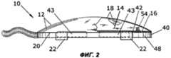
На фиг.2 изображен вид сбоку измерительного прибора совместно с устройством для улучшения видимости под водой согласно варианту осуществления изобретения.Figure 2 shows a side view of the measuring device in conjunction with a device for improving visibility under water according to a variant embodiment of the invention.
На фиг.3 изображен вид сбоку измерительного прибора совместно с устройством для улучшения видимости под водой согласно другому варианту осуществления изобретения.Figure 3 shows a side view of the measuring device in conjunction with a device for improving visibility under water according to another embodiment of the invention.
На фиг.4 изображен вид сбоку измерительного прибора совместно с устройством для улучшения видимости под водой, имеющим оптические линзы, согласно варианту осуществления изобретения.Figure 4 shows a side view of a measuring device in conjunction with a device for improving visibility under water having optical lenses according to an embodiment of the invention.
На фиг.5 изображен ныряльщик, который смотрит на измерительный прибор и имеет прикрепленное к запястью устройство для улучшения видимости под водой согласно варианту осуществления изобретения.Figure 5 shows a diver who is looking at a measuring device and has a device attached to his wrist to improve visibility under water according to an embodiment of the invention.
Осуществление изобретенияThe implementation of the invention
Последующее описание представляет наилучшие варианты реализации изобретения, существующие в настоящее время. Описание не должно пониматься в ограничивающем смысле, но лишь служит для целей иллюстрации основных принципов изобретения.The following description presents the best options for implementing the invention that currently exist. The description should not be understood in a limiting sense, but merely serves to illustrate the basic principles of the invention.
Как следует из фиг.1 и 2, устройство 10 для улучшения видимости под водой может представлять собой закрытый мешочек, оболочку или контейнер 12, образованный гибким, оптически прозрачным материалом, таким как пластмасса или другим пригодным материалом. Оболочка 12 заполнена текучей средой 14, прозрачной относительно обозреваемого пользователем объекта или устройства. Может использоваться оптически прозрачная вода и другие текучие среды, обладающие достаточной светопроницаемостью, чтобы обеспечить обозрение под водой.As follows from figures 1 and 2, the
Оболочка 12 имеет область 16 измерительного прибора и линзовую область 18 или область обозрения. Область 16 измерительного прибора прилегает к лицевому элементу 42 подводного устройства 40, которым может быть измерительный прибор, датчик, компас, компьютер или иное устройство. Лицевой элемент 42 представляет собой линзу измерительного прибора, стеклянную или пластмассовую крышку или другой смотровой элемент подводного устройства 40. Оболочка 12 снабжена ремешками 22, прикрепленными к периферийному краю 20 или другому подходящему месту на оболочке 12, с целью закрепления оболочки 12 на измерительном приборе, датчике, компасе, компьютере или ином подводном устройстве 40. Ремешки 22 могут быть снабжены креплением, таким как крючок, петля, защелка, хомут или подобное для соединения ремешков 22 между собой, так что они могут охватывать часть подводного устройства 40. Может быть предусмотрен запечатываемый проход 54 для текучей среды, расположенный в стенке оболочки 12, используемый для заполнения или удаления текучей среды 14. Устройство 10 для улучшения видимости под водой может поставляться пользователю без текучей среды 14, и пользователь заполняет оболочку 12 через проход 54. Для запечатывания или закрытия прохода 54 предусмотрена пробка или другое устройство.The
При расположении области 16 измерительного прибора напротив лицевого элемента 42 пользователь видит подводное устройство 40 или другой индикатор через линзовую область 18, текучую среду 14 и область 16 измерительного прибора. Обозрение подводного устройства возможно, когда ныряльщик находится под водой, и в особенности полезно в условиях темноты, мути, непрозрачной воды и т.д. Как хорошо видно на фиг.5, ныряльщик 50 может расположить подводное устройство 40, отображающее состояние баллона 44 с дыхательной смесью, или компас 46 напротив оптического стекла 52 маски. Устройство 10 для улучшения видимости под водой прижимается к оптическому стеклу 52 для вытеснения воды между лицевым элементом 42 и оптическим стеклом 52 маски. Теперь ныряльщик 50 способен видеть или считывать показания подводного устройства 10 через текучую среду 14.When the
На фиг.3 показано устройство 10 для улучшения видимости под водой, снабженное юбкой 24, сформованной таким образом, что она охватывает боковую кромку 48 подводного устройства 10, когда область 16 измерительного прибора прилегает к лицевому элементу 42. Предусмотрены крепежные элементы 26, соединенные с подводным устройством 40, используемые для прикрепления ремешков, лески 28 или подобных деталей, соединяемых с подводным устройством или юбкой 24. Леска может проходить через встроенную в юбку 24 трубку и таким образом использоваться для затягивания устройства 10 для улучшения видимости под водой на подводном устройстве 40.Figure 3 shows a
На фиг.4 показано, что устройство 10 для улучшения видимости под водой имеет карман 30 с закрытым концом 32, причем область 16 измерительного прибора может скользить вокруг подводного устройства 40 и охватывать его для удержания устройства 10 для улучшения видимости под водой на подводном устройстве 40. Предусмотрена леска 28 для закрытия открытого конца 34.Figure 4 shows that the
Линзовая область 18 имеет одну или более преломляющие линзы 36, встроенные в эту область или прикрепленные к ней, способствующие чтению или видению подводного устройства 40 ныряльщиком, нуждающимся в корректирующих оптических линзах. В устройстве 10 расположен источник 37 света. Источник 37 света имеет элемент электропитания, такой как батарейка, и выключатель 38. Выключатель 38 может представлять собой механический выключатель или выключатель, срабатывающий под действием давления. Последний включает источник 37 света, когда на устройство 10 для улучшения видимости под водой действует повышенное давление, например, когда это устройство 10 прижимается к оптическому стеклу маски.The
На фиг.1 и 2 показано, что оболочка 12 или закрытый контейнер может быть также сформирована путем прикрепления гибкого линзового элемента 18 к подводному устройству 10, например, к лицевому элементу 42. Линзовый элемент 18 может быть прикреплен к поверхности лицевого элемента 42 клеем или связующим, или механическим приспособлением, например, зажимным кольцом. В этом случае область 16 измерительного прибора не обязательно должна содержать текучую среду 14, поскольку закрытый контейнер может быть образован лицевым элементом 42 и линзовым элементом 18. При такой конструкции размер закрытого контейнера или оболочки 12 может быть выбран из условия соответствия форме лицевой стороны измерительного прибора 43.Figures 1 and 2 show that the
Несмотря на то что изобретение было проиллюстрировано и описано посредством предпочтительных примеров осуществления, специалисту должно быть понятно, что возможны изменения в его форме и деталях, не выходящие за пределы сущности и рамки изобретения.Although the invention has been illustrated and described by means of preferred embodiments, one skilled in the art will appreciate that changes in its form and details are possible without departing from the spirit and scope of the invention.
Claims (14)
Translated fromRussianApplications Claiming Priority (2)
| Application Number | Priority Date | Filing Date | Title |
|---|---|---|---|
| US11/012,749US7334909B2 (en) | 2004-12-15 | 2004-12-15 | Underwater visibility device |
| US11/012,749 | 2004-12-15 |
Publications (2)
| Publication Number | Publication Date |
|---|---|
| RU2007121902A RU2007121902A (en) | 2009-01-27 |
| RU2393511C2true RU2393511C2 (en) | 2010-06-27 |
Family
ID=36582523
Family Applications (1)
| Application Number | Title | Priority Date | Filing Date |
|---|---|---|---|
| RU2007121902/28ARU2393511C2 (en) | 2004-12-15 | 2005-12-12 | Device to improve subwater visibility |
Country Status (10)
| Country | Link |
|---|---|
| US (1) | US7334909B2 (en) |
| EP (1) | EP1824354B1 (en) |
| AU (1) | AU2005316682B2 (en) |
| CA (1) | CA2590910C (en) |
| EG (1) | EG25624A (en) |
| IL (1) | IL183725A (en) |
| MX (1) | MX2007006988A (en) |
| NZ (1) | NZ555711A (en) |
| RU (1) | RU2393511C2 (en) |
| WO (1) | WO2006065717A2 (en) |
Families Citing this family (5)
| Publication number | Priority date | Publication date | Assignee | Title |
|---|---|---|---|---|
| US8095233B1 (en)* | 2005-10-11 | 2012-01-10 | American Grid, Inc. | Interconnected premises equipment for energy management |
| USD565982S1 (en)* | 2006-09-06 | 2008-04-08 | Wayne Tracy Smith | Personal underwater signalling and emergency device for divers |
| GB2443022A (en)* | 2006-10-18 | 2008-04-23 | Advanced Diving Technology Ltd | Diving torch contained in a glove |
| CN103413573A (en)* | 2013-04-28 | 2013-11-27 | 张智 | Suspended indicator |
| US11268863B2 (en)* | 2018-07-04 | 2022-03-08 | Wika Alexander Wiegand Se & Co. Kg | Gauge with a flexible window cover |
Citations (4)
| Publication number | Priority date | Publication date | Assignee | Title |
|---|---|---|---|---|
| US3868853A (en)* | 1972-07-07 | 1975-03-04 | Carlo Alinari | Casing for liquid-filled depth gauge |
| GB2184562A (en)* | 1985-12-10 | 1987-06-24 | Joshua David Silver | Liquid or semi-solid lens or mirror with system for adjusting focal length |
| US5142299A (en)* | 1991-10-15 | 1992-08-25 | Braun Photo-Aquatic Systems | Hand held system for close-range underwater photography composing and focusing |
| US5764332A (en)* | 1991-08-28 | 1998-06-09 | Kranhouse; Jon | Diving mask with lenses and method of fabricating the same |
Family Cites Families (11)
| Publication number | Priority date | Publication date | Assignee | Title |
|---|---|---|---|---|
| US2632094A (en)* | 1949-02-07 | 1953-03-17 | Robert G Akerley | Flashlight having a sealed flexible casing |
| US2879381A (en)* | 1956-09-24 | 1959-03-24 | Robert G Coffey | Flashlights |
| DE1103172B (en)* | 1960-02-29 | 1961-03-23 | Ristau & Bergann | Aids for diving in turbid media |
| US3042796A (en)* | 1960-06-29 | 1962-07-03 | Forest Taber De | Flashlight assembly for underwater use |
| US3828611A (en)* | 1972-11-10 | 1974-08-13 | Farallon Ind | Portable underwater indicating instrument for divers |
| US3808621A (en)* | 1972-11-24 | 1974-05-07 | P French | Swimmer{40 s viewing float |
| GB1550513A (en)* | 1978-03-06 | 1979-08-15 | Swarbrick A | Method of and a device for underwater inspection of an objject submerged in dirty water |
| US4196623A (en)* | 1978-07-28 | 1980-04-08 | Carlo Alinari | Depth gauges |
| US4333348A (en)* | 1978-08-18 | 1982-06-08 | Alexander Wiegand Gmbh U. Co. | Liquid-filled pressure gauge |
| GB2075581A (en)* | 1980-05-03 | 1981-11-18 | Nuttall John Richard | Observation of objects in opaque liquids |
| US6460994B1 (en)* | 2000-08-24 | 2002-10-08 | Philip Nolan | Plano-convex lens system for underwater diving mask |
- 2004
- 2004-12-15USUS11/012,749patent/US7334909B2/ennot_activeExpired - Lifetime
- 2005
- 2005-12-12AUAU2005316682Apatent/AU2005316682B2/ennot_activeCeased
- 2005-12-12WOPCT/US2005/044833patent/WO2006065717A2/enactiveApplication Filing
- 2005-12-12MXMX2007006988Apatent/MX2007006988A/enactiveIP Right Grant
- 2005-12-12EPEP05853700.2Apatent/EP1824354B1/ennot_activeNot-in-force
- 2005-12-12RURU2007121902/28Apatent/RU2393511C2/ennot_activeIP Right Cessation
- 2005-12-12NZNZ555711Apatent/NZ555711A/ennot_activeIP Right Cessation
- 2005-12-12CACA2590910Apatent/CA2590910C/enactiveActive
- 2007
- 2007-06-06ILIL183725Apatent/IL183725A/ennot_activeIP Right Cessation
- 2007-06-11EGEGNA2007000570patent/EG25624A/enactive
Patent Citations (4)
| Publication number | Priority date | Publication date | Assignee | Title |
|---|---|---|---|---|
| US3868853A (en)* | 1972-07-07 | 1975-03-04 | Carlo Alinari | Casing for liquid-filled depth gauge |
| GB2184562A (en)* | 1985-12-10 | 1987-06-24 | Joshua David Silver | Liquid or semi-solid lens or mirror with system for adjusting focal length |
| US5764332A (en)* | 1991-08-28 | 1998-06-09 | Kranhouse; Jon | Diving mask with lenses and method of fabricating the same |
| US5142299A (en)* | 1991-10-15 | 1992-08-25 | Braun Photo-Aquatic Systems | Hand held system for close-range underwater photography composing and focusing |
Also Published As
| Publication number | Publication date |
|---|---|
| WO2006065717A3 (en) | 2007-02-08 |
| EP1824354A4 (en) | 2012-03-14 |
| EP1824354A2 (en) | 2007-08-29 |
| EP1824354B1 (en) | 2015-07-15 |
| NZ555711A (en) | 2011-04-29 |
| MX2007006988A (en) | 2007-11-15 |
| CA2590910C (en) | 2014-07-08 |
| IL183725A (en) | 2011-07-31 |
| CA2590910A1 (en) | 2006-06-22 |
| AU2005316682A1 (en) | 2006-06-22 |
| IL183725A0 (en) | 2007-09-20 |
| AU2005316682B2 (en) | 2012-05-24 |
| US20060124483A1 (en) | 2006-06-15 |
| EG25624A (en) | 2012-04-03 |
| RU2007121902A (en) | 2009-01-27 |
| US7334909B2 (en) | 2008-02-26 |
| WO2006065717A2 (en) | 2006-06-22 |
Similar Documents
| Publication | Publication Date | Title |
|---|---|---|
| US4772986A (en) | Illuminating device | |
| US3712714A (en) | Information display for diver{40 s face mask | |
| US5361169A (en) | Diver's mirror | |
| US6868360B1 (en) | Small head-mounted compass system with optical display | |
| US5301668A (en) | Field of view underwater diving computer monitoring and display system | |
| US5694261A (en) | Diver's mirror | |
| RU2393511C2 (en) | Device to improve subwater visibility | |
| US4809550A (en) | Digital diving meter | |
| CN103129722B (en) | Divemask and diving equipment | |
| CA2376188A1 (en) | Magnifying contact lens storage unit | |
| US6837240B1 (en) | Display system upgrade for a full face mask | |
| US6694911B1 (en) | Enhanced display- underwater combat swim board | |
| CN106510080A (en) | Underwater ultrasonic detection helmet | |
| US5205449A (en) | Forearm gauge and equipment holder for scuba divers | |
| CN217227878U (en) | Diving equipment convenient to observe data | |
| FI91686B (en) | Instrument | |
| US20050237386A1 (en) | Underwater mask camera | |
| US6039446A (en) | Face shield, incorporating a wrist watch display | |
| KR102791957B1 (en) | Underwater structure diagnostic imaging device | |
| RU79274U1 (en) | WATER CAPILLARY DEPTH METER | |
| RU2368927C2 (en) | Container for video-photo shooting | |
| US20030076676A1 (en) | Diver's mask and lighting assembly | |
| CN209803326U (en) | Underwater camera and measuring device | |
| KR200359424Y1 (en) | Camera waterproof case. | |
| US20180275618A1 (en) | Information apparatus and sensor attaching tool |
Legal Events
| Date | Code | Title | Description |
|---|---|---|---|
| MM4A | The patent is invalid due to non-payment of fees | Effective date:20121213 | |
| NF4A | Reinstatement of patent | Effective date:20130927 | |
| MM4A | The patent is invalid due to non-payment of fees | Effective date:20191213 |