RU2392975C2 - Air-valve membrane pump - Google Patents
Air-valve membrane pumpDownload PDFInfo
- Publication number
- RU2392975C2 RU2392975C2RU2007112933/14ARU2007112933ARU2392975C2RU 2392975 C2RU2392975 C2RU 2392975C2RU 2007112933/14 ARU2007112933/14 ARU 2007112933/14ARU 2007112933 ARU2007112933 ARU 2007112933ARU 2392975 C2RU2392975 C2RU 2392975C2
- Authority
- RU
- Russia
- Prior art keywords
- air
- membrane
- suction pump
- vacuum
- pump according
- Prior art date
Links
- 239000012528membraneSubstances0.000titleclaimsabstractdescription119
- 125000004122cyclic groupChemical group0.000claimsabstract2
- 238000000034methodMethods0.000claimsdescription9
- 229920001296polysiloxanePolymers0.000claimsdescription5
- 238000011010flushing procedureMethods0.000claimsdescription2
- 239000003814drugSubstances0.000abstract1
- 238000004659sterilization and disinfectionMethods0.000abstract1
- 239000000126substanceSubstances0.000abstract1
- 238000007789sealingMethods0.000description12
- 235000013336milkNutrition0.000description11
- 239000008267milkSubstances0.000description11
- 210000004080milkAnatomy0.000description11
- 235000020256human milkNutrition0.000description5
- 239000000463materialSubstances0.000description5
- 210000004251human milkAnatomy0.000description4
- 239000007788liquidSubstances0.000description4
- 238000004519manufacturing processMethods0.000description4
- 210000000481breastAnatomy0.000description3
- 210000000038chestAnatomy0.000description3
- 239000012530fluidSubstances0.000description3
- 230000033764rhythmic processEffects0.000description3
- 238000000926separation methodMethods0.000description3
- 241000252254CatostomidaeSpecies0.000description2
- 238000004140cleaningMethods0.000description2
- 238000004891communicationMethods0.000description2
- 238000010276constructionMethods0.000description2
- 238000009434installationMethods0.000description2
- 210000002445nippleAnatomy0.000description2
- 125000006850spacer groupChemical group0.000description2
- 230000008719thickeningEffects0.000description2
- 210000000115thoracic cavityAnatomy0.000description2
- 229930040373ParaformaldehydeNatural products0.000description1
- 238000010521absorption reactionMethods0.000description1
- 230000000712assemblyEffects0.000description1
- 238000000429assemblyMethods0.000description1
- 230000007423decreaseEffects0.000description1
- 230000003670easy-to-cleanEffects0.000description1
- 230000008030eliminationEffects0.000description1
- 238000003379elimination reactionMethods0.000description1
- 238000009413insulationMethods0.000description1
- 238000012423maintenanceMethods0.000description1
- 230000007257malfunctionEffects0.000description1
- -1polyoxymethylenePolymers0.000description1
- 229920006324polyoxymethylenePolymers0.000description1
- 238000005086pumpingMethods0.000description1
- 230000000638stimulationEffects0.000description1
- XLYOFNOQVPJJNP-UHFFFAOYSA-NwaterSubstancesOXLYOFNOQVPJJNP-UHFFFAOYSA-N0.000description1
Images


Classifications
- A—HUMAN NECESSITIES
- A61—MEDICAL OR VETERINARY SCIENCE; HYGIENE
- A61M—DEVICES FOR INTRODUCING MEDIA INTO, OR ONTO, THE BODY; DEVICES FOR TRANSDUCING BODY MEDIA OR FOR TAKING MEDIA FROM THE BODY; DEVICES FOR PRODUCING OR ENDING SLEEP OR STUPOR
- A61M1/00—Suction or pumping devices for medical purposes; Devices for carrying-off, for treatment of, or for carrying-over, body-liquids; Drainage systems
- A61M1/06—Milking pumps
- A61M1/062—Pump accessories
- A61M1/064—Suction cups
- A61M1/066—Inserts therefor
- A—HUMAN NECESSITIES
- A61—MEDICAL OR VETERINARY SCIENCE; HYGIENE
- A61M—DEVICES FOR INTRODUCING MEDIA INTO, OR ONTO, THE BODY; DEVICES FOR TRANSDUCING BODY MEDIA OR FOR TAKING MEDIA FROM THE BODY; DEVICES FOR PRODUCING OR ENDING SLEEP OR STUPOR
- A61M1/00—Suction or pumping devices for medical purposes; Devices for carrying-off, for treatment of, or for carrying-over, body-liquids; Drainage systems
- A61M1/80—Suction pumps
- A61M1/82—Membrane pumps, e.g. bulbs
- F—MECHANICAL ENGINEERING; LIGHTING; HEATING; WEAPONS; BLASTING
- F04—POSITIVE - DISPLACEMENT MACHINES FOR LIQUIDS; PUMPS FOR LIQUIDS OR ELASTIC FLUIDS
- F04B—POSITIVE-DISPLACEMENT MACHINES FOR LIQUIDS; PUMPS
- F04B43/00—Machines, pumps, or pumping installations having flexible working members
- F—MECHANICAL ENGINEERING; LIGHTING; HEATING; WEAPONS; BLASTING
- F04—POSITIVE - DISPLACEMENT MACHINES FOR LIQUIDS; PUMPS FOR LIQUIDS OR ELASTIC FLUIDS
- F04B—POSITIVE-DISPLACEMENT MACHINES FOR LIQUIDS; PUMPS
- F04B43/00—Machines, pumps, or pumping installations having flexible working members
- F04B43/0009—Special features
- F04B43/0054—Special features particularities of the flexible members
- F—MECHANICAL ENGINEERING; LIGHTING; HEATING; WEAPONS; BLASTING
- F04—POSITIVE - DISPLACEMENT MACHINES FOR LIQUIDS; PUMPS FOR LIQUIDS OR ELASTIC FLUIDS
- F04B—POSITIVE-DISPLACEMENT MACHINES FOR LIQUIDS; PUMPS
- F04B45/00—Pumps or pumping installations having flexible working members and specially adapted for elastic fluids
- F04B45/04—Pumps or pumping installations having flexible working members and specially adapted for elastic fluids having plate-like flexible members, e.g. diaphragms
- F04B45/047—Pumps having electric drive
- F—MECHANICAL ENGINEERING; LIGHTING; HEATING; WEAPONS; BLASTING
- F04—POSITIVE - DISPLACEMENT MACHINES FOR LIQUIDS; PUMPS FOR LIQUIDS OR ELASTIC FLUIDS
- F04B—POSITIVE-DISPLACEMENT MACHINES FOR LIQUIDS; PUMPS
- F04B49/00—Control, e.g. of pump delivery, or pump pressure of, or safety measures for, machines, pumps, or pumping installations, not otherwise provided for, or of interest apart from, groups F04B1/00 - F04B47/00
- F04B49/02—Stopping, starting, unloading or idling control
- F04B49/03—Stopping, starting, unloading or idling control by means of valves
- F—MECHANICAL ENGINEERING; LIGHTING; HEATING; WEAPONS; BLASTING
- F04—POSITIVE - DISPLACEMENT MACHINES FOR LIQUIDS; PUMPS FOR LIQUIDS OR ELASTIC FLUIDS
- F04B—POSITIVE-DISPLACEMENT MACHINES FOR LIQUIDS; PUMPS
- F04B49/00—Control, e.g. of pump delivery, or pump pressure of, or safety measures for, machines, pumps, or pumping installations, not otherwise provided for, or of interest apart from, groups F04B1/00 - F04B47/00
- F04B49/10—Other safety measures
- A—HUMAN NECESSITIES
- A61—MEDICAL OR VETERINARY SCIENCE; HYGIENE
- A61M—DEVICES FOR INTRODUCING MEDIA INTO, OR ONTO, THE BODY; DEVICES FOR TRANSDUCING BODY MEDIA OR FOR TAKING MEDIA FROM THE BODY; DEVICES FOR PRODUCING OR ENDING SLEEP OR STUPOR
- A61M1/00—Suction or pumping devices for medical purposes; Devices for carrying-off, for treatment of, or for carrying-over, body-liquids; Drainage systems
- A61M1/80—Suction pumps
- A61M1/802—Suction pumps by vacuum created above a liquid flowing from a closed container
- A—HUMAN NECESSITIES
- A61—MEDICAL OR VETERINARY SCIENCE; HYGIENE
- A61M—DEVICES FOR INTRODUCING MEDIA INTO, OR ONTO, THE BODY; DEVICES FOR TRANSDUCING BODY MEDIA OR FOR TAKING MEDIA FROM THE BODY; DEVICES FOR PRODUCING OR ENDING SLEEP OR STUPOR
- A61M2205/00—General characteristics of the apparatus
- A61M2205/33—Controlling, regulating or measuring
- A61M2205/3331—Pressure; Flow
- A61M2205/3337—Controlling, regulating pressure or flow by means of a valve by-passing a pump
- A—HUMAN NECESSITIES
- A61—MEDICAL OR VETERINARY SCIENCE; HYGIENE
- A61M—DEVICES FOR INTRODUCING MEDIA INTO, OR ONTO, THE BODY; DEVICES FOR TRANSDUCING BODY MEDIA OR FOR TAKING MEDIA FROM THE BODY; DEVICES FOR PRODUCING OR ENDING SLEEP OR STUPOR
- A61M2205/00—General characteristics of the apparatus
- A61M2205/42—Reducing noise
- A—HUMAN NECESSITIES
- A61—MEDICAL OR VETERINARY SCIENCE; HYGIENE
- A61M—DEVICES FOR INTRODUCING MEDIA INTO, OR ONTO, THE BODY; DEVICES FOR TRANSDUCING BODY MEDIA OR FOR TAKING MEDIA FROM THE BODY; DEVICES FOR PRODUCING OR ENDING SLEEP OR STUPOR
- A61M2205/00—General characteristics of the apparatus
- A61M2205/82—Internal energy supply devices
- A61M2205/8206—Internal energy supply devices battery-operated
- F—MECHANICAL ENGINEERING; LIGHTING; HEATING; WEAPONS; BLASTING
- F16—ENGINEERING ELEMENTS AND UNITS; GENERAL MEASURES FOR PRODUCING AND MAINTAINING EFFECTIVE FUNCTIONING OF MACHINES OR INSTALLATIONS; THERMAL INSULATION IN GENERAL
- F16K—VALVES; TAPS; COCKS; ACTUATING-FLOATS; DEVICES FOR VENTING OR AERATING
- F16K31/00—Actuating devices; Operating means; Releasing devices
- F16K31/02—Actuating devices; Operating means; Releasing devices electric; magnetic
- F16K31/06—Actuating devices; Operating means; Releasing devices electric; magnetic using a magnet, e.g. diaphragm valves, cutting off by means of a liquid
- F16K31/0644—One-way valve
- F16K31/0672—One-way valve the valve member being a diaphragm
Landscapes
- Engineering & Computer Science (AREA)
- Health & Medical Sciences (AREA)
- Heart & Thoracic Surgery (AREA)
- Mechanical Engineering (AREA)
- General Engineering & Computer Science (AREA)
- Life Sciences & Earth Sciences (AREA)
- Veterinary Medicine (AREA)
- Anesthesiology (AREA)
- Biomedical Technology (AREA)
- Hematology (AREA)
- Vascular Medicine (AREA)
- Animal Behavior & Ethology (AREA)
- General Health & Medical Sciences (AREA)
- Public Health (AREA)
- Pediatric Medicine (AREA)
- Reciprocating Pumps (AREA)
- External Artificial Organs (AREA)
- Separation Using Semi-Permeable Membranes (AREA)
- Massaging Devices (AREA)
- Valves And Accessory Devices For Braking Systems (AREA)
- Structures Of Non-Positive Displacement Pumps (AREA)
- Details Of Reciprocating Pumps (AREA)
- Infusion, Injection, And Reservoir Apparatuses (AREA)
Abstract
Description
Translated fromRussianОбласть техники, к которой относится изобретениеFIELD OF THE INVENTION
Настоящее изобретение относится к способу управления работой отсасывающего насоса с воздушным клапаном согласно ограничительной части пункта 1, отсасывающему насосу с воздушным клапаном согласно ограничительной части пунктов 5 и 19 и отсасывающему насосу с предохранительным клапаном согласно ограничительной части пункта 28.The present invention relates to a method for controlling the operation of a suction pump with an air valve according to the restrictive part of
Уровень техникиState of the art
Известны отсасывающие насосы, пригодные для широкого спектра областей применения. Однако предпочтительно они используются в устройствах молокоотсасывателей для отсасывания грудного молока или как дренирующие отсасыватели для физиологических жидкостей.Suction pumps are known for a wide range of applications. However, they are preferably used in breast milk suction devices for sucking breast milk or as draining suction pumps for physiological fluids.
Существуют отсасывающие насосы в закрытых системах, которые постоянно прогоняют тот же самый воздух через насосную камеру. Однако также известны и открытые насосные системы с воздушным клапаном, который может открываться циклично с помощью электромагнита.There are suction pumps in closed systems that constantly drive the same air through the pump chamber. However, open pump systems with an air valve, which can be opened cyclically by an electromagnet, are also known.
Требования, предъявляемые к отсасывающим насосам, особенно, если они используются как молокоотсасыватели, достаточно высоки. Они должны иметь максимальную мощность, однако в то же время быть относительно небольшими. В особенности при использовании в качестве молокоотсасывателей они должны работать при минимальном обслуживании и быть простыми для чистки.The requirements for suction pumps, especially if they are used as milk suckers, are quite high. They should have maximum power, but at the same time be relatively small. Especially when used as milk suckers, they should work with minimal maintenance and be easy to clean.
Раскрытие изобретенияDisclosure of invention
Задачей настоящего изобретения является создание способа работы отсасывающего насоса с воздушным клапаном, а также создание отсасывающего насоса с воздушным клапаном, причем в обоих случаях предусматривается конструкция насоса с минимально возможными габаритами, в то же время осуществляющего короткие насосные циклы.The objective of the present invention is to provide a method of operating a suction pump with an air valve, as well as creating a suction pump with an air valve, and in both cases the design of the pump with the smallest possible dimensions, at the same time performing short pump cycles, is provided.
Данная задача достигается предложенным способом и насосом, имеющим признаки пунктов 1 и 5, соответственно.This task is achieved by the proposed method and the pump having the signs of
Согласно способу по настоящему изобретению воздушный элемент, закрывающий воздушное отверстие воздушного клапана, сначала приподнимается только частично. Таким образом, требуется меньшее усилие, чем если бы все воздушное отверстие было открыто в один этап.According to the method of the present invention, the air element covering the air hole of the air valve is first only partially lifted. Thus, less effort is required than if the entire air hole was opened in one step.
Приводные средства, в особенности для подъема воздушного элемента, поэтому могут быть менее мощными и, следовательно, иметь меньшие размеры. Если в качестве такого средства используется электромагнит, то может применяться его тип, имеющий относительно низкую мощность. Это объясняется тем, что во время притягивания или подъема воздушного элемента электромагнит сначала может развивать меньшее усилие, чем в конце этой операции. Этой первоначально имеющейся небольшой силы, однако, достаточно для открытия относительно небольшого отверстия. Поэтому возможно использование относительно небольшого и поэтому также недорогого электромагнита. Более того, воздушное отверстие может быть выполнено относительно большим. Это обеспечивает быструю ликвидацию вакуума и, следовательно, желаемую функциональность насоса.The drive means, in particular for lifting the air element, can therefore be less powerful and therefore smaller. If an electromagnet is used as such a tool, then a type having a relatively low power may be used. This is because during the pulling or lifting of the air element, the electromagnet can initially develop less force than at the end of this operation. This initially small force, however, is sufficient to open a relatively small hole. Therefore, it is possible to use a relatively small and therefore also inexpensive electromagnet. Moreover, the air hole can be made relatively large. This ensures quick elimination of the vacuum and, therefore, the desired functionality of the pump.
Насос легко достигает скорости 120 циклов в минуту. Однако он также может работать оптимально со скоростью 50-72 циклов в минуту. Первая скорость особенно пригодна для стимуляции, вторая - для сцеживания грудного молока.The pump easily reaches a speed of 120 cycles per minute. However, it can also operate optimally at a speed of 50-72 cycles per minute. The first speed is especially suitable for stimulation, the second for expressing breast milk.
В предпочтительном варианте способа согласно изобретению воздушный элемент сначала снимают с краевой области воздушного отверстия. Требуется минимальное усилие, если эта краевая область совпадает с углом воздушного элемента.In a preferred embodiment of the method according to the invention, the air element is first removed from the edge region of the air hole. Minimal effort is required if this edge region coincides with the angle of the air element.
Воздушный элемент предпочтительно является мембраной. Поднятие ее краевой области облегчается, если поднимаемая краевая область имеет меньшую толщину, чем остальная часть мембраны. Воздушное отверстие предпочтительно является многоугольным, в особенности прямоугольным или треугольным. Мембрана также предпочтительно является многоугольной, предпочтительно прямоугольной или треугольной.The air element is preferably a membrane. Raising its edge region is facilitated if the elevated edge region is thinner than the rest of the membrane. The air hole is preferably polygonal, especially rectangular or triangular. The membrane is also preferably polygonal, preferably rectangular or triangular.
Для облегчения поднятия мембраны к ней может быть прикреплен или на ней может быть выполнен, заодно с мембраной, соединительный штифт, который соединен с якорем подъемного магнита. Этот соединительный штифт предпочтительно расположен в краевой области мембраны, закрывающей воздушное отверстие. Однако мембрана также может иметь приподнятый фланец, в этом случае соединительный штифт находится не над воздушным отверстием, а на указанном фланце.To facilitate the lifting of the membrane, a connecting pin that can be connected to the anchor of the lifting magnet can be attached to it or on it, at the same time as the membrane. This connecting pin is preferably located in the edge region of the membrane covering the air hole. However, the membrane may also have a raised flange, in this case, the connecting pin is not located above the air hole, but on the specified flange.
Если соединительный штифт выполнен с возможностью смещения относительно мембраны, то это позволяет компенсировать любые производственные или сборочные допуски. Могут быть компенсированы также ошибки угла установки электромагнита. Были достигнуты хорошие результаты при использовании соединительного штифта, выполненного заодно с изготовленной из силикона мембраной и имеющего достаточную жесткость благодаря соответствующему утолщению материала. Штифт может быть установлен на мембране шарнирным способом. Однако в простом воплощении эластичность материала соединительного штифта является достаточной для обеспечения его подвижности в точке прикрепления.If the connecting pin is movable relative to the membrane, then this makes it possible to compensate for any manufacturing or assembly tolerances. Errors in the angle of installation of the electromagnet can also be compensated. Good results were achieved when using a connecting pin, made at the same time with a membrane made of silicone and having sufficient rigidity due to the corresponding thickening of the material. The pin can be mounted on the membrane articulated. However, in a simple embodiment, the elasticity of the material of the connecting pin is sufficient to ensure its mobility at the attachment point.
В другом варианте воздушный элемент имеет первый вспомогательный блок и второй вспомогательный блок. Первый вспомогательный блок закрывает воздушное отверстие лишь частично, так как он имеет воздушный канал, связывающий воздушное отверстие с внешней средой. Первый вспомогательный блок, имеющий воздушный канал, может быть закрыт вторым вспомогательным блоком. Во время впуска воздуха вначале поднимается только первый вспомогательный блок, или этот блок отодвигается от воздушного канала, так что открывается только часть воздушного отверстия. Затем второй вспомогательный блок также может быть отодвинут для открытия всего воздушного отверстия. На этой второй ступени второй вспомогательный блок предпочтительно приводится в действие совместно с первым вспомогательным блоком.In another embodiment, the air element has a first auxiliary unit and a second auxiliary unit. The first auxiliary unit only partially closes the air hole, since it has an air channel connecting the air hole with the external environment. The first auxiliary unit having an air channel may be closed by the second auxiliary unit. During the air inlet, only the first auxiliary unit first rises, or this unit moves away from the air channel, so that only part of the air hole is opened. Then, the second auxiliary unit can also be moved away to open the entire air hole. In this second stage, the second auxiliary unit is preferably driven in conjunction with the first auxiliary unit.
По сравнению с этим вариантом первый вариант, в котором воздушная мембрана может приводиться в действие на краевой области, имеет преимущество, заключающееся в предотвращении утечек, таким образом, в особенности при использовании в качестве молокоотсасывателя, обеспечивает отсутствие протечки всосанного молока.Compared to this embodiment, the first embodiment, in which the air membrane can be actuated at the edge region, has the advantage of preventing leakage, thus, especially when used as a milk sucker, ensures that the sucked milk does not leak.
Дальнейшим преимуществом вышеупомянутых вариантов, особенно в отношении использования мембраны, является отсутствие необходимости в пружинах и поэтому может быть уменьшено число требуемых отдельных деталей. Поскольку не требуется установка пружины, уменьшается работа, связанная со сборкой насоса.A further advantage of the above options, especially with regard to the use of the membrane, is the absence of need for springs and therefore the number of individual parts required can be reduced. Since no spring installation is required, the work associated with assembling the pump is reduced.
Дальнейшей задачей настоящего изобретения является создание отсасывающего насоса, который может быть собран наиболее простым образом.A further object of the present invention is to provide a suction pump, which can be assembled in the simplest manner.
Данная задача достигается в отсасывающем насосе, имеющем признаки пункта 19.This task is achieved in a suction pump having the characteristics of paragraph 19.
Отсасывающий насос согласно изобретению имеет воздушный клапан с воздушной мембраной, причем воздушная мембрана выполнена заодно с вакуумной мембраной, используемой для создания вакуума, в виде единой мембранной пластины.The suction pump according to the invention has an air valve with an air membrane, the air membrane being integral with the vacuum membrane used to create the vacuum in the form of a single membrane plate.
Размещение воздушного клапана и вакуумной мембраны на одной пластине означает удешевление производства и упрощение сборки.Placing an air valve and a vacuum membrane on one plate means cheaper manufacturing and easier assembly.
В предпочтительном варианте насос содержит верхнюю часть корпуса, среднюю часть корпуса и нижнюю часть корпуса, причем мембранная пластина и пластина клапана размещены между этими частями корпуса. Такое разделение означает, что несколько деталей могут быть сформированы на той же самой конструктивной части. В особенности, вакуумная мембрана, необходимая для создания вакуума, и воздушная мембрана, необходимая для быстрой ликвидации вакуума, могут быть выполнены заодно на той же самой конструктивной части. Контрольные заслонки и заслонки клапана также могут быть сформированы в одно целое на одной и той же конструктивной части. Электродвигатель и электромагнит могут быть установлены в одной и той же части корпуса. Путем разделения насоса на несколько уровней, предпочтительно пять уровней, число отдельных деталей может быть сведено к минимуму без необходимости отказа от сложной конструкции насосного блока. Это не только уменьшает внешние габариты насосного блока, но также минимизирует производственные и сборочные затраты.In a preferred embodiment, the pump comprises an upper part of the housing, a middle part of the housing and a lower part of the housing, the membrane plate and the valve plate being placed between these parts of the housing. This separation means that several parts can be formed on the same structural part. In particular, the vacuum membrane necessary to create a vacuum, and the air membrane necessary to quickly eliminate the vacuum, can be performed at the same time on the same structural part. The control flaps and valve flaps can also be formed integrally on the same structural part. An electric motor and an electromagnet can be installed in the same part of the housing. By dividing the pump into several levels, preferably five levels, the number of individual parts can be minimized without having to abandon the complex design of the pump unit. This not only reduces the external dimensions of the pump unit, but also minimizes production and assembly costs.
Дальнейшим преимуществом данной модульной конструкции с несколькими уровнями является то, что насос может быть очищен простой промывкой, без необходимости разборки на детали. Благодаря ведущему наружу выпуску отпадает необходимость в губке. Такие известные из уровня техники губки используются для впитывания молока, всосанного насосом, и для уменьшения шума. Однако они занимают место в насосе и могут создавать неприятный запах.A further advantage of this multi-level modular design is that the pump can be cleaned by simple flushing, without having to disassemble it into parts. Thanks to the outward leading outlet, there is no need for a sponge. Such sponges known in the art are used to absorb milk sucked by a pump and to reduce noise. However, they take up space in the pump and can create an unpleasant odor.
Данная модульная конструкция также может быть использована в насосе, не имеющем вышеупомянутого воздушного клапана согласно изобретению.This modular design can also be used in a pump that does not have the aforementioned air valve according to the invention.
Дальнейшей задачей изобретения является создание отсасывающего насоса, который имеет предохранительный клапан и не может быть инактивирован жидкостью, в особенности молоком, которая всосана в насос и накопилась в нем.A further object of the invention is to provide a suction pump that has a safety valve and cannot be inactivated by a liquid, especially milk, which is sucked into the pump and accumulated in it.
Данная задача достигается в отсасывающем насосе, имеющем признаки пункта 28.This task is achieved in a suction pump having the characteristics of paragraph 28.
Отсасывающий насос согласно настоящему изобретению имеет предохранительный клапан с первой ступенью, открывающейся при первом значении пониженного давления, и со второй ступенью, открывающейся при втором значении пониженного давления. Первое значение меньше второго.The suction pump according to the present invention has a safety valve with a first stage opening at a first reduced pressure value and with a second stage opening at a second reduced pressure value. The first value is less than the second.
Данная двухступенчатая конструкция предохранительного клапана препятствует достижению молоком второй ступени. Поскольку первая ступень открывается даже в случае очень небольшого отклонения от идеального значения пониженного давления, она также откроется в случае засорения, если значение пониженного давления находится на более высоком уровне, иными словами в чрезвычайной ситуации. Вторая ступень не позволяет всему предохранительному клапану открыться при небольшом отклонении от идеального значения, но она надежно открывается при чрезвычайной ситуации.This two-stage safety valve design prevents milk from reaching the second stage. Since the first stage opens even in the case of a very small deviation from the ideal value of the reduced pressure, it will also open in the event of clogging, if the value of the reduced pressure is at a higher level, in other words in an emergency. The second stage does not allow the entire safety valve to open with a slight deviation from the ideal value, but it opens reliably in an emergency.
Данный двухступенчатый предохранительный клапан может также использоваться в насосе, не имеющем вышеупомянутого воздушного клапана согласно настоящему изобретению, а также модульной конструкции.This two-stage safety valve can also be used in a pump that does not have the aforementioned air valve according to the present invention, as well as a modular design.
Отсасывающий насос согласно настоящему изобретению может, таким образом, уменьшать степень вакуума за относительно короткое время и без большого усилия. Насос согласно настоящему изобретению пригоден для широкого спектра применений. Он особенно пригоден как молокоотсасыватель для отсасывания грудного молока и как дренажный насос для физиологических жидкостей. Насосный блок согласно настоящему изобретению особенно пригоден для использования в переносном молокоотсасывателе, как это описано в еще не опубликованной заявке РСТ/СН2004/000061.The suction pump according to the present invention can thus reduce the degree of vacuum in a relatively short time and without much effort. The pump according to the present invention is suitable for a wide range of applications. It is particularly suitable as a breast pump for sucking breast milk and as a drainage pump for physiological fluids. The pump unit according to the present invention is particularly suitable for use in a portable milk sucker, as described in the unpublished application PCT / CH2004 / 000061.
Дальнейшие предпочтительные варианты охарактеризованы в прилагаемой формуле изобретения.Further preferred embodiments are described in the appended claims.
Краткое описание чертежейBrief Description of the Drawings
Объект изобретения описан ниже на основе предпочтительных иллюстративных вариантов, изображенных на прилагаемых чертежах, где:An object of the invention is described below on the basis of preferred illustrative options depicted in the accompanying drawings, where:
Фиг.1 - общий вид отсасывающего насоса согласно настоящему изобретению, без внешнего кожуха;Figure 1 - General view of the suction pump according to the present invention, without an outer casing;
Фиг.2 - вид снизу отсасывающего насоса, изображенного на Фиг.1;Figure 2 is a bottom view of the suction pump shown in Figure 1;
Фиг.3 - продольное сечение отсасывающего насоса по Фиг.1;Figure 3 is a longitudinal section of the suction pump of Figure 1;
Фиг.4 - объемное изображение с пространственным разделением деталей отсасывающего насоса, изображенного на Фиг.1;Figure 4 - volumetric image with a spatial separation of the parts of the suction pump shown in Figure 1;
Фиг.5 - общий вид нижней части корпуса отсасывающего насоса, изображенного на Фиг.1;Figure 5 is a General view of the lower part of the housing of the suction pump shown in Figure 1;
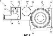
Фиг.6 - вид сверху мембранной пластины отсасывающего насоса, изображенного на Фиг.1;Fig.6 is a top view of the membrane plate of the suction pump shown in Fig.1;
Фиг.7 - продольное сечение мембранной пластины, изображенной на Фиг.6;Fig.7 is a longitudinal section of the membrane plate depicted in Fig.6;
Фиг.8 - увеличенная часть мембранной пластины, изображенной на Фиг.7;Fig.8 is an enlarged part of the membrane plate depicted in Fig.7;
Фиг.9 - увеличенный вид участка верхней части корпуса;Fig.9 is an enlarged view of a portion of the upper part of the housing;
Фиг.10 - вид сверху мембранной пластины отсасывающего насоса согласно второму варианту;Figure 10 is a top view of the membrane plate of the suction pump according to the second embodiment;
Фиг.11 - продольное сечение мембранной пластины по Фиг.10;11 is a longitudinal section of a membrane plate of FIG. 10;
Фиг.12 - увеличенная деталь мембранной пластины по Фиг.11;Fig.12 is an enlarged detail of the membrane plate of Fig.11;
Фиг.13 - продольное сечение воздушного узла согласно третьему варианту настоящего изобретения.13 is a longitudinal section of an air unit according to a third embodiment of the present invention.
Осуществление изобретенияThe implementation of the invention
Фиг.1 показывает отсасывающий насос согласно настоящему изобретению, который пригоден в особенности для устройства молокоотсасывателя для отсасывания человеческого грудного молока. Однако насос также пригоден для других применений, например в качестве дренажных насосов для всасывания физиологических жидкостей.Figure 1 shows a suction pump according to the present invention, which is particularly suitable for a breast pump for sucking human breast milk. However, the pump is also suitable for other applications, for example, as drainage pumps for the absorption of physiological fluids.
Показан только непосредственно насосный блок. Этот блок обычно помещен во внешний кожух. Чертеж не показывает внешний кожух, а также электронику, необходимую для приведения в действие насоса, и любые средства энергопитания, например аккумулятор или батарею.Only the pump unit is shown directly. This block is usually placed in an outer casing. The drawing does not show the outer casing, as well as the electronics necessary to drive the pump, and any means of power supply, such as a battery or battery.
Структура насоса чрезвычайно компактна. Один из его самых больших узлов - электродвигатель 1. Насос также имеет верхнюю часть 2 корпуса, среднюю часть 4 корпуса и нижнюю часть 6 корпуса, которые могут быть соединены разъемным креплением. Также предусмотрена приставка 7, являющаяся компонентом этих частей корпуса или, как в данном случае, прикрепляемая к ним разъемным образом.The structure of the pump is extremely compact. One of its largest assemblies is
На приставке 7 имеется, по меньшей мере, один присоединительный элемент 70 грудной насадки, к которому может быть присоединена соединительная трубка к грудной насадке, накладываемой на сосок. Приставка 7 также содержит выпуск 71. Этот выпуск 71 выходит из внешнего кожуха. Кроме того, имеется воздушный присоединительный элемент 72 в виде канала, выходящий из внешнего кожуха, и распорки 73. Распорки 73 соединяют насосный блок с внешним кожухом с предотвращением вибрации и обеспечением достаточной звукоизоляции.On the prefix 7, there is at least one connecting
На Фиг.2 видно, каким образом отдельные присоединительные элементы 70, 71, 72 соединены отдельными каналами с отдельными областями насоса.Figure 2 shows how the
Продольное сечение насоса на Фиг.3, где отсутствует двигатель 1, показывает, что насос, несмотря на его компактную конструкцию, разделен на три ясно различимые функциональные зоны: насосный узел Р, атмосферный узел V и расположенный между ними предохранительный узел S. Устройство насоса лучше всего показано на общем виде на Фиг.3 и 4.The longitudinal section of the pump in FIG. 3, where
Насосный узел Р содержит вакуумную мембрану 31 и впускную и выпускную контрольные заслонки 51, 52, которые, вместе с впускным и выпускным отверстиями 62, 63 и с отверстием 43' насосной камеры, создают сообщение между насосной камерой 43 и вакуумным каналом 69. Вакуумная мембрана 31 соединена с приводным валом 10 электродвигателя 1 посредством соединительной тяги 11, втулки 12, например, подшипника, и эксцентрика 13 и с помощью двигателя 1 может подниматься и опускаться в соответствии с заранее заданным ритмом или насосной функциональной кривой, или в соответствии с ритмом или функциональной кривой, которые могут быть свободно выбраны через систему управления.The pump assembly P comprises a
Атмосферный узел V содержит воздушный клапан с воздушной мембраной 32, а также воздушное отверстие, которое может герметично закрываться последней и имеет форму опоры 44 воздушной мембраны. Камера 44', в которой находится опора 44 воздушной мембраны, соединена воздушным присоединительным элементом 45 с воздушным каналом 72. Опора 44 воздушной мембраны открыта снизу, иными словами со стороны, противоположной воздушной мембране 32, и примыкает к первому воздушному отверстию 54 пластины 5 клапана и ко второму воздушному отверстию 67 нижней части 6 корпуса. Второе воздушное отверстие 67 сообщается через вакуумный канал 69 с камерой 68 предохранительного клапана и с впускным отверстием 62.The atmospheric assembly V comprises an air valve with an
Воздушная мембрана 32 присоединена с помощью соединительного штифта 33 к якорю 80 подъемного магнита или электромагнита 8. Электромагнит 8 поднимает воздушную мембрану 32 и, таким образом, открывает опору 44 воздушной мембраны. Таким способом воздух проходит через воздушный канал 72 и через первое и второе воздушные отверстия 54, 67 в вакуумный канал 69, и степень вакуума в последнем уменьшается. Это поднятие и опускание воздушной мембраны 32 также происходит согласно предварительно заданной функции или согласно функции, которая может быть свободно выбрана через систему управления, причем данная функция координируется с движением вакуумной мембраны 31. Движения вакуумной мембраны 31 и воздушной мембраны 32 предпочтительно координируются таким образом, чтобы была получена насосная кривая, описанная в WO 01/47577 и адаптированная к потребностям матери и ребенка или имитирующая естественный ритм сосания ребенка. Насосный блок функционирует в любом положении, иными словами, когда он, например, лежит или стоит на столе, или его переносят. Создаваемый вакуум по большей части не зависим от пространственного положения блока.The
Предохранительный узел S содержит предохранительный клапан. В случае сбоя или отказа управляющей электроники, которая координирует движение вакуумной мембраны 31 и воздушной мембраны 32, этот предохранительный клапан гарантирует, что степень вакуума в насосе не станет слишком большой и не повредит грудь матери.Safety assembly S contains a safety valve. In the event of a malfunction or failure of the control electronics, which coordinates the movement of the
Предохранительный узел S согласно настоящему изобретению имеет конструкцию с двумя ступенями. Первая ступень состоит из первой предохранительной мембраны 55 и полусферического затвора 46 предохранительного клапана, который имеет небольшое поперечное отверстие 46' и надавливает на первую предохранительную мембрану 55. Эта первая ступень открывается даже при низком значении пониженного давления около 120 мм рт.ст.The safety assembly S according to the present invention has a two-stage construction. The first stage consists of a
Вторая ступень содержит вторую предохранительную мембрану 35, закрытую с помощью регулировочного винта 9. Предельное значение, при котором она открывается, может быть изменено путем регулирования регулировочного винта 9. Согласно настоящему изобретению она открывается при более высоком значении пониженного давления, чем первая ступень, например при около 290 мм рт.ст.The second stage contains a
Если молоко или другая всосанная жидкость случайно попадает в насос, она останавливается в области первой ступени и не может проникнуть во вторую ступень через находящуюся между ними камеру. В самом крайнем случае она может залить первую предохранительную мембрану 55. В этом залитом состоянии последняя больше не открывается при заранее заданном значении, но она всегда открывается достаточно быстро, для того чтобы позволить разблокировку насоса. Вторая мембрана всегда открывается только в случае фактического превышения предельного значения, когда насос должен быть разблокирован. Поскольку вторая ступень не может быть загрязнена, она всегда надежно открывается.If milk or other sucked-in liquid accidentally enters the pump, it stops in the area of the first stage and cannot penetrate into the second stage through the chamber located between them. In the worst case, it can fill the
Отдельные детали насоса лучше всего видны на Фиг.4. Это изображение с разделением деталей показывает, что насос разделен на несколько уровней: I, II, III, IV и V, причем детали насосного узла Р, предохранительного узла S и атмосферного узла V расположены на одних и тех же уровнях.The individual parts of the pump are best seen in Figure 4. This image with the separation of parts shows that the pump is divided into several levels: I, II, III, IV and V, and the details of the pump unit P, the safety unit S and the atmospheric unit V are located at the same levels.
Первый уровень I, который обычно, но не обязательно, образует самый верхний уровень в рабочей позиции, содержит верхнюю часть 2 корпуса, уже упомянутый двигатель 1 и электромагнит 8. Двигатель 1 прикреплен крепежными винтами 21 к щитку 20 двигателя верхней части 2 корпуса. Двигатель может быть привинчен к щитку 20 двигателя, а также может прикрепляться на разъемах к насосному блоку. Часть 2 корпуса содержит камеру 23 соединительной тяги, используемую для помещения в ней соединительной тяги 11, соединенного с ней подшипника 12 и эксцентрика с противовесом 13. Противовес 13 не является обязательным. Верхняя часть 2 корпуса также содержит камеру 24 магнита, которая отделена от камеры 23 и в которой закрепляется электромагнит 8. На своем нижнем конце верхняя часть 2 корпуса имеет верхние прижимные фиксаторы 22, выступающие вниз.The first level I, which usually, but not necessarily, forms the highest level in the working position, contains the
Регулировочный винт 9 второй ступени предохранительного клапана также закреплен подвижно в верхней части 2 корпуса.The adjusting
Второй уровень II определен мембранной пластиной 3, которая закрывает, по меньшей мере, приблизительно всю нижнюю поверхность верхней части 2 корпуса, а следовательно, насосного блока. Мембранная пластина 3 изготовлена из гибкого материала, в частности силикона, и является относительно тонкой. Она имеет центрующие отверстия 30 в своих краевых областях, а также верхние и нижние герметизирующие кромки 34, 34', 34”, обеспечивающие непроницаемое для воздуха и жидкости соединение с верхней частью 2 корпуса и средней частью 4 корпуса, соответственно. Нижние герметизирующие кромки видны на Фиг.7. Мембранная пластина 3 содержит воздушную мембрану 32, имеющую форму треугольника. Как видно на Фиг.6, воздушная мембрана 32 в своей основе имеет треугольную форму. Этот треугольник разделен на два участка, причем первый участок 32' вновь образует треугольник, а второй участок 32” составляет остальную часть мембраны и, таким образом, имеет трапецеидальную форму. Первый угол первого участка 32' совпадает с углом воздушной мембраны 32. Противоположная сторона первого участка 32' проходит параллельно противоположной стороне воздушной мембраны 32, а две остальные стороны треугольника первого участка 32' конгруэнтны сторонам треугольника воздушной мембраны 32. Треугольный первый участок 32' имеет меньшую толщину, чем второй участок 32”, как это видно на Фиг.7 и 8.The second level II is defined by a
Соединительный штифт 33 сформирован как неотъемлемая часть на свободном угле первого участка 32'. Как можно видеть также на Фиг.7 и 8, штифт выступает вверх, по меньшей мере, по существу, перпендикулярно плоскости мембраны и фиксированным образом присоединен к якорю 80. Воздушная мембрана 32 окружена первой герметизирующей кромкой 34.The connecting
Мембранная пластина 3 далее содержит вакуумную мембрану 31, которая присоединена к соединительной тяге 11. Соединительная тяга 11 может быть сформирована как неотъемлемая часть на вакуумной мембране 31 путем утолщения материала и может состоять из двухкомпонентного материала. Однако она также может быть изготовлена отдельно и присоединена к мембране 31 во время сборки. Вакуумная мембрана герметично отделена от верхней и средней частей 2, 4 корпуса с помощью второй герметизирующей кромки 34'.The
Мембранная пластина 3 далее содержит вторую мембрану 35 предохранительного клапана. Последняя, как лучше всего видно на Фиг.7, имеет v-образное отверстие, которое расширяется книзу, и герметично отделена от верхней и средней частей 2, 4 корпуса с помощью третьей герметизирующей кромки 34”, окружающей ее.The
Третий уровень III образован средней частью 4 корпуса. Подобно верхней и нижней частям 2, 6 корпуса она предпочтительно сплошная и изготовлена из пластика, например полиоксиметилена. Средняя часть 4 корпуса имеет форму панели и плоскую верхнюю и нижнюю поверхности. На боковых стенках она имеет направленные вверх и вниз защелки 40 и 41 соответственно, причем верхние защелки 40 входят в верхние прижимные фиксаторы 22 верхней части 2 корпуса, а нижние защелки 41 входят в нижние прижимные фиксаторы 60 нижней части 6 корпуса. Центрующие отверстия 42 также предусмотрены и находятся в положении, совпадающим с центрующими отверстиями 30 мембранной пластины 3.The third level III is formed by the middle part of the 4th building. Like the upper and
В средней части 4 корпуса имеются два углубления с закрытым дном и с небольшими поперечными соединительными отверстиями. Одно из этих углублений образует опору 43 для вакуумной мембраны и, таким образом, определяет насосную камеру. Второе из этих углублений образует предохранительный затвор 46 первой предохранительной ступени. В средней части 4 корпуса также имеется камера 44', внутри которой находится опора 44 для воздушной мембраны 32. Эта опора 44 имеет треугольную форму в данном примере. Камера 44' является заглубленной h-образной канавкой, соединенной с воздушным присоединительным элементом 45.In the
Четвертый уровень IV в свою очередь содержит гибкую пластину, предпочтительно из силикона. Это - пластина 5 клапана. Она также имеет центрующие отверстия 50, причем, по меньшей мере, одна пара этих центрующих отверстий 50 совпадает с центрующими отверстиями средней части 4 корпуса и мембранной пластины 3.The fourth level IV in turn contains a flexible plate, preferably made of silicone. This is
Пластина 5 клапана содержит первую контрольную заслонку 51, образующую впускное отверстие вакуумной камеры. Она далее содержит вторую управляющую заслонку 52, образующую выпускное отверстие вакуумной камеры. От второй управляющей заслонки 52 отходит двойная герметизирующая кромка 53, которая окружает открытый вверх соединительный канал 64, образованный в нижней части 6 корпуса, и герметично закрывает сверху соединительный канал 64.The
Первая мембрана 55 предохранительного клапана также выполнена заодно с пластиной 5 клапана. Последняя также содержит первое воздушное отверстие 54, которое обеспечивает сообщение между опорой 44 воздушной мембраны и вторым воздушным отверстием 67, образованным в нижней части 6 корпуса. Отдельные элементы пластины 5 клапана в свою очередь имеют верхние и нижние герметизирующие кромки для их герметичного закрытия относительно средней и нижней частей 4, 6 корпуса. Все элементы пластины 5 клапана предпочтительно изготавливаются как одно целое с последней.The
Пятый уровень V содержит нижнюю часть 6 корпуса и приставку 7. Эти две составные части могут являться одним целым или, как показано здесь, они могут быть разъемным образом присоединены одна к другой.The fifth level V contains the
Нижняя часть 6 корпуса показана на Фиг.4 и в другом общем виде на Фиг.5. Она также имеет панельную форму, причем ее нижняя поверхность образует нижнюю опору насосного блока. Нижние прижимные фиксаторы 60 по бокам выступают вверх, так что в них могут войти нижние защелки 41 средней части 4 корпуса. Имеются центрующие штифты 61, которые также выступают вверх и могут пройти через центрующие отверстия 30, 42, 50 мембранной пластины 3, средней части 4 корпуса и пластины 5 клапана. Эти центрующие штифты и центрующие отверстия облегчают размещение отдельных уровней друг на друге и, таким образом, дают возможность быстрой сборки.The
Нижняя часть 6 корпуса далее содержит первое круглое углубление с центральной выступающей частью, образующее впускное отверстие 62. Второе круглое углубление образует выпускное отверстие 63. Данное впускное отверстие 62 сообщается с вакуумным каналом 69, проходящим внутри нижней части 6 корпуса. Этот канал 69 сначала проходит через отверстие 68 предохранительного клапана, которое также имеет форму углубления и поверх которого расположена предохранительная мембрана 55 первой ступени.The
Соединительный канал 64, открытый сверху и герметично закрываемый герметизирующей кромкой 53, проходит по нижней части 6 корпуса и входит в выпускное отверстие 63. Этот соединительный канал 64 сообщается со вторым воздушным отверстием 67, имеющимся в нижней части 6 корпуса.The connecting
Как видно на Фиг.5, соединительный канал 64 заканчивается выпускным присоединительным элементом 66, который может быть разъемным образом присоединен к выпуску 71. Второе воздушное отверстие 67 ведет к патрубку 65 для грудной насадки, который соединен с присоединительным элементом 70 грудной насадки, накладываемой на сосок.As can be seen in FIG. 5, the connecting
Такая конструкция дает возможность легкой чистки насоса. Если молоко или другая всосанная жидкость попадает в насос, последний может быть просто промыт водой или продут воздухом, причем очищающая среда вводится под напором через присоединительный элемент 70 и покидает насос через воздушный канал 72 и выпуск 71.This design allows easy cleaning of the pump. If milk or other sucked liquid enters the pump, the latter can simply be washed with water or purged with air, and the cleaning medium is introduced under pressure through the connecting
Фиг.9 показывает частичный вид сверху внутреннего пространства верхней части 2 корпуса. Как видно, регулировочный винт 9 предохранительного клапана S имеет круглое сечение, но ввинчивается в квадратное резьбовое отверстие 25. Это означает, что в любое время гарантирован достаточный проход воздуха.Fig.9 shows a partial top view of the inner space of the
Фиг.10-12 показывают второй вариант изобретения. Этот вариант отличается от вышеописанного областью воздушного клапана. Остальные части имеют такую же конструкцию и поэтому здесь не описываются. В данном примере воздушная мембрана 32 имеет не треугольную, а прямоугольную форму. Однако она также может быть шестиугольной, восьмиугольной или иметь любую желательную многоугольную форму. Практикой, однако, установлено, что прямоугольная мембрана открывается и закрывается более надежно по сравнению с треугольной. Воздушная мембрана вновь разделена на толстый и тонкий участки 32', 32”, причем соединительный штифт 33 выполнен на тонком участке 32'. Два участка 32', 32” также, по существу, прямоугольны, причем соединительный штифт 33 расположен на длинной стороне тонкого участка 32', удаленной от толстого участка 32”. Штифт закреплен не на углу, а примерно в середине этой длинной стороны, как видно на Фиг.10. Установлено также, что функционирование обеспечивается лучше, если соединительный штифт выполнен на боковой стенке 44” камеры 44' заодно с ней, как это показано на Фиг.12. Однако отверстие, располагающееся ниже, иными словами опора 44 воздушной мембраны, предпочтительно, имеет треугольную форму, как и раньше. В этом случае соединительный штифт 33 предпочтительно расположен точно над углом треугольного отверстия 44.10-12 show a second embodiment of the invention. This option differs from the above described area of the air valve. The remaining parts are of the same design and therefore are not described here. In this example, the
Фиг.13 показывает дальнейший вариант воздушного клапана согласно настоящему изобретению. Остальные части насоса могут иметь такую же конструкцию, которая описана выше, и потому здесь не показаны еще раз. Воздушный элемент в данном случае является не мембраной, но вместо этого образован первым и вторым вспомогательными блоками 320, 321.13 shows a further embodiment of an air valve according to the present invention. The remaining parts of the pump may have the same construction as described above, and therefore are not shown here again. The air element in this case is not a membrane, but instead is formed by the first and second
Первый вспомогательный блок 320 фиксированным образом соединен с якорем 80 подъемного магнита 8. Он связан со вторым вспомогательным блоком 321 через первый мягкий пружинный элемент 322 и фиксирующий зажим 323. Фиксирующий зажим 323 прикреплен через второй, более жесткий пружинный элемент 324 к опоре 325, окружающей воздушный элемент. Опора 325, первый вспомогательный блок 320, фиксирующий зажим 323 и два пружинных элемента 322, 324 предпочтительно изготовлены из пластика и выполнены как единое целое.The first
Второй вспомогательный блок 321 имеет первый воздушный канал 326, который может быть закрыт первым вспомогательным блоком 320. Второй вспомогательный блок 321 закрывает второй воздушный канал 327, который соединен с вакуумным каналом 69. Второй воздушный канал 327 имеет больший диаметр, чем первый воздушный канал 326.The second
Если теперь поднимется якорь 80 магнита 8, то благодаря мягкому пружинному элементу 322 сначала будет поднят только первый вспомогательный блок 320, соответственно, будет открыт первый воздушный канал 326. Если якорь 80 продолжит подъем, магнит будет действовать с большей силой и, несмотря на более жесткий пружинный элемент 324, поднимет второй вспомогательный блок 321 и, таким образом, откроет второй воздушный канал 327. Таким образом, образуется соединение между первым воздушным каналом 326 и вакуумным каналом 69, и степень вакуума в насосе уменьшается. Как альтернатива или как дополнение к пружинам различной жесткости, могут быть установлены стопорные элементы, ограничивающие движение первой и второй пружин.If the
Таким образом, в данном варианте воздушный элемент также поднимается таким образом, что вначале он открывает только часть воздушного отверстия, в результате чего требуется меньшая сила в начале подъемного движения, чем в его конце.Thus, in this embodiment, the air element also rises in such a way that at first it opens only part of the air hole, as a result of which less force is required at the beginning of the lifting movement than at its end.
Следовательно, отсасывающий насос согласно настоящему изобретению предоставляет несколько преимуществ. Он обеспечивает широкую функциональность при очень малых габаритах, имеет небольшую стоимость изготовления и простоту в сборке.Therefore, the suction pump according to the present invention provides several advantages. It provides wide functionality with very small dimensions, has a low manufacturing cost and ease of assembly.
Перечень позицийList of items
Claims (31)
Translated fromRussianApplications Claiming Priority (2)
| Application Number | Priority Date | Filing Date | Title |
|---|---|---|---|
| CH15412004 | 2004-09-20 | ||
| CH1541/04 | 2004-09-20 |
Publications (2)
| Publication Number | Publication Date |
|---|---|
| RU2007112933A RU2007112933A (en) | 2008-10-27 |
| RU2392975C2true RU2392975C2 (en) | 2010-06-27 |
Family
ID=34973940
Family Applications (1)
| Application Number | Title | Priority Date | Filing Date |
|---|---|---|---|
| RU2007112933/14ARU2392975C2 (en) | 2004-09-20 | 2005-09-06 | Air-valve membrane pump |
Country Status (17)
| Country | Link |
|---|---|
| US (3) | US8512010B2 (en) |
| EP (3) | EP2105152B1 (en) |
| JP (3) | JP4851460B2 (en) |
| KR (3) | KR101285678B1 (en) |
| CN (3) | CN101905043B (en) |
| AT (3) | ATE495771T1 (en) |
| AU (3) | AU2005287843B9 (en) |
| BR (1) | BRPI0515664A (en) |
| CA (1) | CA2579162C (en) |
| DE (4) | DE202005021858U1 (en) |
| ES (3) | ES2358083T3 (en) |
| IL (1) | IL181461A (en) |
| MX (1) | MX2007003117A (en) |
| PL (3) | PL2105151T3 (en) |
| RU (1) | RU2392975C2 (en) |
| SG (2) | SG158152A1 (en) |
| WO (1) | WO2006032156A1 (en) |
Cited By (4)
| Publication number | Priority date | Publication date | Assignee | Title |
|---|---|---|---|---|
| RU2572746C2 (en)* | 2010-09-17 | 2016-01-20 | Медела Холдинг Аг | Membrane vacuum pump |
| RU2608818C2 (en)* | 2011-09-26 | 2017-01-24 | Васа Эпплайд Текнолоджиз Лтд | Method and device to control feeding scheme and breast milk flow rate by means of breast pump |
| RU2624345C2 (en)* | 2011-12-12 | 2017-07-03 | Конинклейке Филипс Н.В. | Pad for breast pump |
| RU2641517C2 (en)* | 2012-09-24 | 2018-01-17 | Конинклейке Филипс Н.В. | Breast pump system with drive |
Families Citing this family (49)
| Publication number | Priority date | Publication date | Assignee | Title |
|---|---|---|---|---|
| GB0325129D0 (en) | 2003-10-28 | 2003-12-03 | Smith & Nephew | Apparatus in situ |
| GB0409446D0 (en) | 2004-04-28 | 2004-06-02 | Smith & Nephew | Apparatus |
| US7779625B2 (en) | 2006-05-11 | 2010-08-24 | Kalypto Medical, Inc. | Device and method for wound therapy |
| AU2008226308A1 (en)* | 2007-03-13 | 2008-09-18 | Medela Holding Ag | Membrane suction pump unit |
| GB0712737D0 (en)* | 2007-07-02 | 2007-08-08 | Smith & Nephew | Apparatus |
| ES2715605T3 (en) | 2007-11-21 | 2019-06-05 | Smith & Nephew | Wound dressing |
| EP2214612B1 (en) | 2007-11-21 | 2019-05-01 | Smith & Nephew PLC | Wound dressing |
| GB0723855D0 (en) | 2007-12-06 | 2008-01-16 | Smith & Nephew | Apparatus and method for wound volume measurement |
| US8545438B2 (en)* | 2009-06-22 | 2013-10-01 | Lansinoh Laboratories, Inc. | Breast pump |
| GB201015656D0 (en) | 2010-09-20 | 2010-10-27 | Smith & Nephew | Pressure control apparatus |
| WO2013049944A1 (en)* | 2011-10-04 | 2013-04-11 | Medela Holding Ag | Vacuum pump |
| US9084845B2 (en) | 2011-11-02 | 2015-07-21 | Smith & Nephew Plc | Reduced pressure therapy apparatuses and methods of using same |
| JP6250571B2 (en) | 2012-03-12 | 2017-12-20 | スミス アンド ネフュー ピーエルシーSmith & Nephew Public Limited Company | Pressure reducing apparatus and method |
| US9427505B2 (en) | 2012-05-15 | 2016-08-30 | Smith & Nephew Plc | Negative pressure wound therapy apparatus |
| GB2502342A (en)* | 2012-05-25 | 2013-11-27 | Richard Weatherley | Disposable diaphragm pump |
| GB2504774A (en)* | 2012-08-10 | 2014-02-12 | Munster Simms Eng Ltd | Diaphragm pump with integral motor housing and rear pump housing |
| EP3033118B1 (en)* | 2013-08-12 | 2017-10-18 | Koninklijke Philips N.V. | Safety valve |
| US9498565B2 (en) | 2014-08-26 | 2016-11-22 | Mimeo Labs, Inc. | Breast fluid expression device |
| EP3237032B1 (en) | 2014-12-22 | 2024-08-07 | Smith & Nephew plc | Negative pressure wound therapy apparatus |
| HK1243965B (en)* | 2015-02-20 | 2019-11-29 | Medela Holding Ag | Breast pump and cap for same |
| KR102494592B1 (en)* | 2015-04-27 | 2023-02-06 | 아이디얼 인더스트리즈 인코포레이티드 | Personal air sampling pump assembly |
| DK3288508T3 (en) | 2015-04-27 | 2020-03-09 | Smith & Nephew | REDUCED PRESSURE DEVICES |
| CN105148335A (en)* | 2015-06-05 | 2015-12-16 | 范红梅 | Negative pressure suction device |
| EP3334473B1 (en) | 2015-08-14 | 2021-03-03 | Medela Holding AG | Mflp-valve for a pressure source |
| EP3341040B1 (en)* | 2015-08-27 | 2021-07-21 | Medela Holding AG | Lacteal extractor safety system |
| EP4052736A1 (en) | 2016-02-19 | 2022-09-07 | Koninklijke Philips N.V. | Drive unit for a breast pump and breast pump |
| EP3426206B1 (en) | 2016-03-07 | 2023-05-10 | Smith & Nephew plc | Wound treatment apparatuses and methods with negative pressure source integrated into wound dressing |
| CN108778356B (en) | 2016-03-17 | 2021-04-23 | 美德乐控股公司 | medical suction pump |
| CA3022184A1 (en) | 2016-04-26 | 2017-11-02 | Smith & Nephew Plc | Wound dressings and methods of use with integrated negative pressure source having a fluid ingress inhibition component |
| WO2017191158A1 (en) | 2016-05-03 | 2017-11-09 | Smith & Nephew Plc | Systems and methods for driving negative pressure sources in negative pressure therapy systems |
| US11096831B2 (en) | 2016-05-03 | 2021-08-24 | Smith & Nephew Plc | Negative pressure wound therapy device activation and control |
| CA3038206A1 (en) | 2016-05-03 | 2017-11-09 | Smith & Nephew Plc | Optimizing power transfer to negative pressure sources in negative pressure therapy systems |
| WO2018037075A1 (en) | 2016-08-25 | 2018-03-01 | Smith & Nephew Plc | Absorbent negative pressure wound therapy dressing |
| EP3519001B1 (en) | 2016-09-30 | 2025-05-21 | Smith & Nephew plc | Negative pressure wound treatment apparatuses and methods with integrated electronics |
| EP3551244A1 (en) | 2016-12-12 | 2019-10-16 | Smith & Nephew PLC | Pressure wound therapy status indication via external device |
| EP3592312B1 (en) | 2017-03-08 | 2024-01-10 | Smith & Nephew plc | Negative pressure wound therapy device control in presence of fault condition |
| JP7121050B2 (en) | 2017-05-09 | 2022-08-17 | スミス アンド ネフュー ピーエルシー | Redundant control of negative pressure wound therapy systems |
| CA3074780A1 (en) | 2017-09-13 | 2019-03-21 | Smith & Nephew Plc | Negative pressure wound treatment apparatuses and methods with integrated electronics |
| GB201718070D0 (en) | 2017-11-01 | 2017-12-13 | Smith & Nephew | Negative pressure wound treatment apparatuses and methods with integrated electronics |
| EP3461513A1 (en)* | 2017-09-27 | 2019-04-03 | Koninklijke Philips N.V. | Pump device, comprising a pump and a housing accommodating the pump |
| GB201718072D0 (en) | 2017-11-01 | 2017-12-13 | Smith & Nephew | Negative pressure wound treatment apparatuses and methods with integrated electronics |
| US11497653B2 (en) | 2017-11-01 | 2022-11-15 | Smith & Nephew Plc | Negative pressure wound treatment apparatuses and methods with integrated electronics |
| GB201718054D0 (en) | 2017-11-01 | 2017-12-13 | Smith & Nephew | Sterilization of integrated negative pressure wound treatment apparatuses and sterilization methods |
| EP3482782A1 (en)* | 2017-11-14 | 2019-05-15 | Medela Holding AG | Medical suction pump |
| USD898925S1 (en) | 2018-09-13 | 2020-10-13 | Smith & Nephew Plc | Medical dressing |
| GB201903774D0 (en) | 2019-03-20 | 2019-05-01 | Smith & Nephew | Negative pressure wound treatment apparatuses and methods with integrated electronics |
| GB201907716D0 (en) | 2019-05-31 | 2019-07-17 | Smith & Nephew | Systems and methods for extending operational time of negative pressure wound treatment apparatuses |
| EP3769798A1 (en) | 2019-07-25 | 2021-01-27 | Medela Holding AG | Motor-driven medical suction pump |
| US20220325813A1 (en)* | 2019-08-10 | 2022-10-13 | Padmini Vna Mechatronics Ltd. | Air ventilation valve |
Citations (5)
| Publication number | Priority date | Publication date | Assignee | Title |
|---|---|---|---|---|
| US3655012A (en)* | 1969-07-30 | 1972-04-11 | Helmut Hoffman | Universal folding ladder |
| US4583970A (en)* | 1984-05-25 | 1986-04-22 | Kirchner & Wilhelm | Milk suction device |
| SU1456158A1 (en)* | 1985-07-11 | 1989-02-07 | Г.П.Авак н | Breast pump |
| US4886494A (en)* | 1987-04-09 | 1989-12-12 | Yasuo Morifuji | Milking apparatus |
| US6090065A (en)* | 1998-07-06 | 2000-07-18 | Evenflo Company, Inc. | Self-cycling breast pump |
Family Cites Families (47)
| Publication number | Priority date | Publication date | Assignee | Title |
|---|---|---|---|---|
| US1847658A (en)* | 1925-01-26 | 1932-03-01 | Lasker Edward | Breast pump |
| DE1230634B (en)* | 1963-02-28 | 1966-12-15 | Siemens Ag | Valve for vacuum systems, especially for corpuscular beam devices |
| US3425444A (en)* | 1966-01-10 | 1969-02-04 | Henry Valve Co | Relief valve |
| JPS517758Y2 (en)* | 1973-04-28 | 1976-03-01 | ||
| US4070001A (en)* | 1976-07-06 | 1978-01-24 | Musgrove Ronald R | Vacuum safety valve |
| US4231824A (en)* | 1978-11-30 | 1980-11-04 | International Telephone And Telegraph Corporation | Method of making a bellows |
| JPS5796659A (en)* | 1980-12-10 | 1982-06-16 | Hitachi Ltd | Milker |
| US4503887A (en)* | 1982-01-19 | 1985-03-12 | Automatic Switch Company | Pilot-operated dual flow rate valve |
| CH662949A5 (en)* | 1984-03-14 | 1987-11-13 | Ameda Ag | Breast pump for sucking breast milk. |
| EP0173777B1 (en)* | 1984-08-29 | 1988-11-09 | Ahi Operations Limited | Pressure regulating valves |
| JPS6294170A (en)* | 1985-10-21 | 1987-04-30 | ピジヨン株式会社 | Milking device |
| US4992033A (en)* | 1986-08-22 | 1991-02-12 | Copeland Corporation | Scroll-type machine having compact Oldham coupling |
| DE3631984C1 (en)* | 1986-09-19 | 1987-12-17 | Hans Ing Kern | Dosing pump |
| JPH01171564A (en)* | 1987-12-28 | 1989-07-06 | Jiekusu Kk | Milking machine |
| US4874012A (en)* | 1988-10-12 | 1989-10-17 | Mallard Products, Inc. | Magnetic operator flow device |
| US5083746A (en)* | 1990-05-29 | 1992-01-28 | Porton Instruments, Inc. | Diaphragm valve with mechanically linked diaphragm |
| US5167397A (en)* | 1990-05-29 | 1992-12-01 | Porton Instruments, Inc. | Diaphragm valve with mechanically linked diaphragm |
| JP2549957Y2 (en)* | 1991-03-30 | 1997-10-08 | タキロン株式会社 | Suction duct |
| JPH07111173B2 (en)* | 1991-05-30 | 1995-11-29 | 株式会社鷺宮製作所 | Proportional valve and its operating method |
| DE4121086A1 (en) | 1991-06-26 | 1993-01-14 | Laengerer & Reich Kuehler | PRESSURE VALVE DEVICE FOR THE COOLING CIRCUIT OF A LIQUID-COOLED INTERNAL COMBUSTION ENGINE |
| CN2107276U (en)* | 1991-11-18 | 1992-06-17 | 吴安全 | Electric inhaling air device |
| US5295957A (en)* | 1991-12-23 | 1994-03-22 | Pigeon Co., Ltd. | Breast pump having a pressure adjusting mechanism |
| DE4244619A1 (en)* | 1992-12-31 | 1994-07-07 | Knf Neuberger Gmbh | Method for operating a diaphragm pump and diaphragm pump for performing the method |
| JP3260231B2 (en)* | 1993-09-27 | 2002-02-25 | ピジョン株式会社 | Milking machine |
| US5776098A (en)* | 1995-08-03 | 1998-07-07 | Medela, Incorporated | Diaphragm pump and pump mounted in a carrying case useful in breast pumping |
| DE19529724A1 (en)* | 1995-08-12 | 1997-02-13 | Teves Gmbh Alfred | Solenoid valve, in particular for hydraulic motor vehicle brake systems with wheel slip control |
| US6139521A (en)* | 1996-06-03 | 2000-10-31 | Medela Holding Ag | Breastpump having particular application as a small motorized pump capable of double-breast pumping |
| US5902267A (en)* | 1996-08-09 | 1999-05-11 | Medo; Elena M. | Breast pump system using wall vacuum source |
| DE19700545A1 (en)* | 1997-01-10 | 1998-07-16 | Nueesch Logistik | Breast pump |
| DE19747842A1 (en)* | 1997-10-30 | 1999-05-06 | Nueesch Logistik | Pump for mother's milk with breast body |
| AU2609200A (en)* | 1999-01-12 | 2000-08-01 | Elena Taggart Medo | Breast pump with overflow sensor and automatic flush feature |
| JP2000316969A (en)* | 1999-05-06 | 2000-11-21 | Hirose Electric Co Ltd | Pulsating breast pump |
| US6263908B1 (en)* | 1999-10-05 | 2001-07-24 | Emerson Electric Co. | Slow opening gas valve |
| PT2260885T (en) | 1999-12-10 | 2016-11-04 | Medela Holding Ag | Breastpump |
| US6729351B2 (en)* | 2000-02-22 | 2004-05-04 | Delphi Technologies, Inc. | Expanded range multiple-stage metering valve |
| US6948697B2 (en)* | 2000-02-29 | 2005-09-27 | Arichell Technologies, Inc. | Apparatus and method for controlling fluid flow |
| JP4080150B2 (en) | 2000-07-28 | 2008-04-23 | ピジョン株式会社 | Pulsating breast pump |
| EP1221319B1 (en)* | 2001-01-03 | 2004-05-06 | Medela AG | Breast pump |
| JP2002336347A (en)* | 2001-05-18 | 2002-11-26 | Univ Nihon | Milking machine |
| WO2003057276A2 (en)* | 2001-12-27 | 2003-07-17 | Playtex Products Inc. | Breast pump system |
| US6786468B2 (en)* | 2002-10-07 | 2004-09-07 | Delphi Technologies, Inc. | Unibody valve and techniques for making same for a purge control device |
| US20040158198A1 (en) | 2003-02-10 | 2004-08-12 | Erich Pfenninger | Portable breast pump |
| CN2633299Y (en)* | 2003-05-14 | 2004-08-18 | 林哥婴儿用品(昆山)有限公司 | Milk pump |
| US7381197B2 (en)* | 2003-08-20 | 2008-06-03 | Kelly Patricia A | Electric breast pump |
| US7284966B2 (en)* | 2003-10-01 | 2007-10-23 | Agency For Science, Technology & Research | Micro-pump |
| DE102004004708B3 (en)* | 2004-01-30 | 2005-04-21 | Karl Dungs Gmbh & Co. Kg | Magnetically-operated double-seat valve for shutting off fluid flow has armature moving circular seal engaging triangular-section seat and surrounding inner valve with triangular-section seal |
| US7637284B1 (en)* | 2008-10-03 | 2009-12-29 | Feldmeier Robert H | Sanitary diaphragm valve |
- 2005
- 2005-09-06DEDE202005021858Upatent/DE202005021858U1/ennot_activeExpired - Lifetime
- 2005-09-06EPEP09007902Apatent/EP2105152B1/ennot_activeExpired - Lifetime
- 2005-09-06PLPL09007901Tpatent/PL2105151T3/enunknown
- 2005-09-06SGSG200908481-5Apatent/SG158152A1/enunknown
- 2005-09-06CNCN2010102539742Apatent/CN101905043B/ennot_activeExpired - Fee Related
- 2005-09-06AUAU2005287843Apatent/AU2005287843B9/ennot_activeCeased
- 2005-09-06BRBRPI0515664-5Apatent/BRPI0515664A/ennot_activeApplication Discontinuation
- 2005-09-06KRKR1020107017374Apatent/KR101285678B1/ennot_activeExpired - Fee Related
- 2005-09-06USUS11/662,683patent/US8512010B2/ennot_activeExpired - Fee Related
- 2005-09-06ESES09007901Tpatent/ES2358083T3/ennot_activeExpired - Lifetime
- 2005-09-06RURU2007112933/14Apatent/RU2392975C2/ennot_activeIP Right Cessation
- 2005-09-06KRKR1020107017373Apatent/KR101285677B1/ennot_activeExpired - Fee Related
- 2005-09-06ESES09007902Tpatent/ES2359126T3/ennot_activeExpired - Lifetime
- 2005-09-06PLPL05775800Tpatent/PL1791579T3/enunknown
- 2005-09-06DEDE502005007667Tpatent/DE502005007667D1/ennot_activeExpired - Lifetime
- 2005-09-06JPJP2007531564Apatent/JP4851460B2/ennot_activeExpired - Fee Related
- 2005-09-06EPEP05775800Apatent/EP1791579B1/ennot_activeExpired - Lifetime
- 2005-09-06SGSG200908480-7Apatent/SG158151A1/enunknown
- 2005-09-06CACA2579162Apatent/CA2579162C/ennot_activeExpired - Fee Related
- 2005-09-06DEDE502005010897Tpatent/DE502005010897D1/ennot_activeExpired - Lifetime
- 2005-09-06CNCN2005800312549Apatent/CN101022839B/ennot_activeExpired - Fee Related
- 2005-09-06ESES05775800Tpatent/ES2328266T3/ennot_activeExpired - Lifetime
- 2005-09-06MXMX2007003117Apatent/MX2007003117A/enactiveIP Right Grant
- 2005-09-06CNCN2010102539649Apatent/CN101905042B/ennot_activeExpired - Fee Related
- 2005-09-06WOPCT/CH2005/000529patent/WO2006032156A1/enactiveApplication Filing
- 2005-09-06DEDE502005010898Tpatent/DE502005010898D1/ennot_activeExpired - Lifetime
- 2005-09-06ATAT09007902Tpatent/ATE495771T1/enactive
- 2005-09-06EPEP09007901Apatent/EP2105151B1/ennot_activeExpired - Lifetime
- 2005-09-06ATAT05775800Tpatent/ATE435669T1/ennot_activeIP Right Cessation
- 2005-09-06ATAT09007901Tpatent/ATE495770T1/enactive
- 2005-09-06PLPL09007902Tpatent/PL2105152T3/enunknown
- 2005-09-06KRKR1020077009082Apatent/KR101280397B1/ennot_activeExpired - Fee Related
- 2007
- 2007-02-20ILIL181461Apatent/IL181461A/ennot_activeIP Right Cessation
- 2009
- 2009-12-24AUAU2009251193Apatent/AU2009251193B2/ennot_activeCeased
- 2009-12-24AUAU2009251212Apatent/AU2009251212B2/ennot_activeCeased
- 2011
- 2011-05-18JPJP2011111067Apatent/JP5543403B2/ennot_activeExpired - Fee Related
- 2011-05-18JPJP2011111066Apatent/JP5346355B2/ennot_activeExpired - Fee Related
- 2013
- 2013-07-05USUS13/936,064patent/US9644622B2/enactiveActive
- 2017
- 2017-03-06USUS15/451,378patent/US20170173234A1/ennot_activeAbandoned
Patent Citations (5)
| Publication number | Priority date | Publication date | Assignee | Title |
|---|---|---|---|---|
| US3655012A (en)* | 1969-07-30 | 1972-04-11 | Helmut Hoffman | Universal folding ladder |
| US4583970A (en)* | 1984-05-25 | 1986-04-22 | Kirchner & Wilhelm | Milk suction device |
| SU1456158A1 (en)* | 1985-07-11 | 1989-02-07 | Г.П.Авак н | Breast pump |
| US4886494A (en)* | 1987-04-09 | 1989-12-12 | Yasuo Morifuji | Milking apparatus |
| US6090065A (en)* | 1998-07-06 | 2000-07-18 | Evenflo Company, Inc. | Self-cycling breast pump |
Cited By (4)
| Publication number | Priority date | Publication date | Assignee | Title |
|---|---|---|---|---|
| RU2572746C2 (en)* | 2010-09-17 | 2016-01-20 | Медела Холдинг Аг | Membrane vacuum pump |
| RU2608818C2 (en)* | 2011-09-26 | 2017-01-24 | Васа Эпплайд Текнолоджиз Лтд | Method and device to control feeding scheme and breast milk flow rate by means of breast pump |
| RU2624345C2 (en)* | 2011-12-12 | 2017-07-03 | Конинклейке Филипс Н.В. | Pad for breast pump |
| RU2641517C2 (en)* | 2012-09-24 | 2018-01-17 | Конинклейке Филипс Н.В. | Breast pump system with drive |
Also Published As
Similar Documents
| Publication | Publication Date | Title |
|---|---|---|
| RU2392975C2 (en) | Air-valve membrane pump | |
| RU2606748C2 (en) | Electric suction unit for breast milk | |
| US10744243B2 (en) | Breast pump and cap for same | |
| CN112472891A (en) | Waterproof integrated electric breast pump | |
| HK1135628B (en) | Membrane pump with ventilation valve | |
| HK1136513B (en) | Suction pump with safety valve | |
| HK1104487B (en) | Membrane pump with bleed valve | |
| KR101014367B1 (en) | Pumps with valves for vibration and noise reduction | |
| CN107750307A (en) | Barrier film pump assembly |
Legal Events
| Date | Code | Title | Description |
|---|---|---|---|
| MM4A | The patent is invalid due to non-payment of fees | Effective date:20180907 |