RU2392415C1 - Pipe flaring device - Google Patents
Pipe flaring deviceDownload PDFInfo
- Publication number
- RU2392415C1 RU2392415C1RU2009115486/03ARU2009115486ARU2392415C1RU 2392415 C1RU2392415 C1RU 2392415C1RU 2009115486/03 ARU2009115486/03 ARU 2009115486/03ARU 2009115486 ARU2009115486 ARU 2009115486ARU 2392415 C1RU2392415 C1RU 2392415C1
- Authority
- RU
- Russia
- Prior art keywords
- rollers
- housing
- pusher
- central channel
- recesses
- Prior art date
Links
Images


Landscapes
- Earth Drilling (AREA)
Abstract
Description
Translated fromRussianИзобретение относится к бурению скважин и предназначено, в частности, для развальцовывания профильных труб при их установке в скважинах.The invention relates to well drilling and is intended, in particular, for flaring profile pipes when installed in wells.
Известен «Развальцовыватель труб» (а.с. СССР №1518995, B21D 39/10, опубл. Бюл. №10 от 10.04.1995 г.), содержащий размещенный в полом корпусе конусный опорный ролик, а также расположенные равномерно по окружности с возможностью взаимодействия с опорным роликом конусные вальцующие ролики со средствами удерживания их от выпадения, при этом вершины конусов роликов обращены в ту же сторону, что и вершина конуса опорного ролика, при этом с целью повышения надежности и расширения технологических возможностей путем обеспечения развальцовки длинномерных труб он снабжен жестко закрепленным в корпусе упорным подшипником, опорный ролик зафиксирован в корпусе от осевого перемещения посредством упорного подшипника, средства удержания от выпадения вальцующих роликов выполнены в виде упорных подшипников с каналами, при этом опорный ролик и упорный подшипник выполнены с продольными сквозными канавками, сообщающимися с полостью корпуса и каналами упорных подшипников для подачи охлаждающей среды.The well-known "Flare pipe" (USSR AS No. 1518995, B21D 39/10, publ. Bull. No. 10 of 04/10/1995), containing a tapered support roller located in the hollow body, and also arranged uniformly around the circumference with the possibility of interacting with the support roller conical rolling rollers with means of keeping them from falling out, while the tops of the cones of the rollers are turned in the same direction as the top of the cone of the support roller, while in order to increase reliability and expand technological capabilities by ensuring the expansion of long pipes about n is equipped with a thrust bearing rigidly fixed in the housing, the support roller is fixed in the housing from axial movement by means of a thrust bearing, the means of restraint from falling out of the rolling rollers are made in the form of thrust bearings with channels, while the supporting roller and thrust bearing are made with longitudinal through grooves in communication with body cavity and thrust bearing channels for supplying a cooling medium.
Недостатками данного устройства являются:The disadvantages of this device are:
- невозможность получения внутреннего проходного канала с диаметром, превышающим номинальный диаметр скважины, при установке профильных труб в потай за счет отсутствия возможности поворота осей с роликами в плоскости, проходящей через продольные геометрические оси корпуса и роликов;- the impossibility of obtaining an internal passage channel with a diameter exceeding the nominal diameter of the well when installing profile pipes in the hole due to the inability to rotate the axes with rollers in a plane passing through the longitudinal geometric axes of the housing and rollers;
- быстрый износ опорного и вальцующих роликов при работе устройства из-за проскальзывания роликов относительно друг друга при развальцовывании некруглых или искривленных труб, что может вызвать уменьшение диаметра проходного канала и затруднить в дальнейшем прохождение бурильного инструмента ниже места установки профильных труб.- rapid wear of the support and rolling rollers during operation of the device due to the slipping of the rollers relative to each other when expanding non-circular or bent pipes, which can cause a decrease in the diameter of the passage channel and impede further passage of the drilling tool below the installation location of the profile pipes.
Наиболее близким к предлагаемому по технической сущности является «Устройство для развальцовки труб в скважине» (патент РФ №2235849, E21B 29/10, опубл. Бюл. №25 от 10.09.2004 г.), включающее корпус с центральным каналом, резьбами для соединения со скважинным оборудованием и углублениями на наружной поверхности, в которых размещены ролики, установленные на осях, верхние концы которых закреплены в корпусе разъемно, а нижние установлены в опорах, размещенных в корпусе с помощью шарниров с возможностью поворота их в плоскости, проходящей через продольные геометрические оси корпуса и роликов, верхние концы осей роликов установлены в корпусе с радиальным зазором, а в центральном канале корпуса размещен гидравлический кольцевой поршень, подпружиненный в осевом направлении и имеющий толкатели, взаимодействующие с верхними концами осей роликов, при этом величина радиального зазора между корпусом и верхними концами осей роликов приблизительно равна разности диаметра скважины и внутреннего диаметра трубы после ее развальцовки.Closest to the proposed technical essence is the "Device for flaring pipes in the well" (RF patent No. 2235849, E21B 29/10, publ. Bull. No. 25 of 09/10/2004), including a housing with a central channel, threads for connection with downhole equipment and recesses on the outer surface, in which the rollers are mounted on the axes, the upper ends of which are fixed in the housing detachably, and the lower ones are installed in supports placed in the housing using hinges with the possibility of rotation in a plane passing through the longitudinal g the geometric axes of the housing and rollers, the upper ends of the axes of the rollers are mounted in the housing with a radial clearance, and in the central channel of the housing there is a hydraulic ring piston axially spring loaded and having pushers interacting with the upper ends of the axes of the rollers, while the radial clearance between the housing and the upper ends of the axes of the rollers is approximately equal to the difference between the diameter of the well and the inner diameter of the pipe after its expansion.
Недостатками этого устройства являются:The disadvantages of this device are:
- высокие требования к точности изготовления и взаимному расположению толкателей и осей роликов, т.к. ролики после вывода их в рабочее положение должны находиться на одной описанной окружности;- high requirements for manufacturing accuracy and relative position of the pushers and axles of the rollers, because the rollers after putting them into working position should be on the same circumscribed circle;
- отсутствие синхронности при работе роликов при развальцовывании некруглых или искривленных труб, когда одни из них могут вращаться, а другие проскальзывать относительно развальцовываемых труб, что может привести к неравномерному износу роликов и выходу из строя устройства. Технической задачей предлагаемого устройства является увеличение ресурса роликов, а также возможность качественно развальцовывать некруглые или искривленные профильные трубы за счет исключения проскальзывания роликов при работе устройства.- the lack of synchronism during the operation of the rollers when expanding non-circular or bent pipes, when some of them can rotate and others slip relative to the expandable pipes, which can lead to uneven wear of the rollers and failure of the device. The technical task of the proposed device is to increase the resource of the rollers, as well as the ability to qualitatively expand non-circular or curved profile pipes by eliminating the slipping of the rollers during operation of the device.
Техническая задача решается устройством для развальцовки труб в скважине, включающим корпус с центральным каналом, резьбами для соединения со скважинным оборудованием и углублениями на наружной поверхности, в которых размещены ролики, установленные на осях, нижние концы которых установлены в опорах, размещенных в корпусе в шарнирах с возможностью поворота их в плоскости, проходящей через продольные геометрические оси корпуса и роликов, а верхние концы закреплены в радиальных проточках корпуса с возможностью ограниченного перемещения наружу, а в центральном канале корпуса размещен подпружиненный в осевом направлении гидравлический кольцевой поршень с толкателем, имеющим наружную конусную поверхность.The technical problem is solved by a device for expanding pipes in a well, including a housing with a central channel, threads for connecting to downhole equipment and recesses on the outer surface, in which rollers are mounted on axles, the lower ends of which are mounted in supports placed in hinges with the ability to rotate them in a plane passing through the longitudinal geometric axes of the housing and rollers, and the upper ends are fixed in the radial grooves of the housing with the possibility of limited movement outward, and in the central channel of the housing there is an axially loaded hydraulic annular piston with a pusher having an outer conical surface.
Новым является то, что ролики по наружной поверхности оснащены выборками, а толкатель размещен снизу поршня с возможностью вращения и взаимодействия изнутри с наружной поверхностью роликов своей конусной поверхностью, имеющей выступы под выборки роликов.What is new is that the rollers on the outer surface are equipped with selections, and the pusher is located at the bottom of the piston with the possibility of rotation and interaction from the inside with the outer surface of the rollers with its conical surface having protrusions for the roller samples.
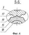
На фиг.1 изображено устройство для развальцовки труб в скважине в транспортном положении (разрез), на фиг.2 - устройство при развальцовке труб в скважине, на фиг.3 - вид А на фиг.1, на фиг.4 - сечение Б-Б на фиг.2.Figure 1 shows a device for expanding pipes in a well in a transport position (section), figure 2 - device when expanding pipes in a well, figure 3 - view A in figure 1, figure 4 - section B- B in figure 2.
Устройство для развальцовки труб в скважине (фиг.1) состоит из корпуса 1 с центральным каналом 2, резьб 3 для соединения со скважинным оборудованием и углублениями 4 на наружной поверхности, в которых размещены конические вальцующие ролики 5, установленные на осях 6. При этом нижние концы 7 осей 6 размещены в шарнирах 8, установленных в опорах 9 так, что оси 6 с роликами 5 можно отклонять от корпуса 1 в плоскости, проходящей через продольные геометрические оси корпуса 1 и роликов 5, и извлекать из шарниров 8 в случае их замены. Верхние концы 10 осей 6 закреплены с помощью втулки 11 в радиальных проточках 12 корпуса 1 с возможностью ограниченного перемещения наружу. Центральный канал 2 корпуса 1 содержит подпружиненный, благодаря пружине 13, гидравлический кольцевой поршень 14 с толкателем 15, имеющим наружную конусную поверхность 16.A device for expanding pipes in a well (Fig. 1) consists of a housing 1 with a central channel 2,
При этом ролики 5 (фиг.3, 4) по наружной поверхности оснащены продольными или смещенными, с целью увеличения эффекта «ввинчивания» (внедрения роликов в раздаваемую трубу по винтовой линии), под углом α выборками 17. Толкатель 15 (фиг.1, 4) размещен при помощи полой оси 18 снизу поршня 14 (фиг.1) соосно центральной оси корпуса 1 с возможностью вращения и взаимодействия изнутри с наружной поверхностью роликов 5, при выведении их в рабочее положение, своей конусной поверхностью 16, имеющей выступы 19 (фиг.4) под выборки 17 роликов 5.In this case, the rollers 5 (Figs. 3, 4) are equipped with longitudinal or offset along the outer surface in order to increase the effect of “screwing in” (introducing the rollers into the distributable pipe along a helical line) at an angle α of the
Устройство работает следующим образом.The device operates as follows.
В предварительно расширенный интервал 20 (фиг.1) (зона осложнения бурения) скважины 21 спускают профильные трубы 22 и расширяют их созданием внутреннего гидравлического давления до прижатия их стенок к стенке расширенного участка 20 скважины 21. Затем устройство при помощи резьб 3 корпуса 1 соединяют с колонной бурильных труб (не показано), в составе с которыми спускают в скважину 21. По достижении устройством верхнего конца труб 22 колонну бурильных труб начинают вращать при одновременном создании осевой нагрузки и промывки полости труб и устройства через центральный канал 2 корпуса 1 закачкой жидкости.In the previously expanded interval 20 (FIG. 1) (drilling complication zone) of the
При этом под действием перепада давления гидравлический кольцевой поршень 14 (фиг.2), сжимая пружину 13, перемещается вниз и, воздействуя через упорный подшипник 23 на толкатель 15, перемещает его вдоль полой оси 18 до взаимодействия своей наружной конусной поверхностью 16 с наружной поверхностью роликов 5, выводя их в рабочее положение. При этом выступы 19 (фиг.4) на конусной поверхности 16 (фиг.2) толкателя 15 входят в зацепление с выборками 17 (фиг.4) на наружной поверхности роликов 5 (фиг.2).In this case, under the influence of a differential pressure, the hydraulic annular piston 14 (FIG. 2), compressing the
При дальнейшем вращении колонны бурильных труб происходит выправление недожатых гидравлическим давлением стенок труб 22 (фиг.1) до плотного прижатия их к стенкам расширенного участка 20 скважины 21. Нагрузки, воздействующие на вальцующие ролики 5 при этом передаются на толкатель 15, заставляя его совершать вращательное движение вокруг центральной оси корпуса 1. Благодаря взаимодействию выборок 17 (фиг.4) роликов 5 с выступами 19 толкателя 15 исключается проскальзывание роликов 5 относительно развальцовываемых труб 22 (фиг.2), позволяя уменьшить осевую нагрузку на устройство и развальцовываемые им трубы 22.With further rotation of the drill pipe string, the walls of the
По окончании развальцовывания колонну бурильных труб с устройством поднимают из скважины.At the end of the flaring, the drill pipe string with the device is lifted from the well.
Предлагаемое устройство благодаря наличию на вальцующих роликах выборок, взаимодействующих с ответными выступами на толкателе, позволяет производить развальцовку труб без проскальзывания роликов, что значительно увеличивает ресурс роликов и позволяет более качественно развальцовывать профильные трубы, в том числе имеющие некруглые или искривленные поверхности.The proposed device, due to the presence on the rolling rollers of the samples interacting with the reciprocal protrusions on the pusher, allows the pipe to be expanded without slipping of the rollers, which significantly increases the resource of the rollers and allows higher quality flaring of the profile pipes, including those with non-circular or curved surfaces.
Claims (1)
Translated fromRussianPriority Applications (1)
| Application Number | Priority Date | Filing Date | Title |
|---|---|---|---|
| RU2009115486/03ARU2392415C1 (en) | 2009-04-23 | 2009-04-23 | Pipe flaring device |
Applications Claiming Priority (1)
| Application Number | Priority Date | Filing Date | Title |
|---|---|---|---|
| RU2009115486/03ARU2392415C1 (en) | 2009-04-23 | 2009-04-23 | Pipe flaring device |
Publications (1)
| Publication Number | Publication Date |
|---|---|
| RU2392415C1true RU2392415C1 (en) | 2010-06-20 |
Family
ID=42682766
Family Applications (1)
| Application Number | Title | Priority Date | Filing Date |
|---|---|---|---|
| RU2009115486/03ARU2392415C1 (en) | 2009-04-23 | 2009-04-23 | Pipe flaring device |
Country Status (1)
| Country | Link |
|---|---|
| RU (1) | RU2392415C1 (en) |
Cited By (1)
| Publication number | Priority date | Publication date | Assignee | Title |
|---|---|---|---|---|
| CN101979818A (en)* | 2010-10-28 | 2011-02-23 | 大庆油田有限责任公司 | Hydraulic reshaper |
Citations (5)
| Publication number | Priority date | Publication date | Assignee | Title |
|---|---|---|---|---|
| RU2235849C2 (en)* | 2002-07-22 | 2004-09-10 | Открытое акционерное общество "Татнефть" им. В.Д. Шашина | Method of tube expanding into well |
| EP1582274A2 (en)* | 1998-12-22 | 2005-10-05 | Weatherford/Lamb, Inc. | Procedures and equipment for profiling and jointing of pipes |
| RU64263U1 (en)* | 2007-01-25 | 2007-06-27 | Открытое акционерное общество "Татнефть" им. В.Д. Шашина | DEVICE FOR RIPPING PIPES IN A WELL |
| RU2322568C1 (en)* | 2006-08-04 | 2008-04-20 | ООО "Татнефть-Бурение" | Device for pipe expansion inside well |
| RU78856U1 (en)* | 2008-02-28 | 2008-12-10 | Открытое акционерное общество "Татнефть" им. В.Д. Шашина | DEVICE FOR FOLDING PIPES WITH A SHOE IN A WELL |
- 2009
- 2009-04-23RURU2009115486/03Apatent/RU2392415C1/ennot_activeIP Right Cessation
Patent Citations (5)
| Publication number | Priority date | Publication date | Assignee | Title |
|---|---|---|---|---|
| EP1582274A2 (en)* | 1998-12-22 | 2005-10-05 | Weatherford/Lamb, Inc. | Procedures and equipment for profiling and jointing of pipes |
| RU2235849C2 (en)* | 2002-07-22 | 2004-09-10 | Открытое акционерное общество "Татнефть" им. В.Д. Шашина | Method of tube expanding into well |
| RU2322568C1 (en)* | 2006-08-04 | 2008-04-20 | ООО "Татнефть-Бурение" | Device for pipe expansion inside well |
| RU64263U1 (en)* | 2007-01-25 | 2007-06-27 | Открытое акционерное общество "Татнефть" им. В.Д. Шашина | DEVICE FOR RIPPING PIPES IN A WELL |
| RU78856U1 (en)* | 2008-02-28 | 2008-12-10 | Открытое акционерное общество "Татнефть" им. В.Д. Шашина | DEVICE FOR FOLDING PIPES WITH A SHOE IN A WELL |
Cited By (2)
| Publication number | Priority date | Publication date | Assignee | Title |
|---|---|---|---|---|
| CN101979818A (en)* | 2010-10-28 | 2011-02-23 | 大庆油田有限责任公司 | Hydraulic reshaper |
| CN101979818B (en)* | 2010-10-28 | 2013-02-06 | 大庆油田有限责任公司 | Hydraulic reshaper |
Similar Documents
| Publication | Publication Date | Title |
|---|---|---|
| US11125036B2 (en) | Downhole anchor mechanism | |
| US20070163786A1 (en) | Expansion pig | |
| US11021921B2 (en) | Morphable anchor | |
| NO20110412L (en) | Procedure for installing an extension pipe | |
| US7308944B2 (en) | Expander tool for use in a wellbore | |
| RU2392415C1 (en) | Pipe flaring device | |
| RU2322568C1 (en) | Device for pipe expansion inside well | |
| RU2235849C2 (en) | Method of tube expanding into well | |
| NO337908B1 (en) | Pipe Expansion Tools and Procedures | |
| RU2459066C1 (en) | Device for extending tubes in well | |
| RU58155U1 (en) | DEVICE FOR RIPPING PIPES IN A WELL | |
| RU2394149C1 (en) | Expander-calibrator | |
| RU78856U1 (en) | DEVICE FOR FOLDING PIPES WITH A SHOE IN A WELL | |
| RU212818U1 (en) | Borehole flaring of the profile cover | |
| RU127805U1 (en) | SLIDING CENTER | |
| RU2387800C1 (en) | Pipe flaring device | |
| RU63845U1 (en) | WELL EQUIPMENT CENTER | |
| RU62967U1 (en) | PIPE FOLDING DEVICE | |
| RU62148U1 (en) | PIPE FOLDING DEVICE | |
| RU2612166C1 (en) | Expander | |
| RU2405103C1 (en) | Well pipe flaring device | |
| RU63850U1 (en) | DEVICE FOR EXPANSION OF PIPES IN A WELL | |
| RU2496962C1 (en) | Well reamer | |
| RU2420653C1 (en) | Device for local enlargement of profile and cylinder pipes in well | |
| RU2405908C1 (en) | Device for expansion of pipes in well |
Legal Events
| Date | Code | Title | Description |
|---|---|---|---|
| MM4A | The patent is invalid due to non-payment of fees | Effective date:20160424 |