RU2391893C2 - Device for tactile investigation of tissue density during endoscopic examination - Google Patents
Device for tactile investigation of tissue density during endoscopic examinationDownload PDFInfo
- Publication number
- RU2391893C2 RU2391893C2RU2008131482/14ARU2008131482ARU2391893C2RU 2391893 C2RU2391893 C2RU 2391893C2RU 2008131482/14 ARU2008131482/14 ARU 2008131482/14ARU 2008131482 ARU2008131482 ARU 2008131482ARU 2391893 C2RU2391893 C2RU 2391893C2
- Authority
- RU
- Russia
- Prior art keywords
- rod
- measuring modules
- tissue
- limit position
- endoscope
- Prior art date
Links
Images

Landscapes
- Endoscopes (AREA)
- Instruments For Viewing The Inside Of Hollow Bodies (AREA)
Abstract
Description
Translated fromRussianИзобретение относится к медицине и медицинской технике, в частности к практике и технике эндоскопии полых органов - желудка, 12-перстной кишки и др., а также других полостей организма (плевральная, брюшная полости, пространство малого таза и пр.).The invention relates to medicine and medical equipment, in particular to the practice and technique of endoscopy of hollow organs - the stomach,
Известен способ повышения точности обнаружения злокачественных новообразований и определения границ их локализации, при котором проводят осмотр пациента с помощью эндоскопа с подключенными к нему спектральным прибором и видеокамерой, измеряют интенсивности, спектры отражения и флуоресценции нормальных и подозреваемых участков на персональном компьютере и при обнаружении разницы в спектрах и при превышении интенсивности отраженного света от подозреваемого участка ткани по сравнению с нормальным более чем на 25% делают заключение о наличии злокачественного новообразования (RU 2152162, 10.07.2000).There is a method of increasing the accuracy of detecting malignant neoplasms and determining the boundaries of their localization, in which the patient is examined using an endoscope with a spectral device and a video camera connected to it, the intensities, reflection and fluorescence spectra of normal and suspected areas are measured on a personal computer and when differences in spectra are detected and if the intensity of reflected light from the suspected tissue site is higher than normal by more than 25%, they conclude that Alicia malignant neoplasms (RU 2152162, 07/10/2000).
Известны гибкие многофункциональные эндоскопы, содержащие оптическую систему из светопроводящих волокон, заключенных в гибкий каркас с возможностью управления рабочей частью, вводимой в обследуемую полость, а также с наличием рабочего канала, предназначенного для подведения и эвакуации жидкости, клея, лазерного светодиода, манипуляторов, в частности для забора биопсийного материала и с возможностью освещения (Дуоденофиброскоп, TJF-300, наружный d=13,0 мм, канал d=4,2 мм фирмы «Олимпус», Япония, каталог фирмы 2004 г.).Known flexible multifunctional endoscopes containing an optical system of light-conducting fibers enclosed in a flexible frame with the ability to control the working part introduced into the examined cavity, as well as with the presence of a working channel designed for supplying and evacuating liquid, glue, laser LEDs, manipulators, in particular for sampling biopsy material and with the possibility of lighting (Duodenofibroscope, TJF-300, external d = 13.0 mm, channel d = 4.2 mm from Olympus, Japan, catalog of the company in 2004).
Эти устройства не позволяют проводить исследование подлежащей ткани, находящейся в зоне осмотра, на предмет ее однородности и плотности, так как использует изменение оптических, а не механических свойств тканей.These devices do not allow the study of the underlying tissue in the inspection area for its uniformity and density, as it uses a change in the optical rather than mechanical properties of the tissues.
Известен контактный датчик давления для исследования полостей, имеющий заполненную газовой средой камеру, предназначенный для определения плотности слизистой оболочки носовых раковин (RU 2240028, 20.11.2004). Датчик подключен к средствам фиксации и обработки данных.Known contact pressure sensor for the study of cavities, having a chamber filled with a gas medium, designed to determine the density of the mucous membrane of the nasal concha (RU 2240028, 20.11.2004). The sensor is connected to the means of fixation and data processing.
Технические возможности этого устройства не позволяют проводить обследование в глубоких полостях тела.The technical capabilities of this device do not allow examination in deep body cavities.
Известна эндоскопическая система замера биофизических параметров ткани, в которой предусмотрен замер плотности ткани во время внутриполостного медицинского обследования (US 6711429, 23.03.2004), в котором осуществляется замер плотности подлежащей ткани сенсором на торце эндоскопа.Known endoscopic system for measuring biophysical parameters of tissue, which provides for measuring tissue density during intracavitary medical examination (US 6711429, 03/23/2004), in which the density of the underlying tissue is measured by a sensor at the endoscope end.
Однако система не позволяет формировать у исследователя эффект, сходный с непосредственным осязанием осматриваемого объекта.However, the system does not allow the researcher to form an effect similar to the direct touch of the object being examined.
Известно устройство для определения вязкоупругих свойств мягких тканей, содержащее цилиндрический корпус, внутри которого установлен вибратор с датчиком силы, соединенные соответственно с генератором сигналов и с элементами обработки и регистрации сигнала силы и смонтированные через опорную площадку с контактным штампом, контактный штамп прикреплен посредством резьбы к опорной площадке и выполнен плоским в торце и с возможностью выступа с торцевой части корпуса (RU 2082312, 28.07.1993).A device is known for determining the viscoelastic properties of soft tissues, comprising a cylindrical body, inside which a vibrator with a force sensor is mounted, connected respectively to a signal generator and to elements for processing and recording a force signal and mounted through a support pad with a contact stamp, the contact stamp is attached by a thread to the support platform and made flat at the end and with the possibility of protrusion from the end of the housing (RU 2082312, 07.28.1993).
Недостатком устройства является невозможность сравнения соседних участков исследуемого образца.The disadvantage of this device is the inability to compare neighboring sections of the test sample.
Известно устройство для исследования ткани молочной железы (US 6091981, 18.07.2000), которое содержит множество датчиков, размещенных на поверхности, контактирующей с исследуемой тканью, каждый из которых измеряет локальное давление, действующее на него со стороны ткани в ответ на силу, с которой врач прижимает устройство к исследуемой ткани. В зависимости от структуры подлежащей ткани изменяется распределение давлений между датчиками, что позволяет после соответствующей обработки сигналов выделить зоны с измененными физическими свойствами.A device for researching breast tissue (US 6091981, July 18, 2000) is known, which comprises a plurality of sensors placed on the surface in contact with the tissue under investigation, each of which measures the local pressure exerted on it by the tissue in response to the force with which the doctor presses the device to the test tissue. Depending on the structure of the underlying tissue, the pressure distribution between the sensors changes, which allows, after appropriate signal processing, to identify zones with altered physical properties.
Недостатком устройства является отсутствие измерения перемещения контактной поверхности в направлении ткани и суммарной силы воздействия на ткань, что не позволяет оценить усредненные упругопластические свойства биологической ткани. Другим недостатком является выполнение контактной поверхности из слабодеформируемого материала, что при исследовании образцов тканей с выраженными локальными изменениями, такими как пузырьки в легких при пневмонии или наличие участков обызвествления, может приводить к быстрым необратимым изменениям в структуре ткани и искажению объективной информации.The disadvantage of this device is the lack of measurement of the movement of the contact surface in the direction of the tissue and the total force acting on the tissue, which does not allow to evaluate the averaged elastoplastic properties of biological tissue. Another drawback is that the contact surface is made of a poorly deformed material, which, when examining tissue samples with pronounced local changes, such as pulmonary vesicles during pneumonia or the presence of calcification sites, can lead to rapid irreversible changes in the structure of the tissue and distortion of objective information.
Наиболее близким к заявляемому изобретению является устройство для исследования плотности ткани при эндоскопическом исследовании (RU 2286080, 27.10.2006), содержащее эндоскоп с датчиками плотности ткани, подключенными к компьютерной системе, причем датчиками плотности ткани являются датчики давления, установленные на торце эндоскопа, а компьютерная система выполнена с возможностью раздельной фиксации каждым датчиком давления плотности подлежащего участка ткани и регистрации сопротивления давлению в динамическом режиме.Closest to the claimed invention is a device for studying tissue density during endoscopic examination (RU 2286080, 10.27.2006), containing an endoscope with tissue density sensors connected to a computer system, and tissue density sensors are pressure sensors mounted on the endoscope end, and computer the system is made with the possibility of separate fixation by each pressure sensor of the density of the underlying tissue site and registration of resistance to pressure in a dynamic mode.
Недостатком устройства является значительная зависимость измеряемых величин от свойств материала и точности изготовления чувствительных элементов. Так же устройство не обеспечивает обратной связи для управления силой прижима чувствительных элементов к исследуемому образцу.The disadvantage of this device is the significant dependence of the measured values on the properties of the material and the accuracy of manufacturing of sensitive elements. Also, the device does not provide feedback to control the force of pressure of the sensitive elements to the test sample.
Технический результат, на достижение которого направлено предлагаемое изобретение, заключается в повышении эффективности исследования за счет снижения зависимости измеряемых величин от свойств материала и обеспечения обратной связи для управления силой прижима чувствительных элементов к исследуемому образцу.The technical result, the achievement of which the present invention is directed, is to increase the research efficiency by reducing the dependence of the measured values on the properties of the material and providing feedback for controlling the force of pressure of the sensitive elements to the test sample.
Технический результат достигается тем, что в устройстве для исследования плотности ткани при эндоскопическом исследовании, содержащем эндоскоп с датчиками плотности ткани, установленными на торце эндоскопа, и компьютер, выполненной с возможностью регистрации давления плотности подлежащего участка ткани и сопротивления давлению от каждого датчика, датчики плотности ткани выполнены в виде матрицы сменных измерительных модулей, установленных в несущей пластине, при этом каждый модуль состоит из корпуса, в сквозном отверстии которого установлен с возможностью перемещения под действием пружины шток, снабженный на выступающем из отверстия корпуса конце сменным наконечником, противоположная сторона сквозного отверстия перекрыта крышкой с закрепленным на ней датчиком измерения хода штока, подключенным к усилителю сигнала, выходы всех усилителей соединены со входом сумматора приложенных сил, выход которого подключен ко входу элемента индикации приложенных сил, выход каждого усилителя сигнала соединен также с первыми входами соответствующих блоков контроля верхнего и нижнего предельных положений штока, ко вторым входам которых подсоединены источники опорного напряжения верхнего и нижнего предельных положений штока, выходы блоков контроля верхнего предельного положения штока всех измерительных модулей соединены со входами элемента «ИЛИ» верхнего предельного положения штока, выходы блоков контроля нижнего предельного положения штока всех измерительных модулей соединены со входами элемента «ИЛИ» нижнего предельного положения штока, выходы обоих элементов «ИЛИ» подключены к элементам индикации верхнего и нижнего предельных положений штока, при этом усилители сигнала, сумматор и элементы «ИЛИ» верхнего и нижнего предельного положения штока подключены к контроллеру порта параллельного ввода-вывода компьютера.The technical result is achieved by the fact that in the device for studying tissue density during endoscopic examination, containing an endoscope with tissue density sensors mounted on the endoscope end face, and a computer configured to register the density density of the underlying tissue site and pressure resistance from each sensor, tissue density sensors made in the form of a matrix of interchangeable measuring modules installed in the carrier plate, with each module consisting of a housing, in the through hole of which the rod is mounted with the possibility of movement under the action of the spring, equipped with a replaceable tip on the end protruding from the housing opening, the opposite side of the through hole is closed by a cover with a rod stroke measuring sensor attached to it, connected to the signal amplifier, the outputs of all amplifiers are connected to the input of the applied forces adder, output which is connected to the input of the indication element of the applied forces, the output of each signal amplifier is also connected to the first inputs of the corresponding control units of the upper and the lower limit positions of the rod, to the second inputs of which are connected the voltage sources of the upper and lower limit positions of the rod, the outputs of the control units of the upper limit position of the rod of all measuring modules are connected to the inputs of the element "OR" of the upper limit position of the rod, the outputs of the control units of the lower limit position of the rod all measuring modules are connected to the inputs of the element "OR" the lower limit position of the rod, the outputs of both elements "OR" are connected to the display elements in the upper and lower limit positions of the rod, while the signal amplifiers, the adder and the elements "OR" of the upper and lower limit positions of the rod are connected to the controller of the parallel input-output port of the computer.
Предпочтительно, чтобы сменные измерительные модули были установлены в несущей пластине посредством резьбового соединения.Preferably, interchangeable measuring modules are mounted in the carrier plate by means of a threaded connection.
Матрица сменных измерительных модулей на торце эндоскопа может быть закрыта гибкой защитной оболочкой.The matrix of interchangeable measuring modules at the endoscope end can be covered by a flexible protective sheath.
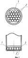
На фиг.1 показана матрица сменных измерительных модулей на торце эндоскопа, на фиг.2 - отдельный измерительный модуль эндоскопа, на фиг.3 - блок-схема устройства для исследования плотности ткани.Figure 1 shows a matrix of interchangeable measuring modules at the endoscope end face, figure 2 - a separate measuring module of the endoscope, figure 3 is a block diagram of a device for studying tissue density.
Матрица сменных измерительных модулей на торце эндоскопа состоит из несущей пластины 1 (фиг.1), в которую посредством резьбового соединения вворачиваются измерительные модули 2 эндоскопа. Количество измерительных модулей 2, размещаемых на пластине 1 наборного поля эндоскопа, может быть различным в зависимости от условий диагностики. Все измерительные модули 2 эндоскопа перекрыты общей гибкой защитной оболочкой 3.The matrix of interchangeable measuring modules at the endoscope end consists of a carrier plate 1 (Fig. 1), into which the
Отдельный измерительный модуль 2 (фиг.2) эндоскопа состоит из корпуса 4 модуля, в сквозном отверстии которого установлен с возможностью перемещения под действием пружины 8 шток 7, снабженный на выступающем из отверстия корпуса конце сменным наконечником 9, противоположная сторона сквозного отверстия перекрыта крышкой 5 с закрепленным на ней датчиком измерения 6 хода штока, подключенным проводами 10 к усилителю сигнала 6. Пружина 8 и наконечник 9 могут заменяться в зависимости от требований диагностического исследования.A separate measuring module 2 (Fig. 2) of the endoscope consists of a
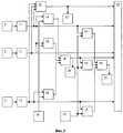
Электрическая схема эндоскопа (фиг.3) содержит N датчиков измерения 6 хода штока в N измерительных модулях 2 эндоскопа, N усилителей 11 сигналов измерительных модулей, сумматор 12 сигналов приложенных сил с элементом индикации 13 приложенных сил, N блоков контроля верхнего 14 предельного положения штока 7, N блоков контроля нижнего 15 предельного положения штока 7, источник опорного напряжения верхнего 16 предельного положения штока 7, источник опорного напряжения нижнего 17 предельного положения штока 7, элемент «ИЛИ» верхнего 18 предельного положения штока 7, элемент «ИЛИ» нижнего 19 предельного положения штока 7, элемент индикации верхнего 20 предельного положения штока 7, элемент индикации нижнего 21 предельного положения штока 7 и компьютер 22.The electric circuit of the endoscope (Fig. 3) contains N sensors for measuring 6 stroke of the rod in
Проводники 10 датчиков 6 измерения хода штока N измерительных модулей 2 эндоскопа подключены к N усилителям 11 сигналов. Выходы N усилителей 11 сигналов соединены со входом сумматора 12 приложенных сил, выход которого соединен с элементом индикации 13 приложенных сил. Кроме того, выходы N усилителей 11 сигналов подсоединены к первым входам N блоков контроля верхнего 14 и N блоков контроля нижнего 15 предельного положения штока 7, ко вторым входам которых подсоединены источник опорного напряжения верхнего 16 и нижнего 17 предельного положения штока 7, соответственно. Выходы N блоков контроля верхнего 14 предельного положения штока 7 подсоединены ко входам элемента «ИЛИ» верхнего 18 предельного положения штока 7, выходы N блоков контроля нижнего 15 предельного положения штока 7 подсоединены ко входам элемента «ИЛИ» нижнего 19 предельного положения штока 7, выходы элемента «ИЛИ» верхнего 18 и элемента «ИЛИ» нижнего 19 предельного положения штока 7 подсоединены к входам элементов индикации верхнего 20 и нижнего 21 предельного положения штока 7. Усилители сигнала 11, сумматор 12 и элементы «ИЛИ» верхнего и нижнего предельного положения штока 18, 19 подключены к контроллеру порта параллельного ввода-вывода компьютера 22.The
Устройство работает следующим образом.The device operates as follows.
В процессе обследования N модулей 2 на несущей пластине 1 матрицы сменных измерительных модулей на торце эндоскопа через гибкую защитную оболочку 3 контактируют с исследуемым образцом.In the process of examining
В случае неоднородности исследуемого образца пружины 8 измерительных модулей 2 эндоскопа сжимаются, перемещая шток 7 с наконечником на его конце на соответствующую каждому модулю величину Δli, i=1…N (фиг.2), что фиксируется датчиком 6 измерения хода штока 7. В результате на проводниках 10 формируется напряжение, пропорциональное величине Δli. Это напряжение усиливается усилителями 11 сигналов измерительных модулей (фиг.3) с коэффициентами усиления, пропорциональными значениям жесткости пружин 8. На выходах усилителей 11 формируются сигналы, пропорциональные силам сжатия Fi=K·Δli, где К - коэффициент жесткости пружины, Δli - величина хода штока для отдельного измерительного модуля. Эти сигналы суммируются на сумматоре 12 сигналов приложенных сил и общая величина, пропорциональная суммарному значению F, отображается элементом индикации 13 приложенных сил. В процессе исследования к эндоскопу должна прикладываться такая сила, при которой шток 7 не должен достигать предельных положений. Индикация предельных положений штока 7 обеспечивается сравнением напряжений с усилителей 11 сигналов измерительных модулей 2 с напряжениями от источников опорного напряжения верхнего 16 и нижнего 17 предельного положения штока 7 на блоках контроля верхнего 14 и нижнего 15 предельных положений штока 7 и отображением на элементах индикации верхнего 20 и нижнего 21 предельного положения штока 7.In the case of heterogeneity of the test sample, the
Сигналы, пропорциональные силам Fi сжатия пружин 8, с усилителей 11 сигналов измерительных модулей подаются через соответствующий ввод-вывод контроллера порта на компьютер 22. Так же на компьютер 22 с сумматора 12 сигналов приложенных сил подается сигнал, пропорциональный сумме всех приложенных сил. Кроме того, на компьютер 22 от элементов «ИЛИ» верхнего 18 и нижнего 19 предельных положений штока 7 подаются сигналы о выходе хотя бы одного из штоков 7 измерительных модулей 2 в верхнее или нижнее крайние положения. На основе этих сигналов компьютер 22 производит графическое и табличное отображение во времени всех поступающих величин.The signals proportional to the compression forces Fi of the springs 8 from the
Такое техническое решение позволяет снизить зависимость измеряемых величин от свойств материала и обеспечить оператора информацией для управления силой прижима чувствительных элементов к исследуемому образцу. Это облегчает обучение операторов и позволяет расширить информацию для последующего клинического использования. Предложенное устройство относительно просто и разработано с возможностью дальнейшего сочетания с различными эндоскопическими аппаратами.This technical solution allows to reduce the dependence of the measured values on the properties of the material and provide the operator with information to control the force of pressure of the sensitive elements to the test sample. This facilitates the training of operators and allows you to expand the information for subsequent clinical use. The proposed device is relatively simple and designed with the possibility of further combination with various endoscopic devices.
Claims (3)
Translated fromRussianPriority Applications (1)
| Application Number | Priority Date | Filing Date | Title |
|---|---|---|---|
| RU2008131482/14ARU2391893C2 (en) | 2008-07-31 | 2008-07-31 | Device for tactile investigation of tissue density during endoscopic examination |
Applications Claiming Priority (1)
| Application Number | Priority Date | Filing Date | Title |
|---|---|---|---|
| RU2008131482/14ARU2391893C2 (en) | 2008-07-31 | 2008-07-31 | Device for tactile investigation of tissue density during endoscopic examination |
Publications (2)
| Publication Number | Publication Date |
|---|---|
| RU2008131482A RU2008131482A (en) | 2010-02-10 |
| RU2391893C2true RU2391893C2 (en) | 2010-06-20 |
Family
ID=42123371
Family Applications (1)
| Application Number | Title | Priority Date | Filing Date |
|---|---|---|---|
| RU2008131482/14ARU2391893C2 (en) | 2008-07-31 | 2008-07-31 | Device for tactile investigation of tissue density during endoscopic examination |
Country Status (1)
| Country | Link |
|---|---|
| RU (1) | RU2391893C2 (en) |
Cited By (1)
| Publication number | Priority date | Publication date | Assignee | Title |
|---|---|---|---|---|
| RU2804287C2 (en)* | 2022-02-21 | 2023-09-26 | Частное Учреждение По Обеспечению Научного Развития Атомной Отрасли "Наука И Инновации" (Частное Учреждение "Наука И Инновации") | Method for registration and processing of optical biopsy data in dynamic mode |
Citations (2)
| Publication number | Priority date | Publication date | Assignee | Title |
|---|---|---|---|---|
| US5339799A (en)* | 1991-04-23 | 1994-08-23 | Olympus Optical Co., Ltd. | Medical system for reproducing a state of contact of the treatment section in the operation unit |
| RU2286080C2 (en)* | 2005-01-26 | 2006-10-27 | Общество с ограниченной ответственностью "ТАКТИЛ" (ООО "ТАКТИЛ") | Device for inspection of density of tissue at endoscope testing |
- 2008
- 2008-07-31RURU2008131482/14Apatent/RU2391893C2/ennot_activeIP Right Cessation
Patent Citations (2)
| Publication number | Priority date | Publication date | Assignee | Title |
|---|---|---|---|---|
| US5339799A (en)* | 1991-04-23 | 1994-08-23 | Olympus Optical Co., Ltd. | Medical system for reproducing a state of contact of the treatment section in the operation unit |
| RU2286080C2 (en)* | 2005-01-26 | 2006-10-27 | Общество с ограниченной ответственностью "ТАКТИЛ" (ООО "ТАКТИЛ") | Device for inspection of density of tissue at endoscope testing |
Non-Patent Citations (1)
| Title |
|---|
| САДОВНИЧИЙ В.А. и др. Искусственный тактильный механорецептор. Теория, опыт создания, экспериментальная апробация. Ж. Технология живых систем, № 4 и 5, 2005, с.8-15.* |
Cited By (1)
| Publication number | Priority date | Publication date | Assignee | Title |
|---|---|---|---|---|
| RU2804287C2 (en)* | 2022-02-21 | 2023-09-26 | Частное Учреждение По Обеспечению Научного Развития Атомной Отрасли "Наука И Инновации" (Частное Учреждение "Наука И Инновации") | Method for registration and processing of optical biopsy data in dynamic mode |
Also Published As
| Publication number | Publication date |
|---|---|
| RU2008131482A (en) | 2010-02-10 |
Similar Documents
| Publication | Publication Date | Title |
|---|---|---|
| Jun et al. | Fully integrated silicon probes for high-density recording of neural activity | |
| US6376233B1 (en) | Device for conducting research on cell specimens and similar materials | |
| KR100506084B1 (en) | Apparatus and method for searching acupuncture point | |
| JP3328810B2 (en) | Apparatus for quantitatively measuring the distribution of local measurands | |
| EP1262763A2 (en) | Spatially resolved optical measurements | |
| RU2138192C1 (en) | Method of identification of tissue type and apparatus for method embodiment | |
| JP2016507059A5 (en) | ||
| Kamal et al. | Engineering approaches for breast cancer diagnosis: a review | |
| JPH1164215A (en) | Measuring instrument | |
| PL219558B1 (en) | Device and method for the diagnosis of secondary caries | |
| Ruiz-Vargas et al. | Design, construction and validation of an electrical impedance probe with contact force and temperature sensors suitable for in-vivo measurements | |
| JP3595827B1 (en) | Measurement method of bulk modulus of micro sample | |
| JP2004527300A (en) | Method and apparatus for detecting functional and metabolic data of a living body | |
| US7709246B2 (en) | Device and method for detecting bioelectric signals from electrophysiologically active regions in spheroids | |
| RU2286080C2 (en) | Device for inspection of density of tissue at endoscope testing | |
| RU2391893C2 (en) | Device for tactile investigation of tissue density during endoscopic examination | |
| RU144665U1 (en) | DEVICE FOR RAMAN-FLUORESCENT DIAGNOSTICS OF THE CONDITION OF HUMAN TISSUES IN NORMALITY AND IN PATHOLOGY | |
| RU2440016C2 (en) | Device for testing biological tissue density | |
| CN101313838A (en) | In vivo hyperspectral imaging diagnostic instrument | |
| Latha et al. | Design and development of A microcontroller based system for the measurement of blood glucose | |
| WO2024025891A1 (en) | System for simultaneous contractile force and calcium/voltage transient measurement of engineered tissue | |
| RU2515481C1 (en) | Adaptive device for biological tissue elasticity research in endoscopic examination | |
| JP2018013453A (en) | Method and device for measuring sensibility of anticancer drug | |
| US7041951B2 (en) | Method and apparatus for investigating layers of tissues in living animals using a microscope | |
| US8876735B2 (en) | Apparatus and methods for identifying a tissue inside a living body |
Legal Events
| Date | Code | Title | Description |
|---|---|---|---|
| MM4A | The patent is invalid due to non-payment of fees | Effective date:20100801 |