RU2388624C2 - System of high-temperature batteries for hybrid locomotive and off-road vehicles - Google Patents
System of high-temperature batteries for hybrid locomotive and off-road vehiclesDownload PDFInfo
- Publication number
- RU2388624C2 RU2388624C2RU2007104039/11ARU2007104039ARU2388624C2RU 2388624 C2RU2388624 C2RU 2388624C2RU 2007104039/11 ARU2007104039/11 ARU 2007104039/11ARU 2007104039 ARU2007104039 ARU 2007104039ARU 2388624 C2RU2388624 C2RU 2388624C2
- Authority
- RU
- Russia
- Prior art keywords
- battery
- temperature
- vehicle
- batteries
- electric
- Prior art date
Links
Images


Classifications
- B—PERFORMING OPERATIONS; TRANSPORTING
- B60—VEHICLES IN GENERAL
- B60K—ARRANGEMENT OR MOUNTING OF PROPULSION UNITS OR OF TRANSMISSIONS IN VEHICLES; ARRANGEMENT OR MOUNTING OF PLURAL DIVERSE PRIME-MOVERS IN VEHICLES; AUXILIARY DRIVES FOR VEHICLES; INSTRUMENTATION OR DASHBOARDS FOR VEHICLES; ARRANGEMENTS IN CONNECTION WITH COOLING, AIR INTAKE, GAS EXHAUST OR FUEL SUPPLY OF PROPULSION UNITS IN VEHICLES
- B60K6/00—Arrangement or mounting of plural diverse prime-movers for mutual or common propulsion, e.g. hybrid propulsion systems comprising electric motors and internal combustion engines
- B60K6/20—Arrangement or mounting of plural diverse prime-movers for mutual or common propulsion, e.g. hybrid propulsion systems comprising electric motors and internal combustion engines the prime-movers consisting of electric motors and internal combustion engines, e.g. HEVs
- B60K6/22—Arrangement or mounting of plural diverse prime-movers for mutual or common propulsion, e.g. hybrid propulsion systems comprising electric motors and internal combustion engines the prime-movers consisting of electric motors and internal combustion engines, e.g. HEVs characterised by apparatus, components or means specially adapted for HEVs
- B60K6/28—Arrangement or mounting of plural diverse prime-movers for mutual or common propulsion, e.g. hybrid propulsion systems comprising electric motors and internal combustion engines the prime-movers consisting of electric motors and internal combustion engines, e.g. HEVs characterised by apparatus, components or means specially adapted for HEVs characterised by the electric energy storing means, e.g. batteries or capacitors
- B—PERFORMING OPERATIONS; TRANSPORTING
- B60—VEHICLES IN GENERAL
- B60K—ARRANGEMENT OR MOUNTING OF PROPULSION UNITS OR OF TRANSMISSIONS IN VEHICLES; ARRANGEMENT OR MOUNTING OF PLURAL DIVERSE PRIME-MOVERS IN VEHICLES; AUXILIARY DRIVES FOR VEHICLES; INSTRUMENTATION OR DASHBOARDS FOR VEHICLES; ARRANGEMENTS IN CONNECTION WITH COOLING, AIR INTAKE, GAS EXHAUST OR FUEL SUPPLY OF PROPULSION UNITS IN VEHICLES
- B60K6/00—Arrangement or mounting of plural diverse prime-movers for mutual or common propulsion, e.g. hybrid propulsion systems comprising electric motors and internal combustion engines
- B60K6/20—Arrangement or mounting of plural diverse prime-movers for mutual or common propulsion, e.g. hybrid propulsion systems comprising electric motors and internal combustion engines the prime-movers consisting of electric motors and internal combustion engines, e.g. HEVs
- B60K6/42—Arrangement or mounting of plural diverse prime-movers for mutual or common propulsion, e.g. hybrid propulsion systems comprising electric motors and internal combustion engines the prime-movers consisting of electric motors and internal combustion engines, e.g. HEVs characterised by the architecture of the hybrid electric vehicle
- B60K6/46—Series type
- B—PERFORMING OPERATIONS; TRANSPORTING
- B60—VEHICLES IN GENERAL
- B60L—PROPULSION OF ELECTRICALLY-PROPELLED VEHICLES; SUPPLYING ELECTRIC POWER FOR AUXILIARY EQUIPMENT OF ELECTRICALLY-PROPELLED VEHICLES; ELECTRODYNAMIC BRAKE SYSTEMS FOR VEHICLES IN GENERAL; MAGNETIC SUSPENSION OR LEVITATION FOR VEHICLES; MONITORING OPERATING VARIABLES OF ELECTRICALLY-PROPELLED VEHICLES; ELECTRIC SAFETY DEVICES FOR ELECTRICALLY-PROPELLED VEHICLES
- B60L3/00—Electric devices on electrically-propelled vehicles for safety purposes; Monitoring operating variables, e.g. speed, deceleration or energy consumption
- B60L3/0023—Detecting, eliminating, remedying or compensating for drive train abnormalities, e.g. failures within the drive train
- B60L3/0046—Detecting, eliminating, remedying or compensating for drive train abnormalities, e.g. failures within the drive train relating to electric energy storage systems, e.g. batteries or capacitors
- B—PERFORMING OPERATIONS; TRANSPORTING
- B60—VEHICLES IN GENERAL
- B60L—PROPULSION OF ELECTRICALLY-PROPELLED VEHICLES; SUPPLYING ELECTRIC POWER FOR AUXILIARY EQUIPMENT OF ELECTRICALLY-PROPELLED VEHICLES; ELECTRODYNAMIC BRAKE SYSTEMS FOR VEHICLES IN GENERAL; MAGNETIC SUSPENSION OR LEVITATION FOR VEHICLES; MONITORING OPERATING VARIABLES OF ELECTRICALLY-PROPELLED VEHICLES; ELECTRIC SAFETY DEVICES FOR ELECTRICALLY-PROPELLED VEHICLES
- B60L58/00—Methods or circuit arrangements for monitoring or controlling batteries or fuel cells, specially adapted for electric vehicles
- B60L58/10—Methods or circuit arrangements for monitoring or controlling batteries or fuel cells, specially adapted for electric vehicles for monitoring or controlling batteries
- B60L58/12—Methods or circuit arrangements for monitoring or controlling batteries or fuel cells, specially adapted for electric vehicles for monitoring or controlling batteries responding to state of charge [SoC]
- B—PERFORMING OPERATIONS; TRANSPORTING
- B60—VEHICLES IN GENERAL
- B60L—PROPULSION OF ELECTRICALLY-PROPELLED VEHICLES; SUPPLYING ELECTRIC POWER FOR AUXILIARY EQUIPMENT OF ELECTRICALLY-PROPELLED VEHICLES; ELECTRODYNAMIC BRAKE SYSTEMS FOR VEHICLES IN GENERAL; MAGNETIC SUSPENSION OR LEVITATION FOR VEHICLES; MONITORING OPERATING VARIABLES OF ELECTRICALLY-PROPELLED VEHICLES; ELECTRIC SAFETY DEVICES FOR ELECTRICALLY-PROPELLED VEHICLES
- B60L58/00—Methods or circuit arrangements for monitoring or controlling batteries or fuel cells, specially adapted for electric vehicles
- B60L58/10—Methods or circuit arrangements for monitoring or controlling batteries or fuel cells, specially adapted for electric vehicles for monitoring or controlling batteries
- B60L58/24—Methods or circuit arrangements for monitoring or controlling batteries or fuel cells, specially adapted for electric vehicles for monitoring or controlling batteries for controlling the temperature of batteries
- B60L58/25—Methods or circuit arrangements for monitoring or controlling batteries or fuel cells, specially adapted for electric vehicles for monitoring or controlling batteries for controlling the temperature of batteries by controlling the electric load
- B—PERFORMING OPERATIONS; TRANSPORTING
- B60—VEHICLES IN GENERAL
- B60L—PROPULSION OF ELECTRICALLY-PROPELLED VEHICLES; SUPPLYING ELECTRIC POWER FOR AUXILIARY EQUIPMENT OF ELECTRICALLY-PROPELLED VEHICLES; ELECTRODYNAMIC BRAKE SYSTEMS FOR VEHICLES IN GENERAL; MAGNETIC SUSPENSION OR LEVITATION FOR VEHICLES; MONITORING OPERATING VARIABLES OF ELECTRICALLY-PROPELLED VEHICLES; ELECTRIC SAFETY DEVICES FOR ELECTRICALLY-PROPELLED VEHICLES
- B60L58/00—Methods or circuit arrangements for monitoring or controlling batteries or fuel cells, specially adapted for electric vehicles
- B60L58/10—Methods or circuit arrangements for monitoring or controlling batteries or fuel cells, specially adapted for electric vehicles for monitoring or controlling batteries
- B60L58/24—Methods or circuit arrangements for monitoring or controlling batteries or fuel cells, specially adapted for electric vehicles for monitoring or controlling batteries for controlling the temperature of batteries
- B60L58/26—Methods or circuit arrangements for monitoring or controlling batteries or fuel cells, specially adapted for electric vehicles for monitoring or controlling batteries for controlling the temperature of batteries by cooling
- B—PERFORMING OPERATIONS; TRANSPORTING
- B60—VEHICLES IN GENERAL
- B60L—PROPULSION OF ELECTRICALLY-PROPELLED VEHICLES; SUPPLYING ELECTRIC POWER FOR AUXILIARY EQUIPMENT OF ELECTRICALLY-PROPELLED VEHICLES; ELECTRODYNAMIC BRAKE SYSTEMS FOR VEHICLES IN GENERAL; MAGNETIC SUSPENSION OR LEVITATION FOR VEHICLES; MONITORING OPERATING VARIABLES OF ELECTRICALLY-PROPELLED VEHICLES; ELECTRIC SAFETY DEVICES FOR ELECTRICALLY-PROPELLED VEHICLES
- B60L58/00—Methods or circuit arrangements for monitoring or controlling batteries or fuel cells, specially adapted for electric vehicles
- B60L58/10—Methods or circuit arrangements for monitoring or controlling batteries or fuel cells, specially adapted for electric vehicles for monitoring or controlling batteries
- B60L58/24—Methods or circuit arrangements for monitoring or controlling batteries or fuel cells, specially adapted for electric vehicles for monitoring or controlling batteries for controlling the temperature of batteries
- B60L58/27—Methods or circuit arrangements for monitoring or controlling batteries or fuel cells, specially adapted for electric vehicles for monitoring or controlling batteries for controlling the temperature of batteries by heating
- B—PERFORMING OPERATIONS; TRANSPORTING
- B60—VEHICLES IN GENERAL
- B60L—PROPULSION OF ELECTRICALLY-PROPELLED VEHICLES; SUPPLYING ELECTRIC POWER FOR AUXILIARY EQUIPMENT OF ELECTRICALLY-PROPELLED VEHICLES; ELECTRODYNAMIC BRAKE SYSTEMS FOR VEHICLES IN GENERAL; MAGNETIC SUSPENSION OR LEVITATION FOR VEHICLES; MONITORING OPERATING VARIABLES OF ELECTRICALLY-PROPELLED VEHICLES; ELECTRIC SAFETY DEVICES FOR ELECTRICALLY-PROPELLED VEHICLES
- B60L2200/00—Type of vehicles
- B60L2200/26—Rail vehicles
- B—PERFORMING OPERATIONS; TRANSPORTING
- B60—VEHICLES IN GENERAL
- B60L—PROPULSION OF ELECTRICALLY-PROPELLED VEHICLES; SUPPLYING ELECTRIC POWER FOR AUXILIARY EQUIPMENT OF ELECTRICALLY-PROPELLED VEHICLES; ELECTRODYNAMIC BRAKE SYSTEMS FOR VEHICLES IN GENERAL; MAGNETIC SUSPENSION OR LEVITATION FOR VEHICLES; MONITORING OPERATING VARIABLES OF ELECTRICALLY-PROPELLED VEHICLES; ELECTRIC SAFETY DEVICES FOR ELECTRICALLY-PROPELLED VEHICLES
- B60L2210/00—Converter types
- B60L2210/20—AC to AC converters
- B—PERFORMING OPERATIONS; TRANSPORTING
- B60—VEHICLES IN GENERAL
- B60L—PROPULSION OF ELECTRICALLY-PROPELLED VEHICLES; SUPPLYING ELECTRIC POWER FOR AUXILIARY EQUIPMENT OF ELECTRICALLY-PROPELLED VEHICLES; ELECTRODYNAMIC BRAKE SYSTEMS FOR VEHICLES IN GENERAL; MAGNETIC SUSPENSION OR LEVITATION FOR VEHICLES; MONITORING OPERATING VARIABLES OF ELECTRICALLY-PROPELLED VEHICLES; ELECTRIC SAFETY DEVICES FOR ELECTRICALLY-PROPELLED VEHICLES
- B60L2260/00—Operating Modes
- B60L2260/40—Control modes
- B60L2260/50—Control modes by future state prediction
- B60L2260/56—Temperature prediction, e.g. for pre-cooling
- Y—GENERAL TAGGING OF NEW TECHNOLOGICAL DEVELOPMENTS; GENERAL TAGGING OF CROSS-SECTIONAL TECHNOLOGIES SPANNING OVER SEVERAL SECTIONS OF THE IPC; TECHNICAL SUBJECTS COVERED BY FORMER USPC CROSS-REFERENCE ART COLLECTIONS [XRACs] AND DIGESTS
- Y02—TECHNOLOGIES OR APPLICATIONS FOR MITIGATION OR ADAPTATION AGAINST CLIMATE CHANGE
- Y02T—CLIMATE CHANGE MITIGATION TECHNOLOGIES RELATED TO TRANSPORTATION
- Y02T10/00—Road transport of goods or passengers
- Y02T10/60—Other road transportation technologies with climate change mitigation effect
- Y02T10/62—Hybrid vehicles
- Y—GENERAL TAGGING OF NEW TECHNOLOGICAL DEVELOPMENTS; GENERAL TAGGING OF CROSS-SECTIONAL TECHNOLOGIES SPANNING OVER SEVERAL SECTIONS OF THE IPC; TECHNICAL SUBJECTS COVERED BY FORMER USPC CROSS-REFERENCE ART COLLECTIONS [XRACs] AND DIGESTS
- Y02—TECHNOLOGIES OR APPLICATIONS FOR MITIGATION OR ADAPTATION AGAINST CLIMATE CHANGE
- Y02T—CLIMATE CHANGE MITIGATION TECHNOLOGIES RELATED TO TRANSPORTATION
- Y02T10/00—Road transport of goods or passengers
- Y02T10/60—Other road transportation technologies with climate change mitigation effect
- Y02T10/64—Electric machine technologies in electromobility
- Y—GENERAL TAGGING OF NEW TECHNOLOGICAL DEVELOPMENTS; GENERAL TAGGING OF CROSS-SECTIONAL TECHNOLOGIES SPANNING OVER SEVERAL SECTIONS OF THE IPC; TECHNICAL SUBJECTS COVERED BY FORMER USPC CROSS-REFERENCE ART COLLECTIONS [XRACs] AND DIGESTS
- Y02—TECHNOLOGIES OR APPLICATIONS FOR MITIGATION OR ADAPTATION AGAINST CLIMATE CHANGE
- Y02T—CLIMATE CHANGE MITIGATION TECHNOLOGIES RELATED TO TRANSPORTATION
- Y02T10/00—Road transport of goods or passengers
- Y02T10/60—Other road transportation technologies with climate change mitigation effect
- Y02T10/70—Energy storage systems for electromobility, e.g. batteries
- Y—GENERAL TAGGING OF NEW TECHNOLOGICAL DEVELOPMENTS; GENERAL TAGGING OF CROSS-SECTIONAL TECHNOLOGIES SPANNING OVER SEVERAL SECTIONS OF THE IPC; TECHNICAL SUBJECTS COVERED BY FORMER USPC CROSS-REFERENCE ART COLLECTIONS [XRACs] AND DIGESTS
- Y02—TECHNOLOGIES OR APPLICATIONS FOR MITIGATION OR ADAPTATION AGAINST CLIMATE CHANGE
- Y02T—CLIMATE CHANGE MITIGATION TECHNOLOGIES RELATED TO TRANSPORTATION
- Y02T10/00—Road transport of goods or passengers
- Y02T10/60—Other road transportation technologies with climate change mitigation effect
- Y02T10/72—Electric energy management in electromobility
Landscapes
- Engineering & Computer Science (AREA)
- Transportation (AREA)
- Mechanical Engineering (AREA)
- Power Engineering (AREA)
- Life Sciences & Earth Sciences (AREA)
- Sustainable Development (AREA)
- Sustainable Energy (AREA)
- Chemical & Material Sciences (AREA)
- Combustion & Propulsion (AREA)
- Electric Propulsion And Braking For Vehicles (AREA)
- Secondary Cells (AREA)
- Hybrid Electric Vehicles (AREA)
Abstract
Description
Translated fromRussianПравительственные интересыGovernment interests
Раскрываемое изобретение сделано при поддержке правительства по контракту номер DE-FC04-2002AL68284, заключенному министерством энергетики. Правительство имеет определенные права на раскрываемое здесь изобретение.The disclosed invention was made with the support of the government under contract number DE-FC04-2002AL68284, concluded by the Department of Energy. The government has certain rights to the invention disclosed herein.
Предпосылки создания раскрываемого изобретенияBACKGROUND OF THE INVENTION
Раскрываемое здесь изобретение относится, в общем, к системам и способам управления для использования в сочетании с большими внедорожными (т.е. применяемыми вне автомобильных дорог) транспортными средствами, такими как локомотивы, большие экскаваторы, самосвалы и т.д. В частности, раскрываемое здесь изобретение относится к системе и способу управления температурой батареи, используемой для аккумулирования и передачи электрической энергии, такой как энергия динамического торможения или избыточная мощность первичного двигателя, производимой дизель-электровозами (тепловозами с электрической передачей) и другими большими внедорожными транспортными средствами, приводимыми в движение тяговыми электрическими двигателями.The invention disclosed herein relates generally to control systems and methods for use in conjunction with large off-road (i.e., used off-road) vehicles, such as locomotives, large excavators, dump trucks, etc. In particular, the invention disclosed herein relates to a system and method for controlling the temperature of a battery used to store and transmit electrical energy, such as dynamic braking energy or excess power of a primary engine produced by diesel electric locomotives (electric locomotives) and other large off-road vehicles driven by traction electric motors.
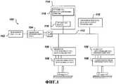
Фиг.1 представляет собой блок-схему приводимого в качестве примера локомотива 100 предшествующего уровня техники. В частности, Фиг.1 в общем виде отражает типичный дизель-электровоз, относящийся к предшествующему уровню техники, такой как, например, АС6000 или АС4400, оба из которых могут быть приобретены у General Electric Transportation Systems. Как показано на Фиг.1, локомотив 100 включает в себя дизельный двигатель 102, приводящий в действие генератор переменного тока/выпрямитель 104. Как широко известно в данной области техники, генератор переменного тока/выпрямитель 104 подает электрическую мощность постоянного тока в инвертор 106, который преобразует электрическую мощность постоянного тока в переменный ток в форме, пригодной для использования тяговым электродвигателем 108, установленным на платформе под корпусом основного двигателя. Одна из распространенных конфигураций локомотива включает по одной паре инвертор/тяговый электродвигатель на ось. В иллюстративных целях на Фиг.1 проиллюстрированы два инвертора 106.Figure 1 is a block diagram of an
Строго говоря, инвертор преобразует мощность постоянного тока в мощность переменного тока. Выпрямитель преобразует мощность переменного тока в мощность постоянного тока. Для обозначения инверторов и выпрямителей также иногда используется термин «преобразователь». Подводимая таким образом электрическая мощность может именоваться мощностью первичного двигателя (или первичной электрической мощностью), а генератор переменного тока/выпрямитель 104 может именоваться источником мощности первичного двигателя. При типичном применении дизель-электровоза переменного тока электрическая мощность переменного тока из генератора переменного тока сначала выпрямляют (преобразуют в постоянный ток). Выпрямленный переменный ток после этого инвертируют (например, с использованием силовой электронной аппаратуры, такой как биполярные транзисторы с изолированным затвором (IGBT) или тиристоры, действующие в качестве широтно-импульсных модуляторов), для того чтобы обеспечить подходящую форму мощности переменного тока для соответствующего тягового электродвигателя 108.Strictly speaking, an inverter converts DC power to AC power. A rectifier converts AC power to DC power. The term "converter" is also sometimes used to refer to inverters and rectifiers. The electrical power thus supplied may be referred to as the power of the prime mover (or primary electrical power), and the alternator /
Как известно в данной области техники, тяговые электродвигатели 108 обеспечивают тяговое усилие для перемещения локомотива 100 и любых других транспортных средств, таких как грузовые вагоны, прицепленные к локомотиву 100. Такие тяговые электродвигатели 108 могут представлять собой электрические двигатели переменного тока или постоянного тока. При использовании тяговых электродвигателей постоянного тока ток на выходе генератора переменного тока обычно выпрямляют с тем, чтобы обеспечить надлежащую мощность постоянного тока. При использовании тяговых электродвигателей переменного тока ток на выходе генератора переменного тока обычно выпрямляют, преобразуя его в постоянный ток, и после этого инвертируют в трехфазный переменный ток, прежде чем подать на тяговые электродвигатели 108.As is known in the art,
Тяговые электродвигатели 108 обеспечивают также усилие торможения для управления скоростью или для замедления локомотива 100. Это обычно именуется динамическим торможением и широко известно в данной области техники. Если дать упрощенное описание, то когда тяговый электродвигатель не нужен для обеспечения движущей силы, он может быть переконфигурирован (посредством силовых переключающих устройств) таким образом, что электродвигатель действует как генератор. Сконфигурированный таким образом тяговый электродвигатель генерирует электрическую энергию, что имеет своим результатом замедление локомотива. В локомотивах предшествующего уровня техники, таких как локомотив, проиллюстрированный на Фиг.1, энергия, сгенерированная в режиме динамического торможения, обычно передается на элементы 110 реостата, установленные на корпусе локомотива. Таким образом, энергия динамического торможения преобразуется в тепло и рассеивается из системы. Иначе говоря, энергия, сгенерированная в режиме динамического торможения, обычно теряется.
Следует отметить, что в типичном локомотиве постоянного тока согласно предшествующему уровню техники элементы реостата динамического торможения соединены с тяговыми электродвигателями. Однако в типичном локомотиве переменного тока согласно предшествующему уровню техники элементы реостата динамического торможения соединены с тяговой электрической шиной 112 постоянного тока, поскольку каждый тяговый электродвигатель обычно соединен с этой шиной посредством связанного с ним инвертора (см. Фиг.1).It should be noted that in a typical direct current locomotive according to the prior art, dynamic braking rheostat elements are connected to traction motors. However, in a typical AC locomotive according to the prior art, the elements of the dynamic braking rheostat are connected to the DC traction
Для того чтобы избежать потери этой сгенерированной энергии, были разработаны системы локомотивов с гибридной энергетической установкой, включающие в себя системы 114 поглощения и аккумулирования энергии, предназначенные для поглощения и регенерации по меньшей мере части электрической энергии динамического торможения, сгенерированной при работе тяговых электродвигателей локомотива в режиме динамического торможения. Система 114 поглощения и аккумулирования энергии не только поглощает и аккумулирует энергию, сгенерированную в режиме динамического торможения локомотива, но и выдает аккумулированную энергию для содействия тяговому усилию локомотива (то есть чтобы дополнить и/или заменить собой мощность первичного двигателя). Предпочтительно система 114 поглощения и аккумулирования энергии включает в себя по меньшей мере одну из следующих подсистем 116 аккумулирования, предназначенных для аккумулирования электрической энергии, сгенерированной во время режима динамического торможения: подсистему батареи, подсистему маховика или подсистему сверхъемкого конденсатора и преобразователь 118. Возможны и другие подсистемы аккумулирования. Это аккумулирование и повторное использование энергии улучшает рабочие характеристики (эффективность использования топлива, тяговую мощность, выбросы в атмосферу) локомотива. Приводимые в качестве примера гибридные локомотив и внедорожные транспортные средства и системы описаны в патентах США №№ 6591758, 6612245, 6612246 и 6615118 и в заявках на патент США №№ 10/378335, 10/378431 и 10/435261, права на которые принадлежат правообладателю раскрываемого здесь изобретения и содержимое которых включено сюда посредством ссылки.In order to avoid the loss of this generated energy, locomotive systems with a hybrid power plant have been developed, including energy absorption and
Эти транспортные средства должны работать в широком диапазоне условий окружающей среды, включая колебания температуры. Типичный диапазон температуры окружающей среды составляет от -40°С до +50°С, при этом в некоторых областях применения он расширяется до -50°С и +60°С. Одно из устройств 116 аккумулирования энергии, используемых в таких транспортных средствах, представляет собой аккумуляторные батареи различных типов, например свинцово-кислотные, никель-кадмиевые, литий-ионные, никель-металл-гидридные и т.д. Рабочие характеристики аккумуляторной батареи сильно зависят от ее внутренней температуры. Например, никель-кадмиевая батарея требует снижения номинальных рабочих параметров в случае, если температура этой батареи выше 40°С или если она ниже 0°С, и требует значительного (возможно, что почти функционально неприемлемого) снижения номинальных рабочих параметров при температуре ниже -20°С и выше 55°С. Поскольку значительная часть работы локомотива приходится на этот диапазон, то требуется значительно увеличивать размер батареи или радикальным образом ограничивать ее использование во время работы при этой температуре. Кроме того, это оказывает негативное воздействие на срок службы батареи.These vehicles must operate in a wide range of environmental conditions, including temperature fluctuations. A typical ambient temperature range is from -40 ° C to + 50 ° C, while in some applications it expands to -50 ° C and + 60 ° C. One of the
Аналогичным образом другие типы аккумуляторных батарей имеют различную работоспособность в зависимости от температуры. Эти батареи обычно охлаждаются посредством принудительно подаваемого воздуха, а иногда посредством охлаждения жидкостью (например, посредством систем жидкостного охлаждения), а сама жидкость впоследствии охлаждается воздухом. Поскольку диапазон температуры окружающего воздуха слишком широк для того, чтобы эксплуатировать аккумуляторные батареи при их оптимальных рабочих характеристиках, то требуется либо кондиционирование охлаждающего воздуха, либо корректировка рабочих характеристик, например снижение номинальных рабочих параметров батареи. Во время работы при низкой температуре воздух перед охлаждением батареи необходимо нагревать, чтобы предотвратить слишком низкое падение температуры батареи или необходимость снижения номинальных рабочих параметров. В дополнение к этому, для того чтобы поток охлаждающего воздуха оказывал охлаждающее действие на аккумуляторную батарею гибридной энергетической установки непосредственно или через промежуточный контур с жидким теплоносителем, температура потока воздуха должна быть ниже, чем температура батареи. Поскольку диапазон температур окружающего воздуха, в котором должны работать локомотивы и другие внедорожные транспортные средства, может достигать 60°С, то для большинства технологий аккумулирования энергии работа гибридного транспортного средства при высокой температуре окружающей среды представляет серьезную проблему. Требуется либо предварительно охлаждать охлаждающий воздух, либо снижать номинальную рабочую характеристику батареи. Эти операции и системы охлаждения/нагрева являются сложными и добавляют издержки в соотношении массы/размера/затрат.Similarly, other types of batteries have different performance depending on the temperature. These batteries are usually cooled by forced air, and sometimes by liquid cooling (for example, by means of liquid cooling systems), and the liquid itself is subsequently cooled by air. Since the ambient temperature range is too wide to operate the batteries at their optimum performance, either cooling air conditioning or performance adjustment is required, such as lowering the battery’s rated performance. During low temperature operation, the air must be heated before cooling the battery to prevent the battery temperature from dropping too low or the need to reduce the rated operating parameters. In addition, in order for the cooling air flow to have a cooling effect on the battery of the hybrid power plant directly or through an intermediate circuit with a liquid coolant, the temperature of the air flow must be lower than the temperature of the battery. Since the ambient temperature range in which locomotives and other off-road vehicles should operate can reach 60 ° C, for most energy storage technologies, operating a hybrid vehicle at high ambient temperatures is a serious problem. You must either pre-cool the cooling air, or reduce the rated performance of the battery. These operations and cooling / heating systems are complex and add costs in a mass / size / cost ratio.
Следовательно, имеется потребность в высокотемпературной батарее и системе для локомотивов и внедорожных транспортных средств, предназначенных для работы в широком диапазоне температур, которые не требуют предварительного охлаждения охлаждающего воздуха, и при этом упомянутая система способна управлять температурой батареи так, чтобы обеспечивать оптимальные рабочие характеристики.Therefore, there is a need for a high-temperature battery and system for locomotives and off-road vehicles designed to operate in a wide range of temperatures that do not require cooling air pre-cooling, while the said system is able to control the temperature of the battery so as to provide optimal performance.
Краткое описание раскрываемого изобретенияSummary of Disclosed Invention
Предлагается система электрической аккумуляторной батареи, установленная на внедорожном транспортном средстве с гибридной энергетической установкой, включающем в себя колеса для опоры и перемещения транспортного средства, генератор электрической мощности и тяговые электродвигатели для привода этих колес, причем электрическая мощность, сгенерированная на этом транспортном средстве, аккумулируется в выбранные моменты времени в системе электрической аккумуляторной батареи и выдается из системы электрической аккумуляторной батареи для передачи тяговым электродвигателям с целью приведения в движение этого транспортного средства, причем эти транспортное средство и система батареи подвергаются воздействию некоторого диапазона условий окружающей среды. Система аккумуляторной батареи включает в себя по меньшей мере одну батарею для аккумулирования и высвобождения электрической мощности, причем эта по меньшей мере одна батарея создает внутреннюю рабочую температуру батареи, которая превышает самую высокую температуру окружающей это транспортное средство среды.An electric battery system mounted on an off-road vehicle with a hybrid power plant is proposed, including wheels for supporting and moving the vehicle, an electric power generator and traction motors for driving these wheels, the electric power generated on this vehicle being accumulated in selected times in the electric battery system and issued from the electric battery system for transmission to traction motors in order to propel this vehicle, the vehicle and battery system being exposed to a range of environmental conditions. The battery system includes at least one battery for storing and releasing electrical power, and this at least one battery creates an internal battery operating temperature that exceeds the highest ambient temperature of the vehicle.
В другом аспекте раскрываемого здесь изобретения предлагается система электрической аккумуляторной батареи, установленная на внедорожном транспортном средстве с гибридной энергетической установкой, включающем в себя колеса для опоры и перемещения транспортного средства, генератор электрической мощности и тяговые электродвигатели для привода этих колес, причем электрическая мощность, сгенерированная на этом транспортном средстве, аккумулируется в выбранные моменты времени в системе электрической аккумуляторной батареи и выдается из системы электрической аккумуляторной батареи для передачи тяговым электродвигателям с целью приведения в движение этого транспортного средства, причем эти транспортное средство и система батареи подвергаются воздействию некоторого диапазона условий окружающей среды, при этом система электрической аккумуляторной батареи включает в себя по меньшей мере одну батарею для аккумулирования и высвобождения электрической мощности, причем эта батарея работает при некоторой внутренней температуре батареи для эффективного аккумулирования и высвобождения электрической мощности, представляющей собой эффективную температуру батареи, которая выше любой из температур окружающей транспортное средство и систему батареи среды, и при этом батарея охлаждается до более низкой температуры, чем ее эффективная внутренняя рабочая температура, когда транспортное средство не находится в эксплуатации в течение длительного периода времени; контрольно-измерительный прибор для измерения параметра, являющегося показателем внутренней температуры батареи; и контроллер для управления нагревом батареи вновь до ее эффективной температуры, когда внутренняя температура батареи падает ниже заранее заданного уровня, так что батарея остается готовой к эффективной работе при возвращении транспортного средства к работе.In another aspect of the invention disclosed herein, there is provided an electric battery system mounted on an off-road vehicle with a hybrid power plant including wheels for supporting and moving a vehicle, an electric power generator and traction motors for driving these wheels, the electric power generated on this vehicle, accumulates at selected times in the electric battery system and is issued from an electric storage battery system for transmitting to traction electric motors to drive this vehicle, the vehicle and the battery system being exposed to a certain range of environmental conditions, wherein the electric storage battery system includes at least one storage battery and release of electrical power, and this battery operates at a certain internal temperature of the battery for efficient storage and the release of electrical power, which is the effective temperature of the battery, which is higher than any temperature surrounding the vehicle and the battery system of the environment, and the battery is cooled to a lower temperature than its effective internal operating temperature when the vehicle is not in use for a long period of time; a control device for measuring a parameter that is an indicator of the internal temperature of the battery; and a controller for controlling the heating of the battery again to its effective temperature when the internal temperature of the battery falls below a predetermined level, so that the battery remains ready for efficient operation when the vehicle returns to operation.
Краткое описание чертежейBrief Description of the Drawings
Вышеупомянутые и другие аспекты, признаки и преимущества раскрываемого здесь изобретения станут более понятными в свете нижеследующего подробного описания при его рассмотрении совместно с прилагаемыми чертежами, на которых:The above and other aspects, features and advantages of the invention disclosed herein will become more apparent in light of the following detailed description when considered in conjunction with the accompanying drawings, in which:
Фиг.1 - блок-схема традиционной гибридной двигательной установки локомотива;Figure 1 is a block diagram of a conventional hybrid locomotive propulsion system;
Фиг.2 - блок-схема варианта реализации гибридной энергетической двигательной установки по настоящему изобретению;Figure 2 is a block diagram of an embodiment of a hybrid power propulsion system of the present invention;
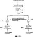
Фиг.3 - блок-схема системы управления батареей;Figure 3 is a block diagram of a battery management system;
Фиг.4А - блок-схема традиционной системы жидкостного охлаждения двигателя;4A is a block diagram of a conventional liquid engine cooling system;
Фиг.4В-4D - блок-схемы систем жидкостного охлаждения в соответствии с принципами настоящего изобретения;4B-4D are block diagrams of liquid cooling systems in accordance with the principles of the present invention;
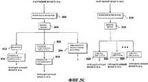
Фиг.5А - блок-схема традиционной системы воздушного охлаждения;5A is a block diagram of a conventional air cooling system;
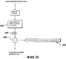
Фиг.5В-5I - блок-схемы систем воздушного охлаждения в соответствии с принципами настоящего изобретения.5B-5I are block diagrams of air cooling systems in accordance with the principles of the present invention.
Подробное описание раскрываемого изобретенияDetailed description of the disclosed invention
Предпочтительные варианты реализации настоящего изобретения будут описаны ниже со ссылкой на прилагаемые чертежи. В нижеследующем описании хорошо известные функции или конструкции подробно не описываются для того, чтобы избежать «затемнения» сути раскрываемого здесь изобретения ненужной детализацией.Preferred embodiments of the present invention will be described below with reference to the accompanying drawings. In the following description, well-known functions or constructions are not described in detail in order to avoid "dimming" the essence of the invention disclosed herein by unnecessary detail.
Предлагаются батарея, система и способ управления батареей, предназначенные для использования в локомотивах и больших внедорожных транспортных средствах. В системе и способе по настоящему изобретению используются аккумуляторные батареи, которые работают при высоких внутренних температурах, например натрий-никель-хлоридная батарея, которая работает при температурах свыше 270°С, или в качестве другого примера натрий-серная батарея, которая может работать при температурах свыше 350°С. Эти батареи используют для аккумулирования и высвобождения электрической энергии или мощности химическую реакцию, например экзотермическую реакцию. Эта экзотермическая реакция создает внутреннюю рабочую температуру, которая не зависит от самой высокой температуры окружающей транспортное средство среды и превышает эту самую высокую температуру. При использовании высокотемпературной батареи в гибридном внедорожном транспортном средстве не требуется никакого предварительного охлаждения охлаждающего воздуха, необходимого для аккумуляторной батареи гибридной энергетической установки (даже в условиях самой высокой температуры окружающего воздуха). Традиционные конструкции батарей либо требуют снижения номинальных рабочих параметров в условиях самой высокой температуры окружающего воздуха, либо требуют некоторого предварительного охлаждения воздуха, используемого для отвода тепла, в условиях самой высокой температуры окружающего воздуха. Традиционные батареи способны работать в течение коротких периодов времени при температурах порядка 50°С, но для того чтобы соответствовать прогнозам срока службы изготовителя, они должны эксплуатироваться при температурах менее примерно 35°С.A battery, a system and a battery control method for use in locomotives and large off-road vehicles are provided. The system and method of the present invention uses rechargeable batteries that operate at high internal temperatures, for example, a sodium-nickel-chloride battery that operates at temperatures above 270 ° C, or as another example, a sodium-sulfur battery that can operate at temperatures over 350 ° C. These batteries use a chemical reaction, such as an exothermic reaction, to store and release electrical energy or power. This exothermic reaction creates an internal operating temperature that is independent of the highest ambient temperature of the vehicle and exceeds this highest temperature. When using a high-temperature battery in a hybrid off-road vehicle, no pre-cooling of the cooling air required for the battery of the hybrid power plant (even at the highest ambient temperature) is required. Conventional battery designs either require a reduction in nominal operating parameters under the highest ambient temperature, or require some pre-cooling of the air used to remove heat under the highest ambient temperature. Conventional batteries are able to operate for short periods at temperatures of the order of 50 ° C, but in order to meet the manufacturer's life expectancy, they must be operated at temperatures of less than about 35 ° C.
Даже несмотря на то что эти высокотемпературные батареи нуждаются в начальном нагреве, пока они работают, батареи будут сохранять высокую температуру. Если эти батареи находятся в работе, они нуждаются в охлаждении. Любая батарея, которая работает при температуре, превышающей температуру окружающей локомотив среды, может эффективно охлаждаться с помощью имеющегося вокруг окружающего охлаждающего воздуха либо непосредственно, либо опосредованно через поверхность раздела с жидкой или теплоотводящей средой, а следовательно, окружающий воздух не требует никакого предварительного охлаждения. Преимущество состоит в том, что в диапазоне высоких рабочих температур не требуется никакого охлаждения воздуха или жидкости (например, теплоносителя) и в то же самое время не требуется снижать номинальные рабочие параметры батареи.Even though these high-temperature batteries need initial heating while they are running, the batteries will retain high temperature. If these batteries are in operation, they need cooling. Any battery that operates at a temperature higher than the temperature of the environment surrounding the locomotive can be effectively cooled using the surrounding cooling air, either directly or indirectly through the interface with a liquid or heat sink, and therefore, the surrounding air does not require any pre-cooling. The advantage is that in the range of high operating temperatures no cooling of air or liquid (for example, coolant) is required and at the same time it is not necessary to reduce the nominal operating parameters of the battery.
Охлаждающая среда и схема/система охлаждения, которые используются в сочетании с системой управления батареей по настоящему изобретению, интегрированы в системы транспортного средства. Поскольку охлаждение батареи требуется (обычно) только тогда, когда транспортное средство генерирует мощность (например, в двигательном режиме, режиме торможения), и поскольку во время данного периода также задействованы другие тяговые и управляющие функции, то потребности в охлаждении тяговой/вспомогательной системы могут быть объединены. Например, охлаждающий воздух может быть подан от охлаждающего вентилятора тягового электродвигателя. Поскольку батарея работает при высоких температурах (250-350°С), то батарея может охлаждаться подогретым воздухом (то есть воздухом, который охладил другие конструктивные элементы, такие как силовая электронная аппаратура, тяговый генератор переменного тока, тяговые электродвигатели, радиатор, вспомогательное оборудование и т.д.) и, следовательно, система охлаждения может быть упрощена. Также возможно объединить охлаждение батареи с водяной системой радиатора двигателя, используя при этом воду в качестве охлаждающей среды. Ниже будут описаны разнообразные возможные системы воздушно-водяного охлаждения.The cooling medium and the cooling circuit / system, which are used in combination with the battery management system of the present invention, are integrated into the vehicle systems. Since battery cooling is required (usually) only when the vehicle generates power (for example, in engine mode, braking mode), and since other traction and control functions are also involved during this period, there may be a need for cooling of the traction / auxiliary system combined. For example, cooling air may be supplied from a cooling fan of the traction motor. Since the battery operates at high temperatures (250-350 ° C), the battery can be cooled with heated air (i.e. air that has cooled other components, such as power electronic equipment, traction alternator, traction motors, radiator, auxiliary equipment and etc.) and therefore the cooling system can be simplified. It is also possible to combine the cooling of the battery with the water system of the engine radiator, using water as a cooling medium. A variety of possible air-water cooling systems will be described below.
Фиг.2 является представленной на системном уровне блок-схемой, которая иллюстрирует аспекты системы 200 управления батареей по настоящему изобретению. В частности, Фиг.2 иллюстрирует систему 200 управления батареей, подходящую для использования с гибридной энергетической установкой локомотива, такой как гибридная энергетическая установка 100 локомотива, показанная на Фиг.1. Однако следует понимать, что система 200 управления батареей, проиллюстрированная на Фиг.2, также подходит для использования с другими большими внедорожными транспортными средствами. Такие транспортные средства включают в свое число, например, большие экскаваторы, карьерные самосвалы и тому подобное. В качестве дополнительного примера отметим, что в таких больших карьерных самосвалах могут использоваться мотор-колеса, такие как мотор-колесо GEB23.TM.AC, использующее систему привода GE150AC.TM (оба из которых могут быть приобретены у правообладателя настоящего изобретения). Следовательно, хотя Фиг.2, в общем, описана в отношении установки локомотива, проиллюстрированная на ней система 200 управления батареей не должна рассматриваться как ограниченная применениями в локомотивах.FIG. 2 is a system block diagram that illustrates aspects of the
Как проиллюстрировано на Фиг.2, дизельный двигатель 102 приводит в действие источник 104 мощности первичного двигателя (например, преобразователь в виде генератора переменного тока/выпрямителя). Предпочтительно источник 104 мощности первичного двигателя подает мощность постоянного тока на инвертор 106, который подводит мощность трехфазного переменного тока к тяговому электродвигателю 108 локомотива. Однако следует понимать, что система 200, проиллюстрированная на Фиг.2, может быть изменена также таким образом, чтобы также функционировать с тяговыми электродвигателями постоянного тока. Предпочтительно имеется множество тяговых электродвигателей (например, по одному на ось), и каждая ось связана с множеством колес 109 локомотива. Иными словами, каждый тяговый электродвигатель локомотива предпочтительно включает в себя вращающийся вал, соединенный со связанной с ним осью для обеспечения тягового усилия на колеса. Таким образом, каждый тяговый электродвигатель 108 локомотива обеспечивает необходимую движущую силу связанному с ним множеству колес 109 локомотива, вызывая перемещение локомотива.As illustrated in FIG. 2, a
При эксплуатации тяговых электродвигателей 108 в режиме динамического торможения по меньшей мере часть сгенерированной электрической мощности направляется в носитель для аккумулирования энергии, такой как аккумуляторная батарея 204. В той мере, в которой эта батарея 204 неспособна принять и/или аккумулировать всю энергию динамического торможения, избыточная энергия предпочтительно направляется в элементы 110 реостата торможения для рассеивания в виде тепловой энергии. Кроме того, во время периодов, когда двигатель 102 эксплуатируется таким образом, что он обеспечивает больше энергии, чем необходимо для приведения в действие тяговых электродвигателей 108, избыточная мощность (также именуемая избыточной электрической мощностью первичного двигателя) может необязательно быть аккумулирована в батарее 204. Соответственно, батарея 204 может заряжаться в моменты времени, отличные от тех, когда тяговые электродвигатели 108 работают в режиме динамического торможения. Этот аспект системы проиллюстрирован на Фиг.2 штрихпунктирной линией 201, где инвертор 106 управляется как преобразователь постоянного тока в постоянный ток (что не проиллюстрировано на Фиг.2).When the
Батарея 204 по Фиг.2 предпочтительно сконструирована и выполнена с возможностью селективного увеличения мощности, выдаваемой тяговым электродвигателям 108, или, необязательно, запитывания отдельных тяговых электродвигателей, связанных с отдельным энергетическим тендерным прицепом или грузовым вагоном. Такая мощность может именоваться вторичной электрической мощностью и получается из электрической энергии, аккумулированной в батарее 204. Таким образом, система 200, проиллюстрированная на Фиг.2, пригодна для использования в сочетании с локомотивом, имеющим бортовой носитель для аккумулирования энергии, и/или с отдельным энергетическим тендерным прицепом.The
Система 200 включает в себя систему 202 управления батареей для управления разнообразными операциями, связанными с батареей 204, такими как управление температурой батареи и/или зарядкой/разрядкой батареи. Фиг.2 также иллюстрирует дополнительный источник 203 энергии, который предпочтительно управляется системой 202 управления батареей. Этот дополнительный источник 203 энергии может представлять собой второй двигатель (например, заряжающий двигатель или другой локомотив) или совершенно отдельный источник мощности (например, расположенный рядом с путями источник мощности, такой как зарядное устройство для батареи), предназначенный для зарядки батареи 204. В одном предпочтительном варианте реализации дополнительный источник 203 энергии соединен с тяговой электрической шиной (не проиллюстрированной на Фиг.2), которая также передает первичную электрическую мощность от источника 104 мощности первичного двигателя.
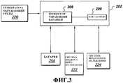
Как проиллюстрировано на Фиг.3, система 202 управления батареей предпочтительно включает в себя процессор 206 управления батареей и базу 208 данных. Процессор 206 управления батареей определяет различные условия окружающей среды, например температуру окружающей батарею среды, и использует эту информацию об окружающей среде для нахождения данных в этой базе 208 данных с тем, чтобы оценить внутреннюю температуру батареи. Следует понимать, что такая содержащаяся в базе данных информация могла бы предоставляться различными источниками, включая бортовую базу данных, связанную с процессором 206; систему связи (например, систему беспроводной связи), предоставляющую информацию из центрального источника; данные, вводимые вручную оператором; данные, передаваемые одним или более расположенными рядом с путями сигнальными устройствами; сочетание таких источников и тому подобное. Наконец, и другая информация о транспортном средстве, такая как размер и масса транспортного средства, допустимая мощность, связанная с первичным двигателем, показатели коэффициента полезного действия, текущая и ожидаемая скорость, текущая и ожидаемая электрическая нагрузка и тому подобное, может быть включена в базу данных (или передана в реальном или близком к реальному масштабе времени) и использована процессором 206 управления батареей.As illustrated in FIG. 3, the
Внутренняя температура батареи используется для разнообразных решений по управлению, включая пределы зарядки и разряда, и для принятия решения о том, запускать ли вновь двигатель для повторного нагрева или позволить ей замерзнуть и т.д. Обычно измерять внутреннюю температуру батареи бывает сложно из-за стоимости и сложности датчика. Поэтому процессор 206 управления батареей по настоящему изобретению оценивает внутреннюю температуру батареи, используя тепловые модели, хранящиеся в базе 208 данных. Эти тепловые модели основываются на разнообразных входных данных, включая возможную температуру корпуса батареи, температуру/давление окружающей среды, временную диаграмму тока заряда/разряда батареи и временную диаграмму работы вентилятора(ов) охлаждения батареи (температуру/расход теплоносителя). Эти входные данные используются для оценки внутренней температуры элементов аккумуляторной батареи внутри батарейного модуля. Спрогнозированная внутренняя температура батарей от всех батарейных модулей может быть использована для сравнения с измерениями истинной температуры внутри по меньшей мере одного выбранного модуля для сравнения с тепловой моделью. Если спрогнозированная температура отличается от измеренной температуры на ХХ градусов Цельсия, то может быть предпринято соответствующее действие (как то, снижение номинальных рабочих параметров, сообщение оператору, плановое техническое обслуживание и т.д.). Если спрогнозированная температура отличается от измеренных(ой) температур(ы) на YY градусов Цельсия (где YY>ХХ, например, значение ХХ могло бы составлять приблизительно 5 градусов Цельсия, тогда как значение YY могло бы составлять приблизительно 10 градусов Цельсия), то могут быть предприняты дальнейшие ограничительные шаги. Это могло бы включать в себя блокирование работы батареи. Тепловая модель батареи использует измеренные снаружи значения тока батареи, напряжение батареи плюс состояние заряда (SOC), которое вычисляется на основе суммарного интегрированного заряда батареи в ампер-часах. Кроме того, в качестве части этой модели для прогнозирования текущей температуры батареи используется предыстория и тенденция использования батареи в последнее время во время заряда и разряда батареи в этом транспортном средстве. Помимо этого, для определения температурной модели и/или сопротивления при конкретном состоянии заряда может быть использовано сопротивление на клеммах батареи. Для разработки начальной модели используются характеристики, основанные на испытаниях элементов батареи в лаборатории при различных температурах. Результаты, полученные на начальных тепловых моделях, сравниваются с истинной измеренной температурой батареи в течение представительных циклов заряда и разряда. На основе результатов лабораторных испытаний производится уточнение моделей.The internal temperature of the battery is used for a variety of control decisions, including charging and discharging limits, and for deciding whether to start the engine again to reheat or allow it to freeze, etc. It is usually difficult to measure the internal temperature of the battery due to the cost and complexity of the sensor. Therefore, the
После того как тепловая модель для батареи определена, процессор 206 управления батареей получает разнообразные параметры системы, например, из системы 222 жидкостного охлаждения и системы 224 воздушного охлаждения и управляет различными устройствами в этих системах так, чтобы управлять температурой батареи 204. Охлаждающие среды могут управляться таким образом, что в системах с множественными параллельными блоками батарей температура каждого компонента поддерживается в заранее заданных пределах. Обычно для получения мощностей разрядки и перезарядки, достаточных для применений в локомотивах и внедорожных транспортных средствах, требуется параллельная работа отдельных блоков батарей. Это могло бы быть достигнуто посредством разнообразных технологий, включая независимые регуляторы системы температуры/охлаждения, которые будут описаны ниже.After the thermal model for the battery is determined, the
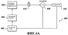
На Фиг.4А проиллюстрирована традиционная жидкостная система охлаждения двигателя. Такая система обычно включает в себя водяной бак 402 для размещения воды или другой охлаждающей среды, например теплоносителя, водяной насос 404 для прокачки теплоносителя по системе и водяную рубашку 406 двигателя, которая охлаждает двигатель за счет циркуляции теплоносителя вокруг двигателя. Датчик 412 температуры, расположенный в отводящей линии водяной рубашки, будет определять, находится ли теплоноситель выше заранее заданной температуры, и если это так, то будет устанавливать клапан 408 в положение циркуляции теплоносителя через радиатор 410. В ином случае теплоносителю будет дана возможность течь напрямую назад в водяной бак 402.4A illustrates a conventional liquid engine cooling system. Such a system typically includes a
Фиг.4В-4D иллюстрируют системы жидкостного охлаждения в соответствии с принципами настоящего изобретения. В этих системах жидкостного охлаждения высокотемпературная батарея 204 может включать в себя водяную рубашку для охлаждения или понижения температуры батареи. Как показано на Фиг.4В, после того как процессор 206 управления батареей определил внутреннюю температуру батареи, процессор 206 снимает с датчика 412 показания температуры теплоносителя. Если батарея 204 нуждается в охлаждении, то процессор посылает на клапаны 408, 414 соответственно первый и второй управляющие сигналы для того, чтобы отвести часть потока теплоносителя к батарее. Следует понимать, что клапаны 408 и 412 могут представлять собой единый трехходовой клапан. Когда батарея 204 достигла удовлетворительной температуры, процессор 206 управляет клапанами 408 и 414 таким образом, чтобы весь поток теплоносителя проходил через радиатор 410.4B-4D illustrate liquid cooling systems in accordance with the principles of the present invention. In these liquid cooling systems, the
Фиг.4С представляет собой другой вариант реализации системы жидкостного охлаждения, используемой в сочетании с системой управления батареей по настоящему изобретению. Как показано на Фиг.4С, теплоноситель отводится с помощью клапана 414 к батарее 204 до охлаждения двигателя посредством водяной рубашки 406 двигателя. При этом теплоноситель, соприкасающийся с батареей, будет иметь более низкую температуру, чем теплоноситель, показанный на Фиг.4В, и способен обеспечить более высокую степень охлаждения. Кроме того, жидкостная система, показанная на Фиг.4С, будет включать в себя датчик 416 температуры для использования процессором 206 с целью определения того, имеется ли доступный теплоноситель для охлаждения батареи.4C is another embodiment of a liquid cooling system used in combination with the battery management system of the present invention. As shown in FIG. 4C, the coolant is vented via
Фиг.4D представляет собой другой вариант реализации системы жидкостного охлаждения, используемой в сочетании с системой управления батареей по настоящему изобретению. В этом случае предусмотрен второй водяной насос 418 с тем, чтобы обеспечивать батарее 204 дополнительную емкость. Датчик 420 температуры будет передавать сигнал температуры процессору 206, что позволяет процессору определить, имеется ли доступный теплоноситель для охлаждения. Датчик 422 температуры будет измерять температуру теплоносителя после его отвода от батареи 204, и процессор будет использовать эту температуру, чтобы определить, нуждается ли этот отведенный теплоноситель в охлаждении посредством радиатора 410 или может быть отправлен назад в водяной бак 402. На основе этого определения процессор 206 управляет установкой клапана 414 в соответствующее положение.Fig. 4D is another embodiment of a liquid cooling system used in combination with the battery management system of the present invention. In this case, a
На Фиг.5А проиллюстрирована традиционная система принудительного воздушного охлаждения. Такая система обычно включает в себя множество воздуховодов 502 для направления наружного, взятого из окружающей среды или кондиционированного воздуха к различным конструктивным элементам системы 500. Вентилятор 504 всасывает наружный воздух (ОА) через множество решеток и фильтров 506 и подает этот наружный воздух к различным конструктивным элементам системы, таким как силовая электронная аппаратура 508, генератор 510 переменного тока и т.д. для охлаждения этих конструктивных элементов. При подаче наружного воздуха в кабину оператора или к чувствительной электронной аппаратуре 514 могут быть использованы дополнительные фильтры 512. Помимо этого, дополнительные вентиляторы 518 с соответствующими решетками и фильтрами подают воздух для непосредственного охлаждения электродвигателей 520.FIG. 5A illustrates a conventional forced air cooling system. Such a system typically includes a plurality of
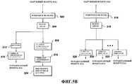
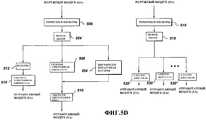
Фиг.5В-5I иллюстрируют системы принудительного воздушного охлаждения в соответствии с принципами настоящего изобретения. На Фиг.5В воздух выводится из выпускной трубы генератора 510 переменного тока к батарее 204. На Фиг.5С воздух выводится со стороны выпуска вентилятора 504 непосредственно к батарее 204, а на Фиг.5D воздух, выходящий от батареи 204, регенерируется и подается назад для охлаждения генератора 510 переменного тока. На Фиг.5Е батарея 204 обдувается воздухом на его пути между силовой электронной аппаратурой 508 и генератором 510 переменного тока, а на Фиг.5F батарея 204 получает воздух, выходящий от силовой электронной аппаратуры, как и на Фиг.5Е, но после охлаждения батареи просто выбрасывает этот воздух.5B-5I illustrate forced air cooling systems in accordance with the principles of the present invention. In FIG. 5B, air is discharged from the exhaust pipe of the
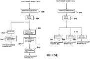
Фиг.5G иллюстрирует конфигурацию, при которой наружный или окружающий воздух подается непосредственно к батареям 204. Эта конфигурация выгодна там, где желательно максимальное охлаждение, например в случаях более теплого климата. Поскольку воздух, поступающий к батареям 204, не является предварительно нагретым, на этих батареях будет достигаться максимальный перепад температур. Аналогичная конфигурация показана на Фиг.5Н. Здесь параллельные прямоугольники батарей получают воздух от единого вентилятора 530 и управляются независимо друг от друга посредством системы управления батареями. Процессор батареи определяет температуру батареи так, как это описано выше, и получает значение температуры выходящего из вентилятора воздуха посредством датчика 532 температуры. На основе температуры батареи и температуры выходящего из вентилятора воздуха, процессор батареи управляет задвижками 534, 536 таким образом, чтобы обеспечить надлежащее количество воздуха для охлаждения батарей.Fig. 5G illustrates a configuration in which outside or ambient air is supplied directly to the
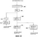
В дополнительном варианте реализации, показанном на Фиг.5I, воздух, нагретый батареей, может быть использован для отопления кабины локомотива. Процессор 206 управления батареей будет получать показания температуры в кабине оператора посредством пространственного датчика 540 температуры и температуры отходящего от батареи воздуха посредством датчика 532 температуры. После этого процессор 206 управления батареей будет определять, может ли отходящий от батареи воздух быть использован для отопления кабины оператора, и если это так, то будет управлять задвижкой 544 таким образом, чтобы отвести отходящий воздух в кабину оператора через надлежащие решетки и фильтры. В качестве альтернативы этот отходящий воздух направляется в теплообменник, соединенный с системой жидкостного отопления, так что не происходит никаких прямых передач воздуха.In a further embodiment, shown in FIG. 5I, air heated by a battery can be used to heat the locomotive cab. The
Следует понимать, что Фиг.5В-5I представляют собой просто приводимые в качестве примера конфигурации систем воздушного охлаждения, используемых в сочетании с системой управления батареей для управления температурой батареи, и что имеется и много других возможных конфигураций. Также следует понимать, что система охлаждения батареи может представлять собой автономную систему жидкостного охлаждения, автономную систему воздушного охлаждения или комбинированную систему жидкостного и воздушного охлаждения.It should be understood that FIGS. 5B-5I are merely exemplary configurations of air cooling systems used in conjunction with a battery management system to control battery temperature, and that there are many other possible configurations. It should also be understood that the battery cooling system may be an autonomous liquid cooling system, an autonomous air cooling system, or a combined liquid and air cooling system.
Внутренняя температура батареи будет также использоваться для управления скоростями заряда и разряда в дополнение к традиционному состоянию заряда (SOC). Если внутренняя температура батареи находится в пределах определенного рабочего диапазона температур, например внутренняя температура > Т1, но < Т2, то процессор управления батареей разрешает разряд батареи при том условии, что напряжение на клеммах батареи и состояние заряда (SOC) выше заранее заданных пределов. Аналогичным образом, если внутренняя температура > Т3, но < Т4, то процессор управления батареей разрешает ток перезарядки при том условии, что напряжение на клеммах батареи и состояние заряда (SOC) ниже заранее заданных пределов. Один пример этого состоит в том, чтобы процессор управления батареей разрешал ее разрядку в случае, если Т1 и Т2 составляют 270°С и 350°С соответственно. В другом примере перезарядка со скоростью вплоть до заранее заданной высокой скорости допускается в случае, если Т3 и Т4 составляют 270°С и 320°С соответственно, а значение SOC меньше чем 70% полного заряда батареи. В еще одном другом примере перезарядка с заранее заданной низкой скоростью допускается в случае, если Т3 и Т4 составляют 270°С и 340°С соответственно, а значение SOC меньше чем 100%. В этих примерах значение SOC вычисляется традиционным образом, включая интегрирование тока батареи с целью определения суммарного заряда в ампер-часах, поступающего в батарею и выходящего из батареи.The internal temperature of the battery will also be used to control charge and discharge rates in addition to the traditional state of charge (SOC). If the internal temperature of the battery is within a certain operating temperature range, for example, the internal temperature> T1 but <T2, then the battery management processor allows the battery to be discharged provided that the voltage at the battery terminals and the state of charge (SOC) are above predetermined limits. Similarly, if the internal temperature is> T3, but <T4, then the battery control processor permits recharge current, provided that the voltage at the battery terminals and the state of charge (SOC) are below predetermined limits. One example of this is for a battery control processor to permit its discharge if T1 and T2 are 270 ° C and 350 ° C, respectively. In another example, recharging at speeds up to a predetermined high speed is allowed if T3 and T4 are 270 ° C and 320 ° C, respectively, and the SOC value is less than 70% of the total battery charge. In yet another example, recharging at a predetermined low speed is allowed if T3 and T4 are 270 ° C and 340 ° C, respectively, and the SOC value is less than 100%. In these examples, the SOC value is calculated in the traditional way, including integrating the battery current to determine the total charge in ampere-hours entering and leaving the battery.
Локомотивы и внедорожные транспортные средства используются в течение значительной части дня/года. Однако во время периодов простоя внутренняя температура батареи должна оставаться выше заранее заданного предела. Система 202 управления батареей по настоящему изобретению будет взаимодействовать с различными подсистемами для обеспечения того, чтобы батарея оставалась теплой, то есть сохраняла температуру выше заранее заданного предела температуры. Если во время периодов, когда двигатель выключен, температура батареи достигает заранее заданного нижнего предела температуры, то система управления батареей может посылать сигнал на повторный запуск двигателя до тех пор, пока батарея не зарядится до определенного высокого состояния заряда, так чтобы батарея могла поддерживаться теплой. Поскольку локомотив обычно простаивает только в течение коротких периодов времени, этот процесс повторного нагрева батареи ожидается редко. Система управления батареей может отдать команду двигателю/генератору переменного тока или вспомогательному источнику 203 мощности предоставить электрическую мощность для заряда батареи, отдать команду двигателю/генератору переменного тока или вспомогательному источнику 203 предоставить электрическую мощность электрическим нагревательным элементам внутри батареи или посредством ряда переключателей может использовать силовые клеммы постоянного тока на самой батарее для запитывания этих электрических нагревательных элементов. Помимо этого, тепло для батареи могут давать горячие выхлопные газы двигателя.Locomotives and off-road vehicles are used for a significant part of the day / year. However, during periods of inactivity, the internal temperature of the battery must remain above a predetermined limit. The
После продолжительного простоя, вызванного незапланированными событиями (например, продолжительного ремонта), батареи могут быть нагреты с использованием внешнего средства. Например, батареи могут поддерживаться горячими за счет внешнего электропитания постоянного/переменного тока при соответствующем управлении посредством процессора управления батареей. В качестве другого примера могут применяться электрические нагревательные элементы, встроенные в батарею, или могут быть использованы нагревательные элементы в самом транспортном средстве, например элементы реостата торможения. В качестве еще одной альтернативы к клеммам батареи может быть приложена электрическая мощность таким образом, чтобы создать множество внутренних потерь в батарее, например, посредством высокоскоростной зарядки, возможно, с последующей высокоскоростной разрядкой, которые будут нагревать батарею. Также возможно продлить этот период времени, поддерживая батареи теплыми с помощью изоляции/технологий управления тепловыми процессами/управления температурой теплоносителя, как те, что были описаны выше.After prolonged downtime caused by unplanned events (for example, a lengthy repair), the batteries can be heated using an external means. For example, batteries may be kept hot by external AC / AC power with appropriate control by a battery management processor. As another example, electric heating elements integrated in a battery can be used, or heating elements can be used in the vehicle itself, for example braking rheostat elements. As another alternative, electrical power can be applied to the battery terminals in such a way as to create many internal losses in the battery, for example, by high-speed charging, possibly followed by high-speed discharge, which will heat up the battery. It is also possible to extend this period of time by keeping the batteries warm with insulation / thermal process control / thermal fluid temperature control technologies, such as those described above.
Если во время длительных периодов нерабочего состояния локомотива и высокотемпературных батарей, скажем, при нахождении его на запасных путях, температура батареи может упасть до значения, близкого к температуре замерзания находящегося внутри нее электролита, то процессор 206 управления батареей на основе полученных им переменных параметров, например температур от датчиков, или введенной оператором информации, например времени простоя, будет принимать решение о том, использовать ли внутреннюю энергию батареи для нагрева батареи или позволить батарее замерзнуть. Если известно, что локомотив не будет работать раньше, чем через заданное время, такое как 7 дней, то процессор управления батареей позволит батарее замерзнуть. Если ожидается, что локомотив заработает ранее, чем через заданное время, то процессор управления батареей обеспечит возможность, например, того, чтобы дополнительный источник 203 энергии осуществлял электрический нагрев батарей для поддержания их при рабочей температуре.If during long periods of non-working condition of a locomotive and high-temperature batteries, for example, when it is on the siding, the temperature of the battery can drop to a value close to the freezing temperature of the electrolyte inside it, then the
Хотя раскрываемое здесь изобретение было проиллюстрировано и описано на типичных вариантах реализации, оно не подразумевается ограниченным приведенными подробностями, поскольку в нем могут быть произведены разнообразные модификации и замены без какого-либо отклонения от сущности настоящего изобретения. Таким образом, специалистам в данной области техники с использованием не более чем рутинного экспериментирования могут прийти на ум дополнительные модификации и эквиваленты настоящего изобретения, раскрытого в данном документе, и все такие модификации и эквиваленты полагаются находящимися в рамках сущности и объема раскрываемого изобретения, определенных нижеследующей формулой изобретения.Although the invention disclosed herein has been illustrated and described in typical embodiments, it is not intended to be limited by the details given, since various modifications and substitutions can be made therein without departing from the gist of the present invention. Thus, those skilled in the art using no more than routine experimentation may come to mind additional modifications and equivalents of the present invention disclosed herein, and all such modifications and equivalents are deemed to be within the spirit and scope of the disclosed invention defined by the following claims inventions.
Claims (19)
Translated fromRussianApplications Claiming Priority (2)
| Application Number | Priority Date | Filing Date | Title |
|---|---|---|---|
| US10/884,501 | 2004-07-02 | ||
| US10/884,501US20060001399A1 (en) | 2004-07-02 | 2004-07-02 | High temperature battery system for hybrid locomotive and offhighway vehicles |
Publications (2)
| Publication Number | Publication Date |
|---|---|
| RU2007104039A RU2007104039A (en) | 2008-08-10 |
| RU2388624C2true RU2388624C2 (en) | 2010-05-10 |
Family
ID=35058464
Family Applications (1)
| Application Number | Title | Priority Date | Filing Date |
|---|---|---|---|
| RU2007104039/11ARU2388624C2 (en) | 2004-07-02 | 2005-06-29 | System of high-temperature batteries for hybrid locomotive and off-road vehicles |
Country Status (10)
| Country | Link |
|---|---|
| US (2) | US20060001399A1 (en) |
| EP (1) | EP1773619A1 (en) |
| JP (1) | JP2008505010A (en) |
| CN (1) | CN101010215B (en) |
| AU (1) | AU2005270149B2 (en) |
| BR (1) | BRPI0512774A (en) |
| MX (1) | MX2007000128A (en) |
| RU (1) | RU2388624C2 (en) |
| WO (1) | WO2006014307A1 (en) |
| ZA (1) | ZA200700529B (en) |
Cited By (1)
| Publication number | Priority date | Publication date | Assignee | Title |
|---|---|---|---|---|
| RU2831849C2 (en)* | 2021-12-07 | 2024-12-16 | Гуанчжоу Аутомобайл Груп Ко., Лтд. | Method and device for controlling energy consumption of vehicle system, as well as controller, vehicle and carrier |
Families Citing this family (133)
| Publication number | Priority date | Publication date | Assignee | Title |
|---|---|---|---|---|
| US7084602B2 (en) | 2004-02-17 | 2006-08-01 | Railpower Technologies Corp. | Predicting wheel slip and skid in a locomotive |
| WO2005086910A2 (en)* | 2004-03-08 | 2005-09-22 | Railpower Technologies Corp. | Hybrid locomotive configuration |
| WO2005097573A2 (en) | 2004-03-30 | 2005-10-20 | Railpower Technologies Corp. | Emission management for a hybrid locomotive |
| US20060012334A1 (en) | 2004-05-17 | 2006-01-19 | Railpower Technologies Corp. | Automated battery cell shunt bypass |
| AU2005272903A1 (en) | 2004-08-09 | 2006-02-23 | Railpower Technologies Corp. | Locomotive power train architecture |
| CA2576871A1 (en) | 2004-08-09 | 2006-02-23 | Railpower Technologies Corp. | Regenerative braking methods for a hybrid locomotive |
| WO2006016569A1 (en)* | 2004-08-11 | 2006-02-16 | Mitsubishi Polyester Film Corporation | Biaxially oriented polyester films |
| US7565867B2 (en)* | 2004-09-03 | 2009-07-28 | Frank Wegner Donnelly | Multiple engine locomotive configuration |
| US7309929B2 (en) | 2005-04-25 | 2007-12-18 | Railpower Technologies Corporation | Locomotive engine start method |
| WO2007047809A2 (en)* | 2005-10-19 | 2007-04-26 | Railpower Technologies Corp. | Design of a large low maintenance battery pack for a hybrid locomotive |
| JP4538418B2 (en)* | 2006-02-15 | 2010-09-08 | トヨタ自動車株式会社 | Secondary battery charge / discharge controller |
| US7797089B2 (en)* | 2006-03-30 | 2010-09-14 | Ford Global Technologies, Llc | System and method for managing a power source in a vehicle |
| US7598712B2 (en)* | 2006-06-07 | 2009-10-06 | Gm Global Technology Operations, Inc. | Method and apparatus for real-time life estimation of an electric energy storage device |
| US7550946B2 (en)* | 2006-06-07 | 2009-06-23 | Gm Global Technology Operations, Inc. | Method and apparatus for real-time life estimation of an electric energy storage device in a hybrid electric vehicle |
| JP4379441B2 (en) | 2006-07-18 | 2009-12-09 | トヨタ自動車株式会社 | Power supply system, vehicle equipped with the same, power storage device temperature rise control method, and computer-readable recording medium storing a program for causing a computer to execute power storage device temperature rise control |
| FR2897018A1 (en)* | 2006-07-31 | 2007-08-10 | Alstom Transport Sa | Subway train, has backup power supply with set of batteries dimensioned for providing sufficient useful electric energy to motors to drive train for distance of three hundred meters in case of loss of main electric power supply |
| KR101217581B1 (en)* | 2006-08-02 | 2013-01-02 | 가부시키가이샤 고마쓰 세이사쿠쇼 | Hybrid working vehicle |
| US8062169B2 (en) | 2007-04-30 | 2011-11-22 | Caterpillar Inc. | System for controlling a hybrid energy system |
| US8001906B2 (en)* | 2007-05-07 | 2011-08-23 | General Electric Company | Electric drive vehicle retrofit system and associated method |
| US7770525B2 (en) | 2007-05-07 | 2010-08-10 | General Electric Company | System and method for segregating an energy storage system from piping and cabling on a hybrid energy vehicle |
| US7723932B2 (en)* | 2007-05-07 | 2010-05-25 | General Electric Company | Propulsion system |
| US7921946B2 (en)* | 2007-05-07 | 2011-04-12 | General Electric Company | System and method for cooling a battery |
| US8006626B2 (en)* | 2007-05-07 | 2011-08-30 | General Electric Company | System and method for cooling a battery |
| US9073448B2 (en)* | 2007-05-07 | 2015-07-07 | General Electric Company | Method of operating propulsion system |
| US20080276631A1 (en)* | 2007-05-07 | 2008-11-13 | Ajith Kuttannair Kumar | System and Method for Cooling a Battery |
| US20080288132A1 (en) | 2007-05-16 | 2008-11-20 | General Electric Company | Method of operating vehicle and associated system |
| US20080292945A1 (en)* | 2007-05-23 | 2008-11-27 | Ajith Kuttannair Kumar | Battery heating system and methods of heating |
| US20080293277A1 (en)* | 2007-05-23 | 2008-11-27 | Ajith Kuttannair Kumar | System and method for connecting a battery to a mounting system |
| US20080292948A1 (en)* | 2007-05-23 | 2008-11-27 | Ajith Kuttannair Kumar | Battery cooling system and methods of cooling |
| US7772804B2 (en)* | 2007-08-06 | 2010-08-10 | General Electric Company | Method and apparatus for determining the health of an energy storage system |
| US8200383B2 (en)* | 2007-11-04 | 2012-06-12 | GM Global Technology Operations LLC | Method for controlling a powertrain system based upon torque machine temperature |
| US8215437B2 (en)* | 2008-03-17 | 2012-07-10 | Icr Turbine Engine Corporation | Regenerative braking for gas turbine systems |
| US8887843B2 (en)* | 2008-10-02 | 2014-11-18 | Ford Global Technologies, Llc | Hybrid electric vehicle and method for managing heat therein |
| JP5287208B2 (en)* | 2008-12-17 | 2013-09-11 | 株式会社豊田自動織機 | Battery cooling device for industrial vehicle |
| JP5149826B2 (en)* | 2009-01-29 | 2013-02-20 | 住友重機械工業株式会社 | Hybrid work machine and servo control system |
| EP2400652B1 (en)* | 2009-02-18 | 2019-09-04 | Sumitomo Heavy Industries, LTD. | Hybrid shovel |
| DE202009004071U1 (en)* | 2009-03-23 | 2010-08-12 | Liebherr-France Sas, Colmar | Drive for a hydraulic excavator |
| JP5948244B2 (en)* | 2009-10-09 | 2016-07-06 | ボルボ ラストバグナー アーベー | Apparatus and method for controlling temperature of storage battery of hybrid electric vehicle |
| WO2011121717A1 (en)* | 2010-03-30 | 2011-10-06 | トヨタ自動車株式会社 | Vehicle control unit and vehicle control method |
| TWI414099B (en)* | 2010-04-19 | 2013-11-01 | Kwang Yang Motor Co | Locomotive battery box construction |
| JP5552370B2 (en)* | 2010-05-28 | 2014-07-16 | 本田技研工業株式会社 | Vehicle and vehicle warm-up system |
| JP5293891B2 (en)* | 2010-06-18 | 2013-09-18 | トヨタ自動車株式会社 | Deterioration degree judging device |
| US8843261B2 (en)* | 2011-01-13 | 2014-09-23 | Hino Motors, Ltd. | Regeneration control device, hybrid vehicle, regeneration control method, and computer program |
| JP2012154092A (en)* | 2011-01-26 | 2012-08-16 | Kobelco Contstruction Machinery Ltd | Hybrid construction machine |
| KR101776309B1 (en) | 2011-05-23 | 2017-09-19 | 현대자동차주식회사 | Room and battery temperature management method of electric vehicle |
| TWI486909B (en) | 2011-07-26 | 2015-06-01 | 睿能創意公司 | Apparatus, method and article for providing vehicle diagnostic data |
| CN103858272B (en)* | 2011-07-26 | 2017-07-07 | 睿能创意公司 | Thermal Management of Components Used in Electric Motor Driven Vehicles |
| TWI485572B (en) | 2011-07-26 | 2015-05-21 | 睿能創意公司 | Apparatus, method and article for physical preservation of power storage devices in vehicles |
| US9424697B2 (en) | 2011-07-26 | 2016-08-23 | Gogoro Inc. | Apparatus, method and article for a power storage device compartment |
| JP6422119B2 (en) | 2011-07-26 | 2018-11-14 | ゴゴロ インク | Apparatus, method and article for redistributing a power storage device such as a battery between collection charge distribution devices |
| CN103891089B (en) | 2011-07-26 | 2016-10-12 | 睿能创意公司 | Apparatus, method and article for authentication, security and control of electric power storage devices such as batteries |
| TWI584976B (en) | 2011-07-26 | 2017-06-01 | 睿能創意公司 | Dynamically limiting vehicle operation for best effort economy |
| ES2748199T3 (en) | 2011-07-26 | 2020-03-13 | Gogoro Inc | Apparatus, method and article for providing information on the availability of energy storage devices in an energy storage device collection, charging and dispensing machine |
| JP6026535B2 (en) | 2011-07-26 | 2016-11-16 | ゴゴロ インク | RESERVED POWER STORAGE DEVICE DEVICE, METHOD, AND ARTICLE FOR RESERVING A POWER STORAGE DEVICE IN A COLLECTION, CHARGING AND DISTRIBUTION MACHINE |
| WO2013016570A1 (en) | 2011-07-26 | 2013-01-31 | Gogoro, Inc. | Apparatus, method and article for authentication, security and control of power storage devices, such as batteries, based on user profiles |
| US10186094B2 (en) | 2011-07-26 | 2019-01-22 | Gogoro Inc. | Apparatus, method and article for providing locations of power storage device collection, charging and distribution machines |
| WO2013016540A1 (en) | 2011-07-26 | 2013-01-31 | Gogoro, Inc. | Apparatus, method and article for collection, charging and distributing power storage devices, such as batteries |
| EA038017B1 (en) | 2011-11-03 | 2021-06-23 | Фасткэп Системз Корпорейшн | Production logging instrument |
| US8852772B2 (en)* | 2011-11-15 | 2014-10-07 | GM Global Technology Operations LLC | Lithium ion battery cooling system comprising dielectric fluid |
| WO2013101519A1 (en)* | 2011-12-29 | 2013-07-04 | Magna E-Car Systems Of America, Inc. | Thermal management system for vehicle having traction motor |
| EP2808934B1 (en)* | 2012-01-24 | 2017-04-12 | NGK Insulators, Ltd. | Power storage apparatus and method of operating power storage apparatus |
| CN103660967A (en) | 2012-09-24 | 2014-03-26 | 通用电气公司 | Mobile transportation equipment with improved energy supplying mechanism and mobile transportation method |
| EP2920027B1 (en) | 2012-11-16 | 2021-10-13 | Gogoro Inc. | System and method for vehicle turn signals |
| DE102012221751A1 (en)* | 2012-11-28 | 2014-05-28 | Robert Bosch Gmbh | Battery module with battery module cover and a method for making a battery module cover of a battery module |
| US20140158340A1 (en)* | 2012-12-11 | 2014-06-12 | Caterpillar Inc. | Active and passive cooling for an energy storage module |
| FR3000264B1 (en)* | 2012-12-20 | 2015-02-27 | Commissariat Energie Atomique | HIGH TEMPERATURE BATTERY MANAGEMENT |
| US9854438B2 (en) | 2013-03-06 | 2017-12-26 | Gogoro Inc. | Apparatus, method and article for authentication, security and control of portable charging devices and power storage devices, such as batteries |
| US9337680B2 (en)* | 2013-03-12 | 2016-05-10 | Ford Global Technologies, Llc | Method and system for controlling an electric vehicle while charging |
| US11222485B2 (en) | 2013-03-12 | 2022-01-11 | Gogoro Inc. | Apparatus, method and article for providing information regarding a vehicle via a mobile device |
| EP2973941A4 (en) | 2013-03-12 | 2016-09-14 | Gogoro Inc | APPARATUS, METHOD AND ARTICLE DESIGNED TO MODIFY EXCHANGE PLANS OF PORTABLE ELECTRIC POWER STORAGE DEVICE |
| US11075530B2 (en) | 2013-03-15 | 2021-07-27 | Gogoro Inc. | Modular system for collection and distribution of electric storage devices |
| EP3030453B1 (en) | 2013-08-06 | 2019-06-19 | Gogoro Inc. | Systems and methods for powering electric vehicles using a single or multiple power cells |
| CN108189701B (en) | 2013-08-06 | 2021-10-22 | 睿能创意公司 | Regulation of electric vehicle systems based on electrical energy storage device thermal profiles |
| US9124085B2 (en) | 2013-11-04 | 2015-09-01 | Gogoro Inc. | Apparatus, method and article for power storage device failure safety |
| ES2777275T3 (en) | 2013-11-08 | 2020-08-04 | Gogoro Inc | Apparatus, method and article to provide vehicle event data |
| WO2015095858A2 (en) | 2013-12-20 | 2015-06-25 | Fastcap Systems Corporation | Electromagnetic telemetry device |
| ES2721000T3 (en) | 2014-01-23 | 2019-07-26 | Gogoro Inc | Systems and methods for using a set of energy storage devices, such as batteries |
| US10059222B2 (en) | 2014-04-15 | 2018-08-28 | Ford Global Technologies, Llc | Battery temperature estimation system |
| JP6086092B2 (en)* | 2014-04-21 | 2017-03-01 | トヨタ自動車株式会社 | Hybrid vehicle |
| US10569638B2 (en)* | 2014-06-25 | 2020-02-25 | Heinz Welschoff | All electric vehicle without plug-in requirement |
| CN106605338B (en) | 2014-08-11 | 2019-07-16 | 睿能创意公司 | Multidirectional electric connector, plug and system |
| USD789883S1 (en) | 2014-09-04 | 2017-06-20 | Gogoro Inc. | Collection, charging and distribution device for portable electrical energy storage devices |
| KR101610124B1 (en)* | 2014-09-23 | 2016-04-08 | 현대자동차 주식회사 | Apparatus and method for controlling engine speed of hybrid electric vehicle |
| CN105720318B (en)* | 2014-12-03 | 2019-06-21 | 广州汽车集团股份有限公司 | A liquid-cooled battery system for a new energy vehicle and its temperature control method |
| JP6174555B2 (en)* | 2014-12-19 | 2017-08-02 | ダイムラー・アクチェンゲゼルシャフトDaimler AG | Warm-up device for molten salt battery for vehicle |
| JP6332121B2 (en)* | 2015-04-14 | 2018-05-30 | トヨタ自動車株式会社 | Battery temperature riser |
| CN107873006B (en) | 2015-06-05 | 2021-02-02 | 睿能创意公司 | Vehicle and method for determining a specific type of load of an electric vehicle |
| US20170203797A1 (en)* | 2016-01-15 | 2017-07-20 | Kotobukiya Fronte Co., Ltd. | Interior material for automobile |
| US9878703B2 (en)* | 2016-03-08 | 2018-01-30 | Ford Global Technologies, Llc | Electrified vehicle with power dissipation feature |
| US10632857B2 (en) | 2016-08-17 | 2020-04-28 | Shape Corp. | Battery support and protection structure for a vehicle |
| CN110383526A (en) | 2017-01-04 | 2019-10-25 | 形状集团 | The Vehicular battery support holder structure of node module |
| KR102371598B1 (en)* | 2017-04-26 | 2022-03-07 | 현대자동차주식회사 | Apparatus for controlling battery charge, system having the same and method thereof |
| US10483510B2 (en) | 2017-05-16 | 2019-11-19 | Shape Corp. | Polarized battery tray for a vehicle |
| US10886513B2 (en) | 2017-05-16 | 2021-01-05 | Shape Corp. | Vehicle battery tray having tub-based integration |
| WO2018213383A1 (en) | 2017-05-16 | 2018-11-22 | Shape Corp. | Vehicle battery tray with integrated battery retention and support features |
| WO2019036552A1 (en)* | 2017-08-16 | 2019-02-21 | Claudio Filippone | Locomotive waste heat recovery system and related methods |
| CN110481345A (en)* | 2017-08-29 | 2019-11-22 | 熵零技术逻辑工程院集团股份有限公司 | A kind of electric vehicle |
| EP3681753A4 (en) | 2017-09-13 | 2021-04-21 | Shape Corp. | Vehicle battery tray with tubular peripheral wall |
| US12347879B2 (en) | 2017-09-13 | 2025-07-01 | Shape Corp. | Vehicle battery tray with tubular peripheral wall |
| US10661646B2 (en) | 2017-10-04 | 2020-05-26 | Shape Corp. | Battery tray floor assembly for electric vehicles |
| WO2019130774A1 (en)* | 2017-12-26 | 2019-07-04 | パナソニックIpマネジメント株式会社 | Battery management device, battery system, and vehicle power supply system |
| CN112055898A (en) | 2018-03-01 | 2020-12-08 | 形状集团 | Cooling system integrated with vehicle battery tray |
| US11688910B2 (en) | 2018-03-15 | 2023-06-27 | Shape Corp. | Vehicle battery tray having tub-based component |
| US10790844B2 (en)* | 2018-06-21 | 2020-09-29 | Lear Corporation | Sensor measurement verification in quasi real-time |
| WO2019244489A1 (en)* | 2018-06-22 | 2019-12-26 | パナソニックIpマネジメント株式会社 | Battery system |
| KR102530943B1 (en)* | 2018-07-25 | 2023-05-11 | 현대자동차주식회사 | Thermal management system for vehicle |
| EP3626490A1 (en) | 2018-09-19 | 2020-03-25 | Thermo King Corporation | Methods and systems for power and load management of a transport climate control system |
| EP3626489A1 (en) | 2018-09-19 | 2020-03-25 | Thermo King Corporation | Methods and systems for energy management of a transport climate control system |
| US11034213B2 (en) | 2018-09-29 | 2021-06-15 | Thermo King Corporation | Methods and systems for monitoring and displaying energy use and energy cost of a transport vehicle climate control system or a fleet of transport vehicle climate control systems |
| US11273684B2 (en) | 2018-09-29 | 2022-03-15 | Thermo King Corporation | Methods and systems for autonomous climate control optimization of a transport vehicle |
| US10870333B2 (en) | 2018-10-31 | 2020-12-22 | Thermo King Corporation | Reconfigurable utility power input with passive voltage booster |
| US10875497B2 (en) | 2018-10-31 | 2020-12-29 | Thermo King Corporation | Drive off protection system and method for preventing drive off |
| US10926610B2 (en) | 2018-10-31 | 2021-02-23 | Thermo King Corporation | Methods and systems for controlling a mild hybrid system that powers a transport climate control system |
| US11059352B2 (en) | 2018-10-31 | 2021-07-13 | Thermo King Corporation | Methods and systems for augmenting a vehicle powered transport climate control system |
| US11022451B2 (en) | 2018-11-01 | 2021-06-01 | Thermo King Corporation | Methods and systems for generation and utilization of supplemental stored energy for use in transport climate control |
| US11554638B2 (en) | 2018-12-28 | 2023-01-17 | Thermo King Llc | Methods and systems for preserving autonomous operation of a transport climate control system |
| US11072321B2 (en) | 2018-12-31 | 2021-07-27 | Thermo King Corporation | Systems and methods for smart load shedding of a transport vehicle while in transit |
| US11993131B2 (en) | 2018-12-31 | 2024-05-28 | Thermo King Llc | Methods and systems for providing feedback for a transport climate control system |
| WO2020142066A1 (en) | 2018-12-31 | 2020-07-09 | Thermo King Corporation | Methods and systems for providing predictive energy consumption feedback for powering a transport climate control system using external data |
| WO2020142061A1 (en) | 2018-12-31 | 2020-07-09 | Thermo King Corporation | Methods and systems for notifying and mitigating a suboptimal event occurring in a transport climate control system |
| US12097751B2 (en) | 2018-12-31 | 2024-09-24 | Thermo King Llc | Methods and systems for providing predictive energy consumption feedback for powering a transport climate control system |
| EP3789221B1 (en) | 2019-09-09 | 2024-06-26 | Thermo King LLC | Prioritized power delivery for facilitating transport climate control |
| US11203262B2 (en) | 2019-09-09 | 2021-12-21 | Thermo King Corporation | Transport climate control system with an accessory power distribution unit for managing transport climate control loads |
| US11214118B2 (en) | 2019-09-09 | 2022-01-04 | Thermo King Corporation | Demand-side power distribution management for a plurality of transport climate control systems |
| US11376922B2 (en) | 2019-09-09 | 2022-07-05 | Thermo King Corporation | Transport climate control system with a self-configuring matrix power converter |
| US11794551B2 (en) | 2019-09-09 | 2023-10-24 | Thermo King Llc | Optimized power distribution to transport climate control systems amongst one or more electric supply equipment stations |
| US11420495B2 (en) | 2019-09-09 | 2022-08-23 | Thermo King Corporation | Interface system for connecting a vehicle and a transport climate control system |
| US11135894B2 (en) | 2019-09-09 | 2021-10-05 | Thermo King Corporation | System and method for managing power and efficiently sourcing a variable voltage for a transport climate control system |
| US10985511B2 (en) | 2019-09-09 | 2021-04-20 | Thermo King Corporation | Optimized power cord for transferring power to a transport climate control system |
| US11458802B2 (en) | 2019-09-09 | 2022-10-04 | Thermo King Corporation | Optimized power management for a transport climate control energy source |
| US11489431B2 (en) | 2019-12-30 | 2022-11-01 | Thermo King Corporation | Transport climate control system power architecture |
| US12043102B2 (en) | 2021-12-08 | 2024-07-23 | Ford Global Technologies, Llc | Electrified vehicle roof-mounted backup battery |
| US12297771B2 (en) | 2022-07-08 | 2025-05-13 | Rolls-Royce Corporation | Energy storage system heater control architecture |
Citations (5)
| Publication number | Priority date | Publication date | Assignee | Title |
|---|---|---|---|---|
| US5432026A (en)* | 1993-03-24 | 1995-07-11 | Daimler-Benz Ag | Cooling system for high temperature battery |
| DE19542125A1 (en)* | 1994-11-29 | 1996-05-30 | Bayerische Motoren Werke Ag | Heating and cooling circuit e.g. for electric vehicle propulsion battery |
| US5642270A (en)* | 1991-08-01 | 1997-06-24 | Wavedriver Limited | Battery powered electric vehicle and electrical supply system |
| US5647534A (en)* | 1994-09-22 | 1997-07-15 | Mercedes-Benz Ag | Device for heating an interior of an electric vehicle |
| RU2198103C2 (en)* | 2001-01-09 | 2003-02-10 | Кузнецов Геннадий Петрович | Self-contained vehicle with rational utilization of electric energy generated in process of regenerative braking |
Family Cites Families (28)
| Publication number | Priority date | Publication date | Assignee | Title |
|---|---|---|---|---|
| DE2414758B2 (en)* | 1974-03-27 | 1976-04-15 | Varta Batterie Ag, 3000 Hannover | ELECTROLYTE COOLING DEVICE FOR ACCUMULATOR BATTERIES CONSISTING OF MULTIPLE CELLS |
| FR2553894B1 (en)* | 1983-10-25 | 1986-04-18 | Europ Agence Spatiale | METHOD AND CIRCUIT FOR CONTROLLING THE CHARGE OF NI-CD BATTERIES |
| US5407130A (en)* | 1993-07-20 | 1995-04-18 | Honda Giken Kogyo Kabushiki Kaisha | Motor vehicle heat storage device with coolant bypass |
| JPH07264714A (en)* | 1994-03-17 | 1995-10-13 | Suzuki Motor Corp | Driver for hybrid vehicle |
| US5574355A (en)* | 1995-03-17 | 1996-11-12 | Midtronics, Inc. | Method and apparatus for detection and control of thermal runaway in a battery under charge |
| US6184656B1 (en)* | 1995-06-28 | 2001-02-06 | Aevt, Inc. | Radio frequency energy management system |
| JPH09200908A (en)* | 1996-01-18 | 1997-07-31 | Hitachi Ltd | Drive device for hybrid vehicle using high temperature sodium secondary battery |
| US5680031A (en)* | 1996-03-26 | 1997-10-21 | Norvik Traction Inc. | Method and apparatus for charging batteries |
| US5710507A (en)* | 1996-04-26 | 1998-01-20 | Lucent Technologies Inc. | Temperature-controlled battery reserve system and method of operation thereof |
| EP0880710B1 (en)* | 1996-11-21 | 2004-08-25 | Koninklijke Philips Electronics N.V. | Battery management system and battery simulator |
| DE19734733A1 (en)* | 1997-08-11 | 1999-02-18 | Werner Foppe | Process for the power grid of independent land, water, air and space vehicles using high-temperature accumulators |
| DE19806135A1 (en)* | 1998-02-14 | 1999-08-19 | Bosch Gmbh Robert | Method for determining the temperature of a vehicle battery |
| JP2000274240A (en)* | 1999-03-23 | 2000-10-03 | Isuzu Motors Ltd | Cooling device for hybrid vehicle |
| US6137269A (en)* | 1999-09-01 | 2000-10-24 | Champlin; Keith S. | Method and apparatus for electronically evaluating the internal temperature of an electrochemical cell or battery |
| US6308639B1 (en)* | 2000-04-26 | 2001-10-30 | Railpower Technologies Corp. | Hybrid battery/gas turbine locomotive |
| JP3911621B2 (en)* | 2000-06-06 | 2007-05-09 | 株式会社日立製作所 | Railway system for battery-powered trains |
| JP2002161966A (en)* | 2000-11-24 | 2002-06-07 | Toyota Motor Corp | Fluid control device for drive unit |
| JP3616005B2 (en)* | 2000-12-20 | 2005-02-02 | 本田技研工業株式会社 | Hybrid vehicle cooling system |
| US6928972B2 (en)* | 2001-01-31 | 2005-08-16 | Csxt Intellectual Properties Corporation | Locomotive and auxiliary power unit engine controller |
| JP4520649B2 (en)* | 2001-02-06 | 2010-08-11 | 株式会社小松製作所 | Hybrid construction machine |
| US6612246B2 (en)* | 2001-03-27 | 2003-09-02 | General Electric Company | Hybrid energy locomotive system and method |
| US6591758B2 (en)* | 2001-03-27 | 2003-07-15 | General Electric Company | Hybrid energy locomotive electrical power storage system |
| US7231877B2 (en)* | 2001-03-27 | 2007-06-19 | General Electric Company | Multimode hybrid energy railway vehicle system and method |
| US6612245B2 (en)* | 2001-03-27 | 2003-09-02 | General Electric Company | Locomotive energy tender |
| US6615118B2 (en)* | 2001-03-27 | 2003-09-02 | General Electric Company | Hybrid energy power management system and method |
| CA2343489C (en)* | 2001-04-05 | 2007-05-22 | Electrofuel, Inc. | Energy storage device for loads having variable power rates |
| JP2003208855A (en)* | 2002-01-15 | 2003-07-25 | Yyl:Kk | Device and method for field emission |
| US6892701B2 (en)* | 2003-01-28 | 2005-05-17 | General Electric Company | Method and apparatus for controlling locomotive smoke emissions during transient operation |
- 2004
- 2004-07-02USUS10/884,501patent/US20060001399A1/ennot_activeAbandoned
- 2005
- 2005-06-29RURU2007104039/11Apatent/RU2388624C2/enactive
- 2005-06-29WOPCT/US2005/023269patent/WO2006014307A1/enactiveApplication Filing
- 2005-06-29AUAU2005270149Apatent/AU2005270149B2/ennot_activeExpired
- 2005-06-29CNCN2005800295914Apatent/CN101010215B/ennot_activeExpired - Fee Related
- 2005-06-29MXMX2007000128Apatent/MX2007000128A/ennot_activeApplication Discontinuation
- 2005-06-29EPEP05768244Apatent/EP1773619A1/ennot_activeWithdrawn
- 2005-06-29BRBRPI0512774-2Apatent/BRPI0512774A/ennot_activeIP Right Cessation
- 2005-06-29JPJP2007519428Apatent/JP2008505010A/enactivePending
- 2006
- 2006-05-10USUS11/431,762patent/US20060284601A1/ennot_activeAbandoned
- 2007
- 2007-01-18ZAZA200700529Apatent/ZA200700529B/enunknown
Patent Citations (5)
| Publication number | Priority date | Publication date | Assignee | Title |
|---|---|---|---|---|
| US5642270A (en)* | 1991-08-01 | 1997-06-24 | Wavedriver Limited | Battery powered electric vehicle and electrical supply system |
| US5432026A (en)* | 1993-03-24 | 1995-07-11 | Daimler-Benz Ag | Cooling system for high temperature battery |
| US5647534A (en)* | 1994-09-22 | 1997-07-15 | Mercedes-Benz Ag | Device for heating an interior of an electric vehicle |
| DE19542125A1 (en)* | 1994-11-29 | 1996-05-30 | Bayerische Motoren Werke Ag | Heating and cooling circuit e.g. for electric vehicle propulsion battery |
| RU2198103C2 (en)* | 2001-01-09 | 2003-02-10 | Кузнецов Геннадий Петрович | Self-contained vehicle with rational utilization of electric energy generated in process of regenerative braking |
Cited By (1)
| Publication number | Priority date | Publication date | Assignee | Title |
|---|---|---|---|---|
| RU2831849C2 (en)* | 2021-12-07 | 2024-12-16 | Гуанчжоу Аутомобайл Груп Ко., Лтд. | Method and device for controlling energy consumption of vehicle system, as well as controller, vehicle and carrier |
Also Published As
| Publication number | Publication date |
|---|---|
| CN101010215B (en) | 2010-05-05 |
| JP2008505010A (en) | 2008-02-21 |
| US20060284601A1 (en) | 2006-12-21 |
| AU2005270149A1 (en) | 2006-02-09 |
| RU2007104039A (en) | 2008-08-10 |
| MX2007000128A (en) | 2007-03-30 |
| US20060001399A1 (en) | 2006-01-05 |
| BRPI0512774A (en) | 2008-04-08 |
| WO2006014307A1 (en) | 2006-02-09 |
| CN101010215A (en) | 2007-08-01 |
| EP1773619A1 (en) | 2007-04-18 |
| ZA200700529B (en) | 2008-09-25 |
| AU2005270149B2 (en) | 2011-07-07 |
Similar Documents
| Publication | Publication Date | Title |
|---|---|---|
| RU2388624C2 (en) | System of high-temperature batteries for hybrid locomotive and off-road vehicles | |
| JP6602426B2 (en) | Charging system for electric vehicles | |
| EP2307227B1 (en) | Method and system for control of a vehicle energy storage device | |
| CN109070758B (en) | Battery temperature and charge regulation system and method | |
| US10910680B2 (en) | Battery thermal management system including thermoelectric device | |
| CN101808844B (en) | Electric propulsion vehicle conversion system and vehicle | |
| US20200062126A1 (en) | Autonomous vehicle route planning | |
| US9960461B2 (en) | System and method for temperature control of multi-battery systems | |
| JP5525441B2 (en) | Propulsion system | |
| CN101808845B (en) | Method of operating a propulsion system | |
| CN107757392A (en) | Operation for electric power electronic module and the combination cooling circuit of battery | |
| JP5771204B2 (en) | Thermal management system, vehicle and related method | |
| US20220134905A1 (en) | Electrified vehicle thermal management systems with battery bypass loops | |
| CN112397796A (en) | Battery thermal management system for providing improved battery cooling as a function of vehicle speed | |
| CN116888012A (en) | Control method and control device for controlling battery to avoid thermal runaway | |
| AU2014202139B2 (en) | Method and system for control of a vehicle energy storage device |