RU2388158C2 - Communication methods and devices using physical connection point identifiers which support dual communication lines - Google Patents
Communication methods and devices using physical connection point identifiers which support dual communication linesDownload PDFInfo
- Publication number
- RU2388158C2 RU2388158C2RU2008130130/09ARU2008130130ARU2388158C2RU 2388158 C2RU2388158 C2RU 2388158C2RU 2008130130/09 ARU2008130130/09 ARU 2008130130/09ARU 2008130130 ARU2008130130 ARU 2008130130ARU 2388158 C2RU2388158 C2RU 2388158C2
- Authority
- RU
- Russia
- Prior art keywords
- access node
- identifier
- message
- physical connection
- connection point
- Prior art date
Links
Images


Classifications
- H—ELECTRICITY
- H04—ELECTRIC COMMUNICATION TECHNIQUE
- H04W—WIRELESS COMMUNICATION NETWORKS
- H04W40/00—Communication routing or communication path finding
- H04W40/02—Communication route or path selection, e.g. power-based or shortest path routing
- H04W40/04—Communication route or path selection, e.g. power-based or shortest path routing based on wireless node resources
- H—ELECTRICITY
- H04—ELECTRIC COMMUNICATION TECHNIQUE
- H04J—MULTIPLEX COMMUNICATION
- H04J11/00—Orthogonal multiplex systems, e.g. using WALSH codes
- H04J11/0023—Interference mitigation or co-ordination
- H04J11/0026—Interference mitigation or co-ordination of multi-user interference
- H04J11/0036—Interference mitigation or co-ordination of multi-user interference at the receiver
- H—ELECTRICITY
- H04—ELECTRIC COMMUNICATION TECHNIQUE
- H04W—WIRELESS COMMUNICATION NETWORKS
- H04W40/00—Communication routing or communication path finding
- H04W40/02—Communication route or path selection, e.g. power-based or shortest path routing
- H04W40/12—Communication route or path selection, e.g. power-based or shortest path routing based on transmission quality or channel quality
- H—ELECTRICITY
- H04—ELECTRIC COMMUNICATION TECHNIQUE
- H04W—WIRELESS COMMUNICATION NETWORKS
- H04W48/00—Access restriction; Network selection; Access point selection
- H04W48/08—Access restriction or access information delivery, e.g. discovery data delivery
- H—ELECTRICITY
- H04—ELECTRIC COMMUNICATION TECHNIQUE
- H04W—WIRELESS COMMUNICATION NETWORKS
- H04W72/00—Local resource management
- H04W72/02—Selection of wireless resources by user or terminal
- Y—GENERAL TAGGING OF NEW TECHNOLOGICAL DEVELOPMENTS; GENERAL TAGGING OF CROSS-SECTIONAL TECHNOLOGIES SPANNING OVER SEVERAL SECTIONS OF THE IPC; TECHNICAL SUBJECTS COVERED BY FORMER USPC CROSS-REFERENCE ART COLLECTIONS [XRACs] AND DIGESTS
- Y02—TECHNOLOGIES OR APPLICATIONS FOR MITIGATION OR ADAPTATION AGAINST CLIMATE CHANGE
- Y02D—CLIMATE CHANGE MITIGATION TECHNOLOGIES IN INFORMATION AND COMMUNICATION TECHNOLOGIES [ICT], I.E. INFORMATION AND COMMUNICATION TECHNOLOGIES AIMING AT THE REDUCTION OF THEIR OWN ENERGY USE
- Y02D30/00—Reducing energy consumption in communication networks
- Y02D30/70—Reducing energy consumption in communication networks in wireless communication networks
Landscapes
- Engineering & Computer Science (AREA)
- Computer Networks & Wireless Communication (AREA)
- Signal Processing (AREA)
- Computer Security & Cryptography (AREA)
- Mobile Radio Communication Systems (AREA)
Abstract
Description
Translated fromRussianОбласть техникиTechnical field
Это изобретение относится к системам связи и, более конкретно к способам и устройствам, предназначенным для маршрутизации сообщений на основании информации физического уровня в беспроводных, например, сотовых сетях связи.This invention relates to communication systems and, more particularly, to methods and devices for routing messages based on physical layer information in wireless, for example, cellular communication networks.
Уровень техникиState of the art
Базовая модель взаимодействия открытых систем (OSI) является полезной при объяснении различных операций связи и маршрутизации. Базовая модель OSI включает в себя 7 уровней, причем уровень приложений является самым верхним уровнем, а физический уровень является самым нижним уровнем. Физический уровень является уровнем, который имеет дело с фактическими физическими соединениями и атрибутами физических соединений в системе. Над физическим уровнем находится уровень канала передачи данных, иногда упоминаемый как канальный уровень. Канальный уровень (уровень 2 в модели OSI) иногда описывают как уровень передачи, специфичный для технологии. Над канальным уровнем находится сетевой уровень (уровень 3 OSI), в котором поддерживают маршрутизацию и ретрансляцию. Сетевой уровень иногда упоминают как пакетный уровень. Именно на сетевом уровне выполняют маршрутизацию сообщений/пакетов через сеть, например, по одному или более маршрутам. Для направления сообщений и сигналов на разных уровнях может быть использована разная адресация. Например, сетевой адрес, такой как IP-адрес может быть использован для маршрутизации сообщений/пакетов на сетевом уровне. МАС-адреса могут быть использованы для управления маршрутизацией сообщений на уровне канала передачи данных. На самом нижнем уровне модели OSI, физическом уровне, один или более физических идентификаторов имеют связь с фактическим физическим атрибутом или характеристикой устройства источника или получателя. Понимание разных уровней связи и разных способов адресации, используемых для каждого из уровней, облегчит понимание настоящего изобретения.The Open System Interconnection Base Model (OSI) is useful in explaining various communications and routing operations. The basic OSI model includes 7 layers, with the application layer at the highest level and the physical layer at the lowest level. The physical layer is the layer that deals with actual physical connections and attributes of physical connections in the system. Above the physical layer is the data link layer, sometimes referred to as the link layer. The link layer (
Системы связи часто включают в себя множество сетевых узлов, которые соединены с узлами доступа, через которые конечные узлы, например подвижные устройства, соединяются с сетью. Сетевые узлы могут быть упорядочены в иерархии. Конечные узлы обычно осуществляют связь с узлами доступа непосредственно через соединения, которые установлены с упомянутыми узлами доступа. Такие системы обычно зависят от наличия двунаправленных линий связи между узлом доступа и конечным узлом, чтобы поддерживать двусторонние связи между конечным узлом и узлом доступа. Следует заметить, что в таких системах конечный узел обычно не знает адреса сетевого уровня целевого узла доступа получателя, но может быть осведомлен об информации, которую он может принимать через широковещательные каналы, которые обычно могут включать в себя идентификатор физического уровня, которые обычно не используют в таких системах для маршрутизации сообщений. Этот подход приводит в результате к задержкам передачи обслуживания и потере пакетов, когда конечный узел может только поддерживать одну двунаправленную линию связи одновременно.Communication systems often include multiple network nodes that are connected to access nodes through which end nodes, such as mobile devices, connect to the network. Network nodes can be ordered in a hierarchy. End nodes typically communicate with access nodes directly through connections that are established with said access nodes. Such systems typically depend on the presence of bi-directional communication links between the access node and the end node, in order to support two-way communication between the end node and the access node. It should be noted that in such systems, the end node usually does not know the network layer address of the target recipient access node, but may be aware of the information that it can receive via broadcast channels, which usually may include a physical layer identifier that is not usually used in such systems for routing messages. This approach results in handover delays and packet loss when the end node can only support one bi-directional link at a time.
Таким образом, следует понимать, что имеется потребность в способах и устройствах, которые дают возможность конечному узлу, который не имеет текущей восходящей линии связи к целевому узлу доступа, осуществлять связь с упомянутым целевым узлом доступа через другой узел доступа, с которым конечный узел имеет текущую выходящую линию связи, даже когда упомянутый конечный узел не знает сетевого адреса целевого узла доступа.Thus, it should be understood that there is a need for methods and devices that enable an end node that does not have a current uplink to a target access node to communicate with said target access node through another access node with which the end node has a current an outgoing communication line even when said end node does not know the network address of the target access node.
В некоторых системах конечные узлы могут поддерживать множество двунаправленных линий связи с разными узлами доступа одновременно. Однако такие системы обычно требуют, чтобы конечные узлы посылали сообщения, предназначенные для конкретного узла доступа, с которым конечный узел имеет соединение, через линию связи, которая непосредственно соединена с этим конкретным узлом доступа. Этот подход в некоторых случаях является неэффективным, так как линии связи, особенно, когда они являются беспроводными линиями связи, имеющими тенденцию флуктуировать с точки зрения качества (например, характеристик задержки и потерь). В результате линия связи к целевому узлу может не быть наилучшей линией связи, доступной для конечного узла в момент времени, когда в упомянутый целевой узел получателя должно быть послано сообщение. Обычно это ограничение преодолевается с помощью повторной сортировки передач сетевого уровня, которые могут быть маршрутизированы через множество сетевых сегментов (ретрансляционных участков), благодаря использованию адресов сетевого уровня (например, IP-адресов). Этот подход использования адресов сетевого уровня также является неэффективным, особенно, когда обмен сообщениями должен происходить с помощью конкретных функций канального уровня, так как в некоторых системах сообщения сетевого уровня имеют тенденцию быть значительно больше, чем сообщения канального уровня. Такая неэффективная передача сигналов совершенно не годится для связи через эфирные линии связи с ограниченными ресурсами.In some systems, end nodes may support multiple bi-directional links with different access nodes simultaneously. However, such systems typically require end nodes to send messages destined for a particular access node with which the end node is connected via a communication link that is directly connected to that particular access node. This approach is ineffective in some cases, since communication lines, especially when they are wireless communication lines, tend to fluctuate in terms of quality (for example, delay and loss characteristics). As a result, the communication link to the target node may not be the best communication line available for the end node at the time when a message should be sent to the recipient target node. Typically, this limitation is overcome by re-sorting network layer transmissions that can be routed through multiple network segments (relay sections) by using network layer addresses (e.g. IP addresses). This approach of using network layer addresses is also ineffective, especially when messaging must take place using specific link layer functions, as in some systems network layer messages tend to be significantly larger than link layer messages. Such an inefficient signal transmission is completely unsuitable for communication via overhead communication lines with limited resources.
Таким образом, следует понимать, что также имеется потребность в способе, который дает возможность конечному узлу посылать сообщения через любую из доступных ей беспроводных линий связи независимо от узла доступа, которому предназначено сообщение. Было бы желательно, чтобы такие сообщения могли бы быть посланы, по меньшей мере, в некоторых вариантах осуществления, без необходимости повторной сортировки в неэффективные передачи сетевого уровня, например, передачи, включающие в себя использование адресов сетевого уровня, таких как адреса IP-уровня, для маршрутизации информации в узел доступа получателя.Thus, it should be understood that there is also a need for a method that enables the end node to send messages through any of the available wireless links, regardless of the access node to which the message is intended. It would be desirable for such messages to be sent, in at least some embodiments, without the need for re-sorting into inefficient network layer transmissions, for example transmissions involving the use of network layer addresses such as IP layer addresses, to route information to the recipient access node.
Сущность изобретенияSUMMARY OF THE INVENTION
Настоящее изобретение направлено на способы и устройства, предназначенные для маршрутизации сообщений между конечным узлом и узлом доступа через другой узел доступа. Способы и устройство, соответствующие изобретению, поддерживают использование информации идентификации физического уровня при идентификации удаленного, например, смежного узла доступа как получателя сообщения. Таким образом, когда идентификатор соединения на основании одного или более идентификаторов физического уровня является доступным для беспроводного терминала, например, из одного или более сигналов прямой (нисходящей) линии связи, принятых из узла доступа получателя, беспроводный терминал может использовать идентификатор соединения, соответствующий узлу получателя, чтобы маршрутизировать сообщение через узел доступа, с которым он имеет установленное соединение обратной (восходящей) линии связи. Такая информация об идентификаторе соединения может быть использована даже, когда другая информация адресации, например информация об адресе сетевого уровня, связанная с узлом доступа получателя, может быть недоступна для беспроводного терминала.The present invention is directed to methods and devices for routing messages between an end node and an access node through another access node. The methods and apparatus of the invention support the use of physical layer identification information in identifying a remote, for example, adjacent access node, as a message recipient. Thus, when a connection identifier based on one or more physical layer identifiers is available to a wireless terminal, for example, from one or more direct downlink signals received from a recipient access node, the wireless terminal may use a connection identifier corresponding to the recipient node to route the message through the access node with which it has an established reverse (uplink) connection. Such connection identifier information can be used even when other addressing information, for example, network layer address information associated with a recipient access node, may not be available to the wireless terminal.
Различные новые признаки направлены на способы приема широковещательной информации конечным узлом из узла доступа и определения идентификатора точки физического подключения, например идентификатора соединения, соответствующего узлу доступа. Другие признаки направлены на посылку сигналов в один узел доступа, включающих идентификатор соединения, соответствующий другому узлу доступа. Идентификатор соединения основан на одной или более частей информации, которые предоставляют информацию относительно точки подключения физического уровня. Таким образом, в соответствии с изобретением информация физического уровня может быть использована в качестве идентификатора соединения.Various new features are directed to methods for receiving broadcast information by an end node from an access node and determining an identifier for a physical connection point, for example, an identifier for a connection corresponding to an access node. Other features are directed to sending signals to one access node, including a connection identifier corresponding to another access node. A connection identifier is based on one or more pieces of information that provide information regarding a physical layer connection point. Thus, in accordance with the invention, physical layer information can be used as a connection identifier.
В соответствии с изобретением узлы доступа запоминают информацию, отображающую идентификаторы соединений, которые основаны на информации идентификации физического уровня, на один или более адресов верхнего уровня. Информация отображения сохраняется в узлах доступа. Узлы доступа включают в себя информацию отображения для идентификаторов соединений, соответствующих точкам подключения физического уровня, которые являются локальными для узла доступа, дополнительно к идентификаторам соединений, соответствующим точкам подключения физического уровня других, например, смежных, узлов доступа. Это позволяет выполнять маршрутизацию между физически смежными базовыми станциями на основании идентификаторов соединений физического уровня, без необходимости для подвижного терминала передавать адрес канального уровня или сетевого уровня через эфир при посылке сообщения, которое должно быть доставлено в соседний узел доступа через существующее соединение с узлом доступа, обслуживающим в текущий момент беспроводный терминал.In accordance with the invention, the access nodes store information that maps connection identifiers, which are based on identification information of the physical layer, to one or more top-level addresses. Display information is stored in access nodes. Access nodes include mapping information for connection identifiers corresponding to physical layer connection points that are local to the access node, in addition to connection identifiers corresponding to physical layer connection points of other, for example, adjacent, access nodes. This allows routing between physically adjacent base stations based on physical layer connection identifiers, without the need for a mobile terminal to transmit a link or network layer address over the air when sending a message that must be delivered to a neighboring access node via an existing connection to the access node serving currently a wireless terminal.
Таким образом, различные признаки изобретения направлены на способы приема сигналов конечным узлом из узлов доступа, указывающих идентификатор для неудачи разрешения адреса узла доступа и заставляющих упомянутый конечный узел посылать сообщения уведомления соседних узлов для установления новых соседей узла доступа.Thus, various features of the invention are directed to methods for receiving signals by an end node from access nodes indicating an identifier for failure to resolve an address of an access node and forcing said end node to send notification messages to neighboring nodes to establish new neighbors of the access node.
В то время как некоторые признаки направлены на способы и устройство беспроводного терминала, а также новые сообщения, соответствующие изобретению, сохраняемые в беспроводном терминале, другие признаки направлены на новые способы и устройство узла доступа. Изобретение также направлено на устройства хранения данных, например устройства памяти, которые хранят одно или более новых сообщений, соответствующих настоящему изобретению.While some features are directed to methods and apparatus of a wireless terminal, as well as new messages corresponding to the invention stored in a wireless terminal, other features are directed to new methods and apparatus of an access node. The invention is also directed to data storage devices, for example memory devices, which store one or more new messages of the present invention.
Несмотря на то, что различные варианты осуществления обсуждены выше в кратком изложении, следует понимать, что не обязательно все варианты осуществления включают в себя одни и те же признаки, и некоторые из признаков, описанных выше, являются необязательными, но могут быть желательными в некоторых вариантах осуществления. Многочисленные дополнительные признаки, варианты осуществления и выгоды настоящего изобретения обсуждены в следующем подробном описании.Although the various embodiments are discussed above in summary, it should be understood that not all embodiments include the same features, and some of the features described above are optional, but may be desirable in some embodiments implementation. Numerous additional features, embodiments, and benefits of the present invention are discussed in the following detailed description.
Краткое описание чертежейBrief Description of the Drawings
Фиг.1 иллюстрирует схему сети примерной системы связи, осуществленной в соответствии с настоящим изобретением.Figure 1 illustrates a network diagram of an exemplary communication system implemented in accordance with the present invention.
Фиг.2 иллюстрирует примерный конечный узел, осуществленный в соответствии с настоящим изобретением.Figure 2 illustrates an exemplary end node implemented in accordance with the present invention.
Фиг.3 иллюстрирует примерный узел доступа, осуществленный в соответствии с настоящим изобретением.Figure 3 illustrates an exemplary access node implemented in accordance with the present invention.
Фиг.4 иллюстрирует примерный идентификатор соединения, осуществленный в соответствии с настоящим изобретением.Figure 4 illustrates an exemplary connection identifier implemented in accordance with the present invention.
Фиг.5 иллюстрирует примерное сообщение, использующее идентификатор соединения по фиг.4, осуществленное в соответствии с настоящим изобретением.FIG. 5 illustrates an example message using the connection identifier of FIG. 4, implemented in accordance with the present invention.
Фиг.6 иллюстрирует примерную сигнализацию, выполняемую в соответствии с настоящим изобретением, когда конечный узел поддерживает двунаправленное соединение с одним узлом доступа, а желает взаимодействовать с другим узлом доступа.6 illustrates an exemplary signaling performed in accordance with the present invention when the end node supports a bi-directional connection with one access node and wishes to communicate with another access node.
Фиг.7 иллюстрирует примерную сигнализацию, выполняемую в соответствии с настоящим изобретением, когда конечный узел поддерживает двунаправленные соединения с множеством узлов доступа.7 illustrates exemplary signaling performed in accordance with the present invention when an end node supports bidirectional connections to multiple access nodes.
Фиг.8 иллюстрирует примерную сигнализацию, выполняемую в соответствии с настоящим изобретением, когда конечный узел инициирует процесс обнаружения соседнего узла между двумя узлами доступа.FIG. 8 illustrates an exemplary signaling performed in accordance with the present invention when an end node initiates a neighboring node discovery process between two access nodes.
Фиг.9 иллюстрирует примерную PID для таблицы разрешения адресов верхнего уровня, которая может быть использована для отображения между (в/из) PID и соответствующими адресами верхнего уровня.9 illustrates an example PID for a top-level address resolution table that can be used to map between (in / out) PIDs and corresponding top-level addresses.
Подробное описание вариантов осуществленияDetailed Description of Embodiments
Способы и устройство согласно настоящему изобретению предназначены для маршрутизации сообщений на основании информации физического уровня, например, идентификаторов физического уровня, которая может быть использована, чтобы поддерживать сеансы связи с одним или более конечными узлами, например подвижными устройствами. Способ и устройство, соответствующие изобретению, могут быть использованы с широким диапазоном систем связи. Например, изобретение может быть использовано с системами, которые поддерживают подвижные устройства связи, такие как портативные переносные компьютеры, оснащенные модемами, PDA и широкое множество других устройств, которые поддерживают беспроводные интерфейсы в интересах мобильности устройств.The methods and apparatus of the present invention are for routing messages based on physical layer information, for example, physical layer identifiers, which can be used to support communication sessions with one or more end nodes, such as mobile devices. The method and apparatus of the invention can be used with a wide range of communication systems. For example, the invention can be used with systems that support mobile communications devices, such as portable laptop computers equipped with modems, PDAs, and a wide variety of other devices that support wireless interfaces in the interest of device mobility.
Фиг.1 иллюстрирует примерную систему 100 связи, осуществленную в соответствии с настоящим изобретением, например сотовую систему связи, которая содержит множество узлов, соединенных между собой с помощью линий связи. Примерная система 100 связи, например, является беспроводной системой связи расширенного спектра множественного доступа с мультиплексированием на основе ортогонального частотного разделения (OFDM). Узлы в примерной системе 100 связи обмениваются информацией с использованием сигналов, например сообщений, на основе протоколов связи, например протокола Internet (IP). Линии связи системы 100 могут быть осуществлены, например, с использованием проводов, волоконно-оптических кабелей и/или способов беспроводной связи. Примерная система 100 связи включает в себя множество конечных узлов 144, 146, 144', 146', 144'', 146'', которые осуществляют доступ к системе связи через множество узлов 140, 140', 140'' доступа. Конечные узлы 144, 146, 144', 146', 144'', 146'' могут быть, например, беспроводными устройствами связи или терминалами, а узлы 140, 140', 140'' доступа 140, 140', 140'' могут быть, например, базовыми станциями. Базовые станции могут быть осуществлены как маршрутизаторы беспроводного доступа. Примерная система 100 связи также включает в себя некоторое количество других узлов 104, 106, 110 и 112, используемых, чтобы обеспечить возможность взаимного соединения или, чтобы обеспечить конкретные услуги или функции. Более конкретно, примерная система 100 связи включает в себя сервер 104, используемый для поддержки передачи сохранения состояния, относящегося к конечным узлам. Узел 104 сервера может быть, например, сервером ААА или он может быть сервером передачи контекста, или он может быть сервером, включающим в себя как функциональные возможности сервера ААА, так и функциональные возможности сервера передачи контекста.FIG. 1 illustrates an
Примерная система 100 фиг.1 изображает сеть 102, которая включает в себя сервер 104 и узел 106, которые соединены с промежуточным узлом 110 сети с помощью соответствующих линий 105 и 107 связи сети, соответственно. Промежуточный узел 110 сети в сети 102 также обеспечивает возможность взаимного соединения с узлами сети, которые являются внешними с точки зрения сети 102, через сетевую линию 111 связи. Сетевая линия 111 связи соединена с другим промежуточным узлом 112 сети, что обеспечивает дополнительную возможность соединения с множеством узлов 140, 140', 140'' доступа через сетевые линии 141, 141', 141'' связи, соответственно.The
Каждый узел 140, 140', 140'' доступа изображен как обеспечивающий возможность связи с множеством из N конечных узлов (144, 146), (144', 146'), (144'', 146''), соответственно, через соответствующие линии (145, 147), (145', 147'), (145'', 147'') связи доступа, соответственно. В примерной системе 100 связи каждый узел 140, 140', 140'' доступа изображен как использующий беспроводную технологию, например, беспроводные линии связи доступа, чтобы обеспечивать доступ. Зона обслуживания радиосвязи, например ячейка связи 148, 148', 148'' каждого узла 140, 140', 140'' доступа, соответственно, проиллюстрирована как окружность, окружающая соответствующий узел доступа.Each
Примерная система 100 связи далее используется в качестве основы для описания различных вариантов осуществления изобретения. Альтернативные варианты осуществления изобретения включают в себя различные сетевые топологии, в которых число и тип узлов сети, число и тип узлов доступа, число и тип конечных узлов, число и тип серверов и других агентов, число и тип линий связи и возможность взаимного соединения между узлами могут отличаться от числа и типа узлов сети, числа и типа узлов доступа, числа и типа конечных узлов, числа и типа серверов и других агентов, числа и типа линий связи и возможности взаимного соединения между узлами примерной системы 100 связи, изображенной на фиг.1.An
В различных вариантах осуществления настоящего изобретения некоторые из функциональных элементов, показанных на фиг.1, могут быть опущены или объединены. Местоположение или размещение этих функциональных элементов в сети может также изменяться.In various embodiments of the present invention, some of the functional elements shown in FIG. 1 may be omitted or combined. The location or placement of these functional elements in the network may also vary.
Фиг.2 предоставляет подробную иллюстрацию примерного конечного узла 200, например беспроводного терминала, такого как подвижный узел, осуществленного в соответствии с настоящим изобретением. Примерный конечный узел 200, изображенный на фиг.2, является подробным представлением устройства, которое может быть использовано в качестве одного из конечных узлов 144, 146, 144', 146', 144'', 146'', изображенных на фиг.1. В варианте осуществления фиг.2 конечный узел 200 включает в себя процессор 204, беспроводный интерфейс 230 связи, пользовательский интерфейс 240 ввода/вывода и память 210, соединенные вместе с помощью шины 206. Таким образом, через шину 206 различные компоненты конечного узла 200 могут обмениваться информацией, сигналами и данными. Компоненты 204, 206, 210, 230, 240 конечного узла 200 находятся внутри корпуса 202.2 provides a detailed illustration of an
Беспроводный интерфейс 230 связи обеспечивает механизм, с помощью которого внутренние компоненты конечного узла 200 могут посылать и принимать сигналы в/из внешних устройств и узлов сети, например узлов доступа. Беспроводный интерфейс 230 связи включает в себя, например, модуль 232 приемника с соответствующей передающей антенной 238, используемой для соединения конечного узла 200 с другими узлами сети, например, через беспроводные каналы связи. В некоторых вариантах осуществления модуль 234 передатчика включает в себя передатчик с ортогональным частотным уплотнением (OFDM).
Примерный конечный узел 200 также включает в себя пользовательское устройство 242 ввода, например клавиатуру, пользовательское устройство 244 вывода, например дисплей, которые соединены с шиной 206 через пользовательский 240 интерфейс ввода/вывода. Таким образом, пользовательские устройства 242, 244 ввода/вывода могут обмениваться информацией, сигналами и данными с другими компонентами конечного узла 200 через пользовательский интерфейс 240 ввода/вывода и шину 206. Пользовательский 240 интерфейс ввода/вывода и связанные устройства 242, 244 обеспечивают механизм, с помощью которого пользователь может управлять конечным узлом 200, чтобы выполнять различные задачи. В частности, пользовательское устройство 242 ввода и пользовательское устройство 244 вывода обеспечивают функциональные возможности, которые дают возможность пользователю управлять конечным узлом 200 и приложениями, например модулями, программами, подпрограммами и/или функциями в памяти 210 конечного узла 200.An
Процессор 204 под управлением различных модулей, например подпрограмм, включенных в память 210, управляет работой конечного узла 200 для выполнения различной сигнализации и обработки, как обсуждено ниже. Модули, включенные в память 210, выполняются после запуска или как вызываемые другими модулями. При выполнении модули могут обмениваться данными, информацией и сигналами. Модули также могут совместно использовать данные и информацию при выполнении. В варианте осуществления по фиг.2 память 210 конечного узла 200 настоящего изобретения включает в себя модуль 212 сигнализации/управления и данные 214 сигнализации/управления.A
Модуль 212 сигнализации/управления управляет обработкой, относящейся к приему и посылке сигналов, например сообщений, для управления сохранением, выборкой и обработкой информации состояния. Данные 214 сигнализации/управления включают в себя информацию состояния, например параметры, статус и/или другую информацию, относящуюся к работе конечного узла. В частности, данные 214 сигнализации/управления включают в себя информацию 216 конфигурации, например информацию идентификации конечного узла и операционную информацию 218, например информацию о текущем состоянии обработки, статусе ожидающих ответов и т.д. Модуль 212 осуществляет доступ к данным 214 и/или модифицирует данные 214, например осуществляет обновление информации 216 конфигурации и/или операционной информации 218.The signaling /
Модуль 251 генерации сообщений является ответственным за генерацию сообщений для различных операций конечного узла 300. Сообщение 280 уведомления соседнего узла и сообщение 281 сигнализации являются примерными сообщениями, генерируемыми в соответствии с этим изобретением.
Модуль 213 выбора линии связи является ответственным за выбор линии связи, например, наилучшей линии связи, из множества линий связи, доступных для конечного узла 200, для передачи следующего сообщения, готового для передачи конечным узлом 200. Алгоритм выбора линии связи основан на различных параметрах качества линии связи, включающих в себя, по меньшей мере, некоторые из требований к задержке линии связи, состоянию канала линии связи, частоте ошибок линии связи и мощности передачи линии связи, но не ограниченных ими.The communication
Модуль 270 определения идентификатора точки подключения физического уровня (PID) является ответственным за определение PID, соответствующего широковещательным сигналам, принимаемым из узла доступа. Модуль 270 определения PID включает в себя модуль 271 идентификации ячейки, модуль 272 идентификации канала связи и модуль 273 идентификации сектора. В некоторых, но не во всех вариантах осуществления комбинацию идентификатора ячейки, идентификатора канала связи и идентификатора сектора используют в качестве идентификаторов точки физического подключения. Каждый из этих элементов идентификатора соответствует информации идентификации физического уровня. Например, идентификатор ячейки идентифицирует физическую ячейку или тип ячейки. Идентификатор канала связи идентифицирует физический канал связи, например, частоту канала связи или блок тонального сигнала, в то время как идентификатор сектора идентифицирует сектор в соответствующей ячейке. Следует заметить, что вся эта информация должна быть использована, чтобы осуществить PID, а конкретные элементы PID могут изменяться в зависимости от осуществления системы. Например, в системе, которая не использует ячейки, разделенные на секторы, не было бы необходимости в ID сектора. Подобным образом, в системе с одним каналом связи может отсутствовать необходимость в ID канала связи. Выполнение определения PID в одной примерной системе включает в себя этапы управления модулем 271 идентификации ячейки для определения идентификатора ячейки, управление модулем 272 идентификации канала связи для определения идентификатора канала связи и управления модулем 273 идентификации сектора для определения идентификатора сектора. Таким образом, следует понимать, что различные сигналы, которые проходят через один физический элемент передатчика, например антенну, может соответствовать разным точкам подключения физического уровня, например, в которых каждая из разных точек подключения физического уровня может быть однозначно идентифицирована, по меньшей мере, в локальной области, с помощью комбинации физических идентификаторов. Например, следует понимать, что комбинация идентификатора антенны или сектора в комбинации с идентификатором первого канала связи могла бы быть использована, чтобы идентифицировать первую точку подключения физического уровня, в то время как идентификатор второго канала связи в комбинации с тем же самым идентификатором антенны или сектора может быть использован, чтобы идентифицировать вторую точку подключения физического уровня.The physical layer connection point identifier (PID) determining
Информация 260 об идентификаторах точки подключения физического уровня (PID) является списком PID (PID1 261, PID2 262), которые являются PID, определенными с использованием модуля 260 определения PID. Одним примерным осуществлением идентификаторов точки подключения физического уровня (PID) может быть идентификатор соединения (CID), который может быть включен в сообщения при посылке и/или приеме сообщений. Конкретные примерные CID обсуждены дополнительно ниже.The physical layer connection point identifier (PID)
Память 210 также включает в себя модуль 290 уведомления соседнего узла, модуль 292 управления передачей сообщений и модуль 294 установления линии связи. Модуль 290 уведомления соседнего узла используется для передачи уведомления соседнего узла, например сообщения 280 уведомления соседнего узла, в узлы доступа. Модуль 292 управления передачей сообщений используется для управления модулем 234 передатчика. Модуль 294 установления линии связи используется для установления беспроводных линий связи с узлами доступа.The
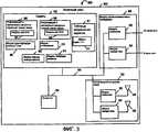
Фиг.3 предоставляет подробную иллюстрацию примерного узла 300 доступа, осуществленного в соответствии с настоящим изобретением. Примерный узел 300 доступа, изображенный на фиг.3, является подробным представлением устройства, которое может быть использовано в качестве любого из узлов 140, 140', 140'' доступа, изображенных на фиг.1. В варианте осуществления фиг.3 узел 300 доступа включает в себя процессор 304, память 310, сетевой/межсетевой интерфейс 320 и беспроводный интерфейс 330 связи, соединенные вместе с помощью шины 306. Таким образом, через шину 306 различные компоненты узла 300 доступа могут обмениваться информацией, сигналами и данными. Компоненты 304, 306, 310, 320, 330 узла 300 доступа находятся внутри корпуса.3 provides a detailed illustration of an
Сетевой/межсетевой интерфейс 320 обеспечивает механизм, с помощью которого внутренние компоненты узла 300 доступа могут посылать и принимать сигналы в/из внешних устройство и узлов сети. Сетевой/межсетевой интерфейс 320 включает в себя модуль 322 приемника и модуль 324 передатчика, используемые для соединения узла 300 с другими узлами сети, например, через медные провода или волоконно-оптические линии связи. Беспроводный интерфейс 330 связи также обеспечивает механизм, с помощью которого внутренние компоненты узла 300 доступа могут посылать и принимать сигналы в/из внешних устройств и узлов сети, например, конечных узлов. Беспроводный интерфейс 330 связи включает в себя, например, модуль 332 приемника с соответствующей приемной антенной 336 и модуль 334 передатчика с соответствующей передающей антенной 338. Интерфейс 330 используют для соединения узла 300 доступа с другими узлами сети, например, через беспроводные каналы связи.The network /
Процессор 304 под управлением различных модулей, например подпрограмм, включенных в память 310, управляет работой узла 300 доступа таким образом, чтобы выполнять различную сигнализацию и обработку. Модули, включенные в память 310, выполняются после инициализации или как вызываемые другими модулями, которые могут присутствовать в памяти 310. Модули могут обмениваться данными, информацией и сигналами при выполнении. Модули также могут совместно использовать данные и информацию при выполнении.A
В варианте осуществления фиг.3 память узла 300 доступа настоящего изобретения включает в себя модуль 314 генерации сигнала, предназначенный для генерации сигналов, модуль 350 маршрутизации пакета, ответственный за маршрутизацию сигналов и сообщений, модуль 312 преобразования, который является ответственным за отображение PID на адреса сетевого уровня, таблицу 311 разрешения адреса, включающую в себя отображения 317 PID на IP-адрес. Память 310 также включает в себя модуль 351 идентификации конечного узла, идентифицирующий конечные узлы, с которыми узел 300 доступа осуществляет связь, информацию 340 назначения ресурсов восходящей линии связи, ответственную за назначение ресурсов выходящей линии связи в конечные узлы, включая ресурсы, назначенные в конечный узел Х 341, и информацию 345 назначения ресурсов нисходящей линии связи, ответственную за назначение ресурсов нисходящей линии связи в конечные узлы, включая ресурсы, назначенные в конечный узел Х 346.In the embodiment of FIG. 3, the memory of the
Фиг.9 иллюстрирует таблицу 311' разрешения адресов, которая может быть использована в качестве таблицы 311 разрешения адресов, изображенной на фиг.3. Таблица 311' разрешения адресов включает в себя PID 902, 904, 906, 908, 910, 912 и информацию, указывающую соответствующие адреса 903, 905, 907, 909, 911 и 913 IP, соответственно. Каждый из PID является локально уникальным, например PID непосредственно соседних ячеек являются уникальными относительно друг друга. Следует заметить, что содержание PID может изменяться в зависимости от физических характеристик узла доступа и числа точек подключения физического уровня, поддерживаемых с помощью узла доступа, которому соответствует PID. В примере фиг.9 PID 902, 904 соответствуют первому узлу доступа (AN 1), который поддерживает два сектора, которые используют одну и ту же несущую. Таким образом, в случае AN 1 достаточно, чтобы PID включал в себя идентификатор ячейки и идентификатор типа сектора, чтобы однозначно идентифицировать точки подключения физического уровня в ячейке. PID 906, 908, 910 соответствуют ячейке, которая поддерживает множество несущих и множество секторов. Таким образом, PID для узла 2 доступа осуществлены как CID таким же способом, как использован в различных примерных вариантах осуществления, дополнительно обсужденных в настоящей заявке. PID 912 соответствует третьему узлу доступа, который включает в себя один сектор и использует одну несущую. Таким образом, достаточно, чтобы PID 6, который соответствует третьему узлу доступа, включал в себя только идентификатор ячейки, несмотря на дополнительную идентификацию физического уровня, например идентификатор сектора и/или канала связи. Включение такой дополнительной информации может быть желательным, когда, с точки зрения обработки, желательны совместимые форматы PID по множеству ячеек.FIG. 9 illustrates an address resolution table 311 ′, which can be used as the address resolution table 311 shown in FIG. 3. Address resolution table 311 ′ includes
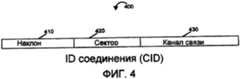
Фиг.4 иллюстрирует примерный идентификатор соединения (CID) 400, осуществленный в соответствии с этим изобретением. CID 400 включает в себя «наклон» 410, который является идентификатором ячейки, «сектор» 420, который является идентификатором сектора, и «несущую» 430, которая является идентификатором несущей частоты, также известным как идентификатор блока тонов.Figure 4 illustrates an example connection identifier (CID) 400 implemented in accordance with this invention.
В примерной системе связи, использующей технологию OFDM, на физическом уровне спектр разделяется на некоторое число тонов и повторно используется в ячейках и секторах в соседних географических областях. Для того чтобы улучшить характеристики помех, тона, используемые в каждом переходе «ячейка-сектор» во времени, и разные ячейки и секторы в соседних географических областях используют разные последовательности скачкообразных переходов, которые определяют, как должны скачкообразно изменяться тона. Последовательности скачкообразных переходов генерируются с использованием предварительно определенной функции, управляемой с помощью двух входных переменных, а именно идентификатором ячейки, например, величиной наклона и идентификатором сектора. Идентификатор сектора может быть осуществлен как идентификатор типа сектора, который указывает, какому из множества возможных типов секторов соответствует конкретный сектор. В одном варианте осуществления величина наклона является целым от 1 до 112, а величина идентификатора сектора является целым от 0 до 5. Соседние ячейки и секторы используют разные пары наклона и идентификатора сектора таким образом, чтобы генерируемые последовательности скачкообразных переходов были разными. В одном варианте осуществления все секторы в ячейке используют одинаковую величину наклона, но разные идентификаторы сектора, и соседние, например, физически смежные ячейки используют разные величины наклона.In an exemplary communication system using OFDM technology, at the physical level, the spectrum is divided into a number of tones and reused in cells and sectors in neighboring geographical areas. In order to improve the interference characteristics, the tones used in each cell-sector transition in time, and different cells and sectors in neighboring geographical areas use different sequences of jump-like transitions that determine how tones should jump-like. Jump sequences are generated using a predefined function controlled by two input variables, namely a cell identifier, for example, a slope value and a sector identifier. A sector identifier can be implemented as a sector type identifier that indicates which of the many possible sector types corresponds to a particular sector. In one embodiment, the slope value is an integer from 1 to 112, and the sector identifier value is an integer from 0 to 5. Neighboring cells and sectors use different slope and sector identifier pairs so that the generated hopping sequences are different. In one embodiment, all sectors in a cell use the same slope, but different sector identifiers, and neighboring, for example, physically adjacent cells, use different slope values.
Кроме того, примерная система связи OFDM в некоторых вариантах осуществления использует множество несущих или блоков тонов таким образом, что имеющиеся тона группируются в множество блоков тонов. Тона в блоке тонов предпочтительно являются непрерывными. В одной примерной системе скачкообразные переходы тонов в данном блоке тонов ограничены этим блоком тонов. То есть, последовательности скачкообразных переходов являются такими, что тона могут скачкообразно изменяться в блоке тонов, но не могут скачкообразно изменяться по множеству блоков тонов. Блоки тонов индексировали с помощью идентификатора несущей. В одном варианте осуществления идентификатор несущей является целым 0, 1 или 2.In addition, an exemplary OFDM communication system in some embodiments uses a plurality of carriers or blocks of tones such that available tones are grouped into a plurality of tone blocks. The tones in the tone block are preferably continuous. In one exemplary system, hopping tone transitions in a given block of tones are limited to this block of tones. That is, the sequence of jump transitions is such that tones can jump in a block of tones, but cannot jump in a plurality of blocks of tones. Tone blocks are indexed using a carrier identifier. In one embodiment, the carrier identifier is an
Когда конечный узел устанавливает соединение, чтобы получить услуги беспроводной передачи данных по сети, объектом на стороне сети является узел доступа, например базовая станция в ячейке/секторе, и соединение определяется относительно одного блока тонов. Вследствие этого в упомянутой выше примерной системе связи OFDM комбинация наклона, идентификатора сектора и идентификатора несущей может быть использована в качестве локально уникального идентификатора, который идентифицирует соединение для беспроводного терминала. Таким образом, комбинация является идентификатором соединения, основанным на одном или более идентификаторах физического уровня. В одном варианте осуществления множество беспроводных терминалов могут иметь соединения с сектором/ячейкой одной и той же базовой станции в одном и том же блоке тонов. Эти соединения обычно будут совместно использовать один и тот же идентификатор соединения, так как они соединены с одной и той же точкой подключения физического уровня, как определено с помощью комбинации ячейки, сектора и блока тонов. Комбинация идентификатора соединения и идентификатора беспроводного терминала может быть использована, чтобы идентифицировать соединение связи с конкретным беспроводным терминалом.When the end node establishes a connection to receive wireless data services over the network, the object on the network side is an access node, such as a base station in a cell / sector, and the connection is determined with respect to one tone block. As a result, in the above-mentioned exemplary OFDM communication system, the combination of tilt, sector identifier, and carrier identifier can be used as a locally unique identifier that identifies the connection for the wireless terminal. Thus, the combination is a connection identifier based on one or more physical layer identifiers. In one embodiment, a plurality of wireless terminals may have connections to a sector / cell of the same base station in the same tone block. These connections will usually share the same connection identifier, since they are connected to the same physical layer connection point, as determined using a combination of cell, sector, and tone block. The combination of a connection identifier and a wireless terminal identifier can be used to identify a communication connection with a particular wireless terminal.
Обычно идентификатор соединения является числом или комбинацией чисел, которые локально уникально идентифицируют соединение. В различных вариантах осуществления число или числа являются параметрами характеристик физического уровня. В другом варианте осуществления, например примерном варианте осуществления системы связи CDMA, идентификатор соединения может быть комбинацией сдвига псевдошумовой (PN) последовательности и другого параметра, например идентификатора несущей, если используется множество несущих.Typically, a connection identifier is a number or combination of numbers that locally uniquely identifies a connection. In various embodiments, the implementation of the number or numbers are parameters of the characteristics of the physical layer. In another embodiment, for example an example embodiment of a CDMA communication system, the connection identifier may be a combination of a PN offset and another parameter, such as a carrier identifier, if multiple carriers are used.
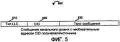
Фиг.5 иллюстрирует примерное сообщение 500 в соответствии с настоящим изобретением, которое использует идентификатор соединения фиг.4. Примерное сообщение 500 является сообщением канального уровня, которое включает в себя адрес CID /источника. Адрес CID /источника является необязательным полем в сообщениях канального уровня в соответствии с некоторыми вариантами осуществления настоящего изобретения. Сообщение 500 канального уровня включает в себя поле 510 типа управления канальным уровнем (LLC), идентифицирующим тип тела 530 сообщения, включенного в сообщение 500. CID является ID соединения в виде ID 400 соединения фиг.4. В одном варианте осуществления этого изобретения поле 520 CID идентифицирует точку физического подключения получателя, когда послано из конечного узла в узел доступа, в соответствии с изобретением, и идентифицирует физическое подключения источника, когда послано из узла доступа в конечный узел, в соответствии с изобретением.FIG. 5 illustrates an
Фиг.6 иллюстрирует примерный способ связи и соответствующую сигнализацию, выполняемую в соответствии с различными примерными вариантами осуществления изобретения. На фиг.6 конечный узел 630 взаимодействует с узлом 620 доступа через узел 610 доступа без беспроводной восходящей линии связи между конечным узлом 630 и узлом 620 доступа и без того, что конечный узел должен знать адрес IP узла 620 доступа. Сигнализация проиллюстрирована в контексте примерной системы 100, проиллюстрированной на фиг.1. Узлы 610 и 620 доступа подобным узлам 140, 140' и 140'' доступа системы 100 на фиг.1 и осуществлены в соответствии с узлом 300 доступа фиг.3. Конечный узел 630 подобен конечному узлу 144, 146, 144', 146', 144'' и 146'' системы 100 на фиг.1 и осуществлен в соответствии с конечным узлом 200 на фиг.2.6 illustrates an exemplary communication method and associated signaling performed in accordance with various exemplary embodiments of the invention. 6, the
На фиг.6 конечный узел 630 поддерживает двунаправленную линию связи с узлом 610 доступа, что означает, что он может посылать сообщения в узел 610 доступа и принимать сообщение из него. Конечный узел 630 на фиг.6, несмотря на то, что находится в диапазоне передачи узла 620 доступа, не имеет восходящей линии связи с узлом 620 доступа. Это означает, что, несмотря на то, что конечный узел 630 может принимать и обрабатывать широковещательную информацию, посланную узлом 620 доступа (например, широковещательные сообщения 640), конечный узел 630 не может посылать сообщения в узел 620 доступа через эфир, а узел 620 доступа не может принимать и обрабатывать сообщения, посланные ему конечным узлом 630 через эфирный интерфейс. В одном варианте осуществления этого изобретения это может быть вследствие того, что конечный узел 630 и узел 620 доступа не имеют достаточной временной синхронизации. Вследствие определенных ограничений, например ограниченных функциональных возможностей аппаратного обеспечения, конечный узел 630 может быть не в состоянии установить соединение восходящей линии связи с узлом 620 доступа, пока конечный узел 630 в текущий момент имеет двунаправленное соединение с узлом 610 доступа. В одном варианте осуществления восходящие линии связи, используемые узлом 610 доступа и узлом 620 доступа, находятся в разных каналах связи, например, диапазон частот восходящей линии связи, используемой узлом 610 доступа, отличается от диапазона частот восходящей линии связи, используемой узлом 620 доступа. Если конечный узел 630 может генерировать сигнал восходящей линии связи только в одном диапазоне в данный момент времени, например, вследствие того, что конечный узел 630 имеет только одну радиочастотную (RF) цепь, вследствие соображений стоимости, тогда конечный узел 630 не может одновременно поддерживать два соединения обратной связи в двух отдельных диапазонах частот. В другом варианте осуществления, в котором восходящие линии связи, используемые узлами 610 и 620 доступа, находятся в одном диапазоне частот, две восходящие линии связи не могут быть синхронизированы во времени вследствие того, что два узла доступа не синхронизированы во времени или вследствие разности задержки распространения для сигнала, чтобы достичь узлы 610 и 620 доступа из конечного узла 630. Если конечный узел 630 может генерировать только один сигнал восходящей линии связи в соответствии с одной схемой временной синхронизации в каждый данный момент времени, например, вследствие того, что конечный узел 630 имеет одну цепь цифровой обработки, ограниченную одной схемой синхронизации в каждый данный момент времени, тогда конечный узел 630 не может одновременно поддерживать два соединения восходящей линии связи, когда соединения являются недостаточно синхронизированы во времени друг с другом.6, the
Конечный узел 630 принимает широковещательный сигнал (сигналы) 640, которые передают с помощью узла 620 доступа. Сигнал (сигналы) 640 в соответствии с вариантом осуществления этого изобретения являются достаточными, чтобы определять ID соединения, подобный CID 400 по фиг.4, соответствующий конкретному физическому подключению узла 620 доступа, который передает широковещательный сигнал 640. Сигналы или сигналы 640 могут включать в себя сигнал маяка и/или пилот-сигнал, которые могут быть переданы в течение одного или более периодов времени передачи символов.The
Конечный узел 630 передает сообщение 650 в узел 610 доступа. В примерном варианте осуществления этого изобретения упомянутое сообщение 650 является тем же, что и примерное сообщение 500 фиг.5, или подобно ему. Поле CID, эквивалентное CID 520 на фиг.5, упомянутого сообщения 650 устанавливается в идентификатор соединения, который идентифицирует точку физического подключения узла 620 доступа, который передал способом широковещательной передачи сигнал 640. Таким образом, упомянутое сообщение 650 предназначено для узла 620 доступа, несмотря на то, что оно послано в узел 610 доступа. Следует заметить, что, так как конечный узел 630 в примере фиг.6 не имеет восходящей линии связи с узлом 620 доступа, он не может послать сообщение 650 непосредственно в упомянутый узел 620 доступа.
Узел 610 доступа принимает сообщение 650 и исследует поле CID, соответствующее CID 520 по фиг.5, сообщения 650 и понимает из сохраненного CID в информации идентификации канального уровня, что он не идентифицирует одну из собственных точек физического подключения. В таком случае узел 610 доступа выполняет поиск в своей памяти упомянутого CID сообщения 650, чтобы найти отображение на соответствующий идентификатор верхнего уровня для узла 620 доступа (например, адрес IP).The
Например, базовая станция, которая включает в себя множество секторов, работающих под управлением одного контроллера канального уровня, и множество несущих, используемых под управлением одного контроллера канального уровня, может иметь множество CID, соответствующих идентификатору канального уровня, соответствующему одному контроллеру канального уровня. В вариантах осуществления, в которых отдельные контроллеры канального уровня используют для каждого сектора и/или несущей разные идентификаторы канального уровня, могут быть использованы для каждого из разных секторов и/или несущих. В некоторых вариантах осуществления имеется взаимно однозначное отображение между точками физического подключения и канальными уровнями, но это является необязательным, и может быть несколько точек физического подключения, работающих под одним канальным уровнем. Таким образом, множество идентификаторов физического уровня могут соответствовать одному и тому же идентификатору несущей канального уровня, но каждый идентификатор соединения идентификатора физического уровня обычно отображается максимум на один идентификатор канального уровня.For example, a base station that includes multiple sectors operating under the control of one channel level controller and multiple carriers used under the control of one channel level controller may have multiple CIDs corresponding to a channel level identifier corresponding to one channel level controller. In embodiments where separate link layer controllers use different link layer identifiers for each sector and / or carrier, can be used for each of the different sectors and / or carriers. In some embodiments, there is a one-to-one mapping between physical connection points and channel layers, but this is optional, and there may be several physical connection points operating under one channel layer. Thus, multiple physical layer identifiers may correspond to the same link layer carrier identifier, but each link identifier of the physical layer identifier is usually mapped to a maximum of one link layer identifier.
При допущении, что найдено отображение на адрес верхнего уровня, узел 610 доступа инкапсулирует, по меньшей мере, часть сообщения 650 в сообщение 660 канального уровня, которое включает в себя адрес получателя, установленный в идентификатор узла 620 доступа, и передает упомянутое сообщение 660 в узел 620 доступа. В соответствии с этим изобретением сообщение 660 также включает в себя идентификатор конечного узла 630, причем упомянутый идентификатор в зависимости от варианта осуществления является одним из IP-адреса конечного узла 630, идентификатора доступа к сети (NAI) конечного узла 630 и временного идентификатора. Узел 620 доступа принимает упомянутое сообщение 660 и извлекает из него инкапсулированную часть сообщения 650. Узел 620 доступа анализирует поле CID извлеченной инкапсулированной части сообщения 650 и распознает, что поле CID идентифицирует одну из его собственных точек физического подключения.Assuming a mapping to a top-level address is found, the
Узел 620 доступа посылает сообщение 670, которое включает в себя, по меньшей мере, часть принятого сообщения 650, инкапсулированного в сообщении 660, с помощью узла 620 доступа. Упомянутое сообщение 670 также включает в себя идентификатор конечного узла 630, подобный идентификатору, включенному в сообщение 660. Затем узел 610 доступа принимает сообщение 670 и путем проверки включенного идентификатора конечного узла определяет, что сообщение 670 инкапсулирует сообщение 680, предназначенное для конечного узла 630. Затем узел 610 доступа посылает сообщение 680, которое включает в себя, по меньшей мере, часть сообщения 670. В соответствии с этим изобретением сообщение 680 включает в себя CID точки физического подключения узла 620 доступа, который выполняет широковещательную передачу сигнала 640.The
Конечный узел 60 принимает сообщение 680 из узла 610 доступа, но путем проверки поля CID, включенного в упомянутое сообщение 680, например сравнения его с сохраненной информацией CID, он определяет, что сообщение 680 инициировано из узла 620 доступа в ответ на сообщение 650, посланное ему ранее.End node 60 receives
Фиг.7 иллюстрирует примерную сигнализацию, выполняемую в соответствии с различными вариантами осуществления изобретения. Сигнализация проиллюстрирована в контексте примерной системы 100, проиллюстрированной на фиг.1. Конечный узел 710 является упрощенным изображением конечного узла 200 фиг.2, и он является таким же, что и конечные узлы 144, 146, 144', 146', 144'', 146'' системы 100 на фиг.1 или подобным им. Узлы 740 и 750 доступа являются подобными узлам 140, 140' и 140'' системы 100 на фиг.1 и они осуществлены с использованием узла 300 доступа фиг.3. На фиг.7 конечный узел 710 включает в себя модуль 720 генерации сообщения и модуль 730 выбора линии связи. Модуль 720 генерации сообщения фиг.7 может быть использован приложениями, выполняющимися в конечном узле 710, чтобы генерировать сообщения для их целей. Например, приложения протокола управления соединением может быть включено и активно в конечном узле 710, давая возможность конечному узлу 710 осуществлять связь с узлами доступа с целью создания, разъединения и/или модификации линий связи между конечным узлом 710 и одним или обоими из узлов 740, 750 доступа. Другим примером является приложение качества обслуживания (QoS), которое может быть включено в конечный узел 710. Приложение QoS, когда присутствует, может модифицировать характеристики QoS различных линий связи конечного узла 710. Модуль 730 выбора линии связи фиг.7 измеряет различные показатели для качества соединений, включая требования к задержке линии связи, состоянию канала линии связи, частоте появления ошибок линии связи и мощности передачи линии связи, чтобы определить, например, на основании последовательных сообщений или в определенный момент времени, какая из доступных линий связи является наиболее подходящей для передачи следующего сообщения.7 illustrates exemplary signaling performed in accordance with various embodiments of the invention. The signaling is illustrated in the context of the
Результирующая информация о качестве линии связи в различных вариантах осуществления может быть использована для того, чтобы определять, в какую из множества одновременных линий связи должно быть передано сообщение в конкретный момент времени.The resulting link quality information in various embodiments may be used to determine to which of the plurality of simultaneous links the message should be transmitted at a particular point in time.
На фиг.7 конечный узел 710 поддерживает двунаправленные линии связи с узлами 740 и 750 доступа, что означает, что он может посылать сообщения в узлы 740 и 750 доступа и принимать сообщения из них. В этом варианте осуществления модуль 720 генерации сообщения конечного узла 710 генерирует сообщение 759 с узлом 740 доступа окончательного получателя. Сообщение 759 сначала посылают в модуль 730 выбора линии связи конечного узла 710. Модуль 730 выбора линии связи выбирает линию связи среди линий связи в узлы доступа 740 и 750, через которые должно быть передано следующее сообщение. Функция определения линии связи основана на характеристиках линии связи, включающих в себя, по меньшей мере, одно из требований, предъявляемых к задержке линии связи, состоянию канала линии связи, частоте появления ошибок линии связи и мощности передачи линии связи.7, the end node 710 supports bidirectional links with access nodes 740 and 750, which means that it can send messages to and receive messages from access nodes 740 and 750. In this embodiment, the message generation module 720 of the end node 710 generates a message 759 with the final recipient access node 740. Message 759 is first sent to the communication line selection module 730 of the end node 710. The communication line selection module 730 selects the communication line from the communication lines to the access nodes 740 and 750 through which the next message is to be transmitted. The function of determining the communication line is based on the characteristics of the communication line, including at least one of the requirements for the delay of the communication line, the state of the communication channel, the frequency of occurrence of communication errors and transmission power of the communication line.
В примерном варианте осуществления этого изобретения, изображенном на фиг.7, модуль 730 выбора линии связи выбирает линию связи в узел 740 доступа и передает сообщение 760 через нее. Сообщение 760 включает в себя, по меньшей мере, некоторую часть сообщения 759 и в некоторых вариантах осуществления включает в себя дополнительные поля, используемые для передачи сообщения через линию связи между конечным узлом 710 и узлом 740 доступа. Например, в некоторых вариантах осуществления дополнительные поля являются полями кадрирования линии связи. Так как окончательным получателем сообщения 759 и 760 является узел 740 доступа, узел 740 доступа принимает сообщение 760, обрабатывает принятое сообщение и отвечает, например, передачей сообщения 765 в конечный узел 710. Сообщение 765 принимается конечным узлом 710 и доставляется в модуль генерации сообщения как сообщение 766. Модуль 720 генерации сообщения генерирует второе сообщение 769 с окончательным получателем, являющимся узлом 740 доступа. Сообщение 769 посылают в модуль 730 выбора линии связи, который выбирает линию связи, через которую должно быть передано сообщение 769. В этом варианте осуществления выбирают линию связи в узел 750 доступа, и сообщение 770 передают в узел 750 доступа. Сообщение 770 включает в себя, по меньшей мере, часть сообщения 769, а в некоторых вариантах осуществления этого изобретения включает в себя дополнительные поля, используемые для передачи сообщения через линию связи между конечным узлом 710 и 750. Например, в некоторых вариантах осуществления дополнительные поля являются полями кадрирования линии связи.In the exemplary embodiment of this invention depicted in FIG. 7, a link selector 730 selects a link to an access node 740 and transmits a message 760 through it. Message 760 includes at least some part of message 759 and, in some embodiments, includes additional fields used to transmit the message through a communication link between end node 710 and access node 740. For example, in some embodiments, additional fields are framing fields of a communication line. Since the final recipient of the message 759 and 760 is the access node 740, the access node 740 receives the message 760, processes the received message and responds, for example, by sending the message 765 to the end node 710. The message 765 is received by the end node 710 and delivered to the message generation module as a message 766. The message generation module 720 generates a second message 769 with the final recipient being the access node 740. Message 769 is sent to a communication line selection module 730, which selects a communication line through which message 769 is to be transmitted. In this embodiment, a communication line is selected in access node 750, and message 770 is transmitted in access node 750. Message 770 includes at least a portion of message 769, and in some embodiments of this invention includes additional fields used to transmit the message through a communication link between end node 710 and 750. For example, in some embodiments, additional fields are Framing fields of the communication line.
В одном варианте осуществления этого изобретения модуль 730 выбора линии связи добавляет идентификатор, например идентификатор точки физического подключения, узла 740 доступа вместе с, по меньшей мере, частью сообщения 769 в содержащее сообщение 770, так как линия связи, выбранная с помощью модуля 730 выбора линии связи для передачи сообщения 770, не соответствует окончательному получателю сообщения 770, который является узлом 740 доступа. В другом варианте осуществления этого изобретения модуль выбора линии связи добавляет идентификатор окончательного получателя сообщения 760 и 770 до того, как он передает упомянутые сообщения 760 и 770, независимо от того, какая линию связи выбрана для их передачи. В дополнительном варианте осуществления этого изобретения сообщения 759, 769 включают в себя идентификатор их окончательного получателя. Например, в примерном варианте осуществления по фиг.7 идентификатор окончательного получателя соответствует узлу 740 доступа.In one embodiment of this invention, the link selection module 730 adds an identifier, for example, an identifier of a physical connection point, of an access node 740 along with at least a portion of message 769 to the containing message 770, since the communication link selected by the line select module 730 communication for transmitting message 770 does not correspond to the final recipient of message 770, which is access node 740. In another embodiment of this invention, the link selection module adds the identifier of the final recipient of the message 760 and 770 before it transmits said messages 760 and 770, regardless of which link is selected for transmission. In a further embodiment of this invention, messages 759, 769 include the identifier of their final recipient. For example, in the exemplary embodiment of FIG. 7, the identifier of the final recipient corresponds to access node 740.
В одном примерном варианте осуществления этого изобретения сообщение 770 реализовано в соответствии с сообщением 500 на фиг.5, в котором поле 520 CID идентифицирует узел 740 доступа. Узел 750 доступа принимает сообщение 770 и обрабатывает его. Путем проверки окончательного получателя сообщения 770, например идентификатора точки физического подключения в поле 520 CID сообщения 500 фиг.5, узел 750 доступа определяет, что сообщение 770 предназначено не для него, а для другого узла, идентифицированного с помощью идентификатора окончательного получателя (например, CID в поле CID). Узел 750 доступа ищет идентификатор точки физического подключения (PID), включенный в сообщение 770 в своей таблице разрешения адресов (см. таблицу 311 разрешения адресов в узле 300 доступа фиг.3), чтобы найти адрес сети (например, адрес IP), соответствующий CID, включенному в сообщение 770.In one exemplary embodiment of this invention, message 770 is implemented in accordance with
Узел 750 доступа инкапсулирует, по меньшей мере, часть сообщения 770 в соответствующем заголовке сетевого уровня и передает сообщение 775 в узел 740 доступа. Сообщение 775 включает в себя, по меньшей мере, часть сообщения 770 и, по меньшей мере, некоторый из адресов IP узла 740 доступа. Кроме того, сообщение 775 в некоторых вариантах осуществления дополнительно может включать в себя некоторые или все из IP-адреса узла 750 доступа, PID узла 740 доступа, включенного в сообщение 770, PID узла 750 доступа, через который было принято сообщение, идентификатора конечного узла 710 и идентификаторов сеанса для инкапсуляции (также называемого туннелированием) сообщений между узлом 750 доступа и узлом 740 доступа. Узел 740 доступа принимает сообщение 775, которое распознается как сообщение, предназначенное для него, из PID получателя, включенного в сообщение 775.The access node 750 encapsulates at least a portion of the message 770 in the corresponding network layer header and transmits a message 775 to the access node 740. Message 775 includes at least a portion of message 770 and at least some of the IP addresses of access node 740. In addition, the message 775 in some embodiments may further include some or all of the IP address of the access node 750, the PID of the access node 740 included in the message 770, the PID of the access node 750 through which the message was received, the identifier of the end node 710 and session identifiers for encapsulating (also called tunneling) messages between access node 750 and access node 740. The access node 740 receives a message 775, which is recognized as a message destined for it, from the PID of the recipient included in the message 775.
В одном варианте осуществления этого изобретения узел 740 доступа отвечает передачей сообщения 780, которое включает в себя, по меньшей мере, часть сообщения 775. Узел 750 доступа принимает сообщение 780, которое включает в себя идентификатор 710 конечного узла, и посылает сообщение 785 в конечный узел 710. Сообщение 785 включает в себя, по меньшей мере, часть сообщения 780. Конечный узел 710 принимает сообщение 785 и передает сообщение 786 в модуль 720 генерации сообщения.In one embodiment of this invention, the access node 740 responds with a message 780, which includes at least a portion of the message 775. The access node 750 receives a message 780, which includes the identifier 710 of the end node, and sends a message 785 to the end node 710. Message 785 includes at least a portion of message 780. End node 710 receives message 785 and transmits message 786 to message generation module 720.
В другом варианте осуществления этого изобретения узел 740 доступа отвечает передачей в конечный узел 710 сообщения 780', включающего в себя, по меньшей мере, часть сообщения 775. Сообщение 780' передается через прямую линию связи между узлом 740 доступа и конечным узлом 710.In another embodiment of this invention, the access node 740 responds by transmitting to the end node 710 a message 780 ′ including at least a portion of the message 775. The message 780 ′ is transmitted via a direct link between the access node 740 and the end node 710.
Фиг.8 иллюстрирует примерную сигнализацию, выполняемую в соответствии с примерными вариантами осуществления изобретения, в которых конечный узел используется в качестве части процесса обнаружения соседнего узла и обновления информации маршрутизации CID. Сигнализация проиллюстрирована в контексте примерной системы, такой как система 100, проиллюстрированная на фиг.1. Конечный узел 810 является упрощенным изображением конечного узла 200 на фиг.2 и является таким же, что и конечные узлы 144, 146, 144', 146', 144'', 146'' системы 100 на фиг.1 или подобным им. Узлы 840 и 850 доступа являются такими же, что и узлы 140, 140' и 140'' системы 100 на фиг.1, и могут быть осуществлены, например, с использованием узлов доступа типа, проиллюстрированных на фиг.3. В примере фиг.8 конечный узел 810 имеет двунаправленную линию связи с узлом 840 доступа, давая возможность ему посылать сообщения в узел 840 доступа и принимать сообщение из него.FIG. 8 illustrates exemplary signaling performed in accordance with exemplary embodiments of the invention in which an end node is used as part of the process of detecting a neighboring node and updating CID routing information. The signaling is illustrated in the context of an exemplary system, such as
На фиг.8 конечный узел 810 генерирует и передает сообщение 869 в узел 840 доступа. Сообщение 860 включает в себя идентификатор, который идентифицирует узел 850 доступа как адресата упомянутого сообщения. Узел 840 доступа принимает сообщение 860 и пытается разрешить идентификатор узла 850 доступа, включенный в упомянутое сообщение, в адрес сети с помощью поиска в своей таблице разрешения адресов, например таблице 311 разрешения адресов узла 300 доступа на фиг.3. В примере по фиг.8 узел 840 доступа не достигает успеха в разрешении упомянутого идентификатора. Затем узел 840 доступа передает сообщение 865 в конечный узел 810. Сообщение 865 включает в себя указание, что маршрутизация сообщения была невозможна вследствие неуспеха разрешения.8, an
В одном варианте осуществления этого изобретения конечный узел 810 в этот момент времени устанавливает двунаправленную линию связи с узлом 850 доступа с помощью обмена множеством сообщений, изображенных как сообщение 870 с двумя стрелками на фиг.8. Однако это не обязательно, если уже существует двунаправленная линия связи с узлом 850 доступа. В другом примере, в котором использовано изобретение, конечный узел 810 уже имеет двунаправленную линию связи с узлом 850 доступа, дополнительно к линии связи с узлом 840 доступа.In one embodiment of this invention,
Используя линию связи с узлом 850 доступа, конечный узел 810 передает сообщение 875 уведомления нового соседнего узла в узел доступа 850. Сообщение 875 включает в себя, по меньшей мере, идентификатор узла 840 доступа и адрес сетевого уровня узла 840 доступа. Таким образом, узел 850 доступа получает как идентификатор, например PID узла 840 доступа, так и соответствующий адрес канального уровня, например адресом МАС, к которому узел 850 доступа может обращаться и сохранять для будущего разрешения идентификатора физического уровня в идентификатор сетевого уровня. В одном варианте осуществления этого изобретения идентификатор узла 840 доступа является идентификатором точки физического подключения, в другом варианте осуществления этого изобретения он является идентификатором канального уровня. Идентификатор сетевого уровня узла 840 доступа является известным конечному узлу 810 из соответствующих сообщений 897, передаваемых в конечный узел 810 во время или после установления линии связи с узлом 840 доступа.Using the communication link with
В альтернативном варианте осуществления этого изобретения конечный узел 810 посылает сообщение 875' вместо сообщения 875. Сообщение 875' имеет то же самое или подобное содержание сообщения сообщению 875, но оно посылается в узел 850 доступа через узел 840 доступа вместо непосредственной посылки в узел 850 доступа. Затем узел 840 доступа маршрутизирует сообщение 875' как сообщение 875'' в узел доступа 850. Следует заметить, что в отличие от сообщения 860 сообщение 875' является сообщением сетевого уровня, включающим в себя сетевой адрес узла 850 доступа в качестве его получателя. Сетевой адрес узла 850 доступа является известным конечному узлу 850 из сообщений 899 связи, передаваемых во время или после установления линии связи с узлом 850 доступа. По этой причине узел 850 доступа может маршрутизировать сообщение 875'' в узел 850 доступа с использованием сетевого адреса узла 850 доступа, например IP-адреса, без необходимости выполнять операцию разрешения CID в адрес.In an alternative embodiment of this invention,
Узел 850 доступа принимает сообщение 875 и посылает сообщение 880 создания нового соседнего узла в сетевой адрес узла 840 доступа, выбранный из сообщения 875. Сообщение 880 включает в себя идентификатор соединения для преобразований адреса сетевого уровня для узла 850 доступа. В другом варианте осуществления этого изобретения сообщение 880 включает в себя идентификаторы канального уровня для преобразований адреса сетевого уровня для узла 850 доступа. В другом варианте осуществления этого изобретения сообщение 880 включает в себя дополнительную информацию о соседних узлах, используемую для адаптации передач обслуживания конечного узла, включая адрес туннеля и идентификаторы сеанса туннеля для повторной адресации пакета между узлами 840 и 850 доступа, функциональные возможности узла 850 доступа относительно поддерживаемых качества обслуживания, нагрузки, протоколов и приложений, но не ограничено этим. Узел 840 доступа принимает сообщение 880 и сохраняет информацию, включенную в сообщение 880, в своей памяти, например, для будущего использования в операциях разрешения CID в адрес сети. Узел 840 доступа отвечает с помощью сообщения 882, подтверждающего прием упомянутой информации, включенной в сообщение 880.
В одном варианте осуществления этого изобретения узел 840 доступа включает в своем сообщении 882 некоторое из: идентификатора соединения для преобразований адреса сетевого уровня для узла доступа 850, идентификаторов канального уровня для преобразований адреса сетевого уровня для узла 850 доступа, информации о соседних узлах, используемой для адаптации передач обслуживания конечного узла, включая адрес туннеля и идентификаторы сеанса туннеля для повторной адресации пакета между узлами 840 и 850 доступа, и/или информации, указывающей функциональные возможности узла 840 доступа относительно поддерживаемых качества обслуживания, нагрузки, протоколов и приложений, но не ограничено этим. Узел 840 доступа принимает сообщение 880 и сохраняет информацию, включенную в сообщение 880, в своей памяти, например, для будущего использования в сообщениях маршрутизации. В этом конкретном варианте осуществления изобретения сообщения 883 и 884 не используют.In one embodiment of this invention, the
В другом варианте осуществления этого изобретения сообщение 882 узла 840 доступа включает в себя подтверждение приема информации, включенной в сообщение 880. В этом варианте осуществления изобретения узел 840 доступа посылает сообщение 883, включающее в себя, по меньшей мере, некоторые из: идентификатора соединения для преобразований адреса сетевого уровня для узла 850 доступа, идентификаторов канального уровня для преобразований адреса сетевого уровня узла 850 доступа, информации о соседних узлах, используемой для адаптации передач обслуживания конечного узла, включая адрес туннеля и идентификаторы сеанса туннеля для повторной адресации пакета между узлами 840 и 850 доступа, функциональных возможностей узла 840 доступа относительно поддерживаемых качества обслуживания, нагрузки, протоколов и приложений, но не ограничено этим. Узел 850 доступа принимает сообщение 883 и сохраняет информацию, включенную в сообщение 883, в своей памяти, например, для будущего использования. Узел 850 доступа отвечает с помощью сообщения 884, подтверждающего прием упомянутой информации.In another embodiment of this invention, the
После обмена информацией о соседних узлах и идентификатором для отображения адресов между узлами 840 и 850 доступа посредством сообщений 880, 882 и факультативно 883 и 884 конечный узел 810 посылает сообщение 890 в узел 840 доступа. Как сообщение 860, в одном варианте осуществления изобретения сообщение 890 также является тем же, что и сообщение 500 по фиг.5, или подобно ему. Сообщение 890 идентифицирует в качестве окончательного получателя узел 850 доступа. Узел 840 доступа принимает сообщение 890, выполняет в своей памяти поиск для отображения между идентификатором узла 850 доступа и сетевым адресом для упомянутого узла 850 и находит упомянутый сетевой адрес в своей таблице разрешения адресов, которая была ранее заполнена с помощью сообщения 880. Узел 840 доступа инкапсулирует сообщение 890 в соответствии с информацией в таблице разрешения и посылает его в узел 850 доступа в виде сообщения 891. Узел 850 доступа отвечает с помощью сообщения 892, опять с использованием информации в своей таблице разрешения адресов и сообщении 891. Узел 840 доступа посылает сообщение 893 в конечный узел 810, включающее в себя, по меньшей мере, часть сообщения 892, принятого из узла 850 доступа, заканчивая коммуникационный обмен между конечным узлом 810 и узлом 850 доступа через узел 840 доступа.After exchanging information about neighboring nodes and an identifier for mapping addresses between
В описанном выше способе посредством использования сообщений из конечного узла 810 узлы 840 и 850 доступа обеспечиваются информацией об адресе и/или PID относительно друг друга, которая затем может быть использована при маршрутизации принятых сообщений. Таким образом, когда узлы доступа добавляются к сети, конечные узлы могут служить для того, чтобы обнаруживать свое присутствие из широковещательных сигналов и уведомлять узлы доступа о новых соседних узлах. В качестве части процесса уведомления распространяется достаточная информация об адресах, чтобы облегчить маршрутизацию сообщений на основании PID сети после того, как процесс уведомления закончен.In the method described above, by using messages from the
В различных вариантах осуществления узлы, описанные в настоящей заявке, осуществлены с использованием одного или более модулей, чтобы выполнять этапы, соответствующие одному или более способам нестоящего изобретения, например этапы обработки сигналов, генерации и/или передачи сообщений. Таким образом, в некоторых вариантах осуществления различные признаки настоящего изобретения осуществлены с использованием модулей. Такие модули могут быть осуществлены с использованием программного обеспечения, аппаратного обеспечения или комбинации программного обеспечения и аппаратного обеспечения. Многие из описанных выше способов или этапов способов могут быть осуществлены с использованием инструкций, доступных для выполнения с помощью машины, таких как программное обеспечение, включенных в машиночитаемые носители, такие как устройство памяти, например RAM, гибкий диск и т.д., чтобы управлять машиной, например, универсальным компьютером с дополнительным аппаратным обеспечением или без него, чтобы осуществлять все или части описанных выше способов, например, в одном или более узлах. Таким образом, в частности, настоящее изобретение относится к машиночитаемому носителю, включающему в себя инструкции, доступные для выполнения с помощью машины, предназначенные для того, чтобы заставить машину, например процессор и связанное аппаратное обеспечение, выполнять один или более этапов описанного выше способа (способов).In various embodiments, the nodes described herein are implemented using one or more modules to perform steps corresponding to one or more methods of the invention, for example, steps for processing signals, generating and / or transmitting messages. Thus, in some embodiments, various features of the present invention are implemented using modules. Such modules may be implemented using software, hardware, or a combination of software and hardware. Many of the methods or steps described above can be implemented using machine-accessible instructions, such as software, included in computer-readable media such as a memory device, such as RAM, a floppy disk, etc., to control a machine, for example, a universal computer with or without additional hardware, to implement all or parts of the methods described above, for example, in one or more nodes. Thus, in particular, the present invention relates to a machine-readable medium including instructions available for execution by a machine, intended to cause a machine, such as a processor and related hardware, to perform one or more of the steps of the above method (methods )
Многочисленные дополнительные изменения в способах и устройстве согласно настоящему изобретению будут понятны специалистам в данной области техники ввиду приведенного выше описания изобретения. Такие изменения должны быть учтены в рамках объема изобретения. Способы и устройства согласно настоящему изобретению могут быть использованы и в различных вариантах осуществления используются с CDMA, мультиплексированием с ортогональным частотным разделением (OFDM) или различными другими типами способов связи, которые могут быть использованы, чтобы обеспечить беспроводные линии связи между узлами доступа и подвижными узлами. В некоторых вариантах осуществления узлы доступа осуществлены как базовые станции, которые устанавливают линии связи с подвижными узлами с использованием OFDM и/или CDMA. В различных вариантах осуществления подвижные узлы осуществлены как портативные переносные компьютеры, персональные цифровые помощники (PDA) или другие портативные устройства, включающие в себя схемы приемника/передатчика и логические схемы и/или подпрограммы, предназначенные для осуществления способов настоящего изобретения.Numerous additional changes to the methods and apparatus of the present invention will be apparent to those skilled in the art in view of the above description of the invention. Such changes should be considered within the scope of the invention. The methods and devices of the present invention can be used and in various embodiments used with CDMA, orthogonal frequency division multiplexing (OFDM), or various other types of communication methods that can be used to provide wireless links between access nodes and mobile nodes. In some embodiments, the access nodes are implemented as base stations that establish communication links with mobile nodes using OFDM and / or CDMA. In various embodiments, the mobile nodes are implemented as portable laptop computers, personal digital assistants (PDAs), or other portable devices including receiver / transmitter circuits and logic circuits and / or routines for implementing the methods of the present invention.
Claims (18)
Translated fromRussianгенерирование сообщения, включающего в себя идентификатор точки физического подключения, причем упомянутый идентификатор точки физического подключения является одним из упомянутых идентификаторов первой и второй точки физического подключения;
выбор на основании параметров качества линии связи одной из упомянутых первой и второй линий связи, используемых для передачи упомянутого сообщения; и
передачу упомянутого сообщения через упомянутую выбранную одну из упомянутых первой и второй линий связи.1. The method of operation of a wireless terminal having a first communication line with a first access node, said first communication line terminating in said first access node at a first physical connection point identified by an identifier of a first physical connection point, and a second communication line with a second access node wherein said second communication line terminates at said second access node at a second physical connection point identified by an identifier of a second physical connection point switching off, and the method contains:
generating a message including a physical connection point identifier, said physical connection point identifier being one of said identifiers of a first and second physical connection point;
selecting, based on the quality parameters of the communication line, one of said first and second communication lines used for transmitting said message; and
transmitting said message through said selected one of said first and second communication lines.
определение упомянутого идентификатора первой точки физического подключения из множества широковещательных сигналов, передаваемых с помощью упомянутого первого узла доступа.7. The method according to claim 3, further comprising
determining said identifier of a first physical connection point from a plurality of broadcast signals transmitted by said first access node.
определение упомянутого идентификатора второй точки физического подключения из множества широковещательных сигналов, передаваемых с помощью упомянутого второго узла доступа.8. The method according to claim 7, further comprising
determining said identifier of a second physical connection point from a plurality of broadcast signals transmitted by said second access node.
в котором передача упомянутого сообщения включает в себя передачу сигналов OFDM.9. The method of claim 8, wherein said first and second access nodes are base stations; and
wherein transmitting said message includes transmitting OFDM signals.
модуль генерации сообщения для генерации сообщения, включающего в себя идентификатор точки физического подключения, причем упомянутый идентификатор точки физического подключения является одним из упомянутых идентификаторов первой и второй точки физического подключения;
модуль выбора на основании параметров качества линии связи, линии связи для выбора одной из упомянутых первой и второй линий связи, используемых для передачи упомянутого сообщения; и
модуль передатчика для передачи упомянутого сообщения через упомянутую выбранную одну из упомянутых первой и второй линий связи.10. A wireless terminal having a first communication line with a first access node, said first communication line terminating in said first access node at a first physical connection point identified by an identifier of a first physical connection point, and a second communication line with a second access node, said second communication line terminates at said second access node at a second physical connection point identified by an identifier of a second physical connection point, the wireless terminal comprising:
a message generating module for generating a message including an identifier of a physical connection point, said identifier of a physical connection point being one of said identifiers of a first and second physical connection point;
a selection module based on the quality parameters of the communication line, the communication line for selecting one of said first and second communication lines used for transmitting said message; and
a transmitter module for transmitting said message through said selected one of said first and second communication lines.
модуль определения идентификатора точки физического подключения для определения упомянутого идентификатора первой точки физического подключения из множества широковещательных сигналов, передаваемый с помощью упомянутого первого узла доступа.16. The wireless terminal of claim 12, further comprising:
a physical connection point identifier determining module for determining said identifier of a first physical connection point from a plurality of broadcast signals transmitted by said first access node.
в котором упомянутый модуль передатчика включает в себя передатчик OFDM.18. The wireless terminal of claim 16, wherein said first and second access nodes are base stations; and
wherein said transmitter module includes an OFDM transmitter.
Applications Claiming Priority (2)
| Application Number | Priority Date | Filing Date | Title |
|---|---|---|---|
| US11/316,376US9736752B2 (en) | 2005-12-22 | 2005-12-22 | Communications methods and apparatus using physical attachment point identifiers which support dual communications links |
| US11/316,376 | 2005-12-22 |
Publications (2)
| Publication Number | Publication Date |
|---|---|
| RU2008130130A RU2008130130A (en) | 2010-01-27 |
| RU2388158C2true RU2388158C2 (en) | 2010-04-27 |
Family
ID=38180450
Family Applications (1)
| Application Number | Title | Priority Date | Filing Date |
|---|---|---|---|
| RU2008130130/09ARU2388158C2 (en) | 2005-12-22 | 2006-12-20 | Communication methods and devices using physical connection point identifiers which support dual communication lines |
Country Status (12)
| Country | Link |
|---|---|
| US (1) | US9736752B2 (en) |
| EP (1) | EP1964338B8 (en) |
| JP (2) | JP2009521866A (en) |
| KR (2) | KR101249105B1 (en) |
| CN (1) | CN101341684B (en) |
| AR (1) | AR058642A1 (en) |
| AT (1) | ATE531168T1 (en) |
| BR (1) | BRPI0620359A2 (en) |
| CA (1) | CA2630540A1 (en) |
| RU (1) | RU2388158C2 (en) |
| TW (1) | TW200738004A (en) |
| WO (1) | WO2007075954A2 (en) |
Cited By (2)
| Publication number | Priority date | Publication date | Assignee | Title |
|---|---|---|---|---|
| RU2562827C2 (en)* | 2010-04-20 | 2015-09-10 | Писител, Инк. | System and method for detection of secondary synchronisation signal (sss) at shift of carrier frequency in downlink at multiple access with orthogonal frequency division of channels |
| RU2572613C1 (en)* | 2011-11-18 | 2016-01-20 | ЭлДжи ЭЛЕКТРОНИКС ИНК. | Method of transmitting data unit in wireless local area network system and device for supporting same |
Families Citing this family (19)
| Publication number | Priority date | Publication date | Assignee | Title |
|---|---|---|---|---|
| US6360100B1 (en) | 1998-09-22 | 2002-03-19 | Qualcomm Incorporated | Method for robust handoff in wireless communication system |
| US7668541B2 (en) | 2003-01-31 | 2010-02-23 | Qualcomm Incorporated | Enhanced techniques for using core based nodes for state transfer |
| US8982778B2 (en) | 2005-09-19 | 2015-03-17 | Qualcomm Incorporated | Packet routing in a wireless communications environment |
| US9078084B2 (en) | 2005-12-22 | 2015-07-07 | Qualcomm Incorporated | Method and apparatus for end node assisted neighbor discovery |
| US9066344B2 (en) | 2005-09-19 | 2015-06-23 | Qualcomm Incorporated | State synchronization of access routers |
| US8983468B2 (en) | 2005-12-22 | 2015-03-17 | Qualcomm Incorporated | Communications methods and apparatus using physical attachment point identifiers |
| US8509799B2 (en) | 2005-09-19 | 2013-08-13 | Qualcomm Incorporated | Provision of QoS treatment based upon multiple requests |
| US9083355B2 (en) | 2006-02-24 | 2015-07-14 | Qualcomm Incorporated | Method and apparatus for end node assisted neighbor discovery |
| US9155008B2 (en) | 2007-03-26 | 2015-10-06 | Qualcomm Incorporated | Apparatus and method of performing a handoff in a communication network |
| US8830818B2 (en) | 2007-06-07 | 2014-09-09 | Qualcomm Incorporated | Forward handover under radio link failure |
| US9094173B2 (en) | 2007-06-25 | 2015-07-28 | Qualcomm Incorporated | Recovery from handoff error due to false detection of handoff completion signal at access terminal |
| US9477940B2 (en)* | 2007-07-23 | 2016-10-25 | International Business Machines Corporation | Relationship-centric portals for communication sessions |
| US8848656B2 (en)* | 2007-11-16 | 2014-09-30 | Qualcomm Incorporated | Utilizing broadcast signals to convey restricted association information |
| US9603062B2 (en) | 2007-11-16 | 2017-03-21 | Qualcomm Incorporated | Classifying access points using pilot identifiers |
| US8902867B2 (en) | 2007-11-16 | 2014-12-02 | Qualcomm Incorporated | Favoring access points in wireless communications |
| US8281023B2 (en)* | 2008-11-14 | 2012-10-02 | Qualcomm Incorporated | Systems and methods for data authorization in distributed storage networks |
| US8615241B2 (en) | 2010-04-09 | 2013-12-24 | Qualcomm Incorporated | Methods and apparatus for facilitating robust forward handover in long term evolution (LTE) communication systems |
| EP4213537A1 (en)* | 2010-09-28 | 2023-07-19 | BlackBerry Limited | Method in a core network, mobility management entity and non-transitory storage medium |
| JP5891623B2 (en)* | 2011-07-07 | 2016-03-23 | ソニー株式会社 | COMMUNICATION CONTROL DEVICE, COMMUNICATION CONTROL METHOD, AND PROGRAM |
Citations (2)
| Publication number | Priority date | Publication date | Assignee | Title |
|---|---|---|---|---|
| RU2000100350A (en)* | 1997-06-06 | 2001-11-27 | Сэлбу Рисерч Энд Дивелопмент (Пропрайэтэри) Лимитед | MULTI-STATION NETWORK METHOD |
| US6519457B1 (en)* | 1997-04-09 | 2003-02-11 | Nortel Networks Limited | Methods and systems for standardizing interbase station communications |
Family Cites Families (392)
| Publication number | Priority date | Publication date | Assignee | Title |
|---|---|---|---|---|
| US4833701A (en) | 1988-01-27 | 1989-05-23 | Motorola, Inc. | Trunked communication system with nationwide roaming capability |
| JPH0284807A (en) | 1988-09-20 | 1990-03-26 | Hitachi Ltd | digital signal processing equipment |
| DE3888699T2 (en) | 1988-10-03 | 1994-07-21 | Alcatel Nv | NEWS MEDIATION ELEMENT. |
| US5128938A (en) | 1989-03-03 | 1992-07-07 | Motorola, Inc. | Energy saving protocol for a communication system |
| JPH03268697A (en) | 1990-03-19 | 1991-11-29 | Fujitsu Ltd | Mobile radio communication system |
| US5208837A (en) | 1990-08-31 | 1993-05-04 | Allied-Signal Inc. | Stationary interference cancellor |
| US5200952A (en)* | 1991-03-28 | 1993-04-06 | Sprint International Communications Corp. | Adaptive VCP control in integrated services networks |
| US5229992A (en) | 1991-03-28 | 1993-07-20 | Sprint International Communications Corp. | Fixed interval composite framing in integrated services networks |
| US5247516A (en) | 1991-03-28 | 1993-09-21 | Sprint International Communications Corp. | Configurable composite data frame |
| US5251209A (en) | 1991-03-28 | 1993-10-05 | Sprint International Communications Corp. | Prioritizing attributes in integrated services networks |
| US5268933A (en) | 1991-09-27 | 1993-12-07 | Motorola, Inc. | Data packet alignment in a communication system |
| FI100043B (en) | 1992-01-23 | 1997-08-29 | Nokia Telecommunications Oy | Planning method and system for cellular radio network |
| US5267261A (en) | 1992-03-05 | 1993-11-30 | Qualcomm Incorporated | Mobile station assisted soft handoff in a CDMA cellular communications system |
| FI98672C (en) | 1992-04-24 | 1997-07-25 | Nokia Telecommunications Oy | radio system |
| US5870427A (en)* | 1993-04-14 | 1999-02-09 | Qualcomm Incorporated | Method for multi-mode handoff using preliminary time alignment of a mobile station operating in analog mode |
| US5694548A (en) | 1993-06-29 | 1997-12-02 | International Business Machines Corporation | System and method for providing multimedia quality of service sessions in a communications network |
| US5388102A (en)* | 1993-07-01 | 1995-02-07 | At&T Corp. | Arrangement for synchronizing a plurality of base stations |
| US5471670A (en) | 1993-07-02 | 1995-11-28 | Motorola, Inc. | Method for determining communciation resource handoffs |
| US6157668A (en) | 1993-10-28 | 2000-12-05 | Qualcomm Inc. | Method and apparatus for reducing the average transmit power of a base station |
| US5491835A (en)* | 1994-02-18 | 1996-02-13 | Motorola, Inc. | Method for maintaining audience continuity of a communication group call |
| KR970000668B1 (en) | 1994-02-21 | 1997-01-16 | 재단법인 한국전자통신연구소 | Traffic output suppression apparatus and method for preventing congestion in asynchronous delivery mode (ATM) network |
| US5548812A (en)* | 1994-07-21 | 1996-08-20 | Qualcomm Incorporated | Method and apparatus for balancing the forward link handoff boundary to the reverse link handoff boundary in a cellular communication system |
| WO1996005709A1 (en)* | 1994-08-09 | 1996-02-22 | Pacific Communication Sciences, Inc. | Method and apparatus for efficient handoffs by mobile communication entities |
| US5490139A (en)* | 1994-09-28 | 1996-02-06 | International Business Machines Corporation | Mobility enabling access point architecture for wireless attachment to source routing networks |
| US5509027A (en)* | 1994-12-05 | 1996-04-16 | Motorola, Inc. | Synchronization method in a frequency hopping local area network having dedicated control channels |
| US5572528A (en) | 1995-03-20 | 1996-11-05 | Novell, Inc. | Mobile networking method and apparatus |
| JP3047767B2 (en)* | 1995-03-20 | 2000-06-05 | 株式会社日立製作所 | Wireless LAN system |
| US5586121A (en) | 1995-04-21 | 1996-12-17 | Hybrid Networks, Inc. | Asymmetric hybrid access system and method |
| GB9508696D0 (en) | 1995-04-28 | 1995-06-14 | At & T Corp | Method for connecting roaming stations in a source routed bridged local area network |
| US5794137A (en) | 1995-07-17 | 1998-08-11 | Ericsson Inc. | Method for increasing stand-by time in portable radiotelephones |
| US5737328A (en)* | 1995-10-04 | 1998-04-07 | Aironet Wireless Communications, Inc. | Network communication system with information rerouting capabilities |
| US6442616B1 (en) | 1997-01-16 | 2002-08-27 | Kabushiki Kaisha Toshiba | Method and apparatus for communication control of mobil computers in communication network systems using private IP addresses |
| US5907542A (en) | 1996-04-15 | 1999-05-25 | Ascom Tech Ag | Dynamic assignment of signalling virtual channels for wireless ATM systems |
| US6055427A (en) | 1996-07-18 | 2000-04-25 | Nokia Telecommunications Oy | Hard handoff and a radio system |
| US5854785A (en) | 1996-12-19 | 1998-12-29 | Motorola, Inc. | System method and wireless communication device for soft handoff |
| US5978366A (en) | 1996-12-20 | 1999-11-02 | Ericsson Inc. | Methods and systems for reduced power operation of cellular mobile terminals |
| US5974036A (en) | 1996-12-24 | 1999-10-26 | Nec Usa, Inc. | Handoff-control technique for wireless ATM |
| US6034950A (en)* | 1996-12-27 | 2000-03-07 | Motorola Inc. | System packet-based centralized base station controller |
| US6018521A (en)* | 1996-12-27 | 2000-01-25 | Motorola, Inc. | Network interface subsystem for use in an ATM communications system |
| US6049543A (en) | 1996-12-27 | 2000-04-11 | Motorola, Inc. | Transcoder for use in an ATM-based communications system |
| US6496704B2 (en) | 1997-01-07 | 2002-12-17 | Verizon Laboratories Inc. | Systems and methods for internetworking data networks having mobility management functions |
| US6151502A (en) | 1997-01-29 | 2000-11-21 | Qualcomm Incorporated | Method and apparatus for performing soft hand-off in a wireless communication system |
| FI980351L (en) | 1997-02-19 | 1998-08-20 | Nokia Telecommunications Oy | Cellular radio access network and location updating in a wireless communication system |
| US6144671A (en) | 1997-03-04 | 2000-11-07 | Nortel Networks Corporation | Call redirection methods in a packet based communications network |
| US6137787A (en) | 1997-04-03 | 2000-10-24 | Chawla; Kapil K. | Method and apparatus for resource assignment in a wireless communication system |
| FI109503B (en) | 1997-04-15 | 2002-08-15 | Nokia Corp | Prevention of packet loss during handover in a packet-based telecommunications network and handover procedure |
| US6073021A (en) | 1997-05-30 | 2000-06-06 | Lucent Technologies, Inc. | Robust CDMA soft handoff |
| ID24678A (en) | 1997-06-06 | 2000-07-27 | Salbu Res & Dev Pty Ltd | OPERATION METHOD OF A MULTI STATION NETWORK |
| EP0891114A1 (en) | 1997-07-12 | 1999-01-13 | Telefonaktiebolaget Lm Ericsson | Method and system for performing an optimised hand over |
| US6055428A (en) | 1997-07-21 | 2000-04-25 | Qualcomm Incorporated | Method and apparatus for performing soft hand-off in a wireless communication system |
| US6937566B1 (en) | 1997-07-25 | 2005-08-30 | Telefonaktiebolaget Lm Ericsson (Publ) | Dynamic quality of service reservation in a mobile communications network |
| US6148201A (en) | 1997-08-06 | 2000-11-14 | Nortel Networks Corporation | Scalable wireless network architecture based on subscriber distribution |
| US6285665B1 (en) | 1997-10-14 | 2001-09-04 | Lucent Technologies Inc. | Method for establishment of the power level for uplink data transmission in a multiple access system for communications networks |
| US6400722B1 (en) | 1997-10-14 | 2002-06-04 | Lucent Technologies Inc. | Optimum routing system |
| US6157833A (en) | 1997-11-14 | 2000-12-05 | Motorola, Inc. | Method for reducing status reporting in a wireless communication systems |
| JP3082730B2 (en) | 1997-11-18 | 2000-08-28 | 日本電気株式会社 | Mobile incoming call control method and mobile incoming call control system |
| US7130291B1 (en) | 1997-11-26 | 2006-10-31 | Lg Electronics, Inc. | Data control system in CDMA mobile communication system providing mobile data and voice service |
| US5999522A (en) | 1997-11-26 | 1999-12-07 | Motorola, Inc. | Method and apparatus for determining hand-off candidates in a communication system |
| DE69822283T2 (en) | 1997-12-24 | 2004-07-29 | Nortel Networks Ltd., St. Laurent | Distributed persistent storage for user-provider systems with sometimes broken connections |
| US6101394A (en) | 1997-12-24 | 2000-08-08 | Nortel Networks Corporation | CDMA multiple carrier paging channel optimization |
| US6084969A (en) | 1997-12-31 | 2000-07-04 | V-One Corporation | Key encryption system and method, pager unit, and pager proxy for a two-way alphanumeric pager network |
| US6535493B1 (en)* | 1998-01-15 | 2003-03-18 | Symbol Technologies, Inc. | Mobile internet communication protocol |
| KR100414932B1 (en) | 1998-01-24 | 2004-04-03 | 삼성전자주식회사 | Method for communication data in cdma system |
| JP3641128B2 (en)* | 1998-02-20 | 2005-04-20 | 株式会社東芝 | MOBILE COMPUTER DEVICE, MOBILE COMPUTER MANAGEMENT DEVICE, MOBILE COMPUTER MANAGEMENT METHOD, AND COMMUNICATION CONTROL METHOD |
| US6201971B1 (en)* | 1998-03-26 | 2001-03-13 | Nokia Mobile Phones Ltd. | Apparatus, and associated method for controlling service degradation performance of communications in a radio communication system |
| FI108772B (en) | 1998-03-31 | 2002-03-15 | Nokia Corp | Procedure for controlling the connections to a mobile station |
| US6493725B1 (en) | 1998-05-18 | 2002-12-10 | Sharp Kabushiki Kaisha | Database managing system |
| JPH11341541A (en) | 1998-05-22 | 1999-12-10 | Hitachi Ltd | Packet transfer method for mobile communication system, terminal base station used for mobile communication system, and mobile communication system |
| JP3522534B2 (en) | 1998-05-25 | 2004-04-26 | 京セラミタ株式会社 | Intermediate transfer device for image forming apparatus |
| KR100291476B1 (en)* | 1998-05-25 | 2001-07-12 | 윤종용 | A method and a system for controlling a pilot measurement request order in cellular system |
| US6163692A (en) | 1998-05-28 | 2000-12-19 | Lucent Technologies, Inc. | Telecommunication network with mobile voice conferencing system and method |
| JP3517214B2 (en)* | 1998-06-13 | 2004-04-12 | サムスン エレクトロニクス カンパニー リミテッド | State synchronization method between base station and mobile station in code division multiple access mobile communication system |
| KR100277058B1 (en) | 1998-06-15 | 2001-01-15 | 윤종용 | A method for deciding the starting time of inter-frequency hard handoff and a method for initiating of hard handoff in mobile telecommunication system |
| EP1088463B1 (en) | 1998-06-19 | 2010-04-21 | Telefonaktiebolaget LM Ericsson (publ) | Method and apparatus for dynamically adapting a connection state in a mobile communications system |
| US6594238B1 (en)* | 1998-06-19 | 2003-07-15 | Telefonaktiebolaget Lm Ericsson (Publ) | Method and apparatus for dynamically adapting a connection state in a mobile communications system |
| US6195705B1 (en)* | 1998-06-30 | 2001-02-27 | Cisco Technology, Inc. | Mobile IP mobility agent standby protocol |
| US6317754B1 (en) | 1998-07-03 | 2001-11-13 | Mitsubishi Electric Research Laboratories, Inc | System for user control of version /Synchronization in mobile computing |
| US6345043B1 (en)* | 1998-07-06 | 2002-02-05 | National Datacomm Corporation | Access scheme for a wireless LAN station to connect an access point |
| US5978365A (en) | 1998-07-07 | 1999-11-02 | Orbital Sciences Corporation | Communications system handoff operation combining turbo coding and soft handoff techniques |
| US6640248B1 (en) | 1998-07-10 | 2003-10-28 | Malibu Networks, Inc. | Application-aware, quality of service (QoS) sensitive, media access control (MAC) layer |
| US6516352B1 (en)* | 1998-08-17 | 2003-02-04 | Intel Corporation | Network interface system and method for dynamically switching between different physical layer devices |
| US6157978A (en) | 1998-09-16 | 2000-12-05 | Neomagic Corp. | Multimedia round-robin arbitration with phantom slots for super-priority real-time agent |
| US6360100B1 (en) | 1998-09-22 | 2002-03-19 | Qualcomm Incorporated | Method for robust handoff in wireless communication system |
| US6317596B1 (en) | 1998-10-20 | 2001-11-13 | Denso Corporation | Error detecting and reporting system in a wireless communication network |
| US6446127B1 (en) | 1998-10-30 | 2002-09-03 | 3Com Corporation | System and method for providing user mobility services on a telephony network |
| US6160804A (en) | 1998-11-13 | 2000-12-12 | Lucent Technologies Inc. | Mobility management for a multimedia mobile network |
| US6161008A (en) | 1998-11-23 | 2000-12-12 | Nortel Networks Limited | Personal mobility and communication termination for users operating in a plurality of heterogeneous networks |
| US6763007B1 (en) | 1998-12-11 | 2004-07-13 | Lucent Technologies Inc. | Two phase local mobility scheme for wireless access to packet based networks |
| EP1011274A1 (en)* | 1998-12-16 | 2000-06-21 | TELEFONAKTIEBOLAGET L M ERICSSON (publ) | Method and service providing means for providing services in a telecommunication network |
| WO2000038348A1 (en) | 1998-12-18 | 2000-06-29 | Nokia Networks Oy | A method for traffic load control in a telecommunication network |
| JP2002538637A (en) | 1999-01-04 | 2002-11-12 | テレフォンアクチーボラゲット エル エム エリクソン(パブル) | Bearer service negotiations |
| FI108601B (en) | 1999-01-05 | 2002-02-15 | Nokia Corp | Dissemination of QoS mapping information in a packet radio network |
| US6272129B1 (en) | 1999-01-19 | 2001-08-07 | 3Com Corporation | Dynamic allocation of wireless mobile nodes over an internet protocol (IP) network |
| US6370380B1 (en) | 1999-02-17 | 2002-04-09 | Telefonaktiebolaget Lm Ericsson (Publ) | Method for secure handover |
| US6473418B1 (en) | 1999-03-11 | 2002-10-29 | Flarion Technologies, Inc. | Orthogonal frequency division multiplexing based spread spectrum multiple access |
| US6516189B1 (en)* | 1999-03-17 | 2003-02-04 | Telephia, Inc. | System and method for gathering data from wireless communications networks |
| FR2792155B1 (en)* | 1999-04-09 | 2001-06-29 | Nortel Matra Cellular | METHOD FOR PROVIDING SERVICES TO MOBILE RADIO COMMUNICATION STATIONS, NETWORK EQUIPMENT AND MOBILE STATIONS FOR IMPLEMENTING SAME |
| EP1175795A1 (en) | 1999-04-30 | 2002-01-30 | Nokia Corporation | Sgsn semi anchoring during the inter sgsn srnc relocation procedure |
| DE19922288A1 (en) | 1999-05-14 | 2000-11-23 | Siemens Ag | Arrangement for mobile communication |
| US6466964B1 (en) | 1999-06-15 | 2002-10-15 | Cisco Technology, Inc. | Methods and apparatus for providing mobility of a node that does not support mobility |
| GB9918636D0 (en) | 1999-08-06 | 1999-10-13 | Nokia Telecommunications Oy | Inter-system handover |
| US6728365B1 (en) | 1999-09-13 | 2004-04-27 | Nortel Networks Limited | Method and system for providing quality-of-service on packet-based wireless connections |
| WO2001028160A2 (en) | 1999-10-14 | 2001-04-19 | Nortel Networks Limited | Establishing a communications session having a quality of service in a communications system |
| US6366561B1 (en) | 1999-11-03 | 2002-04-02 | Qualcomm Inc. | Method and apparatus for providing mobility within a network |
| US6300887B1 (en) | 1999-11-09 | 2001-10-09 | Nokia Networks Oy | Efficient handoff procedure for header compression |
| US6587680B1 (en) | 1999-11-23 | 2003-07-01 | Nokia Corporation | Transfer of security association during a mobile terminal handover |
| US6445922B1 (en) | 1999-12-15 | 2002-09-03 | Lucent Technologies Inc. | Method and system for support of overlapping IP addresses between an interworking function and a mobile IP foreign agent |
| US6611695B1 (en) | 1999-12-20 | 2003-08-26 | Nortel Networks Limited | Method and apparatus for assigning frequency channels to a beam in a multi-beam cellular communications system |
| US6654363B1 (en) | 1999-12-28 | 2003-11-25 | Nortel Networks Limited | IP QOS adaptation and management system and method |
| US6430414B1 (en) | 1999-12-29 | 2002-08-06 | Qualcomm Incorporated | Soft handoff algorithm and wireless communication system for third generation CDMA systems |
| EP1113694A1 (en)* | 1999-12-31 | 2001-07-04 | Mitsubishi Electric Information Technology Centre Europe B.V. | Method of reducing base station overloading |
| US6438117B1 (en) | 2000-01-07 | 2002-08-20 | Qualcomm Incorporated | Base station synchronization for handover in a hybrid GSM/CDMA network |
| DE10001608A1 (en) | 2000-01-17 | 2001-07-19 | Bosch Gmbh Robert | Operating method for mobile radio network, involves stopping packet forwarding to primary base station, based on the identifier, when the connection between mobile and secondary base stations is switched |
| US20040015607A1 (en)* | 2000-01-28 | 2004-01-22 | Bender Paul E. | System and method for using an IP address as a wireless unit identifier |
| JP3712337B2 (en) | 2000-01-28 | 2005-11-02 | 三菱電機株式会社 | Communication network system and failure notification method in communication network system |
| JP4060021B2 (en) | 2000-02-21 | 2008-03-12 | 富士通株式会社 | Mobile communication service providing system and mobile communication service providing method |
| US6707813B1 (en) | 2000-02-21 | 2004-03-16 | Telefonaktiebolaget L M Ericsson (Publ) | Method of call control to minimize delays in launching multimedia or voice calls in a packet-switched radio telecommunications network |
| CA2330988A1 (en) | 2000-02-22 | 2001-08-22 | Lucent Technologies Inc. | System and method for enhancing inter-site forward traffic capacity for a soft hand-off |
| JP2001245355A (en) | 2000-03-01 | 2001-09-07 | Mitsubishi Electric Corp | Packet transmission system in mobile communication |
| US6947401B2 (en) | 2000-03-08 | 2005-09-20 | Telefonaktiebolaget Lm Ericsson (Publ) | Hierarchical mobility management for wireless networks |
| CA2302461A1 (en)* | 2000-03-27 | 2001-09-27 | William Martin Snelgrove | Wireless local loop |
| US6768908B1 (en) | 2000-04-07 | 2004-07-27 | Motorola, Inc. | Method and apparatus for soft handoff communications in a communication system operating according to IS-95B and IS-95C standards |
| US6535739B1 (en) | 2000-04-07 | 2003-03-18 | Qualcomm Incorporated | Method of handoff within a telecommunications system containing digital base stations with different spectral capabilities |
| US6992994B2 (en)* | 2000-04-17 | 2006-01-31 | Telcordia Technologies, Inc. | Methods and systems for a generalized mobility solution using a dynamic tunneling agent |
| JP4294829B2 (en) | 2000-04-26 | 2009-07-15 | ウォーターフロント・テクノロジーズ エルエルシー | Mobile network system |
| AU2000245676A1 (en)* | 2000-05-22 | 2001-12-03 | Nokia Corporation | System and method for providing a connection in a communication network |
| JP4201466B2 (en) | 2000-07-26 | 2008-12-24 | 富士通株式会社 | VPN system and VPN setting method in mobile IP network |
| KR100369807B1 (en)* | 2000-08-05 | 2003-01-30 | 삼성전자 주식회사 | Packets transmission method for mobile internet |
| US6990088B2 (en)* | 2000-08-18 | 2006-01-24 | Telefonaktiebolaget L M Ericsson (Publ) | Handoff in radio telecommunications networks |
| KR100342501B1 (en) | 2000-08-19 | 2002-06-28 | 윤종용 | Method and apparatus for managing dormant state in a wireless packet data system |
| US6487184B1 (en) | 2000-08-25 | 2002-11-26 | Motorola, Inc. | Method and apparatus for supporting radio acknowledgement information for a uni-directional user data channel |
| US7315554B2 (en)* | 2000-08-31 | 2008-01-01 | Verizon Communications Inc. | Simple peering in a transport network employing novel edge devices |
| JP2002111732A (en) | 2000-10-02 | 2002-04-12 | Nippon Telegr & Teleph Corp <Ntt> | VPN system and VPN setting method |
| GB2367980B (en)* | 2000-10-09 | 2004-03-17 | Ericsson Telefon Ab L M | Mobile hosts |
| WO2002032052A2 (en) | 2000-10-10 | 2002-04-18 | The Regents Of The University Of California | Method for maintaining reservation state in a network router |
| US7870196B2 (en) | 2000-11-08 | 2011-01-11 | Nokia Corporation | System and methods for using an application layer control protocol transporting spatial location information pertaining to devices connected to wired and wireless internet protocol networks |
| JP3961763B2 (en) | 2000-11-22 | 2007-08-22 | 株式会社エヌ・ティ・ティ・ドコモ | Base station of multi-network connection type communication system and connection method thereof |
| US6714777B1 (en) | 2000-11-22 | 2004-03-30 | Winphoria Networks, Inc. | System and method of managing supplementary features in the presence of a proxy switch in a mobile communications network |
| US7016336B2 (en)* | 2000-11-22 | 2006-03-21 | Telefonaktiebolaget L M Ericsson (Publ) | Administrative domains for personal area networks |
| JP3639208B2 (en) | 2000-11-28 | 2005-04-20 | 株式会社東芝 | Mobile communication system, mobile terminal device, AAAH server device, authentication charging service providing method, authentication charging service enjoying method, mobile terminal device information providing method, and partner terminal confirmation method |
| US6708031B2 (en)* | 2000-12-05 | 2004-03-16 | Nokia Corporation | Session or handoff methods in wireless networks |
| US7079511B2 (en) | 2000-12-06 | 2006-07-18 | Qualcomm, Incorporated | Method and apparatus for handoff of a wireless packet data services connection |
| US6760344B2 (en) | 2000-12-19 | 2004-07-06 | Nortel Networks Limited | Method and apparatus for providing differentiated quality of service in a GPRS network |
| WO2002052825A1 (en)* | 2000-12-22 | 2002-07-04 | Nokia Corporation | Method and system for establishing a multimedia connection by negotiating capability in an outband control channel |
| JP3552038B2 (en) | 2000-12-25 | 2004-08-11 | 日本電気株式会社 | Transmission power control method, reception method, mobile communication system and mobile terminal |
| KR100551867B1 (en) | 2000-12-28 | 2006-02-13 | 엘지전자 주식회사 | External Agent Handoff Notification and Control Method of Mobile Node |
| US6914883B2 (en) | 2000-12-28 | 2005-07-05 | Alcatel | QoS monitoring system and method for a high-speed DiffServ-capable network element |
| US7290063B2 (en) | 2001-01-10 | 2007-10-30 | Nokia Corporation | Relocating context information in header compression |
| WO2002056551A1 (en) | 2001-01-16 | 2002-07-18 | Xanten Ab | Routing of data packets below the ip-level in a packet-switched communication network |
| US6950650B2 (en) | 2001-02-12 | 2005-09-27 | Siemens Ag | System and method for call forwarding synchronization in a communication system |
| JP3496646B2 (en) | 2001-02-22 | 2004-02-16 | 日本電気株式会社 | Base station designating system and base station designating method in CDMA system |
| JP2002281539A (en) | 2001-03-14 | 2002-09-27 | Ntt Communications Kk | Terminal distribution information management system, method and apparatus |
| DE60227848D1 (en) | 2001-03-14 | 2008-09-04 | Nec Corp | Management system for mobile terminals, mobile terminal and program |
| GB2373595B (en) | 2001-03-15 | 2005-09-07 | Italtel Spa | A system of distributed microprocessor interfaces toward macro-cell based designs implemented as ASIC or FPGA bread boarding and relative common bus protocol |
| US20020136226A1 (en) | 2001-03-26 | 2002-09-26 | Bluesocket, Inc. | Methods and systems for enabling seamless roaming of mobile devices among wireless networks |
| KR100896228B1 (en) | 2001-03-28 | 2009-05-08 | 콸콤 인코포레이티드 | Power Control for Point-to-Multipoint Services Provided in Communication Systems |
| US6771962B2 (en) | 2001-03-30 | 2004-08-03 | Nokia Corporation | Apparatus, and an associated method, by which to provide temporary identifiers to a mobile node involved in a communication handover |
| EP1250022A1 (en)* | 2001-04-09 | 2002-10-16 | Lucent Technologies Inc. | Providing quality of service in a telecommunications system such as a UMTS or other third generation system |
| US7068654B1 (en) | 2001-04-18 | 2006-06-27 | 3Com Corporation | System and method for providing masquerading using a multiprotocol label switching |
| WO2002089514A1 (en)* | 2001-04-26 | 2002-11-07 | Nokia Corporation | Method and network element for controlling handover |
| US6957066B1 (en) | 2001-05-16 | 2005-10-18 | Cisco Technology, Inc. | Method and apparatus for registering a mobile device |
| JP4433126B2 (en)* | 2001-05-17 | 2010-03-17 | 日本電気株式会社 | Base station selection method, mobile station and base station |
| US20030018774A1 (en)* | 2001-06-13 | 2003-01-23 | Nokia Corporation | System and method for load balancing in ad hoc networks |
| US6954442B2 (en) | 2001-06-14 | 2005-10-11 | Flarion Technologies, Inc. | Methods and apparatus for using a paging and location server to support session signaling |
| US6970445B2 (en) | 2001-06-14 | 2005-11-29 | Flarion Technologies, Inc. | Methods and apparatus for supporting session signaling and mobility management in a communications system |
| US6854013B2 (en) | 2001-06-25 | 2005-02-08 | Nortel Networks Limited | Method and apparatus for optimizing network service |
| US7027400B2 (en) | 2001-06-26 | 2006-04-11 | Flarion Technologies, Inc. | Messages and control methods for controlling resource allocation and flow admission control in a mobile communications system |
| AU2002351589A1 (en)* | 2001-06-27 | 2003-03-03 | Brilliant Optical Networks | Distributed information management schemes for dynamic allocation and de-allocation of bandwidth |
| DE10133473C1 (en) | 2001-07-10 | 2003-02-20 | Siemens Ag | Process for the optimized use of SCTP (Stream Control Transmission Protocol) in MPLS (Multi Protocol Label Switching) networks |
| US7123599B2 (en) | 2001-07-13 | 2006-10-17 | Hitachi, Ltd. | Mobile communication system |
| US7339908B2 (en)* | 2001-07-31 | 2008-03-04 | Arraycomm, Llc. | System and related methods to facilitate delivery of enhanced data services in a mobile wireless communications environment |
| US8042619B2 (en)* | 2001-08-01 | 2011-10-25 | Firetrace Usa, Llc | Methods and apparatus for extinguishing fires |
| US20030027572A1 (en)* | 2001-08-03 | 2003-02-06 | Telefonaktiebolaget L M Ericsson (Publ) | Method and system for primary paging location of mobile terminal |
| KR100407344B1 (en)* | 2001-08-08 | 2003-11-28 | 삼성전자주식회사 | Method for fast access handoff in a mobile communication system |
| US7606155B2 (en) | 2001-08-09 | 2009-10-20 | Panasonic Corporation | Transmission apparatus and transmission method |
| JP3789786B2 (en) | 2001-08-15 | 2006-06-28 | 日本電信電話株式会社 | Mobile communication system, home agent, communication partner terminal, mobile terminal, mobile communication method, program, and recording medium |
| US7349380B2 (en) | 2001-08-15 | 2008-03-25 | Meshnetworks, Inc. | System and method for providing an addressing and proxy scheme for facilitating mobility of wireless nodes between wired access points on a core network of a communications network |
| KR100383587B1 (en) | 2001-08-16 | 2003-05-14 | 삼성전자주식회사 | Mobile internet protocol system and it's routing optimization method |
| US20030036392A1 (en)* | 2001-08-17 | 2003-02-20 | Satoru Yukie | Wireless network gateway |
| JP4036627B2 (en) | 2001-09-27 | 2008-01-23 | 株式会社エヌ・ティ・ティ・ドコモ | Mobile communication system, mobile communication method, base station, and mobile station |
| KR100450961B1 (en) | 2001-09-28 | 2004-10-02 | 삼성전자주식회사 | Apparatus and method for coincidence of subscriber status between public land mobile network and private network |
| KR100429533B1 (en) | 2001-10-26 | 2004-05-03 | 삼성전자주식회사 | Hand-off method in mobile communication system having flat structure |
| US7684798B2 (en) | 2001-11-09 | 2010-03-23 | Nokia Corporation | Method of pre-authorizing handovers among access routers in communication networks |
| JP4012394B2 (en) | 2001-11-13 | 2007-11-21 | 株式会社エヌ・ティ・ティ・ドコモ | Mobile communication terminal, broadcast information storage method, cell transition method, and mobile communication system |
| US20030104814A1 (en) | 2001-11-30 | 2003-06-05 | Docomo Communications Laboratories Usa | Low latency mobile initiated tunneling handoff |
| EP1451974B1 (en) | 2001-12-03 | 2009-08-05 | Nokia Corporation | Policy based mechanisms for selecting access routers and mobile context |
| DE60140471D1 (en) | 2001-12-13 | 2009-12-24 | Sony Deutschland Gmbh | Adaptive service quality reservation with prior resource allocation for mobile systems |
| EP1454426A4 (en) | 2001-12-14 | 2008-04-02 | Interdigital Tech Corp | System for context transfer for wireless internet devices |
| US20030217096A1 (en) | 2001-12-14 | 2003-11-20 | Mckelvie Samuel J. | Agent based application using data synchronization |
| JP3902465B2 (en) | 2001-12-21 | 2007-04-04 | 日本電気通信システム株式会社 | Mobile communication system |
| US6842621B2 (en)* | 2001-12-21 | 2005-01-11 | Motorola, Inc. | Method and apparatus for splitting control and media content from a cellular network connection |
| EP1324626A3 (en) | 2001-12-28 | 2003-12-17 | Matsushita Electric Industrial Co., Ltd. | Control system and method for a wireless communications terminal |
| US6701155B2 (en)* | 2002-01-11 | 2004-03-02 | Nokia Corporation | Network initialized packet data protocol context activation for multicast/broadcast services |
| US7177641B1 (en)* | 2002-01-11 | 2007-02-13 | Cisco Technology, Inc. | System and method for identifying a wireless serving node for a mobile unit |
| WO2003067439A1 (en) | 2002-02-04 | 2003-08-14 | Flarion Technologies, Inc. | A method for extending mobile ip and aaa to enable integrated support for local access and roaming access connectivity |
| US7408917B1 (en) | 2002-02-13 | 2008-08-05 | Lg Infocomm Usa, Inc. | Enabling mobile stations of multiple configurations to sync to a CDMA system based on multiple protocol identifiers on multiple channels |
| US6990343B2 (en) | 2002-03-14 | 2006-01-24 | Texas Instruments Incorporated | Context block leasing for fast handoffs |
| JP2003348007A (en) | 2002-03-20 | 2003-12-05 | Nec Corp | Wireless mobile communication method and cell-site, and wireless resource management system and mobile node device |
| US7031709B2 (en) | 2002-04-05 | 2006-04-18 | Ntt Docomo, Inc. | Method and associated apparatus for increment accuracy of geographical foreign agent topology relation in heterogeneous access networks |
| DE60207981T2 (en)* | 2002-04-10 | 2006-08-03 | Lucent Technologies Inc. | A method for notifying mobile terminals located in a cell of a base station that a service is not available, and corresponding base station and network |
| JP3898081B2 (en) | 2002-04-12 | 2007-03-28 | 沖電気工業株式会社 | Mobile communication system and method |
| JP4161782B2 (en)* | 2002-04-18 | 2008-10-08 | 松下電器産業株式会社 | Mobile node and mobile communication method |
| US7272122B2 (en) | 2002-04-26 | 2007-09-18 | Nokia Corporation | Relocation of application-specific functionality during seamless network layer-level handoffs |
| US7525940B2 (en) | 2002-04-26 | 2009-04-28 | Nokia Siemens Networks Oy | Relocation of content sources during IP-level handoffs |
| US7908378B2 (en) | 2002-04-26 | 2011-03-15 | Nokia, Inc. | Provisioning seamless applications in mobile terminals through registering and transferring of application context |
| US7388851B2 (en) | 2002-04-26 | 2008-06-17 | Spyder Navigations, L.L.C. | Proactive seamless service provisioning in mobile networks through transferring of application context |
| US8665734B2 (en)* | 2002-05-06 | 2014-03-04 | Qualcomm Incorporated | Methods and apparatus for uplink macro-diversity in packet-switched cellular networks |
| AU2003232056A1 (en) | 2002-05-06 | 2003-11-11 | Flarion Technologies, Inc. | In packet-switched cellular networks |
| US6901063B2 (en) | 2002-05-13 | 2005-05-31 | Qualcomm, Incorporated | Data delivery in conjunction with a hybrid automatic retransmission mechanism in CDMA communication systems |
| US7492762B2 (en)* | 2002-05-13 | 2009-02-17 | Nortel Networks Limited | Method for dynamic flow mapping in a wireless network |
| US7016306B2 (en) | 2002-05-16 | 2006-03-21 | Meshnetworks, Inc. | System and method for performing multiple network routing and provisioning in overlapping wireless deployments |
| US20030216140A1 (en) | 2002-05-17 | 2003-11-20 | Georg Chambert | Universal identification system for access points of wireless access networks |
| WO2003105516A1 (en) | 2002-06-05 | 2003-12-18 | Nokia Corporation | Method of performing handover by using different handover parameters for different traffic and user classes in a communication network |
| US7277455B2 (en)* | 2002-06-10 | 2007-10-02 | Qualcomm Incorporated | Packet flow processing in a communication system |
| US7155526B2 (en) | 2002-06-19 | 2006-12-26 | Azaire Networks, Inc. | Method and system for transparently and securely interconnecting a WLAN radio access network into a GPRS/GSM core network |
| JP4013665B2 (en) | 2002-06-21 | 2007-11-28 | 株式会社日立製作所 | Wireless communication system and wireless device |
| EP1376926B1 (en) | 2002-06-25 | 2007-03-21 | Alcatel | Method and device for data broadcasting in third generation networks |
| US7096039B2 (en)* | 2002-06-28 | 2006-08-22 | Lucent Technologies Inc. | Backhaul multicasting using Ethernet-based radio access networks |
| JP3924502B2 (en)* | 2002-07-04 | 2007-06-06 | 富士通株式会社 | Mobile communication method and mobile communication system |
| US7099031B2 (en)* | 2002-07-05 | 2006-08-29 | Kabushiki Kaisha Toshiba | Printing system using a network comprising a server and a plurality of printing terminals connected by the network |
| KR20040004918A (en) | 2002-07-06 | 2004-01-16 | 한국전자통신연구원 | Method for exchanging and managing routing information between nodes in communication system where different kinds of networks interwork |
| JP4033294B2 (en) | 2002-07-11 | 2008-01-16 | ヤマハマリン株式会社 | Data communication method in ship network |
| CA2435893A1 (en) | 2002-07-23 | 2004-01-23 | Global Thermoelectric Inc. | High temperature gas seals |
| US7136483B2 (en)* | 2002-07-24 | 2006-11-14 | Telefonaictiebolaget Lm Ericsson (Publ) | Mobile terminal mode control in high data rate CDMA system |
| KR100433556B1 (en) | 2002-08-08 | 2004-05-31 | 삼성전자주식회사 | Link-state synchronization on Ad-hoc network, method therefore, and data structure therefore |
| US7653415B2 (en)* | 2002-08-21 | 2010-01-26 | Broadcom Corporation | Method and system for increasing data rate in a mobile terminal using spatial multiplexing for DVB-H communication |
| JP3985638B2 (en) | 2002-09-11 | 2007-10-03 | 日本電気株式会社 | RSVP proxy response router, RSVP proxy response system, and RSVP proxy response method used therefor |
| CN1176536C (en) | 2002-09-29 | 2004-11-17 | 联想(北京)有限公司 | System and method for controlling electrical applicances in household network |
| WO2004031979A2 (en) | 2002-10-07 | 2004-04-15 | Fujitsu Siemens Computers, Inc. | Method of solving a split-brain condition |
| FI20021869A0 (en) | 2002-10-18 | 2002-10-18 | Nokia Corp | A method and apparatus for transmitting packet data over a wireless packet data network |
| US7369859B2 (en) | 2003-10-17 | 2008-05-06 | Kineto Wireless, Inc. | Method and system for determining the location of an unlicensed mobile access subscriber |
| US7499401B2 (en)* | 2002-10-21 | 2009-03-03 | Alcatel-Lucent Usa Inc. | Integrated web cache |
| TW550905B (en) | 2002-10-22 | 2003-09-01 | Via Tech Inc | Method of clock synchronization and medium access controller applied in wireless local network |
| JP3647433B2 (en) | 2002-10-25 | 2005-05-11 | 松下電器産業株式会社 | Wireless communication management method and wireless communication management server |
| RU2005115564A (en) | 2002-10-25 | 2005-11-10 | Квэлкомм Инкорпорейтед (US) | CHANNEL CALIBRATION FOR A DUPLEX COMMUNICATION SYSTEM AND TEMPORARY CHANNEL SEPARATION |
| US8134976B2 (en) | 2002-10-25 | 2012-03-13 | Qualcomm Incorporated | Channel calibration for a time division duplexed communication system |
| US7266100B2 (en) | 2002-11-01 | 2007-09-04 | Nokia Corporation | Session updating procedure for authentication, authorization and accounting |
| US7286468B2 (en) | 2002-11-12 | 2007-10-23 | Cisco Technology, Inc. | Routing system and method for synchronizing a routing system with peers after failover |
| US7515561B2 (en) | 2002-11-12 | 2009-04-07 | Nokia Corporation | System and method for discovering network interface capabilities |
| US7280505B2 (en) | 2002-11-13 | 2007-10-09 | Nokia Corporation | Method and apparatus for performing inter-technology handoff from WLAN to cellular network |
| GB2395629B (en) | 2002-11-20 | 2006-06-21 | Motorola Inc | Wireless communications systems and methods |
| JP2004187256A (en) | 2002-12-04 | 2004-07-02 | Hagiwara Sys-Com:Kk | Protocol conversion apparatus and wireless lan connection apparatus |
| EP1432263B1 (en) | 2002-12-16 | 2005-09-28 | Alcatel | A telecommunication method supporting multiple air interfaces |
| US20040151193A1 (en) | 2002-12-23 | 2004-08-05 | Johan Rune | Bridging between a Bluetooth scatternet and an Ethernet LAN |
| US7586874B2 (en) | 2003-01-06 | 2009-09-08 | Interdigital Technology Corporation | Wireless communication method and apparatus for providing multimedia broadcast services |
| US7263357B2 (en) | 2003-01-14 | 2007-08-28 | Samsung Electronics Co., Ltd. | Method for fast roaming in a wireless network |
| CN102595541B (en) | 2003-01-21 | 2015-08-05 | 高通股份有限公司 | For the method and apparatus of the downlink macro diversity in cellular network |
| US7668541B2 (en)* | 2003-01-31 | 2010-02-23 | Qualcomm Incorporated | Enhanced techniques for using core based nodes for state transfer |
| US6862446B2 (en)* | 2003-01-31 | 2005-03-01 | Flarion Technologies, Inc. | Methods and apparatus for the utilization of core based nodes for state transfer |
| KR100547112B1 (en) | 2003-02-05 | 2006-01-26 | 삼성전자주식회사 | Handover Method and Handover Execution in Wireless LAN Environment |
| US7155236B2 (en) | 2003-02-18 | 2006-12-26 | Qualcomm Incorporated | Scheduled and autonomous transmission and acknowledgement |
| US20040236939A1 (en) | 2003-02-20 | 2004-11-25 | Docomo Communications Laboratories Usa, Inc. | Wireless network handoff key |
| US7376101B2 (en) | 2003-02-20 | 2008-05-20 | Nec Laboratories America, Inc. | Secure candidate access router discovery method and system |
| JP4142962B2 (en) | 2003-02-24 | 2008-09-03 | 富士通株式会社 | Radio base station apparatus and network interface apparatus |
| WO2004077205A2 (en) | 2003-02-26 | 2004-09-10 | Nokia Corporation | A method of reducing denial-of-service attacks and a system as well as an access router therefor |
| KR100640344B1 (en) | 2003-03-08 | 2006-10-30 | 삼성전자주식회사 | Handover System and Method in Base Station of Broadband Wireless Access Communication System |
| KR100689566B1 (en) | 2003-03-08 | 2007-03-02 | 삼성전자주식회사 | Handoff System and Method using Initial Ranging in Broadband Wireless Access Communication System |
| EP1458148A1 (en) | 2003-03-10 | 2004-09-15 | Sony International (Europe) GmbH | Quality of Service (QoS) -aware handover procedure for Ad-Hoc networks |
| US7826471B2 (en) | 2003-03-11 | 2010-11-02 | Nortel Networks Limited | Multi-beam cellular communication system |
| JP4102692B2 (en) | 2003-03-25 | 2008-06-18 | 富士通株式会社 | Radio base station apparatus and base station control apparatus |
| WO2004093476A1 (en) | 2003-04-16 | 2004-10-28 | Nec Corporation | Mobile communication system, base station, mobile station, and radio communication method used for them |
| US7409428B1 (en) | 2003-04-22 | 2008-08-05 | Cooper Technologies Company | Systems and methods for messaging to multiple gateways |
| JP2004328637A (en) | 2003-04-28 | 2004-11-18 | Kyocera Corp | Channel allocation method and base station apparatus using the same |
| US8775584B2 (en) | 2003-04-29 | 2014-07-08 | Microsoft Corporation | Method and apparatus for discovering network devices |
| US9350566B2 (en) | 2003-04-30 | 2016-05-24 | Nokia Technologies Oy | Handling traffic flows in a mobile communications network |
| CN1549610A (en)* | 2003-05-09 | 2004-11-24 | ��������ͨ�ż����о�����˾ | Method for providing multi-level access service in common access channel |
| US6944142B2 (en) | 2003-05-13 | 2005-09-13 | Interdigital Technology Corporation | Method for soft and softer handover in time division duplex code division multiple access (TDD-CDMA) networks |
| US7573906B2 (en) | 2003-05-15 | 2009-08-11 | At&T Intellectual Property I, L.P. | Methods, computer program products, and systems for managing quality of service in a communication network for applications |
| WO2004105272A1 (en) | 2003-05-20 | 2004-12-02 | Fujitsu Limited | Application handover method in mobile communication system, mobile management node used in the mobile communication system, and mobile node |
| JP2007504786A (en) | 2003-05-28 | 2007-03-01 | シンボル テクノロジーズ, インコーポレイテッド | Improved wireless network cell controller |
| US7693172B2 (en) | 2003-05-29 | 2010-04-06 | Lg Electronics Inc. | Apparatus and method for determining public long code mask in a mobile communications system |
| KR100500030B1 (en) | 2003-06-04 | 2005-07-12 | 엘지전자 주식회사 | Hand off call processing method |
| AU2004247167B2 (en) | 2003-06-18 | 2007-11-08 | Samsung Electronics Co., Ltd. | Apparatus and method for transmitting and receiving a pilot pattern for identification of a base station in an OFDM communication system |
| CN100505677C (en) | 2003-06-19 | 2009-06-24 | 三菱电机株式会社 | Wireless base station device and mobile communication system |
| CN1567869B (en)* | 2003-06-30 | 2010-05-05 | 叶启祥 | Interference control method capable of avoiding interference damage and increasing space reuse rate |
| CN1262126C (en) | 2003-07-01 | 2006-06-28 | 株式会社日立制作所 | Handover Method of Wireless Local Area Network |
| KR100735225B1 (en)* | 2003-07-12 | 2007-07-03 | 삼성전자주식회사 | Vocoder Resource Management Method in Mobile Communication System |
| KR101195304B1 (en)* | 2003-07-17 | 2012-10-26 | 인터디지탈 테크날러지 코포레이션 | Method and system for delivery of assistance data |
| KR100520931B1 (en)* | 2003-07-22 | 2005-10-17 | 삼성전자주식회사 | Communication system and method in wireless infrastructure network environment |
| DE60306519T2 (en) | 2003-08-14 | 2006-11-09 | Matsushita Electric Industrial Co., Ltd., Kadoma | Synchronization of base stations during soft handover |
| US7599307B2 (en) | 2003-08-21 | 2009-10-06 | Vidiator Enterprises Inc. | Quality of experience (QoE) method and apparatus for wireless communication networks |
| KR100600603B1 (en) | 2003-08-27 | 2006-07-13 | 삼성전자주식회사 | Recording medium storing handover method and method execution program for preventing packet loss in portable internet network |
| KR100553722B1 (en)* | 2003-09-04 | 2006-02-24 | 삼성전자주식회사 | Method for recoverying routing path in wireless network of tree topology |
| US7385920B2 (en) | 2003-09-15 | 2008-06-10 | Qualcomm Incorporated | Flow admission control for wireless systems |
| US7295513B2 (en)* | 2003-09-23 | 2007-11-13 | Telecommunications Research Laboratories | Scheduling of wireless packet data transmissions |
| US7181220B2 (en)* | 2003-09-24 | 2007-02-20 | Intel Corporation | Seamless roaming apparatus, systems, and methods |
| US7853215B2 (en)* | 2003-10-10 | 2010-12-14 | Motorola, Inc. | Communication circuit and method for selecting a reference link |
| KR20050036521A (en) | 2003-10-16 | 2005-04-20 | 삼성전자주식회사 | Seamless handover method in fh-ofdm based mobile communication system |
| US7483436B2 (en) | 2003-10-28 | 2009-01-27 | Samsung Electronics Co., Ltd. | System and method for establishing mobile station-to-mobile station packet data calls directly between base stations of a wireless network |
| BRPI0318608B1 (en) | 2003-11-17 | 2017-04-11 | Telecom Italia Spa | architecture and method for monitoring quality of service in a telecommunication network and telecommunication network |
| US7593364B2 (en) | 2003-11-26 | 2009-09-22 | Nokia Corporation | Method and apparatus to provide efficient paging for a network initiated data session |
| US7047009B2 (en) | 2003-12-05 | 2006-05-16 | Flarion Technologies, Inc. | Base station based methods and apparatus for supporting break before make handoffs in a multi-carrier system |
| KR100943582B1 (en) | 2003-12-12 | 2010-02-23 | 삼성전자주식회사 | Operation State Control System and Method of Media Access Control Layer in Broadband Wireless Access Communication System |
| TWI277322B (en) | 2003-12-12 | 2007-03-21 | Via Tech Inc | Switch capable of controlling data packet transmission and related method |
| KR20050065123A (en) | 2003-12-24 | 2005-06-29 | 한국전자통신연구원 | Method for establishing channel between user agent and wireless access point in public wireless local area network |
| KR20050066287A (en) | 2003-12-26 | 2005-06-30 | 오리엔탈데이타시스템즈 주식회사 | An wire/wireless combination mobile phone, an wire/wireless combination communication system and a communication method by an ip phone method |
| JP4537410B2 (en)* | 2003-12-29 | 2010-09-01 | エレクトロニクス アンド テレコミュニケーションズ リサーチ インスチチュート | Feedback message generation method for automatic retransmission request in mobile communication system |
| SE0400140D0 (en)* | 2004-01-23 | 2004-01-23 | Optimobile Ab | Handover for a portable communication device between wireless local and wide area networks |
| WO2005074307A1 (en)* | 2004-02-02 | 2005-08-11 | Electronics And Telecommunications Research Institute | Method for dynamic address allocation using mobile ip in wireless portable internet system |
| US8934448B2 (en)* | 2004-02-02 | 2015-01-13 | Electronics And Telecommunications Research Institute | Handover method in wireless portable internet system |
| KR100827105B1 (en) | 2004-02-13 | 2008-05-02 | 삼성전자주식회사 | Method and apparatus for fast handover through high speed ranging in broadband wireless communication system |
| FI117033B (en) | 2004-02-24 | 2006-05-15 | Valtion Teknillinen | Decentralized dynamic routing |
| JPWO2005081428A1 (en) | 2004-02-25 | 2008-02-21 | 日本電気株式会社 | Mobile communication system and mobile communication method |
| KR101084113B1 (en) | 2004-03-05 | 2011-11-17 | 엘지전자 주식회사 | Service Information Delivery Method Applied to Handover of Mobile Communication |
| US7558283B2 (en) | 2004-03-12 | 2009-07-07 | Nokia Corporation | Method, apparatus and computer program product providing quality of service support in a wireless communications system |
| AU2005239262B2 (en) | 2004-04-28 | 2008-04-24 | Samsung Electronics Co., Ltd. | Method and apparatus for generating preamble sequence for adaptive antenna system in Orthogonal Frequency Division Multiple Access Communication system |
| US7418264B2 (en) | 2004-05-07 | 2008-08-26 | Lg Electronics Inc. | Performing handover by deferring IP address establishment |
| US7554966B2 (en) | 2004-05-25 | 2009-06-30 | Broadcom Corporation | Method for combining multiple frames of data into a single medium access |
| KR100893860B1 (en) | 2004-06-10 | 2009-04-20 | 엘지전자 주식회사 | Method of performing handover applied to broadband wireless access system and method of resuming communication in case of handover failure |
| US7233583B2 (en) | 2004-06-28 | 2007-06-19 | Nokia Corporation | Method and apparatus providing context transfer for inter-BS and inter-PCF handoffs in a wireless communication system |
| US7730026B2 (en)* | 2004-07-01 | 2010-06-01 | Apple Inc. | Method and system using reusable state information for synchronization and maintenance of data |
| TWI269551B (en)* | 2004-07-02 | 2006-12-21 | Groundhog Technologies Taiwan | Method for detecting and reducing ping-pong handover effect of cellular network |
| DE602004020687D1 (en) | 2004-07-02 | 2009-05-28 | Ntt Docomo Inc | PROCESS FOR SAFE HANDOVER |
| US7751406B2 (en)* | 2004-07-07 | 2010-07-06 | At&T Intellectual Property I, Lp | Controlling quality of service and access in a packet network based on levels of trust for consumer equipment |
| DE602004022932D1 (en) | 2004-07-13 | 2009-10-15 | Alcatel Lucent | A method of terminal-assisted interference control in a multi-carrier mobile communication system |
| KR100630355B1 (en)* | 2004-08-04 | 2006-09-29 | 한국전자통신연구원 | Apparatus and Method for Providing Frame Bridge in Wireless LAN |
| US8019344B2 (en) | 2004-08-11 | 2011-09-13 | Nokia Corporation | Apparatus, and associated methods, for facilitating secure, make-before-break hand-off in a radio communication system |
| US8565801B2 (en) | 2004-08-16 | 2013-10-22 | Qualcomm Incorporated | Methods and apparatus for managing group membership for group communications |
| EP1779695B1 (en) | 2004-08-17 | 2008-12-31 | Nokia Corporation | Handover of a mobile station |
| US7706326B2 (en)* | 2004-09-10 | 2010-04-27 | Interdigital Technology Corporation | Wireless communication methods and components that implement handoff in wireless local area networks |
| US7676223B2 (en) | 2004-09-13 | 2010-03-09 | Alcatel-Lucent Usa Inc. | Method for controlling a flow of information between secondary agents and a mobile device in a wireless communications system |
| JP2008514128A (en)* | 2004-09-15 | 2008-05-01 | ノキア コーポレーション | Apparatus and associated method for facilitating fast migration in a network system |
| US7252644B2 (en)* | 2004-09-29 | 2007-08-07 | Northwestern University | System and methods to overcome gravity-induced dysfunction in extremity paresis |
| DE602004012862T2 (en) | 2004-10-01 | 2009-04-09 | Matsushita Electric Industrial Co., Ltd., Kadoma-shi | Quality of service aware flow control for uplink transmissions over dedicated channels |
| US7385953B2 (en) | 2004-10-26 | 2008-06-10 | At&T Mobility Ii Llc | Method and apparatus for allocating a beacon signal in a wireless communications network |
| US7496364B2 (en) | 2004-11-05 | 2009-02-24 | Freescale Semiconductor, Inc. | Media-independent handover (MIH) method featuring a simplified beacon |
| US20060099950A1 (en) | 2004-11-08 | 2006-05-11 | Klein Thierry E | Method and apparatus for activating an inactive mobile unit in a distributed network |
| US7787416B2 (en) | 2004-11-18 | 2010-08-31 | Gidwani Sanjay M | Wireless network having real-time channel allocation |
| GB2420939B (en) | 2004-12-06 | 2006-11-22 | Motorola Inc | Method, apparatus and base station for determining a radio link characteristic |
| KR100600674B1 (en)* | 2004-12-07 | 2006-07-18 | 한국전자통신연구원 | A terminal of a mobile communication system and a ranging method in which a period thereof is dynamically changed |
| KR100600675B1 (en)* | 2004-12-07 | 2006-07-18 | 한국전자통신연구원 | Terminal and ranging method of mobile communication system |
| KR100625686B1 (en) | 2004-12-21 | 2006-09-20 | 한국전자통신연구원 | A mobile terminal device capable of efficient CNIR measurement and a method for measuring CNIR in the device |
| US7986633B2 (en)* | 2004-12-27 | 2011-07-26 | Lg Electronics Inc. | Method of controlling data transmission for multimedia and broadcasting services in a broadband wireless access system |
| US7729350B2 (en) | 2004-12-30 | 2010-06-01 | Nokia, Inc. | Virtual multicast routing for a cluster having state synchronization |
| US20060149845A1 (en) | 2004-12-30 | 2006-07-06 | Xinnia Technology, Llc | Managed quality of service for users and applications over shared networks |
| EP1689130A1 (en) | 2005-02-07 | 2006-08-09 | Lg Electronics Inc. | Method for settling an error in a radio link control |
| KR100643763B1 (en) | 2005-02-17 | 2006-11-10 | 삼성전자주식회사 | Mobile node for discovering neighboring networks in heterogeneous network environment, and method thereof |
| US7706739B2 (en) | 2005-03-11 | 2010-04-27 | Openwave Systems Inc. | Broadcast system and method for cellular networks |
| US7818001B2 (en) | 2005-03-25 | 2010-10-19 | Alcatel-Lucent Usa Inc. | Fine grain downlink active set control |
| MY149491A (en) | 2005-03-29 | 2013-09-13 | Qualcomm Inc | Method and apparatus for high rate data transmission in wireless communication |
| US20060268924A1 (en) | 2005-04-01 | 2006-11-30 | Interdigital Technology Corporation | Method and apparatus for dynamically adjusting a deferred transmission level and a transmission power level in a wireless communication system |
| US20060230019A1 (en) | 2005-04-08 | 2006-10-12 | International Business Machines Corporation | System and method to optimize database access by synchronizing state based on data access patterns |
| US7623493B2 (en) | 2005-04-29 | 2009-11-24 | Motorola, Inc. | Method and apparatus for link layer assisted handoff |
| US7702309B2 (en) | 2005-05-04 | 2010-04-20 | Nokia Corporation | Using MAC address of a WLAN access point as location information |
| US8244179B2 (en) | 2005-05-12 | 2012-08-14 | Robin Dua | Wireless inter-device data processing configured through inter-device transmitted data |
| US7532597B2 (en) | 2005-06-15 | 2009-05-12 | Motorola, Inc. | Method and apparatus to facilitate handover |
| US20070016637A1 (en)* | 2005-07-18 | 2007-01-18 | Brawn John M | Bitmap network masks |
| US7660278B2 (en)* | 2005-07-22 | 2010-02-09 | Intel Corporation | Methods and apparatus for providing a roaming support system |
| CN100583934C (en) | 2005-07-26 | 2010-01-20 | 华为技术有限公司 | Timer control method and system |
| WO2007032649A1 (en) | 2005-09-15 | 2007-03-22 | Samsung Electronics Co., Ltd. | Method and apparatus for transmitting and receiving status report comprising received status of packet data in a mobile communication system |
| KR100800714B1 (en) | 2005-09-15 | 2008-02-01 | 삼성전자주식회사 | Method and apparatus for transmitting / receiving status report indicating reception status of packet data in mobile communication system |
| US20070064948A1 (en)* | 2005-09-19 | 2007-03-22 | George Tsirtsis | Methods and apparatus for the utilization of mobile nodes for state transfer |
| US8982835B2 (en) | 2005-09-19 | 2015-03-17 | Qualcomm Incorporated | Provision of a move indication to a resource requester |
| US8983468B2 (en) | 2005-12-22 | 2015-03-17 | Qualcomm Incorporated | Communications methods and apparatus using physical attachment point identifiers |
| US8982778B2 (en) | 2005-09-19 | 2015-03-17 | Qualcomm Incorporated | Packet routing in a wireless communications environment |
| US9066344B2 (en) | 2005-09-19 | 2015-06-23 | Qualcomm Incorporated | State synchronization of access routers |
| US8509799B2 (en) | 2005-09-19 | 2013-08-13 | Qualcomm Incorporated | Provision of QoS treatment based upon multiple requests |
| US9078084B2 (en) | 2005-12-22 | 2015-07-07 | Qualcomm Incorporated | Method and apparatus for end node assisted neighbor discovery |
| US20070083669A1 (en) | 2005-09-19 | 2007-04-12 | George Tsirtsis | State synchronization of access routers |
| US8184615B2 (en) | 2005-10-12 | 2012-05-22 | Qualcomm Incorporated | Wireless terminal methods and apparatus for establishing connections |
| US7460504B2 (en) | 2005-10-12 | 2008-12-02 | Qualcomm Incorporated | Base station methods and apparatus for establishing connections |
| KR100633505B1 (en) | 2005-10-31 | 2006-10-16 | 삼성전자주식회사 | Handover Restriction Method in Mobile Communication System |
| EP1969737B1 (en)* | 2005-12-19 | 2014-03-26 | LG Electronics Inc. | Method for reading dynamic system information blocks |
| KR20070073508A (en) | 2006-01-05 | 2007-07-10 | 삼성전자주식회사 | Apparatus and method for communication in hybrid diversity mode in broadband wireless access communication system |
| US8355413B2 (en) | 2006-02-17 | 2013-01-15 | Cellco Partnership | Policy based procedure to modify or change granted QoS in real time for CDMA wireless networks |
| US9083355B2 (en) | 2006-02-24 | 2015-07-14 | Qualcomm Incorporated | Method and apparatus for end node assisted neighbor discovery |
| KR100810217B1 (en)* | 2006-08-04 | 2008-03-06 | 삼성전자주식회사 | Bridge-based wireless base station backbone network system and signal processing method |
| JP2008053889A (en) | 2006-08-23 | 2008-03-06 | Matsushita Electric Ind Co Ltd | Handover method, base station, terminal station, program recording medium, and integrated circuit |
| US20080051091A1 (en)* | 2006-08-25 | 2008-02-28 | Nokia Corporation | Apparatus, method and computer program product providing enhanced robustness of handover in E-UTRAN with paging of the active UE |
| US7831253B2 (en)* | 2006-09-21 | 2010-11-09 | Futurewei Technologies, Inc. | Method and system for error handling in wireless communication networks |
| JP2008079311A (en)* | 2006-09-21 | 2008-04-03 | Asustek Computer Inc | Method and apparatus for detecting radio link failure in wireless communication system |
| EP1909523A1 (en) | 2006-10-02 | 2008-04-09 | Matsushita Electric Industrial Co., Ltd. | Improved acquisition of system information of another cell |
| US20080089287A1 (en) | 2006-10-12 | 2008-04-17 | Telefonaktiebolaget Lm Ericsson (Publ) | Broadcast-based communication in a radio or wireless access network to support mobility |
| US7924776B2 (en) | 2006-10-27 | 2011-04-12 | Lg Electronics Inc. | Auxiliary ACK channel feedback for control channels and broadcast multicast signals |
| WO2008050230A2 (en) | 2006-10-27 | 2008-05-02 | Nokia Corporation | Method and apparatus for handover measurement |
| US8019334B2 (en) | 2007-01-15 | 2011-09-13 | Nokia Corporation | Method and apparatus for providing context recovery |
| WO2008113373A1 (en) | 2007-03-16 | 2008-09-25 | Telefonaktiebolaget L M Ericsson (Publ) | Method and apparatus for providing cell identity information at handover |
| CN101669385A (en) | 2007-03-22 | 2010-03-10 | 诺基亚公司 | Selectively obtain system information |
| US9155008B2 (en) | 2007-03-26 | 2015-10-06 | Qualcomm Incorporated | Apparatus and method of performing a handoff in a communication network |
| RU2428804C2 (en) | 2007-04-23 | 2011-09-10 | Интердиджитал Текнолоджи Корпорейшн | Processing faults in radio communication line and during service transfer |
| US8830818B2 (en)* | 2007-06-07 | 2014-09-09 | Qualcomm Incorporated | Forward handover under radio link failure |
| US9094173B2 (en)* | 2007-06-25 | 2015-07-28 | Qualcomm Incorporated | Recovery from handoff error due to false detection of handoff completion signal at access terminal |
| US8165587B2 (en) | 2008-02-07 | 2012-04-24 | Telefonaktiebolaget Lm Ericsson (Publ) | Communicating cell restriction status information between radio access network nodes |
| CN104023366A (en)* | 2008-03-21 | 2014-09-03 | 交互数字专利控股公司 | Method and apparatus for performing a serving HS-DSCH cell change |
| JP4443620B2 (en) | 2008-06-27 | 2010-03-31 | 株式会社エヌ・ティ・ティ・ドコモ | Mobile communication method |
| PT2311283E (en) | 2008-07-04 | 2012-05-23 | Ericsson Telefon Ab L M | Adaptation of handover command size in a mobile telecommunication network |
| US8774135B2 (en)* | 2009-08-17 | 2014-07-08 | Motorola Mobility Llc | Method and apparatus for radio link failure recovery |
| US9144100B2 (en)* | 2009-08-17 | 2015-09-22 | Google Technology Holdings LLC | Method and apparatus for radio link failure recovery |
| US9204373B2 (en)* | 2009-08-28 | 2015-12-01 | Blackberry Limited | Method and system for acquisition of neighbour cell information |
| US20110268085A1 (en) | 2009-11-19 | 2011-11-03 | Qualcomm Incorporated | Lte forward handover |
| US8615241B2 (en) | 2010-04-09 | 2013-12-24 | Qualcomm Incorporated | Methods and apparatus for facilitating robust forward handover in long term evolution (LTE) communication systems |
| JP4827994B1 (en) | 2010-10-22 | 2011-11-30 | パイオニア株式会社 | Terminal device, image display method and image display program executed by terminal device |
- 2005
- 2005-12-22USUS11/316,376patent/US9736752B2/enactiveActive
- 2006
- 2006-12-20JPJP2008547575Apatent/JP2009521866A/ennot_activeWithdrawn
- 2006-12-20CACA002630540Apatent/CA2630540A1/ennot_activeAbandoned
- 2006-12-20RURU2008130130/09Apatent/RU2388158C2/ennot_activeIP Right Cessation
- 2006-12-20ATAT06847975Tpatent/ATE531168T1/ennot_activeIP Right Cessation
- 2006-12-20CNCN2006800478144Apatent/CN101341684B/enactiveActive
- 2006-12-20KRKR1020117014813Apatent/KR101249105B1/enactiveActive
- 2006-12-20KRKR1020087017995Apatent/KR20080086908A/ennot_activeCeased
- 2006-12-20BRBRPI0620359-0Apatent/BRPI0620359A2/ennot_activeIP Right Cessation
- 2006-12-20EPEP06847975Apatent/EP1964338B8/enactiveActive
- 2006-12-20WOPCT/US2006/048915patent/WO2007075954A2/enactiveApplication Filing
- 2006-12-21TWTW095148268Apatent/TW200738004A/enunknown
- 2006-12-21ARARP060105754Apatent/AR058642A1/enactiveIP Right Grant
- 2011
- 2011-12-26JPJP2011284015Apatent/JP5134136B2/enactiveActive
Patent Citations (2)
| Publication number | Priority date | Publication date | Assignee | Title |
|---|---|---|---|---|
| US6519457B1 (en)* | 1997-04-09 | 2003-02-11 | Nortel Networks Limited | Methods and systems for standardizing interbase station communications |
| RU2000100350A (en)* | 1997-06-06 | 2001-11-27 | Сэлбу Рисерч Энд Дивелопмент (Пропрайэтэри) Лимитед | MULTI-STATION NETWORK METHOD |
Cited By (4)
| Publication number | Priority date | Publication date | Assignee | Title |
|---|---|---|---|---|
| RU2562827C2 (en)* | 2010-04-20 | 2015-09-10 | Писител, Инк. | System and method for detection of secondary synchronisation signal (sss) at shift of carrier frequency in downlink at multiple access with orthogonal frequency division of channels |
| RU2562827C9 (en)* | 2010-04-20 | 2015-11-20 | Писител, Инк. | System and method for detection of secondary synchronisation signal (sss) at shift of carrier frequency in downlink at multiple access with orthogonal frequency division of channels |
| RU2572613C1 (en)* | 2011-11-18 | 2016-01-20 | ЭлДжи ЭЛЕКТРОНИКС ИНК. | Method of transmitting data unit in wireless local area network system and device for supporting same |
| US9750080B2 (en) | 2011-11-18 | 2017-08-29 | Lg Electronics Inc. | Method for transmitting data unit in wireless local area network system and apparatus for supporting same |
Also Published As
| Publication number | Publication date |
|---|---|
| AR058642A1 (en) | 2008-02-13 |
| EP1964338B1 (en) | 2011-10-26 |
| EP1964338B8 (en) | 2012-03-21 |
| KR101249105B1 (en) | 2013-04-01 |
| CN101341684B (en) | 2013-06-05 |
| CA2630540A1 (en) | 2007-07-05 |
| JP2009521866A (en) | 2009-06-04 |
| KR20110086185A (en) | 2011-07-27 |
| BRPI0620359A2 (en) | 2011-11-08 |
| TW200738004A (en) | 2007-10-01 |
| CN101341684A (en) | 2009-01-07 |
| US9736752B2 (en) | 2017-08-15 |
| ATE531168T1 (en) | 2011-11-15 |
| WO2007075954A3 (en) | 2007-09-07 |
| JP2012134982A (en) | 2012-07-12 |
| US20070147286A1 (en) | 2007-06-28 |
| KR20080086908A (en) | 2008-09-26 |
| RU2008130130A (en) | 2010-01-27 |
| JP5134136B2 (en) | 2013-01-30 |
| EP1964338A2 (en) | 2008-09-03 |
| WO2007075954A2 (en) | 2007-07-05 |
Similar Documents
| Publication | Publication Date | Title |
|---|---|---|
| RU2388158C2 (en) | Communication methods and devices using physical connection point identifiers which support dual communication lines | |
| RU2419230C2 (en) | Method and device to detect neighbouring units with support by end units | |
| RU2498527C2 (en) | Communication method and apparatus using physical connection point identifiers | |
| US9083355B2 (en) | Method and apparatus for end node assisted neighbor discovery | |
| HK1126919B (en) | Communications method and apparatus using physical attachment point identifiers |
Legal Events
| Date | Code | Title | Description |
|---|---|---|---|
| MM4A | The patent is invalid due to non-payment of fees | Effective date:20101221 |