RU2379658C1 - X-ray-fluorescence analyzer of gas-fluid flow component composition and component-by-component flow rate - Google Patents
X-ray-fluorescence analyzer of gas-fluid flow component composition and component-by-component flow rateDownload PDFInfo
- Publication number
- RU2379658C1 RU2379658C1RU2008114086/28ARU2008114086ARU2379658C1RU 2379658 C1RU2379658 C1RU 2379658C1RU 2008114086/28 ARU2008114086/28 ARU 2008114086/28ARU 2008114086 ARU2008114086 ARU 2008114086ARU 2379658 C1RU2379658 C1RU 2379658C1
- Authority
- RU
- Russia
- Prior art keywords
- detectors
- ray
- input
- output
- channel
- Prior art date
Links
- 239000000203mixtureSubstances0.000titleclaimsabstractdescription39
- 238000004876x-ray fluorescenceMethods0.000titleclaimsdescription9
- 239000012530fluidSubstances0.000titleabstract3
- 230000005855radiationEffects0.000claimsabstractdescription87
- 239000002923metal particleSubstances0.000claimsabstractdescription21
- BASFCYQUMIYNBI-UHFFFAOYSA-NplatinumChemical compound[Pt]BASFCYQUMIYNBI-UHFFFAOYSA-N0.000claimsdescription57
- 238000012545processingMethods0.000claimsdescription56
- 238000004891communicationMethods0.000claimsdescription29
- 229910052697platinumInorganic materials0.000claimsdescription24
- 239000000835fiberSubstances0.000claimsdescription17
- 239000002245particleSubstances0.000claimsdescription15
- UIWYJDYFSGRHKR-UHFFFAOYSA-Ngadolinium atomChemical compound[Gd]UIWYJDYFSGRHKR-UHFFFAOYSA-N0.000claimsdescription12
- 239000013307optical fiberSubstances0.000claimsdescription12
- 229910052688GadoliniumInorganic materials0.000claimsdescription9
- 229910001385heavy metalInorganic materials0.000claimsdescription8
- 239000010419fine particleSubstances0.000claimsdescription4
- 230000007246mechanismEffects0.000claimsdescription2
- 229910052751metalInorganic materials0.000claimsdescription2
- 239000002184metalSubstances0.000claimsdescription2
- 239000004020conductorSubstances0.000claims1
- 238000003780insertionMethods0.000claims1
- 230000037431insertionEffects0.000claims1
- 230000000694effectsEffects0.000abstractdescription2
- 239000000126substanceSubstances0.000abstract1
- 230000004907fluxEffects0.000description40
- 239000007788liquidSubstances0.000description30
- 239000007789gasSubstances0.000description21
- 230000003287optical effectEffects0.000description20
- XLYOFNOQVPJJNP-UHFFFAOYSA-NwaterSubstancesOXLYOFNOQVPJJNP-UHFFFAOYSA-N0.000description19
- 238000000034methodMethods0.000description17
- 230000014509gene expressionEffects0.000description14
- 239000003921oilSubstances0.000description12
- 238000005259measurementMethods0.000description10
- 238000010521absorption reactionMethods0.000description9
- 239000000725suspensionSubstances0.000description9
- 230000005540biological transmissionEffects0.000description7
- 238000004364calculation methodMethods0.000description7
- 101100083446Danio rerio plekhh1 geneProteins0.000description6
- 238000006243chemical reactionMethods0.000description6
- 238000005314correlation functionMethods0.000description6
- 230000007423decreaseEffects0.000description6
- 230000008859changeEffects0.000description5
- 238000009826distributionMethods0.000description5
- 238000001228spectrumMethods0.000description5
- 101100129500Caenorhabditis elegans max-2 geneProteins0.000description4
- 230000015572biosynthetic processEffects0.000description4
- 238000010586diagramMethods0.000description4
- 238000009434installationMethods0.000description4
- 230000003111delayed effectEffects0.000description3
- 230000005284excitationEffects0.000description3
- 239000007787solidSubstances0.000description3
- 238000013461designMethods0.000description2
- 230000007613environmental effectEffects0.000description2
- -1for exampleSubstances0.000description2
- 230000006870functionEffects0.000description2
- 230000005251gamma rayEffects0.000description2
- PCHJSUWPFVWCPO-UHFFFAOYSA-NgoldChemical compound[Au]PCHJSUWPFVWCPO-UHFFFAOYSA-N0.000description2
- 229910052737goldInorganic materials0.000description2
- 239000010931goldSubstances0.000description2
- 238000004519manufacturing processMethods0.000description2
- 238000012544monitoring processMethods0.000description2
- 239000003129oil wellSubstances0.000description2
- 238000012216screeningMethods0.000description2
- 238000004458analytical methodMethods0.000description1
- QVGXLLKOCUKJST-UHFFFAOYSA-Natomic oxygenChemical compound[O]QVGXLLKOCUKJST-UHFFFAOYSA-N0.000description1
- 229910052790berylliumInorganic materials0.000description1
- ATBAMAFKBVZNFJ-UHFFFAOYSA-Nberyllium atomChemical compound[Be]ATBAMAFKBVZNFJ-UHFFFAOYSA-N0.000description1
- 229910052799carbonInorganic materials0.000description1
- 239000013078crystalSubstances0.000description1
- 230000003247decreasing effectEffects0.000description1
- 230000000368destabilizing effectEffects0.000description1
- 238000001514detection methodMethods0.000description1
- 238000006073displacement reactionMethods0.000description1
- 238000000295emission spectrumMethods0.000description1
- 210000004907glandAnatomy0.000description1
- WABPQHHGFIMREM-UHFFFAOYSA-Nlead(0)Chemical compound[Pb]WABPQHHGFIMREM-UHFFFAOYSA-N0.000description1
- 238000000691measurement methodMethods0.000description1
- 239000002082metal nanoparticleSubstances0.000description1
- 239000002105nanoparticleSubstances0.000description1
- 230000005693optoelectronicsEffects0.000description1
- 229910052760oxygenInorganic materials0.000description1
- 239000001301oxygenSubstances0.000description1
- 239000004014plasticizerSubstances0.000description1
- 239000000843powderSubstances0.000description1
- 230000008569processEffects0.000description1
- 230000009467reductionEffects0.000description1
- 239000002002slurrySubstances0.000description1
- 238000003860storageMethods0.000description1
- 239000002344surface layerSubstances0.000description1
- 230000002123temporal effectEffects0.000description1
- 238000005406washingMethods0.000description1
- 238000009736wettingMethods0.000description1
Images


Landscapes
- Analysing Materials By The Use Of Radiation (AREA)
Abstract
Description
Translated fromRussianПредлагаемое изобретение относится к измерительной технике и может быть использовано в нефтедобывающей промышленности для контроля дебита нефтяных скважин.The present invention relates to measuring technique and can be used in the oil industry to control the flow rate of oil wells.
Известны флуоресцентные анализаторы параметров газожидкостного потока, основанные на облучении контролируемого потока пучком гамма-излучения (см. патент RU 2301985, МПК G01N 9/24 и патенты РФ на полезную модель 35892, МПК G01N 9/24 и 37222, МПК G01N 23/00).Fluorescence analyzers of gas-liquid flow parameters are known based on the irradiation of a controlled flow with a gamma-ray beam (see patent RU 2301985, IPC G01N 9/24 and RF patents for utility model 35892, IPC G01N 9/24 and 37222, IPC G01N 23/00) .
Известные анализаторы содержат источник гамма-излучения, например радиоизотопный источник гамма-квантов, первичный коллиматор, предназначенный для формирования пучка гамма-излучения на выходе радиоизотопного источника, сцинтилляционный детектор гамма-излучения и фотоэлектронный преобразователь, предназначенные для преобразования пучка гамма-излучения, прошедшего через контролируемую среду, в электрический сигнал, вторичный коллиматор, предназначенный для формирования пучка гамма-излучения на входе сцинтилляционного детектора, и вычислитель, предназначенный для определения параметров газожидкостного потока по информации о степени поглощения гамма-излучения контролируемой средой.Known analyzers contain a gamma radiation source, for example, a radioisotope source of gamma rays, a primary collimator designed to form a gamma radiation beam at the output of the radioisotope source, a scintillation gamma radiation detector and a photoelectric converter designed to convert a gamma radiation beam transmitted through a controlled medium, into an electrical signal, a secondary collimator, designed to form a gamma-ray beam at the input of the scintillation detector, calculator for determining a liquid flow parameter for information on the degree of absorption of gamma radiation controlled environment.
Недостатками известных устройств являются низкая точность измерения и необходимость непрерывного экологического мониторинга.The disadvantages of the known devices are low measurement accuracy and the need for continuous environmental monitoring.
Первый из указанных недостатков связан с высокой энергией гамма-квантов и становится особенно существенным при контроле потока смеси нефть-вода-газ, поскольку атомные номера наиболее тяжелых элементов, входящих в состав нефти и воды - углерода (12) и кислорода (16), - мало отличаются между собой по величине, а коэффициент поглощения гамма-излучения отдельными компонентами контролируемой среды зависит, в основном, от атомных номеров элементов, входящих в состав этих компонентов. В связи с этим различия в поглощении высокоэнергетического излучения водой и нефтью незначительно отличаются между собой, что затрудняет точное определение компонентного состава контролируемой среды.The first of these drawbacks is associated with the high energy of gamma rays and becomes especially significant when controlling the flow of an oil-water-gas mixture, since the atomic numbers of the heaviest elements that make up oil and water - carbon (12) and oxygen (16), - differ little in size, and the absorption coefficient of gamma radiation by individual components of the controlled medium depends mainly on the atomic numbers of the elements that make up these components. In this regard, the differences in the absorption of high-energy radiation by water and oil differ slightly from each other, which makes it difficult to accurately determine the component composition of the controlled medium.
Второй недостаток известных устройств объясняется, во-первых, высокой энергией гамма-излучения и, во-вторых, невозможностью приостановить излучение радиоизотопного источника в нерабочие периоды жизненного цикла устройства: при хранении, транспортировке и утилизации. Это обстоятельство существенно затрудняет эксплуатацию и утилизацию известных устройств и требует непрерывного экологического мониторинга.The second disadvantage of the known devices is explained, firstly, by the high energy of gamma radiation and, secondly, by the inability to suspend the radiation of a radioisotope source during non-working periods of the device’s life cycle: during storage, transportation and disposal. This circumstance significantly complicates the operation and disposal of known devices and requires continuous environmental monitoring.
От указанных недостатков свободен известный рентгенофлуоресцентный анализатор состава газожидкостного потока, основанный на облучении контролируемой среды пучком низкоэнергетического рентгеновского излучения (см. патент США 5689540, МПК G01N 23/22, G01N 23/06, G01N 23/087).The known X-ray fluorescence analyzer of the composition of the gas-liquid flow based on the irradiation of the controlled medium with a low-energy X-ray beam is free from these drawbacks (see US Patent 5689540, IPC
Этот анализатор содержит корпус, источник рентгеновского излучения - рентгеновскую трубку, источник питания рентгеновской трубки, первичные коллиматоры, предназначенные для формирования пучков рентгеновского излучения на выходе рентгеновской трубки, сцинтилляционные детекторы рентгеновского излучения, вторичные коллиматоры, предназначенные для формирования пучков рентгеновского излучения на входе сцинтилляционных детекторов, фотоэлектронные преобразователи сигналов сцинтилляционных детекторов, а также вычислитель, предназначенный для определения параметров газожидкостного потока по информации от фотоэлектронных преобразователей и для управления источником питания рентгеновской трубки.This analyzer contains a housing, an x-ray source - an x-ray tube, an x-ray tube power supply, primary collimators for generating x-ray beams at the output of the x-ray tube, scintillation x-ray detectors, secondary collimators for generating x-ray beams at the input of scintillation detectors, photoelectronic signal converters of scintillation detectors, as well as a computer designed to nny for determining the liquid flow of the information parameters from the photoelectric converters and for controlling the source of X-ray tube power supply.
Недостаток известного устройства заключается в невозможности определения скорости и расхода газожидкостного потока.A disadvantage of the known device is the inability to determine the speed and flow rate of a gas-liquid stream.
Этот недостаток вызван тем, что информативные сигналы о состоянии газожидкостного потока, вырабатываемые детекторами рентгеновского излучения, не связаны со скоростными параметрами потока, а зависят только от относительного содержания компонентов потока и состава каждого компонента.This disadvantage is caused by the fact that informative signals about the state of the gas-liquid flow generated by X-ray detectors are not related to the flow velocity parameters, but depend only on the relative content of the flow components and the composition of each component.
Также известен рентгенофлуоресцентный анализатор компонентного состава газожидкостного потока, основанный на последовательном облучении трехкомпонентной среды, содержащей нефть, воду и газ, двумя уровнями рентгеновского излучения: излучением высокого уровня и излучением низкого уровня (см. патент США №2007/02 91898А1, МПК G01N 23/06, G01F 1/66).Also known is an X-ray fluorescence analyzer of the gas-liquid flow component composition based on sequential irradiation of a three-component medium containing oil, water and gas with two levels of x-ray radiation: high level radiation and low level radiation (see US patent No. 2007/02 91898A1, IPC G01N 23 / 06, G01F 1/66).
Этот анализатор содержит корпус, источник рентгеновского излучения - рентгеновскую трубку, управляемый источник питания рентгеновской трубки, измерительные и контрольные сцинтилляционные детекторы рентгеновского излучения, рентгенопрозрачные вставки, установленные в корпусе, первичные и вторичные коллиматоры, а также вычислитель объемного и массового содержания компонентов контролируемой среды.This analyzer contains a casing, an x-ray source — an x-ray tube, a controlled x-ray tube power supply, measuring and control scintillation x-ray detectors, x-ray transparent inserts installed in the casing, primary and secondary collimators, and a volume and mass content calculator for the components of the controlled medium.
Недостатком известного анализатора является невозможность определения покомпонентного расхода газожидкостного потока.A disadvantage of the known analyzer is the inability to determine the component flow rate of a gas-liquid stream.
Указанные недостатки отсутствует у наиболее близкого к предлагаемому изобретению по технической сущности и достигаемому результату известного рентгенофлуоресцентного анализатора состава и скорости трехкомпонентного потока (см. патент США 6097786, МПК G01N 23/06).These disadvantages are absent in the closest to the proposed invention in terms of technical nature and the achieved result of the known X-ray fluorescence analyzer of the composition and speed of the three-component flow (see US patent 6097786, IPC
Данный анализатор принят за ближайший аналог (прототип) предлагаемого изобретения.This analyzer is taken as the closest analogue (prototype) of the present invention.
В известном анализаторе использованы два различных метода измерения.In the known analyzer, two different measurement methods are used.
Для измерения компонентного состава газожидкостного потока использован метод рентгеновского зондирования контролируемой среды с помощью источника низкоэнергетического рентгеновского излучения - рентгеновской трубки. Информация о компонентном объемном составе контролируемой среды формируется в известном анализаторе путем измерения степени ослабления рентгеновского излучения при его прохождении через контролируемую среду, где оно поглощается и рассеивается. Измерение степени ослабления производится сцинтилляционными детекторами, преобразующими рентгеновское излучение в видимый свет. Оптические сигналы с выходов детекторов преобразуются в электрические сигналы с помощью фотоэлектронных преобразователей и поступают в электронный блок, в составе которого предусмотрены модули обработки упомянутых электрических сигналов, вычислитель параметров газожидкостного потока и модуль управления источником питания рентгеновской трубки.To measure the component composition of the gas-liquid flow, the method of x-ray sensing of a controlled medium using a low-energy x-ray source, an x-ray tube, was used. Information about the component volume composition of the controlled medium is generated in a known analyzer by measuring the degree of attenuation of x-ray radiation as it passes through the controlled medium, where it is absorbed and scattered. The degree of attenuation is measured by scintillation detectors that convert x-rays to visible light. Optical signals from the outputs of the detectors are converted into electrical signals using photoelectronic converters and fed to an electronic unit, which includes modules for processing the mentioned electrical signals, a gas-liquid flow parameter calculator, and an X-ray tube power supply control module.
В данном методе выходной сигнал каждого сцинтилляционного детектора зависит от энергии рентгеновского излучения, прошедшего через контролируемую среду, и является функцией объемного компонентного состава этой среды, что позволяет вычислить относительное объемное содержание каждого компонента контролируемого потока.In this method, the output signal of each scintillation detector depends on the energy of the x-ray radiation transmitted through the controlled medium and is a function of the volume component composition of this medium, which allows us to calculate the relative volume content of each component of the controlled stream.
Для измерения скорости газожидкостного потока использован кросскорреляционный метод, в котором данные для вычисления скорости формируются в результате рентгеновского облучения контролируемого потока в двух его различных зонах, последовательно расположенных по направлению потока, и контроля рентгеновских излучений, прошедших через контролируемый поток в каждой из упомянутых зон, с помощью вторых и первых сцинтилляционных детекторов рентгеновского излучения, последовательно установленных по направлению газожидкостного потока. Метод позволяет вычислить скорости одного или нескольких компонентов газожидкостного потока на основе информации, вырабатываемой вторыми и первыми сцинтилляционными детекторами, путем обнаружения движущейся со скоростью потока локальной неоднородности его состава и измерения времени перемещения локальной неоднородности от вторых до первых сцинтилляционных детекторов.To measure the gas-liquid flow velocity, a cross-correlation method was used, in which the data for calculating the velocity are formed as a result of x-ray irradiation of the controlled stream in two different zones successively located in the direction of the flow and control of x-rays transmitted through the controlled stream in each of the mentioned zones using the second and first scintillation x-ray detectors, sequentially installed in the direction of gas-liquid flow. The method allows one to calculate the velocities of one or several components of a gas-liquid flow based on information generated by the second and first scintillation detectors by detecting a local inhomogeneity of its composition moving with the flow velocity and measuring the local inhomogeneity moving time from the second to the first scintillation detectors.
В состав известного анализатора входят генератор низкоэнергетического рентгеновского излучения - рентгеновская трубка, источник питания рентгеновской трубки, первичные коллиматоры, предназначенные для формирования пучков рентгеновского излучения на выходе рентгеновской трубки, корпус, представляющий собой отрезок трубопровода, предназначенного для протекания контролируемой среды, рентгенопрозрачные вставки, установленные в стенке корпуса, первые и вторые сцинтилляционные детекторы, предназначенные для приема рентгеновского излучения, прошедшего через рентгенопрозрачные вставки и контролируемую среду, одноканальные фотоэлектронные преобразователи, например ионизационные камеры, каждый из которых предназначен для преобразования оптического сигнала с выхода соответствующего сцинтилляционного детектора в электрический сигнал, вторичные коллиматоры, предназначенные для формирования пучков рентгеновского излучения на входах сцинтилляционных детекторов, и электронный блок, в составе которого предусмотрены вычислитель, модуль управления и модули обработки электрических сигналов, предназначенные для преобразования электрических сигналов с выходов фотоэлектронных преобразователей в измерительную информацию о компонентном объемном составе и скорости контролируемого потока, а также для управления источником питания рентгеновской трубки. Сцинтилляционные детекторы и рентгеновская трубка известного анализатора установлены на противоположных сторонах корпуса, причем первые сцинтилляционные детекторы установлены в плоскости поперечного сечения корпуса, проходящей через ось излучения рентгеновской трубки, а вторые сцинтилляционные детекторы установлены перед первыми детекторами по направлению потока.The composition of the known analyzer includes a low-energy X-ray generator — an X-ray tube, an X-ray tube power supply, primary collimators designed to form X-ray beams at the output of the X-ray tube, a housing, which is a section of a pipeline designed for the flow of a controlled medium, X-ray transparent inserts installed in the wall of the housing, the first and second scintillation detectors designed to receive x-ray radiation exercises passed through X-ray transparent inserts and a controlled environment, single-channel photoelectronic converters, such as ionization chambers, each of which is designed to convert an optical signal from the output of the corresponding scintillation detector into an electrical signal, secondary collimators designed to form x-ray beams at the inputs of scintillation detectors, and electronic unit, which includes a calculator, control module and processing modules electrical signals designed to convert electrical signals from the outputs of the photoelectronic converters into measuring information about the component volumetric composition and speed of the controlled flow, as well as to control the power source of the x-ray tube. Scintillation detectors and an x-ray tube of the known analyzer are mounted on opposite sides of the housing, the first scintillation detectors being installed in the plane of the cross section of the housing passing through the axis of radiation of the x-ray tube, and the second scintillation detectors are installed in front of the first detectors in the direction of flow.
Известный анализатор позволяет вычислять относительное объемное содержание компонентов газожидкостного потока на основе измеренных параметров поглощения рентгеновского излучения контролируемой средой; кроме того, известный анализатор позволяет вычислять скоростные параметры газожидкостного потока с использованием кросскорреляционного метода путем измерения скорости перемещения локальной неоднородности состава контролируемой среды.The known analyzer allows you to calculate the relative volume content of the components of the gas-liquid flow based on the measured parameters of the absorption of x-ray radiation in a controlled environment; In addition, the known analyzer allows you to calculate the velocity parameters of a gas-liquid flow using the cross-correlation method by measuring the speed of movement of a local heterogeneity of the composition of the controlled medium.
К недостаткам известного анализатора относятся:The disadvantages of the known analyzer include:
- существенная погрешность измерения скоростных параметров газожидкостного потока;- a significant error in the measurement of velocity parameters of the gas-liquid flow;
- низкая точность измерения массового содержания компонентов контролируемой среды;- low accuracy of measuring the mass content of the components of the controlled environment;
- невозможность контроля скорости потока, не содержащего существенных локальных неоднородностей состава контролируемой среды;- the inability to control the flow rate that does not contain significant local heterogeneities in the composition of the controlled medium;
- высокая инструментальная погрешность измерения параметров контролируемого потока, вызванная разбросом по величине и дрейфом во времени коэффициентов передачи отдельных одноканальных сцинтилляционных детекторов и отдельных одноканальных фотоэлектронных преобразователей.- high instrumental error in the measurement of the parameters of the controlled flow, caused by the spread in magnitude and drift in time of the transmission coefficients of individual single-channel scintillation detectors and individual single-channel photoelectronic converters.
Первый недостаток известного анализатора - существенная погрешность измерения скоростных параметров газожидкостного потока - вызван различиями в способе определения местоположения движущейся локальной неоднородности состава контролируемой среды первыми и вторыми сцинтилляционными детекторами. Первые детекторы воспринимают рентгеновское излучение, пересекающее корпус в плоскости, содержащей ось излучения рентгеновскойтрубки, и определяют местоположение локальной неоднородности потока по отношению именно к этой плоскости, ортогональной продольной оси корпуса. Однако вторые детекторы, расположенные по потоку перед первыми, воспринимают рентгеновское излучение, пересекающее корпус под некоторым углом к плоскости его поперечного сечения, и в силу этого определяют местоположение той же локальной неоднородности по отношению не к ортогональной, а к некоторой наклонной плоскости. Это приводит к неоднозначности в определении как конфигурации, так и местоположения локальной неоднородности потока и не дает возможности однозначным образом фиксировать момент времени прохождения неоднородности мимо первых и мимо вторых сцинтилляционных детекторов, что приводит к существенной погрешности вычисления скорости потока кросскорреляционным методом.The first drawback of the known analyzer - a significant error in measuring the velocity parameters of the gas-liquid flow - is caused by differences in the method for determining the location of a moving local heterogeneity of the composition of the controlled medium by the first and second scintillation detectors. The first detectors perceive x-ray radiation crossing the case in a plane containing the axis of radiation of the x-ray tube, and determine the location of the local inhomogeneity of the flow with respect to this plane orthogonal to the longitudinal axis of the case. However, the second detectors, located downstream of the first, receive x-ray radiation crossing the case at a certain angle to the plane of its cross section, and therefore determine the location of the same local inhomogeneity with respect to not some orthogonal, but to some inclined plane. This leads to ambiguity in determining both the configuration and the location of the local inhomogeneity of the flow and does not make it possible to unambiguously fix the time instant of the inhomogeneity passing past the first and past second scintillation detectors, which leads to a significant error in calculating the flow velocity by the cross-correlation method.
Следует упомянуть, что для снижения указанной погрешности в прототипе предусмотрен вариант исполнения с использованием дополнительной рентгеновской трубки, установленной в плоскости расположения вторых сцинтилляционных детекторов. Однако это решение несмотря на существенное усложнение конструкции известного устройства не позволяет существенно снизить упомянутую погрешность из-за неизбежного различия между собой спектров, интенсивностей и временных дрейфов излучения двух рентгеновских трубок.It should be noted that to reduce the specified error in the prototype provides an embodiment using an additional x-ray tube mounted in the plane of the second scintillation detectors. However, this solution, despite the significant complication of the design of the known device, does not significantly reduce the mentioned error due to the inevitable difference between the spectra, intensities and time drifts of the radiation of two x-ray tubes.
Второй недостаток известного анализатора - низкая точность измерения массового содержания компонентов контролируемой среды - вызван тем, что степень поглощения контролируемой средой рентгеновского излучения неоднозначно связана с плотностью среды и не может достоверно использоваться в качестве информативного параметра для определения массового содержания ее компонентов.The second drawback of the known analyzer, the low accuracy of measuring the mass content of components of a controlled environment, is caused by the fact that the degree of absorption of x-ray radiation by a controlled medium is ambiguously related to the density of the medium and cannot be reliably used as an informative parameter for determining the mass content of its components.
Третий недостаток известного анализатора - невозможность контроля скорости потока, не содержащего существенных локальных неоднородностей состава контролируемой среды, - вызван принципиальной неработоспособностью кросскорреляционного метода при отсутствии в контролируемом потоке неоднородностей, выявляемых рентгенофлуоресцентным методом.The third drawback of the known analyzer - the impossibility of controlling the flow rate that does not contain significant local heterogeneities in the composition of the controlled medium - is caused by the fundamental inoperability of the cross-correlation method in the absence of heterogeneities detected by the X-ray fluorescence method in the controlled flow.
Четвертый недостаток известного анализатора - высокая инструментальная погрешность измерения параметров контролируемого потока - вызван разбросом коэффициентов передачи отдельных одноканальных сцинтилляционных детекторов и отдельных одноканальных фотоэлектронных преобразователей как по номинальным значениям, так и по величинам временных и температурных дрейфов. Этот разброс приводит к неконтролируемым различиям между собой амплитуд сигналов на выходе как отдельных одноканальных сцинтилляционных детекторов, так и отдельных одноканальных фотоэлектронных преобразователей известного анализатора и создает неустранимую дополнительную инструментальную погрешность измерения.The fourth drawback of the known analyzer, the high instrumental error in measuring the parameters of the controlled flow, is caused by the spread of the transmission coefficients of individual single-channel scintillation detectors and individual single-channel photoelectronic converters both in nominal values and in the values of time and temperature drifts. This scatter leads to uncontrolled differences between the amplitudes of the signals at the output of both individual single-channel scintillation detectors and individual single-channel photoelectronic converters of the known analyzer and creates an unrecoverable additional instrumental measurement error.
Задачей предлагаемого изобретения и его техническим результатом является повышение точности и достоверности измерения параметров газожидкостного потока, в том числе массового содержания компонентов потока и скорости однородных потоков.The objective of the invention and its technical result is to increase the accuracy and reliability of measuring the parameters of the gas-liquid flow, including the mass content of the components of the stream and the speed of homogeneous flows.
Для решения поставленной задачи изменены конструкция и состав элементов рентгенофлуоресцентного анализатора состава и скорости трехкомпонентного потока.To solve this problem, the design and composition of the elements of the X-ray fluorescence analyzer of the composition and velocity of the three-component flow were changed.
В состав анализатора входят корпус, в стенке которого последовательно по направлению потока установлены вторая и первая рентгенопрозрачные вставки, рентгеновская трубка с источником питания, первый и второй первичные коллиматоры с несколькими коллимирующими отверстиями в каждом, первый и второй вторичные коллиматоры с несколькими коллимирующими отверстиями в каждом, первые и вторые детекторы, первые и вторые фотоэлектронные преобразователи и электронный блок. В состав электронного блока входят вычислитель, первый и второй модули обработки и модуль управления, причем каждый из первых детекторов оптически соединен с соответствующим первым фотоэлектронным преобразователем, каждый из вторых детекторов оптически соединен с соответствующим вторым фотоэлектронным преобразователем, а вычислитель соединен со входом модуля управления, подключенного к источнику питания.The analyzer includes a housing, in the wall of which the second and first X-ray transparent inserts, an X-ray tube with a power source, the first and second primary collimators with several collimating holes in each, the first and second secondary collimators with several collimating holes in each, are installed successively in the flow direction first and second detectors, first and second photoelectronic converters and an electronic unit. The electronic unit includes a calculator, a first and second processing module, and a control module, each of the first detectors being optically connected to a corresponding first photoelectronic converter, each of the second detectors being optically connected to a corresponding second photoelectric converter, and the computer is connected to an input of a control module connected to the power source.
В заявленном устройстве новым по отношению к прототипу является то, что согласно изобретению в его состав дополнительно введены первое и второе рентгеновские зеркала, третья рентгенопрозрачная вставка, установленная в стенке корпуса после первой рентгенопрозрачной вставки по направлению потока, третий первичный и третий вторичный коллиматоры с несколькими коллимирующими отверстиями в каждом, третьи детекторы, первые, вторые, третьи и четвертые многоканальные световоды, контрольные детекторы и вторичные излучатели, четвертые детекторы и ортогональные коллиматоры, а также инжектор металлических частиц.In the claimed device, new with respect to the prototype, is that according to the invention, the first and second x-ray mirrors, the third x-ray transparent insert installed in the housing wall after the first x-ray transparent insert in the direction of flow, the third primary and third secondary collimators with several collimators are additionally introduced into its composition holes in each, third detectors, first, second, third and fourth multichannel fibers, control detectors and secondary emitters, fourth detectors ry and orthogonal collimators, as well as an injector of metal particles.
Ортогональные коллиматоры установлены под прямым углом к оси излучения рентгеновской трубки, а контрольные детекторы установлены таким образом, чтобы прямая линия, соединяющая центр каждого из них с центром излучения рентгеновской трубки, не пересекала корпус.Orthogonal collimators are installed at right angles to the axis of radiation of the x-ray tube, and control detectors are installed so that the straight line connecting the center of each of them with the center of radiation of the x-ray tube does not intersect the body.
Кроме того, в состав анализатора введены дискриминатор, датчик давления и измерительный преобразователь, струевыпрямитель и нормализатор, контроллер режимов, а также первый и второй таймеры. При этом первые детекторы объединены в первый многоканальный детектор, а в качестве первых и вторых фотоэлектронных преобразователей применены соответственно первый и второй многоканальные фотоэлектронные преобразователи. Вычислитель дополнительно снабжен двумя многоканальными входами и многоканальным входом-выходом, а первый и второй модули обработки снабжены каждый дополнительным входом и дополнительным выходом, перед каждым из детекторов первого многоканального детектора установлен соответствующий вторичный излучатель, перед каждым четвертым детектором установлен соответствующий ортогональный коллиматор. Струевыпрямитель и нормализатор установлены внутри корпуса последовательно по направлению потока перед второй рентгенопрозрачной вставкой, датчик давления установлен в стенке корпуса. Выход каждого из детекторов первого многоканального детектора и выход каждого из контрольных детекторов соединен с соответствующим каналом первого многоканального световода, выход каждого из вторых и выход каждого из третьих детекторов соединен соответственно с соответствующим каналом второго и соответствующим каналом третьего многоканальных световодов, выход каждого из четвертых детекторов соединен с соответствующим каналом четвертого многоканального световода. Выходы первого и выходы четвертого многоканальных световодов подключены каждый к соответствующим входам первого многоканального фотоэлектронного преобразователя, подсоединенного своими выходами к соответствующим входам первого модуля обработки с помощью многоканальной информационной связи, выходы второго и выходы третьего многоканальных световодов подключены каждый к соответствующим входам второго многоканального фотоэлектронного преобразователя, подключенного своими выходами к соответствующим входам второго модуля обработки с помощью многоканальной информационной связи. При этом дискриминатор подключен к многоканальному входу-выходу вычислителя с помощью двусторонней многоканальной информационной связи, контроллер режимов и измерительный преобразователь подключены каждый к соответствующему многоканальному входу вычислителя с помощью соответствующей многоканальной информационной связи. Дополнительный выход первого модуля обработки соединен со входом контроллера режимов, а дополнительный вход первого модуля обработки - с выходом первого таймера, дополнительный выход второго модуля обработки соединен со входом дискриминатора, а дополнительный вход второго модуля обработки - с выходом второго таймера; датчик давления подключен ко входу измерительного преобразователя. При этом вход первого и вход второго таймеров предназначены каждый для подсоединения к внешним системам, многоканальный вход-выход которых предназначен для обмена информацией с вычислителем по двусторонней информационной связи. Ортогональный коллиматор содержит коллимирующие отверстия, глубина каждого из которых существенно больше диаметра, а оси параллельны между собой и ортогональны оси излучения рентгеновской трубки. Вторичный излучатель представляет собой выполненную из тяжелого металла, например гадолиния, трубку, установленную в отверстии первого вторичного коллиматора. Инжектор металлических частиц предназначен для подачи (перед второй рентгенопрозрачной вставкой по направлению потока) в контролируемый поток тонкодисперсных частиц тяжелого металла, например платины, и выполнен в виде баллона, заполненного суспензией, содержащей упомянутые частицы. В баллоне установлен механизм подачи, который снабжен электроприводом, подключенным к генератору импульсов, соединенному с вычислителем.In addition, a discriminator, a pressure sensor and a measuring transducer, a jet rectifier and a normalizer, a mode controller, as well as the first and second timers are introduced into the analyzer. In this case, the first detectors are combined into a first multichannel detector, and the first and second multichannel photoelectronic converters are used as the first and second photoelectronic converters. The calculator is additionally equipped with two multi-channel inputs and a multi-channel input-output, and the first and second processing modules are each equipped with an additional input and an additional output, a corresponding secondary radiator is installed in front of each of the detectors of the first multi-channel detector, and a corresponding orthogonal collimator is installed in front of each fourth detector. The flow straightener and the normalizer are installed inside the housing sequentially in the direction of flow in front of the second radiolucent insert, the pressure sensor is installed in the wall of the housing. The output of each of the detectors of the first multichannel detector and the output of each of the control detectors are connected to the corresponding channel of the first multichannel fiber, the output of each of the second and the output of each of the third detectors is connected respectively to the corresponding channel of the second and the corresponding channel of the third multichannel fiber, the output of each of the fourth detectors is connected with the corresponding channel of the fourth multichannel fiber. The outputs of the first and outputs of the fourth multichannel optical fibers are each connected to the corresponding inputs of the first multichannel photoelectronic converter, connected by their outputs to the corresponding inputs of the first processing module using multichannel information communication, the outputs of the second and the outputs of the third multichannel optical fiber are each connected to the corresponding inputs of the second multichannel photoelectric converter its outputs to the corresponding inputs of the second module and with a multichannel data communication. In this case, the discriminator is connected to the multichannel input-output of the calculator using two-way multichannel information communication, the mode controller and the measuring transducer are each connected to the corresponding multichannel input of the calculator using the corresponding multichannel information communication. An additional output of the first processing module is connected to the input of the mode controller, and an additional input of the first processing module is connected to the output of the first timer, an additional output of the second processing module is connected to the input of the discriminator, and an additional input of the second processing module is connected to the output of the second timer; a pressure sensor is connected to the input of the transmitter. In this case, the input of the first and the input of the second timers are each designed to be connected to external systems, the multi-channel input-output of which is designed to exchange information with the computer via two-way information communication. The orthogonal collimator contains collimating holes, the depth of each of which is significantly larger than the diameter, and the axes are parallel to each other and orthogonal to the axis of radiation of the x-ray tube. The secondary emitter is a tube made of heavy metal, for example gadolinium, installed in the hole of the first secondary collimator. The metal particle injector is designed to feed (before the second X-ray transparent insert in the direction of flow) into a controlled stream of fine particles of a heavy metal, such as platinum, and is made in the form of a cylinder filled with a suspension containing the said particles. A supply mechanism is installed in the cylinder, which is equipped with an electric drive connected to a pulse generator connected to the calculator.
Устройство и работа предложенного анализатора поясняются Фиг.1- Фиг.10.The device and operation of the proposed analyzer are illustrated in Fig.1 - Fig.10.
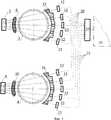
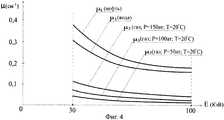
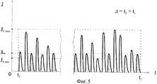
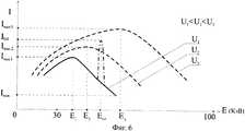
На Фиг.1 представлена функциональная схема анализатора, на Фиг.2 - поперечное сечение корпуса в плоскости, содержащей ось излучения рентгеновской трубки, на Фиг.3 - функциональная схема, поясняющая работу анализатора при измерении скорости, на Фиг.4 - графическая зависимость коэффициентов ослабления рентгеновского излучения от энергии излучения, на Фиг.5 - временнáя последовательность оптических импульсов, вызванных рентгеновскими фотонами с различной энергией, на Фиг.6 - графическая зависимость плотности потока рентгеновских фотонов от их энергии при нескольких значениях напряжения питания рентгеновской трубки, на Фиг.7 - графическая зависимость плотности потока рентгеновских фотонов от их энергии при наличии и при отсутствии наночастиц платины в контролируемом потоке, на Фиг.8 - продольное сечение инжектора металлических частиц, на Фиг.9 - его поперечное сечение, а на Фиг.10 - пример установки инжектора металлических частиц в корпусе.Figure 1 presents a functional diagram of the analyzer, Figure 2 is a cross section of the housing in a plane containing the axis of radiation of the x-ray tube, Figure 3 is a functional diagram explaining the operation of the analyzer when measuring speed, Figure 4 is a graphical dependence of the attenuation coefficients x-ray radiation energy, figure 5 is a temporal sequence of optical pulses caused by x-ray photons with different energies, figure 6 is a graphical dependence of the flux density of x-ray photons energy at several values of the supply voltage of the x-ray tube, Fig.7 is a graphical dependence of the flux density of X-ray photons on their energy in the presence and absence of platinum nanoparticles in a controlled flow, Fig.8 is a longitudinal section of an injector of metal particles, Fig.9 - its cross section, and Fig.10 is an example of the installation of the injector of metal particles in the housing.
На Фигурах введены следующие обозначения: 1 - корпус, 2, 3 и 4 - первая, вторая и третья рентгенопрозрачные вставки соответственно, 5 - рентгеновская трубка, 6 и 7 - первое и второе зеркала соответственно, 8, 9 и 10 - первый, второй и третий первичные коллиматоры соответственно, в каждом из которых выполнены коллимирующие отверстия, 11 - первый многоканальный детектор, 12 и 13 - вторые и третие сцинтилляционные детекторы соответственно, 14, 15 и 16 - первый, второй и третий вторичные коллиматоры соответственно, в каждом из которых выполнены коллимирующие отверстия, 17 - четвертые сцинтилляционные детекторы, 18 - ортогональные коллиматоры, 19, 20, 21 и 22 - первый, второй, третий и четвертый световоды соответственно, 23 - контрольные сцинтилляционные детекторы, 24 - вторичные излучатели, 25 - первый фотоэлектронный преобразователь, 26 - первый модуль обработки, 27 - второй фотоэлектронный преобразователь, 28 - второй модуль обработки, 29 - вычислитель, 30 - модуль управления, 31 - электронный блок, 32 - контроллер режимов, 33 - источник питания, 34 - внешние системы, 35 - инжектор металлических частиц, 36 - датчик давления, 37 - измерительный преобразователь, 38 - суспензия, 39 - поворотный диск, 40 - ось поворотного диска, 41 - червяк, 42 - электропривод, 43 - генератор импульсов, 44 - сальник, 45 - уплотнительная прокладка, 46 - дискриминатор, 47 - первый таймер, 48 - второй таймер, 49 - струевыпрямитель, 50 - нормализатор.The following designations are introduced in the Figures: 1 - case, 2, 3 and 4 - first, second and third radiolucent inserts, respectively, 5 - x-ray tube, 6 and 7 - first and second mirrors, respectively, 8, 9 and 10 - first, second and the third primary collimators, respectively, in each of which collimating holes are made, 11 - the first multichannel detector, 12 and 13 - the second and third scintillation detectors, respectively, 14, 15 and 16 - the first, second and third secondary collimators, respectively, in each of which collimating
Предложенный анализатор содержит корпус 1, представляющий собой отрезок трубопровода с фланцами на его концах, предназначенными для подсоединения корпуса 1 к внешней магистрали.The proposed analyzer contains a housing 1, which is a segment of the pipeline with flanges at its ends, designed to connect the housing 1 to the external highway.
В стенке корпуса 1 установлены рентгенопрозрачные вставки: первая, вторая и третья вставки 2, 3, и 4, например кольцеобразные, выполненные из бериллия.X-ray transparent inserts are installed in the wall of the housing 1: the first, second, and
Низкоэнергетическая рентгеновская трубка 5 установлена таким образом, что ее ось излучения направлена в сторону первой вставки 2 вдоль ее диаметра. Напротив второй и напротив третьей вставок 3 и 4 расположены соответственно второе и первое зеркала 7 и 6, каждое из которых установлено по отношению к плоскости поперечного сечения корпуса под некоторым углом.The low-
На выходе рентгеновской трубки 5 установлены первый, второй и третий первичные коллиматоры 8, 9 и 10 соответственно, с несколькими веером расходящимися коллимирующими отверстиями в каждом. При этом второй первичный коллиматор 9 и третий первичный коллиматор 10 расположены перед первым и перед вторым зеркалами 6 и 7 соответственно. Коллимирующие отверстия в каждом из коллиматоров 9, 10 выполнены таким образом, что оси каждого из них направлены по отношению к плоскости поперечного сечения корпуса под некоторым углом. Угол ориентации зеркал 6 и 7 и угол ориентации коллимирующих отверстий коллиматоров 9 и 10 выбираются таким образом, чтобы отраженные зеркалами пучки рентгеновского излучения пересекали корпус в плоскостях расположения вставок 3 и 4 соответственно.At the output of the
В состав анализатора также входят первый многоканальный детектор 11 и вторые и третие детекторы 12 и 13 соответственно, на входе каждого из которых установлены соответствующие первые, вторые и третие вторичные коллиматоры 14, 15 и 16 соответственно, в каждом из которых содержится несколько коллимирующих отверстий, ось каждого из которых направлена от центра излучения рентгеновской трубки 5 к центру соответствующего детектора, при этом число упомянутых отверстий равно числу соответствующих детекторов. Кроме того, в состав анализатора входят два четвертых детектора 17, два ортогональных коллиматора 18, каждый из которых установлен перед одним из четвертых детекторов 17, а также первый, второй, третий и четвертый световоды 19, 20, 21 и 22 соответственно. В плоскости установки первого многоканального детектора 11 расположены также контрольные детекторы 23, а в каждом, кроме двух крайних, отверстии первого вторичного коллиматора 14 установлен один из вторичных излучателей 24, представляющий собой коллимирующую трубку, выполненную из тяжелого металла, характеристическая линия которого расположена в низкоэнергетической части жесткого рентгеновского диапазона, например из гадолиния или золота.The analyzer also includes a first
Каждый контрольный детектор 23 установлен таким образом, чтобы прямая линия, соединяющая его центр с центром излучения рентгеновской трубки 5, не пересекала первую вставку 2, т.е. проходила снаружи корпуса 1, а каждый из ортогональных коллиматоров 18 расположен в плоскости установки детекторов первого многоканального детектора 11 таким образом, что оси его коллимирующих отверстий расположены под прямым углом к оси излучения рентгеновской трубки 5.Each
Выход каждого из детекторов первого многоканального детектора 11, выход каждого из контрольных детекторов 23 и выход каждого из четвертых детекторов 17 подсоединены к соответствующему каналу первого световода 19, выход каждого из вторых детекторов 12 подсоединен к соответствующему каналу второго световода 20, а выход каждого из третьих детекторов 13 подсоединен к соответствующему каналу третьего световода 21.The output of each of the detectors of the first
Первый световод 19 и четвертый световод 22 подключены каждый своими выходами к соответствующим входам первого фотоэлектронного преобразователя 25, выход которого соединен многоканальной информационной связью со входом первого модуля обработки 26, а второй и третий световоды 20 и 21 соответственно подключены каждый своими выходами к соответствующим входам второго фотоэлектронного преобразователя 27, выход которого соединен многоканальной информационной связью со входом второго модуля обработки 28.The first
Выход первого и выход второго модулей обработки 26 и 28 соответственно подключены каждый к соответствующему входу вычислителя 29, выход которого соединен с модулем управления 30, а дополнительный выход - с генератором импульсов 43. Вычислитель 29, первый и второй модули обработки 26 и 28 соответственно и модуль управления 30 входят в состав электронного блока 31.The output of the first and the output of the second processing modules 26 and 28 are respectively connected each to the corresponding input of the
Предложенный анализатор также содержит контроллер режимов 32, выход которого подключен с помощью многоканальной информационной связи к соответствующему многоканальному входу вычислителя 29, а вход соединен с дополнительным выходом первого модуля обработки 26, и источник питания 33 рентгеновской трубки 5, вход которого подключен к выходу модуля управления 30.The proposed analyzer also contains a mode controller 32, the output of which is connected via multichannel information communication to the corresponding multichannel input of the
Вычислитель 29 содержит выход, подсоединенный ко входу модуля управления 30, и может быть снабжен дополнительным выходом и двусторонней информационной связью для обмена информацией с внешними системами 34.The
Внутри корпуса 1 перед второй вставкой 3 по направлению потока установлен инжектор металлических частиц 35, а в стенке корпуса 1 установлен датчик давления 36, подсоединенный ко входу измерительного преобразователя 37, подключенного к соответствующему многоканальному входу вычислителя 29 с помощью многоканальной информационной связи.Inside the housing 1, before the
Инжектор 35 металлических частиц установлен внутри корпуса 1 в его диаметральном сечении перед второй вставкой 3 по направлению потока и предназначен для подачи в контролируемый поток частиц тяжелого металла. Инжектор 35 металлических частиц может содержать исполнительный механизм, соединенный с электроприводом и установленный внутри баллона, заполненного суспензией 38, содержащей тонкодисперсные частицы металлического порошка, например порошка платины, золота или свинца; в состав суспензии также могут входить нефть, вода и пластификатор, обеспечивающий консистентность суспензии во всем диапазоне рабочей температуры предложенного анализатора. Упомянутый баллон выполнен овальным в поперечном сечении и для уменьшения гидравлического сопротивления установлен в корпусе таким образом, чтобы большая ось овала совпадала с продольной осью корпуса. В стенке баллона выполнены прямоугольные отверстия. Исполнительный механизм инжектора 35 снабжен дисками, установленными таким образом, что часть каждого диска находится внутри баллона, а часть выступает сквозь упомянутое отверстие за его пределы. Поскольку исполнительный механизм должен размещаться внутри уплощенного баллона, все поворотные диски установлены в плоскости его продольного сечения, проходящей через большую ось овала (см. Фиг.8). Каждый из поворотных дисков 39 представляет собой червячное колесо, установленное на оси 40, находящееся в зацеплении с цилиндрическим червяком 41 (см. Фиг.9). Червяк 41 соединен с шаговым электроприводом 42, подключенным к генератору импульсов 43, вход которого соединен с дополнительным выходом вычислителя 29. Для герметизации червяка 41 предусмотрен сальник 44.An
Инжектор 35 металлических частиц установлен внутри корпуса 1 и закреплен на этом корпусе с помощью фланца, снабженного уплотнительной прокладкой 45 (см. Фиг.10).An
В состав предложенного анализатора также входит дискриминатор 46, подключенный с помощью двусторонней многоканальной информационной связи к соответствующему многоканальному входу-выходу вычислителя 29. Вход этого дискриминатора соединен с дополнительным выходом второго модуля обработки 28. Кроме того, в состав анализатора также входят первый таймер 47, выход которого подключен к дополнительному входу первого модуля обработки 26, и второй таймер 48, выход которого соединен с дополнительным входом второго модуля обработки 28; вход первого таймера 47 и вход второго таймера 48 предназначены каждый для подключения к внешним системам 34.The proposed analyzer also includes a discriminator 46 connected via two-way multi-channel information communication to the corresponding multi-channel input-output of the
Внутри корпуса 1 перед инжектором металлических частиц 35 последовательно по направлению потока установлены струевыпрямитель 49 и нормализатор 50 структуры газожидкостного потока.Inside the housing 1, in front of the
Предложенный рентгенофлуоресцентный анализатор состава и скорости трехкомпонентного потока работает следующим образом.The proposed x-ray fluorescence analyzer of the composition and velocity of the three-component flow works as follows.
Поток контролируемой среды, движущейся вдоль корпуса 1 со скоростью W, подвергается предварительной обработке в струевыпрямителе 49 и нормализаторе 50. В струевыпрямителе 49 газожидкостный поток перемешивается с целью повышения его структурной однородности и, прежде всего, с целью устранения локальных вихрей и крупных одиночных пузырей сопутствующего газа. В нормализаторе 50 производится частичная ламинаризация и выравнивание скорости потока.The flow of the controlled medium moving along the housing 1 at a speed W is subjected to preliminary processing in the jet straightener 49 and the normalizer 50. In the straightener 49 the gas-liquid stream is mixed in order to increase its structural homogeneity and, first of all, to eliminate local vortices and large single bubbles of associated gas . In the normalizer 50, partial laminarization and equalization of the flow rate are performed.
При подаче в вычислитель 29 сигнала запуска, например, из внешних систем 34 по двусторонней информационной связи с выхода вычислителя 29 на вход модуля управления 30 поступает команда включения источника питания 33, который включается и запитывает рентгеновскую трубку 5 напряжением, соответствующим номинальному режиму питания, заданному модулем управления 30. В результате на выходе рентгеновской трубки 5 возбуждается и пересекает контролируемую среду, находящуюся в корпусе 1, низкоэнергетическое рентгеновское излучение, пучки которого формируются в каждом из коллимирующих отверстий первого, второго и третьего первичных коллиматоров 8, 9 и 10 соответственно.When a start signal is supplied to the
Упомянутые первичные коллиматоры формируют три группы рентгеновских пучков, веерообразно расходящихся от центра излучения рентгеновской трубки 5 по направлениям к соответствующим отверстиям соответствующего вторичного коллиматора.The mentioned primary collimators form three groups of x-ray beams, fan-shaped diverging from the center of radiation of the
Первая группа веерообразно расходящихся пучков формируется первым первичным коллиматором 8 и лежит в плоскости поперечного сечения В-В корпуса 1, содержащим первую вставку 2 и ось излучения рентгеновской трубки 5; основная часть пучков этой группы за исключением двух крайних пучков пересекает корпус 1 через первую вставку 2, а крайние пучки не пересекают корпус 1 и проходят по воздуху у противоположных сторон корпуса 1 (см. Фиг.2).The first group of fan-shaped diverging beams is formed by the first
Вторая группа веерообразно расходящихся пучков формируется вторым первичным коллиматором 9 и направлена в сторону зеркала 7. Отраженные зеркалом 7 пучки пересекают корпус 1 в сечении А-А, содержащем вторую вставку 3.The second group of fan-shaped diverging beams is formed by the second
Третья группа веерообразно расходящихся пучков формируется третьим первичным коллиматором 10 и направлена в сторону зеркала 6. Отраженные зеркалом 6 пучки пересекают корпус 1 в сечении С-С, содержащем третью вставку 4 (см. Фиг.3).The third group of fan-shaped diverging beams is formed by the third
Каждый из двух крайних рентгеновских пучков первой группы, сформированных в крайних коллимирующих отверстиях первого первичного коллиматора 8 в сечении В-В корпуса 1, попадает, не пересекая корпус 1, в одно из крайних отверстий первого вторичного коллиматора 14 и после формирования в этом отверстии падает на соответствующий ему контрольный детектор 23. Каждый из сформированных первым первичным коллиматором 8 рентгеновских пучков, лежащих в сечении В-В корпуса 1, кроме двух крайних пучков, пересекает первую вставку 2 и контролируемую среду, заполняющую корпус 1, достигает соответствующего ему вторичного излучателя 24, установленного в отверстии первого вторичного коллиматора 14, и после формирования в коллимирующем отверстии этого излучателя падает на один из детекторов многоканального первого детектора 11.Each of the two extreme x-ray beams of the first group formed in the extreme collimating holes of the first
В каждом из контрольных детекторов 23 и в каждом из детекторов многоканального первого детектора 11 формируется оптический сигнал, соответствующий интенсивности принятого рентгеновского излучения. Каждый из сформированных оптических сигналов подается в соответствующий канал первого световода 19 и с соответствующего выхода последнего поступает на соответствующий вход первого фотоэлектронного преобразователя 25.In each of the
Одновременная передача по каналам первого световода 19 нескольких оптических сигналов, выработанных несколькими контрольными детекторами 23 и несколькими детекторами многоканального первого детектора 11, дает возможность использовать для фотоэлектронного преобразования этих сигналов единый многоканальный фотоэлектронный преобразователь - первый фотоэлектронный преобразователь 25.Simultaneous transmission through the channels of the
Такое техническое решение позволяет свести к минимуму разброс коэффициентов преобразования и величин температурных и временных дрейфов нескольких отдельных детекторов и нескольких отдельных фотоэлектронных преобразователей и тем самым минимизировать соответствующую инструментальную погрешность.Such a technical solution allows to minimize the spread of conversion coefficients and the values of temperature and time drifts of several individual detectors and several individual photoelectronic converters and thereby minimize the corresponding instrumental error.
Каждый из рентгеновских пучков, пересекающих контролируемую среду в плоскости расположения первой вставки 2, частично поглощается и рассеивается этой средой, что приводит к уменьшению плотности потока рентгеновских фотонов, падающих на каждый из детекторов первого многоканального детектора 11, и дает возможность оценивать компонентный состав поглощающей среды вдоль линии пересечения по степени уменьшения плотности потока фотонов в сравнении с исходной плотностью этого потока.Each of the x-ray beams crossing the controlled medium in the plane of the location of the
Для получения более детальных данных об объемном компонентном составе следует последовательно облучать контролируемую среду пучками низкоэнергетического рентгеновского излучения, различающимися между собой уровнем энергии, при этом каждый уровень энергии рентгеновского излучения задается соответствующим ему напряжением питания рентгеновской трубки 5. Если, например, необходимо получить, как это показано на Фиг.6, три уровня энергии рентгеновского излучения, следует использовать три значения напряжения питания U1, U2 и U3, обеспечивающих уровни энергии E1(Imax1), E2(Imax2) и Е3(Imax3) соответственно, отвечающие максимальным значениям плотностей потоков фотоновTo obtain more detailed data on the volumetric component composition, it is necessary to sequentially irradiate the controlled medium with low-energy X-ray beams that differ in energy level, while each energy level of the X-ray radiation is set by the corresponding voltage of the
Imax1, Imax2 и Imax3 на выходе рентгеновской трубки 5. Для этого рентгеновская трубка 5 последовательно запитывается напряжениями U1 U2 и U3 от источника питания 33 в соответствии с переключающими сигналами, поступающими на вход этого источника из модуля управления 30 при получении им соответствующих команд из вычислителя 29.Imax1 , Imax2 and Imax3 at the output of the
При облучении контролируемой среды рентгеновским излучением различной энергии в жестком рентгеновском диапазоне 30-100 кэВ изменяется характер поглощения рентгеновских фотонов каждым из компонентов контролируемой среды.When a controlled medium is irradiated with X-rays of various energies in the hard X-ray range of 30-100 keV, the nature of the absorption of X-ray photons by each of the components of the controlled medium changes.
Это объясняется тем, что степень ослабления рентгеновского излучения компонентом контролируемой среды зависит не только от состава этого компонента, но и от энергии излучения, то есть является функцией энергии рентгеновских фотонов, генерируемых рентгеновской трубкой 5 (см. Фиг.4):This is because the degree of attenuation of x-ray radiation by a component of the controlled medium depends not only on the composition of this component, but also on the radiation energy, that is, it is a function of the energy of x-ray photons generated by x-ray tube 5 (see Figure 4):

µ - линейный коэффициент ослабления компонентом контролируемой среды рентгеновского излучения с энергией Е;µ is the linear attenuation coefficient of a component of the controlled X-ray medium with energy E;
Е - энергия рентгеновского излучения.E is the energy of x-ray radiation.
В случае фиксированного уровня энергии рентгеновского излучения линейный коэффициент ослабления падающего пучка конкретным компонентом контролируемой среды является постоянной величиной. Так, например, если выбрать конкретный компонент и зафиксировать определенный уровень энергии излучения, то значение линейного коэффициента ослабления µ будет постоянным.In the case of a fixed level of x-ray energy, the linear attenuation coefficient of the incident beam by a particular component of the controlled medium is a constant. So, for example, if you select a specific component and fix a certain level of radiation energy, then the value of the linear attenuation coefficient µ will be constant.
Таким образом, зависимость степени ослабления плотности потока фотонов заданной энергии конкретным компонентом определяется эффективным линейным размером этого компонента вдоль направления соответствующего рентгеновского пучка (далее по тексту - эффективной толщиной компонента):Thus, the dependence of the degree of attenuation of the photon flux density of a given energy by a specific component is determined by the effective linear size of this component along the direction of the corresponding x-ray beam (hereinafter, the effective thickness of the component):

Y(x) - плотность потока фотонов на входе детектора многоканального первого детектора 11 при заполнении корпуса 1 однокомпонентной контролируемой средой;Y (x) is the photon flux density at the input of the detector of the multichannel
I - плотность потока фотонов на входе детектора многоканального первого детектора 11 при отсутствии в корпусе 1 контролируемой среды;I is the photon flux density at the input of the detector of the multi-channel
е - основание натуральных логарифмов;e - the basis of natural logarithms;
µ - линейный коэффициент ослабления рентгеновского излучения контролируемой средой;µ is the linear attenuation coefficient of x-ray radiation controlled environment;
х - эффективная толщина контролируемой среды.x is the effective thickness of the controlled medium.
Обозначим компоненты контролируемой среды следующим образом: K1 - нефть, K2 - вода и K3 - газ.Denote the components of the controlled environment as follows: K1 - oil, K2 - water and K3 - gas.
При наличии на пути падающего рентгеновского пучка всех трех компонентов: нефти, воды и газа, выражение (2) принимает вид функционального уравнения:If there are all three components on the path of the incident x-ray beam: oil, water and gas, expression (2) takes the form of a functional equation:

Ym1(t) - текущее значение плотности потока фотонов на входе детектора с порядковым номером m первого многоканального детектора 11 при напряжении U1 питания рентгеновской трубки 5 и при наличии в корпусе 1 трехкомпонентной контролируемой среды;Ym1 (t) is the current value of the photon flux density at the input of the detector with serial number m of the first
x1, x2 и х3 - эффективные толщины компонентов K1, K2 и K3 контролируемой среды соответственно;x1 , x2 and x3 are the effective thicknesses of the components K1 , K2 and K3 of the controlled medium, respectively;
µ1(Eq), µ2(Eq) и µ3(Eq) - линейные коэффициенты ослабления рентгеновских излучений с фиксированной энергией Eq каждым из компонентов K1, K2 и K3;µ1 (Eq ), µ2 (Eq ) and µ3 (Eq ) are the linear attenuation coefficients of x-rays with a fixed energy Eq by each of the components K1 , K2 and K3 ;
Im1(t) - текущее значение плотности потока фотонов на входе детектора с порядковым номером m, входящего в состав первого многоканального детектора 11, при напряжении U1 питания рентгеновской трубки 5 и при отсутствии в корпусе 1 контролируемой среды;Im1 (t) is the current value of the photon flux density at the input of the detector with serial number m, which is part of the first
t - текущее время.t is the current time.
Последовательно подставляя в уравнение (3) значения линейных коэффициентов ослабления, соответствующие нескольким, например трем, значениям энергии излучения Eq=Е1, Eq=Е2, Eq=Е3, а именно значения µi(E1), µi(Е2) и µi(E3), где i=1, 2, 3, получим для каждого рентгеновского пучка, лежащего в плоскости расположения первой вставки 2, три системы функциональных уравнений вида (3) с тремя численными неизвестными х1, х2, х3 и тремя функциональными неизвестными µ1(Eq), µ2(Eq), µ3(Eq).Subsequently, substituting into equation (3) the values of linear attenuation coefficients corresponding to several, for example, three, values of the radiation energy Eq = E1 , Eq = E2 , Eq = E3 , namely, the values of μi (E1 ), μi (E2 ) and µi (E3 ), where i = 1, 2, 3, we obtain for each x-ray beam lying in the plane of the
В случае когда текущее значение параметра Im1(t) известно, то есть когда оно непрерывно измеряется, когда конкретное значение энергии излучения Eq=Е1, Eq=Е2, Eq=Е3 зафиксировано, а также когда определены и занесены в память первого модуля обработки 26 экспериментальные зависимости линейных коэффициентов ослабления от энергии излучения µ1(Eq), µ2(Eq), µ3(Eq), решение систем функциональных уравнений вида (3) в вычислителе 29 позволяет получить значения эффективных толщин x1, x2, иIn the case when the current value of the parameter Im1 (t) is known, that is, when it is continuously measured, when the specific value of the radiation energy Eq = E1 , Eq = E2 , Eq = E3 is fixed, as well as when it is determined and entered in memory of the first processing module 26, the experimental dependences of the linear attenuation coefficients on the radiation energy μ1 (Eq ), μ2 (Eq ), μ3 (Eq ), solving systems of functional equations of the form (3) in
х3 каждого из компонентов K1, K2 и K3 соответственно вдоль линии пересечения контролируемой среды одним из падающих рентгеновских пучков и тем самым определить объемную долю каждого из этих компонентов в поперечном сечении контролируемого потока вдоль направления упомянутого пучка. После определения эффективных толщин x1, x2, и х3 нефти, воды и газа соответственно вдоль каждого из рентгеновских пучков, падающих на один из m детекторов первого многоканального детектора 11, в вычислителе 29 производится контроль достоверности полученных значений эффективных толщин, для чего используется контрольное условие:x3 of each of the components K1 , K2 and K3, respectively, along the line of intersection of the controlled medium by one of the incident X-ray beams and thereby determine the volume fraction of each of these components in the cross section of the controlled flow along the direction of the mentioned beam. After determining the effective thicknesses x1 , x2 , and x3 of oil, water and gas, respectively, along each of the x-ray beams incident on one of the m detectors of the first

l - длина хорды, стягивающей дугу окружности радиуса R вдоль соответствующего рентгеновского пучка;l is the length of the chord, tightening the arc of a circle of radius R along the corresponding x-ray beam;
R - внутренний радиус корпуса 1.R is the inner radius of the housing 1.
Для центрального рентгеновского пучка, направленного вдоль оси излучения рентгеновской трубки 5, длина l упомянутой хорды составляет l=2R, для всех других пучков она меньше указанного значения: l<2R.For the central x-ray beam directed along the radiation axis of the
Операции решения системы функциональных уравнений вида (3) относительно искомых величин x1, х2 и х3 выполняются в вычислителе 29.The operations of solving the system of functional equations of the form (3) with respect to the desired quantities x1 , x2 and x3 are performed in the
Параметр Im1(t) упомянутых функциональных уравнений характеризует текущее значение плотности потока фотонов на входе соответствующего детектора первого многоканального детектора 11 при отсутствии в корпусе 1 контролируемой среды.The parameter Im1 (t) of the mentioned functional equations characterizes the current value of the photon flux density at the input of the corresponding detector of the first
Поскольку при эксплуатации предложенного анализатора контролируемая среда всегда заполняет корпус 1, обеспечить состояние «при отсутствии контролируемой среды» весьма затруднительно. В тоже время в процессе эксплуатации предложенного анализатора текущее значение параметра Im1(t) может существенно изменяться по величине относительно своего номинального значения, измеренного и введенного в память первого модуля обработки 26 при юстировке предложенного анализатора.Since during the operation of the proposed analyzer the controlled environment always fills the housing 1, it is very difficult to ensure the state “in the absence of a controlled environment”. At the same time, during operation of the proposed analyzer, the current value of the parameter Im1 (t) can significantly change in magnitude relative to its nominal value, measured and entered into the memory of the first processing module 26 when adjusting the proposed analyzer.
Изменение текущего значения параметра Im1(t) может происходить, например, в связи с износом катода рентгеновской трубки 5, изменением напряжения ее питания, смещением пространственного положения рентгеновской трубки 5 относительно начального положения и т.п. Для того чтобы уменьшить влияние указанных факторов на точность измерения компонентного состава, определение текущего значения параметра Im1(t) в процессе эксплуатации производится не прямым методом - по информации, формируемой детекторами первого многоканального детектора 11, а косвенно - на основании информации, вырабатываемой контрольными детекторами 23. При этом принимается во внимание, что коэффициенты передачи отдельных детекторов, входящих в состав первого многоканального детектора 11, и коэффициенты передачи контрольных детекторов 23 в случае, когда их сцинтиллирующие кристаллы принадлежат одной партии изготовления, практически не отличаются между собой по величине и одинаково изменяются как во времени, так и под действием внешних дестабилизирующих факторов. В этом случаеA change in the current value of the parameter Im1 (t) can occur, for example, due to wear of the cathode of the


Im1(t) - текущее значение сигнала на выходе детектора с порядковым номером m, входящего в состав первого многоканального детектора 11, при напряжении U1 питания рентгеновской трубки 5, пропорциональное текущему значению плотности потока фотонов на входе этого детектора при отсутствии в корпусе 1 контролируемой среды;Im1 (t) is the current value of the signal at the output of the detector with serial number m, which is part of the first
Im1 - начальное значение упомянутого сигнала;Im1 is the initial value of said signal;
In1(t) - текущее значение сигнала на выходе одного из двух контрольных детекторов 23 при напряжении U1 питания рентгеновской трубки 5, пропорциональное текущему значению плотности потока фотонов на входе этого детектора;In1 (t) is the current value of the signal at the output of one of the two
In1 - начальное значение упомянутого сигнала;In1 is the initial value of said signal;
t - текущее время.t is the current time.
Численное значение каждого из сигналов In1(t) и In1 в выражении (5) определяется в первом модуле обработки 26 как среднеарифметическое значение двух оптических сигналов, каждый из которых вырабатывается одним из контрольных детекторов 23, передается по соответствующему каналу световода 19 на вход первого фотоэлектронного преобразователя 25 и после оптоэлектронного преобразования в этом преобразователе поступает в электронной форме по многоканальной информационной связи на вход первого модуля обработки 26.The numerical value of each of the signals In1 (t) and In1 in expression (5) is determined in the first processing unit 26 as the arithmetic mean of two optical signals, each of which is generated by one of the
Поскольку рентгеновское излучение, падающее на каждый из контрольных детекторов 23, пересекает только воздушную среду, поглощением и рассеянием в которой при энергиях излучения более 30 кэВ можно пренебречь, оптические сигналы, формируемые этими детекторами, не зависят от состава пропускающей среды, определяются только характеристиками излучения рентгеновской трубки 5 и могут использоваться в качестве контрольных сигналов In1 и In1(t).Since the x-ray radiation incident on each of the
Начальное значение In1 контрольного сигнала измеряется в процессе юстировки предложенного анализатора и вносится в память первого модуля обработки 26. Кроме того, в процессе юстировки измеряются и вносятся в память первого модуля обработки 26 начальные значения сигналов I11, I21, … Im1, где m=1, 2…, 5, каждое из которых соответствует одному из детекторов первого многоканального детектора 11 при напряжении U1 питания рентгеновской трубки 5. В память упомянутого модуля также вносятся значения сигналов I12, I22, …, Im2 и I13, I23, …, Im3, соответствующие напряжениям питания U2 и U3 рентгеновской трубки 5. При работе анализатора в первый модуль обработки 26 непрерывно поступает информация о текущем значенииThe initial value In1 of the control signal is measured during the adjustment of the proposed analyzer and is stored in the memory of the first processing module 26. In addition, during the adjustment, the initial values of the signals I11 , I21 , ... Im1 are measured and stored in the memory of the first processing module 26, m = 1, 2 ..., 5, each of which corresponds to one of the detectors of the first
In1(t) контрольного сигнала на выходе каждого из контрольных детекторов 23.In1 (t) of the control signal at the output of each of the
На основе этой информации с использованием хранящихся в памяти первого модуля обработки 26 данных о значениях In1 и Im1 вычисляется, в соответствии с выражением (5), и передается в вычислитель 29 текущее значение параметра Im1(t).Based on this information, using the data stored in the memory of the first processing module 26, the values of In1 and Im1 are calculated, in accordance with expression (5), and the current value of the parameter Im1 (t) is transmitted to the
Из (3) и (5) имеем:From (3) and (5) we have:

каждое из обозначений соответствует обозначениям, принятым в выражениях (3) и (5).each of the designations corresponds to the designations adopted in expressions (3) and (5).
Параметры µ1(Eq), µ2(Eq) и µ3(Eq) уравнения (6) представляют собой функциональные неизвестные, значения которых определяются в первом модуле обработки 26 на основе введенных в его память экспериментальных данных о взаимосвязи значения линейного коэффициента ослабления µ рентгеновского излучения с энергией Eq, отмасштабированной по реперному значению энергии.The parameters μ1 (Eq ), μ2 (Eq ) and μ3 (Eq ) of equation (6) are functional unknowns whose values are determined in the first processing module 26 based on the experimental data on the relationship between the linear attenuation coefficient µ of X-ray radiation with an energy Eq scaled by a reference energy value.
Экспериментально полученные графические зависимости линейных коэффициентов ослабления рентгеновского излучения µ1, µ2 и µ3 каждым из компонентов контролируемой среды K1, K2 и K3 - нефтью, водой и газом соответственно, от энергии Е рентгеновского излучения представлены на Фиг.4. Как видно из этих графиков, упомянутые зависимости существенно нелинейны, поэтому для корректного решения функционального уравнения (6) необходимо учитывать не только интегральную характеристику рентгеновского излучения - плотность потока его фотонов I, но и дифференциальную характеристику - распределение рентгеновских фотонов по энергиям Е.The experimentally obtained graphical dependences of the linear attenuation coefficients of x-ray radiation μ1 , μ2 and μ3 by each of the components of the controlled medium K1 , K2 and K3 - oil, water and gas, respectively, on the energy E of the x-ray radiation are presented in Figure 4. As can be seen from these graphs, the above dependences are essentially nonlinear, therefore, for the correct solution of functional equation (6), it is necessary to take into account not only the integral characteristic of X-ray radiation - the flux density of its photons I, but also the differential characteristic - the distribution of X-ray photons by energy E.
Диаграмма распределения во времени рентгеновских фотонов с различными энергиями, принятых одним из детекторов первого многоканального детектора 11 за некоторый фиксированный промежуток времени Δt=t2-t1, приведена на Фиг.5.The time distribution diagram of x-ray photons with different energies received by one of the detectors of the first
Данная диаграмма представляет собой временную последовательность немасштабированных по амплитуде оптических импульсов различной интенсивности J, каждый из которых сформирован одним из детекторов первого многоканального детектора 11 при падении на его вход соответствующего рентгеновского фотона; интенсивность J такого импульса пропорциональна энергии соответствующего фотона в жестком диапазоне рентгеновского излучения.This diagram is a time sequence of non-amplitude-amplified optical pulses of various intensities J, each of which is formed by one of the detectors of the first
При достаточно большом числе S импульсов, выработанных каждым из детекторов первого многоканального детектора 11 за промежуток времени Δt=t2-t1, в первом модуле обработки 26 моделируется представленная на Фиг.6 дифференциальная характеристика рентгеновского излучения - зависимость плотности потока фотонов I от энергии фотонов Е при каждом из напряжений питания U1, U2 и U3 рентгеновской трубки 5. Промежуток времени Δt, в течение которого формируется количество S упомянутых импульсов, обычно называется временем экспозиции.With a sufficiently large number S of pulses generated by each of the detectors of the first
Для количественного масштабирования качественных зависимостей, представленных на Фиг.5 и на Фиг.6, необходимо сформировать реперное значение энергии, используя для этого достоверно определяемые параметры рентгеновских фотонов. Реперное значение энергии в предложенном анализаторе формируется с помощью вторичных излучателей 24.For quantitative scaling of the qualitative relationships presented in FIG. 5 and FIG. 6, it is necessary to generate a reference energy value using reliably determined parameters of x-ray photons. The reference value of energy in the proposed analyzer is formed using
Каждый вторичный излучатель 24 представляет собой установленную в отверстии первого вторичного коллиматора 14 коллимирующую трубку, изготовленную из тяжелого металла с ярко выраженной характеристической линией спектра излучения, лежащей в диапазоне энергий 30-100 кэВ, например из гадолиния или платины. Так как для работы дискриминатора 46 помимо характеристической линии, формируемой вторичным излучателем, требуется еще и отличная от нее характеристическая линия, формируемая металлической частицей инжектора 35, необходимо использовать два различных тяжелых металла, например гадолиний для дискриминатора 46 и платину для инжектора 35.Each
При прохождении рентгеновского пучка сквозь упомянутую трубку фотоны пучка могут возбуждать флуоресценцию атомов гадолиния, расположенных в приповерхностном слое коллимирующего отверстия трубки, сопровождаемую возникновением вторичного характеристического излучения. Возбуждение флуоресценции происходит только в том случае, когда энергии


ω - круговая частота возбуждающих фотонов;ω is the circular frequency of exciting photons;
Eo - энергия характеристического излучения.Eo is the energy of characteristic radiation.
Спектр характеристического излучения является линейчатым; характеристической линии гадолиния в этом спектре соответствует энергия излученияThe spectrum of characteristic radiation is ruled; the gadolinium characteristic line in this spectrum corresponds to the radiation energy
EGd=42,996 кэВ.EGd = 42.996 keV.
Если энергия возбуждающих фотонов существенно превосходит энергию характеристического возбуждения атомов гадолиния:If the energy of exciting photons significantly exceeds the energy of characteristic excitation of gadolinium atoms:

то плотность потока характеристических фотонов с уровнем энергии Eo существенно превосходит плотности потока фотонов с другими значениями энергии.then the flux density of characteristic photons with an energy level Eo significantly exceeds the flux density of photons with other energy values.
Поэтому при наложении на излучение рентгеновской трубки 5, характеризуемое непрерывным спектром, характеристического излучения, имеющего линейчатый спектр, существенно изменяется характер распределения I(Е) плотности потока рентгеновских фотонов по энергиям на входе каждого из детекторов первого многоканального детектора 11 (см. Фиг.6).Therefore, when applying to the radiation of the
При отсутствии характеристического излучения распределение I(Е) представляет собой в жестком рентгеновском диапазоне убывающую кривую, представленную на Фиг.6 сплошной линией.In the absence of characteristic radiation, the distribution of I (E) is a decreasing curve in the hard X-ray range, shown in Fig. 6 by a solid line.
При наличии характеристического излучения с энергией фотонов Е=EGd в упомянутом распределении возникает представленный на Фиг.6 штрихпунктирной линией локальный максимум плотности потока фотонов IGd=I(EGd), где EGd - энергия возбуждения атомов гадолиния. Уровень этого максимума существенно превосходит наибольший уровень плотности потока фотонов Imax1 при всех других значениях энергии, отличающихся от значения Eo:In the presence of characteristic radiation with photon energy E = EGd in the above distribution, a local maximum of the photon flux density IGd = I (EGd ), shown in FIG. 6, appears, where EGd is the excitation energy of gadolinium atoms. The level of this maximum significantly exceeds the highest level of photon flux density Imax1 for all other energy values that differ from the value of Eo :
IGd>Imax1.IGd > Imax1 .
Возникновение локального максимума плотности потока фотонов IGd при характеристическом значении Eo энергии объясняется тем, что значительное число первичных рентгеновских фотонов, распределенных в широком диапазоне энергии от Eo до Emax, поглощается атомами гадолиния, порождающими поток такого же числа вторичных флуоресцентных фотонов, сосредоточенных в весьма узкой энергетической области вблизи характеристического значения энергии Eo=EGd. Поскольку все вторичные фотоны пересекают только воздушную среду, поглощением и рассеянием в которой можно пренебречь, практически все они достигают детекторов первого многоканального детектора 11 и обеспечивают на их входах высокую локальную плотность потока фотонов с характеристическим значением энергии EGd.The occurrence of a local maximum of the photon flux density IGd at a characteristic value of Eo energy is explained by the fact that a significant number of primary X-ray photons distributed in a wide energy range from Eo to Emax are absorbed by gadolinium atoms, which generate a flux of the same number of secondary fluorescent photons concentrated in a very narrow energy region near the characteristic energy value Eo = EGd . Since all secondary photons cross only the air medium, in which absorption and scattering can be neglected, almost all of them reach the detectors of the first
Каждому фотону с энергией EGd, поглощенному детектором первого многоканального детектора 11, отвечает формируемый на выходе этого детектора световой импульс интенсивностью JGd (см. Фиг.5), передаваемый по соответствующему каналу первого световода 19 на вход первого фотоэлектронного преобразователя 25, где он преобразуется в электрический импульс, поступающий по многоканальной информационной связи в первый модуль обработки 26.Each photon with energy EGd absorbed by the detector of the first
Поскольку интенсивность оптического импульса и, соответственно, амплитуда соответствующего ему электрического импульса пропорциональны энергии поглощенного фотона, возникает возможность обнаружения в первом модуле обработки 26 наличия фотонов с характеристическим значением энергии EGd по частоте появления электрических импульсов одной и той же амплитуды. Способ обнаружения упомянутых фотонов поясняется временнóй последовательностью J(t) оптических импульсов, представленной на Фиг.5.Since the intensity of the optical pulse and, accordingly, the amplitude of the corresponding electric pulse are proportional to the energy of the absorbed photon, it becomes possible to detect in the first processing module 26 the presence of photons with a characteristic value of energy EGd by the frequency of occurrence of electric pulses of the same amplitude. A method for detecting said photons is illustrated by the time sequence J (t) of optical pulses shown in FIG. 5.
Анализ этой временной последовательности показывает, что наиболее часто по сравнению с другими встречаются импульсы интенсивности JGd, заштрихованные на Фиг.5. Эти импульсы соответствуют характеристическим фотонам с энергией EGd и создают на кривой I(E) (Фиг.6) локальный максимум плотности потока фотонов IGd в точке Е=EGd.The analysis of this time sequence shows that, most often, pulses of intensity JGd , shaded in FIG. 5, are encountered in comparison with others. These pulses correspond to characteristic photons with energy EGd and create on the curve I (E) (Fig.6) a local maximum of the photon flux density IGd at the point E = EGd .
Наличие локального максимума IGd позволяет объективно выделить из общего числа фотонов различной энергии группу фотонов с энергией ЕGd и тем самым обозначить на оси энергий Е графика I(E) Фиг.6 точную масштабную отметку EGd=42,996 кэВ, позволяющую достоверно отмасштабировать весь график I(E) по значениям энергий.The presence of a local maximum IGd allows you to objectively select from the total number of photons of different energies a group of photons with energy EGd and thereby designate the exact scale mark EGd = 42.996 keV on the axis of the energies E of Fig. 6, which allows you to reliably scale the entire graph I (E) in terms of energies.
Исходя из изложенного для решения в вычислителе 29 уравнения (6) предварительно вычисляются в первом модуле обработки 26 численные значения каждого из параметров µ1(Eq), µ2(Eq) и µ3(Eq) для нескольких фиксированных значений энергии Е=Е1, E2,...,Eq,..., каждое из которых соответствует узкой энергетической полосе шириной 2ΔЕ, содержащей не менее числа s фотонов, а именно численные значенияBased on the above, for solving in

µ1, µ2 и µ3 - линейные коэффициенты ослабления излучения соответственно нефтью, водой и газом;µ1 , µ2 and µ3 - linear attenuation coefficients of radiation, respectively, oil, water and gas;
Eq - фиксированное значение энергии излучения;Eq is a fixed value of the radiation energy;
ΔЕ - разность двух последовательных фиксированных значений энергии излучения.ΔЕ is the difference of two consecutive fixed values of the radiation energy.
Количественные значения параметров µ(Eq) вычисляются в первом модуле обработки 26 на основе заложенных в его память численных данных, соответствующих приведенным на Фиг.4 экспериментальным зависимостям каждого из коэффициентов µ1 µ2 и µ3 от энергии излучения Е. При этом для уменьшения погрешности вычисления при выборе численных данных выбираются возможно более узкие энергетические полосы шириной 2ΔЕ.Quantitative values of the parameters μ (Eq ) are calculated in the first processing module 26 on the basis of numerical data stored in its memory corresponding to the experimental dependences of each of the coefficients μ1 μ2 and μ3 shown in Fig. 4 and the radiation energy E. Moreover, to reduce calculation errors when choosing numerical data, as narrow as possible energy bands with a width of 2ΔE are selected.
Для надежного формирования каждого значения плотности потока фотонов, усредненного на энергетической полосе шириной 2ΔЕ, необходимо получить за время экспозиции Δt не менее числа s=100 фотонов.For reliable formation of each photon flux density averaged over an energy strip with a width of 2ΔE, it is necessary to obtain at least the number s = 100 photons during the exposure time Δt.
Численное значение времени экспозиции Δt выбирается и вводится в память первого таймера 47 исходя из двух противоречивых условий.The numerical value of the exposure time Δt is selected and entered into the memory of the first timer 47 based on two conflicting conditions.
Во-первых, оно должно быть, по возможности, большим, для того чтобы обеспечить поглощение каждым детектором многоканального детектора 11 достаточно большого числа S рентгеновских фотонов, необходимого для достоверного вычисления в первом модуле обработки 26 усредненных значений плотности потоков фотонов в каждой из энергетических полос Eq±ΔЕ в диапазоне энергий от 30 до 100 кэВ.First, it should be as large as possible in order to ensure that each detector of the
Во-вторых, оно должно быть, по возможности, малым, для того чтобы компонентный состав контролируемой среды, непрерывно протекающей сквозь подконтрольную область корпуса 1, не успел существенно измениться за время экспозиции.Secondly, it should be as small as possible, so that the component composition of the controlled environment, continuously flowing through the controlled area of the housing 1, does not have time to change significantly during the exposure.
В соответствии с указанными условиями значение времени экспозиции устанавливается исходя из максимальной скорости контролируемого потока и эффективного размера подконтрольной области:In accordance with the specified conditions, the exposure time value is set based on the maximum speed of the controlled flow and the effective size of the controlled area:

Δt - время экспозиции;Δt is the exposure time;
а - эффективный размер подконтрольной области, равный размеру первой вставки 2 по направлению контролируемого потока;a is the effective size of the control area, equal to the size of the
Wm - наибольшее значение продольной составляющей скорости контролируемого потока.Wm - the largest value of the longitudinal component of the speed of the controlled flow.
Для обеспечения требуемой точности измерения параметров контролируемого потока необходимо определить минимально возможное время экспозиции, достаточное для получения надежной информации о компонентном составе контролируемого потока. В свою очередь, это время зависит от числа S рентгеновских фотонов с энергией от 30 до 100 кэВ, принятых каждым из детекторов первого многоканального детектора 11. Поскольку в соответствии с (9) численные значения коэффициентов µ1(Eq), µ2(Eq) и µ3(Eq), характеризующих компонентный состав потока, вычисляются в узких энергетических полосах шириной 2ΔЕ, число S определяется как сумма чисел s рентгеновских фотонов с энергией от (Eq-ΔЕ) до (Eq+ΔЕ), принятых каждым из детекторов первого многоканального детектора 11 за минимально возможное время экспозиции, т.е.:To ensure the required accuracy of measuring the parameters of the controlled flow, it is necessary to determine the minimum possible exposure time sufficient to obtain reliable information about the component composition of the controlled flow. In turn, this time depends on the number S of X-ray photons with energies from 30 to 100 keV received by each of the detectors of the first

S - число рентгеновских фотонов, падающих на каждый детектор первого многоканального детектора 11 за время экспозиции Δt;S is the number of x-ray photons incident on each detector of the first
q=1, 2, 3,… - натуральное число, равное порядковому номеру энергетической полосы;q = 1, 2, 3, ... is a natural number equal to the ordinal number of the energy band;
s - число фотонов, энергии которых находятся в энергетической полосе шириной 2ΔEq.s is the number of photons whose energies are in an energy band 2ΔEq wide.
Практически, с учетом числа s=100,In practice, given the number s = 100,

Указанное в условии (12) число S рентгеновских фотонов должно приниматься каждым детектором первого многоканального детектора 11 за время экспозиции Δt, наименьшее численное значение которого при скорости контролируемой среды Wm≤10 м/с и продольном размере первой вставки а≤5 мм, в соответствии с (10), задается условиемThe number S of X-ray photons specified in condition (12) must be received by each detector of the first

Δtmin - минимально возможное время экспозиции, обеспечивающее прием каждым из детекторов первого многоканального детектора 11 числа S≥5·105 рентгеновских фотонов. Приведенные в неравенствах (12) и (13) численные значения параметров S и Δtmin наряду с числом m детекторов первого многоканального детектора 11 полностью определяют параметры генерации рентгеновской трубки 5 и, кроме того, характеризуют требуемую информационную производительность процессоров, входящих в состав первого модуля обработки 26 и вычислителя 29. При определении состава контролируемой среды с высоким газосодержанием в вычислителе 29 необходимо учитывать текущие значения P(t) давления, поскольку зависимость от давления линейного коэффициента µ3 ослабления рентгеновского излучения газом при высоких давлениях в корпусе 1 весьма существенна (см. Фиг.4). Так, например, если при нормальных климатических условиях: Р0=1 ат, Т0=20°С величина линейного коэффициента µ3 для газа существенно меньше величин линейных коэффициентов µ1 и µ2 для нефти и воды соответственно, то при значениях давления P(t)=10-100 ат величина коэффициента µ3 становится соизмеримой с величинами коэффициентов µ1 иΔtmin - the minimum possible exposure time, ensuring each detector of the first
µ2.µ2 .
Поэтому при давлениях P(t)>10 ат в выражении (6) вместо коэффициента µ3(Eq), соответствующего нормальным климатическим условиям, следует использовать коэффициент µ3(Eq, P, T), соответствующий фактическому значению давления контролируемой среды в корпусе 1 при нормальной температуре Т:Therefore, at pressures P (t)> 10 atm in expression (6), instead of the coefficient μ3 (Eq ) corresponding to normal climatic conditions, the coefficient μ3 (Eq , P, T) should be used, which corresponds to the actual value of the pressure of the controlled medium in case 1 at normal temperature T:

все обозначения, кроме µ3(Eq, Р, Т), соответствуют обозначениям, использованным в выражении (6);all designations except µ3 (Eq , P, T) correspond to the designations used in expression (6);
µ3(Eq, Р, Т) - линейный коэффициент ослабления рентгеновского излучения компонентом K3 (газом) при энергии излучения Eq, давлении контролируемой среды Р и нормальной температуре контролируемой среды Т.µ3 (Eq , P, T) is the linear attenuation coefficient of X-ray radiation by component K3 (gas) at radiation energy Eq , pressure of the controlled medium P and normal temperature of the controlled medium T.
Значения линейного коэффициента µ3(Eq, Р, Т) вычисляются в вычислителе 29 за промежуток времени Δtmin=t2-t1 причем сигналы о моменте времени t1 начала вычислений и моменте времени t2 окончания вычислений поступают на дополнительный вход первого модуля обработки 26 с выхода первого таймера 47, в память которого из внешних систем 34 введено численное значение параметра Δtmin, соответствующее неравенству (13), и передаются в вычислитель 29 с выхода первого модуля обработки 26. При этих вычислениях используются введенные в память вычислителя 29 из внешних систем 34 экспериментально полученные численные данные о зависимости величины линейного коэффициента µ3 от энергии излучения Eq при нескольких фиксированных значениях давления Р при нормальной температуре Т (см. Фиг.4), справочные данные о значениях коэффициента сжимаемости β3, а также измерительная информация о текущих значениях давления P(t), сформированная датчиком давления 36, преобразованная в цифровую форму в измерительном преобразователе 37 и переданная в вычислитель 29 по многоканальной информационной связи с выхода упомянутого измерительного преобразователя.The values of the linear coefficient μ3 (Eq , P, T) are calculated in the
Решение функционального уравнения (14) для каждого из трех значений U1, U2, U3 напряжения питания рентгеновской трубки 5 и для каждого из m=1, 2, …5 рентгеновских пучков, принимаемых детекторами первого многоканального детектора 11, производится в вычислителе 29 за время экспозиции, Δtmin, соответствующее неравенству (13).The solution of functional equation (14) for each of the three values U1 , U2 , U3 of the supply voltage of the
Совокупность решений функциональных уравнений (14) при различных значениях напряжения U=U1, U2, U3 питания рентгеновской трубки 5 для каждого из m=1, 2, …5 рентгеновских пучков позволяет получить в вычислителе 29 и передать по соответствующей двусторонней многоканальной информационной связи во внешние системы 34 детальную количественную информацию об относительном содержании в единицах объема каждого из трех компонентов контролируемой среды: нефти, воды и газа по всему поперечному сечению контролируемого потока:The set of solutions of functional equations (14) for various voltage values U = U1 , U2 , U3 of the power supply of the

V1(t) - текущее значение объемной доли компонента K1 (нефти);V1 (t) is the current value of the volume fraction of the component K1 (oil);
V2(t) - текущее значение объемной доли компонента K2 (воды);V2 (t) is the current value of the volume fraction of the component K2 (water);
V3(t) - текущее значение объемной доли компонента K3 (газа);V3 (t) is the current value of the volume fraction of the component K3 (gas);
t - текущее время.t is the current time.
Для получения данных о компонентном составе контролируемой среды в единицах массы необходимо использовать дополнительную информацию, которая вырабатывается четвертыми детекторами 17.To obtain data on the component composition of the controlled medium in mass units, it is necessary to use additional information that is generated by the
Оптические сигналы, снимаемые с выходов четвертых детекторов 17, вырабатываются этими детекторами под воздействием рассеянного рентгеновского излучения, представляющего собой вторичное излучение, возникающее в результате упругого рассеяния контролируемой средой первичного излучения рентгеновской трубки 5. Рассеянное рентгеновское излучение направлено, в основном, под большими углами к направлению первичного излучения, близкими к прямым углам. Поэтому на каждый из четвертых детекторов 17, установленных в плоскости расположения первой вставки 2 на линии, нормальной оси излучения рентгеновской трубки 5, падает, в основном, рассеянное излучение. Для полного исключения возможности попадания на вход четвертых детекторов 17 первичного излучения рентгеновской трубки 5 перед каждым из них установлен ортогональный коллиматор 18, содержащей несколько коллимирующих отверстий, оси которых параллельны между собой и направлены под прямым углом к оси излучения рентгеновской трубки 5, а глубина каждого отверстия существенно превышает его диаметр:Optical signals taken from the outputs of the
b/d>>1, гдеb / d >> 1, where
b - глубина коллимирующего отверстия;b is the depth of the collimating hole;
d - диаметр коллимирующего отверстия.d is the diameter of the collimating hole.
Поскольку интенсивность рассеянного излучения в жестком рентгеновском диапазоне энергий до 100 кэВ определяется, в основном, плотностью рассеивающей среды и слабо зависит от интенсивности первичного излучения рентгеновской трубки 5, оптический сигнал, формируемый каждым из двух четвертых детекторов 17, пропорционален текущему значению средней плотности ρ(t) контролируемой среды.Since the intensity of the scattered radiation in the hard X-ray energy range up to 100 keV is determined mainly by the density of the scattering medium and weakly depends on the intensity of the primary radiation of the
После преобразования в электрический цифровой код упомянутый сигнал поступает в вычислитель 29, где на основании принятой информации о текущем значении средней плотности ρ(t) контролируемой среды и ранее вычисленных данных (15) о текущих значениях объемных долей каждого из ее компонентов определяются текущие значения относительного содержания каждого из компонентов газожидкостного потока в единицах массы:After conversion to an electric digital code, the signal is sent to a

M1(t) - текущее значение массовой доли компонента K1 (нефти);M1 (t) is the current value of the mass fraction of the component K1 (oil);
M2(t) - текущее значение массовой доли компонента K2 (воды);M2 (t) is the current value of the mass fraction of the component K2 (water);
M3(t) - текущее значение массовой доли компонента K3 (газа);M3 (t) is the current value of the mass fraction of the component K3 (gas);
t - текущее время.t is the current time.
Текущие значения (16) массового содержания компонентов необходимы для определения в вычислителе 29 текущих значений покомпонентного массового расхода QM1(t), QM2(t) и QM3(t) каждого из трех компонентов газожидкостного потока - нефти, воды и газа соответственно.The current values (16) of the mass content of the components are necessary for determining in the
Так как помимо текущего значения массовой доли нефти M1(t) дебит нефти традиционно принято оценивать также и в объемных единицах (баррелях), в вычислителе 29 определяется номинальная объемная доля нефти, т.е. объемная доля, приведенная к нормальным климатическим условиям.Since in addition to the current value of the mass fraction of oil M1 (t), the oil production rate is traditionally also estimated in volume units (barrels), the nominal volume fraction of oil is determined in
Для вычисления текущего значения номинальной объемной доли нефти в вычислителе 29 используется дополнительная информация о текущем значении давления P(t) контролируемой среды, сформированная датчиком давления 36, переданная с выхода этого датчика на вход измерительного преобразователя 37 и с выхода последнего по многоканальной информационной связи на соответствующий многоканальный вход вычислителя 29.To calculate the current value of the nominal oil volume fraction in the
В вычислителе 29 на основе принятого сигнала о текущем значении P(t) производится приведение ранее вычисленной объемной доли нефти V1(t) к нормальному давлению Р0=1 ат при нормальной температуре Т0=20°С с учетом хранящихся в памяти вычислителя 29 справочных данных о значении коэффициента сжимаемости β1 нефти. В результате этой операции в вычислителе 29 определяется текущее значение номинальной объемной доли нефти:In the

V01(t) - текущее значение объемной доли компонента K1 (нефти), приведенное к нормальным климатическим условиям;V01 (t) - the current value of the volume fraction of the component K1 (oil), reduced to normal climatic conditions;
t - текущее время.t is the current time.
Для измерения скорости W газожидкостного потока в предложенном анализаторе выбран автокорреляционный метод. При этом в зависимости от режима контролируемого потока, определяемого контроллером режимов 32, для измерения скорости используется либо информация о движении естественной локальной неоднородности потока, либо информация о движении искусственной локальной неоднородности потока.To measure the velocity W of the gas-liquid flow in the proposed analyzer, the autocorrelation method is selected. In this case, depending on the mode of the controlled flow determined by the mode controller 32, either information on the movement of the natural local inhomogeneity of the flow or information on the movement of the artificial local heterogeneity of the flow is used to measure the speed.
В первом случае при наличии естественных неоднородностей потока их выявление производится во втором модуле обработки 28 путем обработки электрических сигналов, поступающих на его вход по многоканальной информационной связи с выхода второго фотоэлектронного преобразователя 27, на соответствующий вход которого по каналам второго световода 20 поступают оптические сигналы, вырабатываемые вторыми детекторами 12, а на другой вход, по каналам третьего световода 21, - оптические сигналы, вырабатываемые третьими детекторами 13 (см. Фиг.3). Упомянутые оптические сигналы формируются в результате воздействия излучения рентгеновской трубки 5, пучки которого, сформированные вторым первичным коллиматором 9 и третьим первичным коллиматором 10 и отраженные соответственно первым зеркалом 6 и вторым зеркалом 7, пересекают контролируемую среду, находящуюся в корпусе 1, в плоскостях расположения второй и третьей вставок 3 и 4 соответственно, после чего дополнительно формируются вторым и третьим вторичными коллиматорами 15 и 16 соответственно и принимаются вторыми и третьими детекторами 12 и 13 соответственно.In the first case, in the presence of natural heterogeneities of the flow, they are detected in the second processing module 28 by processing electrical signals received at its input via multichannel information communication from the output of the second
Так как при прохождении через находящуюся в корпусе 1 контролируемую среду каждый из упомянутых пучков рентгеновского излучения, взаимодействуя с этой средой, частично поглощается и рассеивается ею, он несет в себе информацию о наличии или отсутствии локальных неоднородностей состава контролируемой среды. При этом не имеет значения, какой именно из компонентов контролируемой среды формирует локальную неоднородность.Since when passing through the controlled medium located in the housing 1, each of the mentioned X-ray beams, interacting with this medium, is partially absorbed and scattered by it, it carries information about the presence or absence of local inhomogeneities in the composition of the controlled medium. It does not matter which of the components of the controlled environment forms a local heterogeneity.
В качестве информативных параметров, характеризующих наличие локальной неоднородности, условно формируемой компонентом K1, в предложенном анализаторе используются плотности потока фотонов заданной энергии на входах вторых и третьих детекторов 12 и 13 соответственно:As informative parameters characterizing the presence of local heterogeneity conditionally formed by component K1 , the proposed analyzer uses photon flux densities of a given energy at the inputs of the second and


Y21(t), Y31(t) - текущие значения плотности потока фотонов на входах вторых и третьих детекторов 12 и 13 соответственно при наличии в корпусе 1 однокомпонентной контролируемой среды;Y21 (t), Y31 (t) - the current values of the photon flux density at the inputs of the second and
I2, I3 - плотности потока фотонов на входах вторых и третьих детекторов 12 и 13 соответственно при отсутствии в корпусе 1 контролируемой среды;I2 , I3 - photon flux density at the inputs of the second and
е - основание натуральных логарифмов;e - the basis of natural logarithms;
µ1 - линейный коэффициент ослабления рентгеновского излучения компонентом K1 контролируемой среды при фиксированном значении энергии излучения;µ1 - linear attenuation coefficient of x-ray radiation by component K1 of the controlled medium at a fixed value of the radiation energy;
x1 - эффективная толщина компонента K1 контролируемой среды;x1 is the effective thickness of the component K1 of the controlled environment;
t - текущее время.t is the current time.
При пересечении движущейся естественной меткой потока - локальной неоднородностью его состава - в момент времени τ1 сечения А-А корпуса 1 (см. Фиг.1) каждый из вторых детекторов 12 фиксирует наличие существенных изменений значения параметра Y21(t) во времени и формирует первую временную последовательность изменений этого значения.When the moving natural label marks the flow — a local heterogeneity of its composition — at time τ1 of the cross-section AA of the housing 1 (see FIG. 1), each of the
При дальнейшем перемещении локальной неоднородности на расстояние Lo между второй вставкой 3 и третьей вставкой 4 упомянутая неоднородность в момент времени τ2 достигает сечения С-С корпуса 1 (см. Фиг.1) и инициирует в каждом из третьих детекторов 13 существенные изменения текущего значения плотности потока принимаемых им рентгеновских фотонов Y31(t), формируя вторую временнýю последовательность этих изменений, коррелирующую с вышеупомянутой первой временнóй последовательностью.With further movement of the local heterogeneity by the distance Lo between the
При течении вдоль корпуса 1 трехкомпонентной контролируемой среды вторые и третьи детекторы 12 и 13 соответственно непрерывно вырабатывают первые и вторые временные последовательности информативных сигналов Y21(t), Y22(t), Y23(t) и Y31(t), Y32(t), Y33(t) соответственно, текущие значения амплитуд которых зависят от эффективных толщин x1, х2 и x3 нефти, воды и газа соответственно. Первые временные последовательности поступают с выходов вторых детекторов 12 по соответствующим каналам вторых световодов 20 на один из входов второго фотоэлектронного преобразователя 27, вторые временные последовательности поступают с выходов третьих детекторов 13 по соответствующим каналам третьих световодов 21 на другой вход этого преобразователя, где преобразуются из оптической формы в электрическую и передаются по многоканальной информационной связи на вход второго модуля обработки 28, а с его выхода - в вычислитель 29. Алгоритм преобразования сигналов, принятых вычислителем 29, зависит от режима контролируемого потока. Режим потока определяется в контроллере режимов 32 на основании измерительной информации, поступающей на его вход с дополнительного выхода первого модуля обработки 26, где она формируется на основе оптических сигналов, выработанных детекторами первого многоканального детектора 11 и переданных с их выходов по каналам первого световода 19 на соответствующий вход первого фотоэлектронного преобразователя 25. В первом фотоэлектронном преобразователе 25 упомянутые сигналы преобразуются в электрическую форму и поступают на вход первого модуля обработки 26 по многоканальной информационной связи.When a three-component controlled medium flows along case 1, the second and
В первом модуле обработки 26 сравниваются поступающие значения плотностей потока фотонов с ранее принятыми и запомненными в памяти упомянутого модуля значениями этих плотностей, и при отсутствии существенных расхождений сравниваемых значений вырабатывается сигнал о практически однородном режиме течения, а при их наличии - сигнал о существенно неустановившемся режиме течения газожидкостного потока.In the first processing module 26, the incoming values of the photon flux densities are compared with the values of these densities previously received and stored in the memory of the mentioned module, and in the absence of significant discrepancies of the compared values, a signal is generated about an almost uniform flow regime, and if there is a signal about a substantially unsteady flow regime gas-liquid flow.
Сформированный в контроллере режимов 32 сигнал о режиме потока передается с его выхода по многоканальной информационной связи на соответствующий многоканальный вход вычислителя 29, в котором выбирается отвечающий принятому сигналу алгоритм преобразования.Formed in the mode controller 32, the signal about the flow mode is transmitted from its output via multi-channel information communication to the corresponding multi-channel input of the
Когда контроллером режимов 32 определен режим потока как режим существенно неустановившегося течения, а в вычислителе 29 выбран отвечающий этому режиму алгоритм преобразования измерительной информации, поступающие на вход вычислителя 29 с выхода второго модуля обработки 28 ранее описанные первые и вторые временные последовательности информативных сигналов непрерывно фиксируются в памяти вычислителя 29 в форме первых и вторых временных реализаций, причем первые временные реализации соответствуют сечению А-А корпуса 1, а вторые временные реализации - сечению С-С корпуса 1 (см. Фиг.1).When the flow mode is determined by the mode controller 32 as a substantially unsteady flow mode, and the measuring information conversion algorithm corresponding to this mode is selected in the
С учетом режима существенно неустановившегося движения, определенного контроллером режимов 32, в вычислителе 29 из группы алгоритмов «Вычисление скорости» выбирается алгоритм, отвечающий коду данного режима, и в соответствии с этим алгоритмом производится обработка вышеуказанных первых и вторых временных реализаций за промежуток времени Δτmin, минимально необходимый для определения наличия корреляции. Численное значение промежутка времени Δτmin вводится в память второго таймера 48 из внешних систем 34, передается с выхода этого таймера на дополнительный вход второго модуля обработки 28 и с выхода последнего - на вход вычислителя 29. Промежуток времени Δτmin должен быть достаточным для приема вторыми детекторами 12 и третьими детекторами 13 экспериментально установленного числа рентгеновских фотоновTaking into account the mode of essentially unsteady movement determined by the mode controller 32, in the
Sk≥104, гдеSk ≥104 , where
Sk - число фотонов, необходимое для корректного определения наличия локальной неоднородности состава контролируемой среды в сечениях А-А и С-С корпуса 1 (см. Фиг.1). Поскольку число Sk может быть выбрано существенно меньшим числа S фотонов, принимаемых за минимально возможное время экспозиции Δtmin, то и время определения наличия корреляции Δτmin составляет величину, существенно меньшую минимально возможного времени экспозиции Δtmin в выражении (13):Sk - the number of photons necessary for the correct determination of the presence of local heterogeneity of the composition of the controlled medium in sections AA and CC of the housing 1 (see Figure 1). Since the number Sk can be chosen substantially smaller than the number S of photons taken for the minimum possible exposure time Δtmin , the time for determining the presence of correlation Δτmin is also significantly less than the minimum possible exposure time Δtmin in expression (13):
Δτmin<<Δtmin.Δτmin << Δtmin .
После обработки за промежуток времени Δτmin первых и вторых временных реализаций, отвечающих моментам времени τ1 и τ2 соответственно, в вычислителе 29 определяется их взаимная корреляционная функция и производится смещение второй реализации относительно первой во времени τ вплоть до получения максимума взаимной корреляционной функции.After processing for the time interval Δτmin of the first and second time realizations corresponding to time instants τ1 and τ2, respectively, in the
При получении максимума взаимной корреляционной функции в вычислителе 29 определяется промежуток времени корреляционного смещения Δτк=τ2-τ1 и, поскольку этот промежуток равен времени пробегания Δτ естественной меткой потока - его устойчивой флуктуацией - некоторой длины Lo корпуса 1, принятой за базовую длину:When the maximum of the mutual correlation function is obtained in
Δτк=Δτ,Δτk = Δτ,
вычисляется скорость W контролируемого потока в соответствии с выражениемthe speed W of the controlled flow is calculated in accordance with the expression

W - скорость потока вдоль продольной оси корпуса 1;W is the flow velocity along the longitudinal axis of the housing 1;
Lo - базовая длина, равная осевому расстоянию между геометрическими центрами второй и третьей вставок 3 и 4 соответственно;Lo - the base length equal to the axial distance between the geometric centers of the second and
Δτ - время пробегания естественной меткой потока базовой длины.Δτ is the running time of the natural mark of the base length stream.
На основании полученного значения скорости W в вычислителе 29 с использованием ранее найденных значений V1(t), V2(t) и V3(t) объемных долей каждого из компонентов контролируемой среды, соответствующих выражению (15), вычисляются мгновенные значения покомпонентных объемных расходов Q1(t), Q2(t) и Q3(t) каждого из трех компонентов газожидкостного потока: нефти, воды и газа соответственно. Кроме того, в вычислителе 29 с использованием ранее найденных значений M1(t), M2(t) и M3(t) массовых долей каждого из компонентов контролируемой среды, соответствующих выражению (16), вычисляются мгновенные значения покомпонентных массовых расходов QM1(t), QM2(t) и QM3(t) каждого из трех компонентов газожидкостного потока: нефти, воды и газа соответственно.Based on the obtained value of the velocity W in the
Во втором случае, когда контроллером режимов 32 определено практически однородное установившееся течение контролируемой среды, при котором в потоке отсутствуют ярко выраженные флуктуации ее компонентного состава, измерение скорости W по вышеописанному методу может оказаться недостоверным. В этом случае в качестве надежно контролируемой особенности потока в предложенном анализаторе используется не естественная локальная неоднородность компонентного состава потока, а искусственная неоднородность, представляющая собой тонкодисперсную металлическую частицу, вводимую в поток с помощью инжектора металлических частиц 35. Размеры вводимой в поток металлической частицы выбираются возможно меньшими при условии, что они достаточны для надежного обнаружения частицы рентгенофлуоресцентным методом. Подобным требованиям отвечают размеры частиц, составляющие единицы нанометров. В соответствии с этим в качестве искусственных неоднородностей в предложенном анализаторе используются металлические наночастицы, наибольшие размеры которых не превышают порядка 10-9 м.In the second case, when the mode controller 32 determines an almost uniform steady-state flow of the controlled medium in which there are no pronounced fluctuations in its component composition in the flow, the measurement of the velocity W by the method described above may turn out to be unreliable. In this case, as a reliably controlled flow feature, the proposed analyzer uses not a natural local heterogeneity of the component composition of the flow, but an artificial heterogeneity, which is a finely dispersed metal particle introduced into the stream using a
При поступлении с выхода контроллера режимов 32 в вычислитель 29 кода, соответствующего режиму практически однородного установившегося течения, в вычислителе 29 из группы алгоритмов «Вычисление скорости» выбирается алгоритм, отвечающий полученному коду, и вырабатывается команда управления инжектором металлических частиц 35. В случае когда упомянутый инжектор 35 содержит исполнительный механизм с шаговым электроприводом 42, подключенным к генератору импульсов 43, с дополнительного выхода вычислителя 29 на вход генератора импульсов 43 (см. Фиг.10) поступает команда о выдаче серии импульсов в шаговый электропривод 42, приводящий во вращение упомянутый исполнительный механизм. При этом электропривод 42 посредством червячной передачи через червяк 41 приводит во вращение каждый из установленных на одной из осей 40 поворотных дисков 39 исполнительного механизма, в результате чего смоченный суспензией 38 сектор каждого поворотного диска 39, находящийся внутри овального баллона, выходит за его пределы в область, омываемую потоком контролируемой среды (см. Фиг.8 и Фиг.9).Upon receipt from the output of the mode controller 32 in the
Газожидкостный поток, омывающий выступающие из овального баллона участки поворотных дисков 39, постепенно удаляет смачивающую их суспензию 38, содержащую мелкодисперсные частицы платины. Каждая из захваченных контролируемым потоком частиц платины движется со скоростью W потока и пересекает вместе с ним в момент времени τ1 сечение А-А корпуса 1, а затем, в момент времени τ2, - сечение С-С этого корпуса (см. Фиг.1). Прохождение частицы через сечения А-А и С-С корпуса 1 фиксируется соответственно одним из вторых детекторов 12 и одним из третьих детекторов 13, расположенных вдоль траектории движения данной частицы.The gas-liquid flow washing the protruding sections of the
Отличительным признаком прохождения металлической частицы мимо каждого из упомянутых детекторов является, во-первых, резкое уменьшение плотности потока фотонов на их входах, вызванное частичным экранированием рентгеновских пучков мелкодисперсной частицей платины, и, во-вторых, появлением локального максимума потока характеристических фотонов IPt, соответствующих характеристической энергии платины EPt=66,831 кэВ. После передачи оптических сигналов с выходов каждого из вторых и каждого из третьих детекторов 12 и 13 соответственно по каналам вторых и по каналам третьих световодов 20 и 21 соответственно на соответствующий вход второго фотоэлектронного преобразователя 27, где оптические сигналы преобразуются в электрические и поступают с выхода упомянутого преобразователя по многоканальной информационной связи на вход второго модуля обработки 28, поступившая информация обрабатывается в этом модуле и передается с его дополнительного выхода на вход дискриминатора 46. В дискриминаторе 46 определяется наличие или отсутствие в измерительной информации временных интервалов, характеризуемых существенным уменьшением плотности потока фотонов, а также наличием локального максимума IPt этой плотности при характеристическом для платины значении энергии.A distinctive feature of the passage of a metal particle past each of the aforementioned detectors is, firstly, a sharp decrease in the photon flux density at their inputs, caused by the partial screening of X-ray beams by a finely dispersed platinum particle, and, secondly, by the appearance of a local maximum of the flux of characteristic photons IPt corresponding to Platinum characteristic energy EPt = 66.831 keV. After the transmission of optical signals from the outputs of each of the second and each of the
На Фиг.7 представлены графические зависимости I(E) плотности потока фотонов от их энергии на входах первых и вторых детекторов 12 и 13 соответственно для случая, когда в контролируемой среде отсутствуют частицы платины (сплошная кривая), и для случая, характеризуемого наличием платины (пунктирная кривая). Из графиков следует, что наличие частиц платины в потоке существенно снижает общее число рентгеновских фотонов, принимаемых первыми и вторыми детекторами 12 и 13 соответственно. Общее число фотонов, принимаемых упомянутыми детекторами, характеризуется площадью, лежащей под кривыми I(E): для случая без платины - площадью под сплошной кривой с максимумом Imax1, а для случая с платиной - площадью под пунктирной кривой с максимумом Imax2. Очевидно, что площадь, лежащая под пунктирной кривой, существенно меньше площади под сплошной кривой. Уменьшение числа фотонов во втором случае по сравнению с первым объясняется экранирующим действием частиц платины, находящихся на пути рентгеновских пучков.Figure 7 shows the graphical dependences I (E) of the photon flux density on their energy at the inputs of the first and
В тоже время на пунктирной кривой I(E), Фиг.7, содержится локальный максимум IPt плотности потока фотонов при характеристическом для платины значении энергии EPt=66,831 кэВ. Наличие этого максимума вызвано генерацией вторичных фотонов, излучаемых атомами платины при поглощении ими рентгеновских квантов с энергиями, равными и превышающими значение 66,831 кэВ.At the same time, the dashed curve I (E), Fig. 7, contains the local maximum IPt of the photon flux density with the characteristic energy of platinum EPt = 66.831 keV. The presence of this maximum is caused by the generation of secondary photons emitted by platinum atoms upon their absorption of X-ray quanta with energies equal to and exceeding 66.831 keV.
Проверка наличия в контролируемом потоке частиц платины производится в дискриминаторе 46 в два этапа.The presence of platinum particles in the controlled flow is checked in discriminator 46 in two stages.
На первом этапе устанавливается факт наличия в измерительной информации временных интервалов, в течение которых резко уменьшается плотность потока фотонов, принимаемых вторым и третьим детекторами 12 и 13 соответственно. Упрощенно этот факт проверяется по существенному уменьшению максимума плотности потока фотонов в соответствии с условием:At the first stage, it is established that there is time intervals in the measurement information during which the photon flux density received by the second and
Imax2<0,5Imax1 (см. Фиг. 7).Imax2 <0.5Imax1 (see Fig. 7).
На втором этапе в дискриминаторе 46 определяется факт наличия или отсутствия локальных максимумов плотности потока фотонов IPt (см. Фиг.7) в принятой информации и, при их наличии, производится проверка достоверности обнаруженного факта в соответствии с контрольным условием:At the second stage, the discriminator 46 determines the presence or absence of local maxima of the photon flux density IPt (see Fig. 7) in the received information and, if any, verifies the reliability of the detected fact in accordance with the control condition:

E(IGd) и E(IPt) - численные значения характеристических энергий, соответствующие платине и гадолинию, отвечающие положениям локальных максимумов IGd и IPt соответственно на оси энергий ОЕ графиков I(E), Фиг.6 и Фиг.7;E (IGd ) and E (IPt ) are the numerical values of the characteristic energies corresponding to platinum and gadolinium corresponding to the positions of the local maxima IGd and IPt, respectively, on the energy axis of the OE of the graphs I (E), Fig.6 and Fig.7;

Δk - предельно допустимое отклонение упомянутого отношения от его номинального значения.Δk is the maximum permissible deviation of the mentioned ratio from its nominal value.
В случае выполнения контрольного условия (20) наличие частиц платины в контролируемом потоке считается достоверно установленным.If control condition (20) is fulfilled, the presence of platinum particles in the controlled flow is considered to be reliably established.
Это позволяет сформировать в дискриминаторе 46 и передать по двунаправленной многоканальной информационной связи в вычислитель 29 сигналы о моментах времени τ1 и τ2 появления искусственных неоднородностей в сечении А-А корпуса 1, содержащем вторые детекторы 12 и в сечении С-С корпуса 1, содержащем третьи детекторы 13 (см. Фиг.1), и образовать соответствующие этим моментам времени первые и вторые временные реализации информативных сигналов.This makes it possible to generate signals in the discriminator 46 and transmit via bi-directional multichannel information communication to the
После полного удаления газожидкостным потоком платиносодержащей суспензии, покрывающей омываемые потоком участки поворотных дисков 39, дискриминатор 46, в зависимости от постоянства скоростного режима потока, формирует и передает в вычислитель 29 одну из двух возможных команд: команду исполнения или команду отсроченного исполнения. Команда исполнения выдается в случае неустойчивого скоростного режима контролируемого потока, команда отстроченного исполнения выдается в случае устойчивого скоростного режима.After the platinum-containing suspension is completely removed by the gas-liquid flow, covering the sections of the
В первом случае дискриминатор 46 передает по двусторонней многоканальной информационной связи в вычислитель 29 сигнал на включение генератора импульсов 43, поступающий с дополнительного выхода вычислителя 29 на вход генератора импульсов 43, в результате чего упомянутый генератор выдает серию импульсов в электропривод 42, приводящий в движение исполнительный механизм инжектора металлических частиц 35. В результате поворотный диск 39 поворачивается на угол, обеспечивающий замену выступающего из овального баллона участка поворотного диска 39, очищенного от суспензии 38, участком этого диска, смоченным суспензией 38.In the first case, the discriminator 46 transmits a signal for switching on the
Во втором случае дискриминатор 46 формирует команду отсроченного исполнения, в соответствии с которой описанная процедура вращения поворотного диска 39 на заданный угол производится через некоторое время задержки, численное значение которого передается в дискриминатор 46 по цепи: выход второго таймера 48 - дополнительный вход второго модуля обработки 28 - дополнительный выход этого модуля - вход дискриминатора 46.In the second case, the discriminator 46 generates a delayed execution command, according to which the described procedure for rotating the
Упомянутое время задержки экспериментально определяется и вводится в память второго таймера 48 из внешних систем 34 при анализе скоростного режима газожидкостного потока конкретной нефтяной скважины в процессе установки на скважину предложенного анализатора.The mentioned delay time is experimentally determined and entered into the memory of the second timer 48 from external systems 34 when analyzing the high-speed regime of the gas-liquid flow of a particular oil well during the installation of the proposed analyzer on the well.
После обработки первых и вторых временных реализаций, отвечающих моментам времени τ1 и τ2 соответственно, в вычислителе 29 определяется их взаимная корреляционная функция и производится смещение второй реализации относительно первой вплоть до получения максимума взаимной корреляционной функции.After processing the first and second time realizations corresponding to time instants τ1 and τ2, respectively, in the
При получении в процессе упомянутого смещения максимума взаимной корреляционной функции в вычислителе 29 определяется время корреляционного смещенияUpon receipt in the process of said bias of the maximum of the mutual correlation function in the
Δτк=τ2-τ1 и, поскольку это время равно промежутку времени пробеганияΔτk = τ2 -τ1 and, since this time is equal to the period of time running
Δτ искусственной меткой потока - мелкодисперсной металлической частицей, например частицей платины, базовой длины Lo, вычисляется скорость W установившегося потока в соответствии с выражением, подобным выражению (19):Δτ by an artificial flow label - a finely divided metal particle, for example, a platinum particle, of base length Lo , the steady-state flow rate W is calculated in accordance with an expression similar to expression (19):
W=Lo/Δτ, гдеW = Lo / Δτ, where
Lo - базовая длина, равная осевому расстоянию между геометрическими центрами третьей и второй вставок 4 и 3 соответственно,Lo - the base length equal to the axial distance between the geometric centers of the third and
Δτ - время пробегания искусственной меткой потока базовой длины Lo.Δτ is the travel time of the artificial label flow of the base length Lo .
Как и в случае неустановившегося режима течения, полученные значения скорости W совместно с ранее найденными значениями V1(t), V2(t) и V3(t) объемных долей каждого из компонентов контролируемой среды, соответствующими выражению (15), используются в вычислителе 29 для вычисления мгновенных значений покомпонентного объемного расхода Q1(t), Q2(t) и Q3(t) каждого из трех компонентов газожидкостного потока: нефти, воды и газа соответственно, и, кроме того, с использованием ранее полученных значений M1(t), M2(t) и М3(t) массовых долей каждого из компонентов контролируемой среды, соответствующих выражению (16), вычисляются мгновенные значения покомпонентных массовых расходов QM1(t), QM2(t) и QM3(t) нефти, воды и газа соответственно.As in the case of an unsteady flow regime, the obtained values of the velocity W together with the previously found values of V1 (t), V2 (t) and V3 (t) volume fractions of each of the components of the controlled medium corresponding to expression (15) are used in a
Таким образом, в предложенном анализаторе существенно повышены точность измерения массового содержания компонентов, скорости и расхода контролируемого потока, снижена инструментальная погрешность измерения, вызванная разбросом по величине и дрейфом во времени параметров одноканальных сцинтилляционных детекторов и одноканальных фотоэлектронных преобразователей, а также обеспечена возможность измерения покомпонентного расхода однородных потоков.Thus, in the proposed analyzer, the accuracy of measuring the mass content of components, the speed and flow rate of the controlled flow is significantly increased, the instrumental measurement error caused by the spread in magnitude and time drift of the parameters of single-channel scintillation detectors and single-channel photoelectric converters is reduced, and the possibility of measuring component-wise flow rate of homogeneous streams.
Claims (1)
Translated fromRussianPriority Applications (1)
| Application Number | Priority Date | Filing Date | Title |
|---|---|---|---|
| RU2008114086/28ARU2379658C1 (en) | 2008-04-10 | 2008-04-10 | X-ray-fluorescence analyzer of gas-fluid flow component composition and component-by-component flow rate |
Applications Claiming Priority (1)
| Application Number | Priority Date | Filing Date | Title |
|---|---|---|---|
| RU2008114086/28ARU2379658C1 (en) | 2008-04-10 | 2008-04-10 | X-ray-fluorescence analyzer of gas-fluid flow component composition and component-by-component flow rate |
Publications (2)
| Publication Number | Publication Date |
|---|---|
| RU2008114086A RU2008114086A (en) | 2009-10-20 |
| RU2379658C1true RU2379658C1 (en) | 2010-01-20 |
Family
ID=41262538
Family Applications (1)
| Application Number | Title | Priority Date | Filing Date |
|---|---|---|---|
| RU2008114086/28ARU2379658C1 (en) | 2008-04-10 | 2008-04-10 | X-ray-fluorescence analyzer of gas-fluid flow component composition and component-by-component flow rate |
Country Status (1)
| Country | Link |
|---|---|
| RU (1) | RU2379658C1 (en) |
Families Citing this family (1)
| Publication number | Priority date | Publication date | Assignee | Title |
|---|---|---|---|---|
| US10512911B1 (en)* | 2018-12-07 | 2019-12-24 | Ultima Genomics, Inc. | Implementing barriers for controlled environments during sample processing and detection |
Citations (4)
| Publication number | Priority date | Publication date | Assignee | Title |
|---|---|---|---|---|
| SU444970A1 (en)* | 1971-03-09 | 1974-09-30 | Ленинградский Ордена Ленина И Ордена Трудового Красного Знамени Государственный Университет Им.Жданова | Method for quantitative X-ray fluorescence analysis of three-component media |
| US5712891A (en)* | 1995-11-15 | 1998-01-27 | Compagnie Generale Des Matieres Nucleaires | Apparatus for the analysis of a solution by X-ray fluorescence |
| US6097786A (en)* | 1998-05-18 | 2000-08-01 | Schlumberger Technology Corporation | Method and apparatus for measuring multiphase flows |
| RU2178557C2 (en)* | 1999-12-15 | 2002-01-20 | Беляков Виталий Леонидович | Method for measuring salts in liquid media, predominantly in crude oil |
- 2008
- 2008-04-10RURU2008114086/28Apatent/RU2379658C1/enactive
Patent Citations (4)
| Publication number | Priority date | Publication date | Assignee | Title |
|---|---|---|---|---|
| SU444970A1 (en)* | 1971-03-09 | 1974-09-30 | Ленинградский Ордена Ленина И Ордена Трудового Красного Знамени Государственный Университет Им.Жданова | Method for quantitative X-ray fluorescence analysis of three-component media |
| US5712891A (en)* | 1995-11-15 | 1998-01-27 | Compagnie Generale Des Matieres Nucleaires | Apparatus for the analysis of a solution by X-ray fluorescence |
| US6097786A (en)* | 1998-05-18 | 2000-08-01 | Schlumberger Technology Corporation | Method and apparatus for measuring multiphase flows |
| RU2178557C2 (en)* | 1999-12-15 | 2002-01-20 | Беляков Виталий Леонидович | Method for measuring salts in liquid media, predominantly in crude oil |
Also Published As
| Publication number | Publication date |
|---|---|
| RU2008114086A (en) | 2009-10-20 |
Similar Documents
| Publication | Publication Date | Title |
|---|---|---|
| RU76454U1 (en) | X-RAY ANALYZER OF COMPONENT COMPOSITION AND GAS-FLUID FLOW SPEED | |
| RU2379658C1 (en) | X-ray-fluorescence analyzer of gas-fluid flow component composition and component-by-component flow rate | |
| RU76715U1 (en) | X-RAY ANALYZER OF COMPONENT COMPOSITION AND SPEED OF THREE-COMPONENT FLOW OF OIL WELLS | |
| RU2379657C1 (en) | X-ray-fluorescence analyzer of gas-fluid flow component composition and component-by-component flow rate | |
| RU2379659C1 (en) | X-ray-fluorescence analyzer of gas-fluid flow component composition and component-by-component flow rate | |
| RU2379667C1 (en) | X-ray-fluorescence analyzer of gas-fluid flow component composition and component-by-component flow rate in oil wells | |
| RU76455U1 (en) | X-RAY ANALYZER OF COMPOSITION AND SPEED OF THREE-COMPONENT FLOW | |
| RU76127U1 (en) | X-RAY ANALYZER OF COMPONENT COMPOSITION AND COMPONENT EXPENDITURE OF GAS-FLUID FLOW | |
| RU76716U1 (en) | X-RAY ANALYZER OF COMPOSITION AND SPEED OF GAS-LIQUID FLOW OF OIL WELLS | |
| RU2379663C1 (en) | X-ray-fluorescence analyzer of gas-fluid flow component composition and component-by-component flow rate | |
| RU76452U1 (en) | X-RAY ANALYZER OF CONSUMPTION AND COMPOSITION OF THREE COMPONENT FLOW COMPONENTS | |
| RU2379662C1 (en) | X-ray-fluorescence analyzer of gas-fluid flow component composition and component-by-component flow rate | |
| RU76130U1 (en) | X-RAY ANALYZER OF COMPONENT COMPOSITION AND SPEED PARAMETERS OF GAS-FLUID FLOW | |
| RU2379664C1 (en) | X-ray-fluorescence analyzer of gas-fluid flow component composition and component-by-component flow rate | |
| RU2379665C1 (en) | X-ray-fluorescence analyzer of gas-fluid flow component composition and component-by-component flow rate | |
| RU76128U1 (en) | X-RAY ANALYZER OF COMPOSITION AND SPEED OF GAS-FLUID FLOW | |
| RU76451U1 (en) | X-RAY ANALYZER FOR SPEED AND COMPOSITION OF GAS-FLUID FLOW COMPONENTS | |
| RU76456U1 (en) | X-RAY ANALYZER OF COMPONENT COMPOSITION AND THREE-COMPONENT FLOW SPEED | |
| RU76714U1 (en) | X-RAY ANALYZER OF COMPONENT COMPOSITION AND SPEED PARAMETERS OF THREE COMPONENT FLOW | |
| RU77432U1 (en) | X-RAY ANALYZER OF COMPONENT COMPOSITION AND SPEED OF GAS-LIQUID FLOW OF OIL WELLS | |
| RU2379666C1 (en) | X-ray-fluorescence analyzer of gas-fluid flow component composition and component-by-component flow rate in oil wells | |
| RU2379660C1 (en) | X-ray-fluorescence analyzer of gas-fluid flow component composition and component-by-component flow rate | |
| RU76713U1 (en) | X-RAY ANALYZER OF CONSUMPTION AND COMPOSITION OF GAS-LIQUID FLOW COMPONENTS | |
| RU2379661C1 (en) | X-ray-fluorescence analyzer of gas-fluid flow component composition and component-by-component flow rate | |
| RU76129U1 (en) | X-RAY ANALYZER OF COMPONENT COMPOSITION AND COMPONENT EXPENDITURE OF THREE COMPONENT FLOW |