RU2372727C2 - Initialisation device - Google Patents
Initialisation deviceDownload PDFInfo
- Publication number
- RU2372727C2 RU2372727C2RU2006122629/09ARU2006122629ARU2372727C2RU 2372727 C2RU2372727 C2RU 2372727C2RU 2006122629/09 ARU2006122629/09 ARU 2006122629/09ARU 2006122629 ARU2006122629 ARU 2006122629ARU 2372727 C2RU2372727 C2RU 2372727C2
- Authority
- RU
- Russia
- Prior art keywords
- register
- input
- network address
- output
- comparison circuit
- Prior art date
Links
- 230000005540biological transmissionEffects0.000claimsabstractdescription5
- 238000000034methodMethods0.000abstractdescription16
- 230000000694effectsEffects0.000abstractdescription2
- 238000005516engineering processMethods0.000abstract1
- 239000000126substanceSubstances0.000abstract1
- 230000000977initiatory effectEffects0.000description6
- 238000010586diagramMethods0.000description2
- 238000004519manufacturing processMethods0.000description2
- 230000015572biosynthetic processEffects0.000description1
- 238000001514detection methodMethods0.000description1
Images


Landscapes
- Small-Scale Networks (AREA)
Abstract
Description
Translated fromRussianИзобретение относится к адресации устройств в автоматизированных системах передачи данных.The invention relates to the addressing of devices in automated data transmission systems.
Известно значительное количество способов и устройств адресации в системах обмена данными (патенты RU 2144270, RU 2146428, RU 2163392, заявки №2005109942, №2003129644 и др.), таких как:A significant number of addressing methods and devices are known in data exchange systems (patents RU 2144270, RU 2146428, RU 2163392, applications No. 2005109942, No. 2003129644, etc.), such as:
- присваивание сетевого номера при производстве (в составе ПО прибора);- Assigning a network number during production (as part of the instrument software);
- установка сетевого номера с помощью механических переключателей (перемычек) на приборе в нужное положение;- setting the network number using mechanical switches (jumpers) on the device in the desired position;
- формирование случайным образом.- random formation.
Все эти способы и устройства не обеспечивают достаточной гибкости в применении, требуют для своей реализации дополнительных электромеханических элементов, не обеспечивают эффективного контроля за выводом из системы отказавших устройств и вводом в систему новых устройств.All these methods and devices do not provide sufficient flexibility in application, require additional electromechanical elements for their implementation, do not provide effective control over the withdrawal of failed devices from the system and the introduction of new devices into the system.
Наиболее близким по технической сущности к заявляемому решению является способ, описанный в заявке на изобретение №2005109942. Способ автоматического поиска устройств в сети включает в себя следующие этапы, на которых:The closest in technical essence to the claimed solution is the method described in the application for invention No. 2005109942. A method for automatically searching for devices on a network includes the following steps, in which:
(a) при устанавливаемом межсоединении двух устройств сначала посредством устройства инициирующей стороны осуществляют поиск на предмет того, существует ли устройство управления ресурсами в сети, и если такое устройство существует, то осуществляют переход к этапу (с), в противном случае осуществляют переход к этапу (b);(a) when the interconnection of the two devices is established, first, by means of the device of the initiating side, a search is made for whether there is a resource management device in the network, and if such a device exists, then go to step (c), otherwise, go to step ( b);
(b) посредством устройства инициирующей стороны объявляют всем другим устройствам в сети его собственную информацию устройства и в то же самое время осуществляют мониторинг информации объявлений обо всех других устройствах; когда получена информация о других устройствах, от устройства инициирующей стороны устройству, с которым требуется соединение, направляют запрос на соединение и после получения ответа выполняют соответствующие операции;(b) by means of the device, the initiating party announces to all other devices in the network its own device information and at the same time monitors the announcement information of all other devices; when information about other devices is received, from the initiating side device to the device with which connection is required, a connection request is sent and, after receiving the response, the corresponding operations are performed;
(c) от устройства инициирующей стороны направляют устройству управления ресурсами запрос на поиск устройства; после получения запроса посредством устройства управления ресурсами осуществляют поиск в хранящейся в нем информации регистрации устройств; после того, как обнаружено удовлетворяющее условиям устройство, информацию, относящуюся к этому устройству, немедленно направляют устройству инициирующей стороны, в противном же случае устройству инициирующей стороны сообщают о том, что информация не найдена.(c) from the initiating party device, send a device search request to the resource management device; after receiving the request by the resource management device, a search is made in the device registration information stored therein; after a satisfying device has been found, information related to this device is immediately forwarded to the initiating party device, otherwise, the initiating side device is informed that no information has been found.
Данный способ имеет следующие недостатки: нет четкого контроля за составом системы, сложный и длительный алгоритм инициализации устройств в сети.This method has the following disadvantages: there is no clear control over the composition of the system, a complex and lengthy algorithm for initializing devices on the network.
В основу изобретения положена задача создать способ адресации в системах обмена данными и устройство для его реализации, обеспечивающий эффективную инициализацию устройств, рациональное использование линии обмена, а также контроль за доступом к системе новых устройств.The basis of the invention is the task of creating an addressing method in data exchange systems and a device for its implementation, providing efficient device initialization, rational use of the exchange line, as well as control over access to the system of new devices.
Технический результат - упрощение процедуры инициализации устройств в системе передачи данных, контроль за доступом к системе новых устройств и рациональное использование линии обмена.EFFECT: simplified procedure for initializing devices in a data transmission system, control over access to the system of new devices and rational use of the exchange line.
Технический результат достигается за счет того, что в постоянную память устройства заносится уникальный заводской (серийный) номер, присваиваемый при изготовлении. В состав процедур обмена в системе, кроме обычных процедур с указанием сетевых адресов, вводится процедура инициализации устройств по их серийным номерам. В составе управляющей ПЭВМ, организующей работу и контролирующей систему обмена данными, формируется таблица соответствий присваиваемых сетевых адресов устройств и их серийных номеров. Информация о серийных номерах устройств, вводимых и выводимых из системы, определяется из их паспортов или по надписям на устройстве и вводится в таблицу оператором ПЭВМ. Обнаружив новое устройство, ПЭВМ, под управлением программы или оператора, присваивает ему соответствующий сетевой адрес и производит процедуру инициализации данного устройства посредством передачи в сеть широковещательного сообщения, содержащего: широковещательный адрес, являющийся кодом обращения ко всем устройствам, команду инициализации, серийный номер опрашиваемого устройства и присвоенный ему сетевой адрес. Все устройства прослушивают линию обмена на наличие принадлежности им сообщения по их серийному номеру. Получив данное сообщение, устройство инициализируется для работы в системе с присвоенным ему сетевым адресом. Повышение эффективности использования линии обмена достигается за счет уменьшения объема служебной информации в сообщениях - использование коротких сетевых адресов вместо длинных серийных номеров. Контроль за доступом к системе осуществляется за счет того, что ПЭВМ согласно таблице соответствия с определенной периодичностью опрашивает устройства на их наличие в системе, при этом устройства, отсутствующие в данной таблице, доступ к системе не получают.The technical result is achieved due to the fact that a unique serial (serial) number assigned during manufacture is recorded in the device’s permanent memory. The structure of exchange procedures in the system, in addition to the usual procedures with the network addresses, introduces the procedure for initializing devices by their serial numbers. As part of the managing PC, organizing the work and controlling the data exchange system, a table of correspondence of the assigned network addresses of devices and their serial numbers is formed. Information about the serial numbers of devices entered and output from the system is determined from their passports or by the inscriptions on the device and entered into the table by the PC operator. Having discovered a new device, the PC, under the control of a program or operator, assigns it the corresponding network address and performs the initialization procedure of this device by transmitting to the network a broadcast message containing: the broadcast address, which is the access code for all devices, the initialization command, the serial number of the device being polled and the network address assigned to it. All devices listen on the exchange line for the presence of their message by their serial number. Upon receiving this message, the device is initialized to work in the system with the network address assigned to it. Improving the efficiency of using the exchange line is achieved by reducing the amount of service information in messages - the use of short network addresses instead of long serial numbers. Access to the system is controlled due to the fact that the personal computer, according to the correspondence table, interrogates devices for their presence in the system with a certain frequency, and devices that are not in this table do not receive access to the system.
Схема системы, реализующей предлагаемый способ, изображена на фиг.1.A diagram of a system that implements the proposed method is shown in figure 1.
Система передачи данных состоит из ПЭВМ, выполняющей роль ведущего устройства 1, магистрального интерфейса - сети 2 и устройств (абонентов) 3.The data transmission system consists of a PC acting as a master device 1, a trunk interface - a
Адресация устройств в сети происходит следующим образом. На ПЭВМ создается таблица соответствия всех серийных номеров устройств с их сетевым адресом от 1 до N. После того, как на все элементы системы подано питание, ПЭВМ начинает инициализацию устройств в сети. Последовательно, по списку ПЭВМ передает в сеть широковещательные сообщения, содержащие: широковещательный адрес, команду инициализации, серийный номер опрашиваемого устройства, присвоенный ему сетевой адрес, и ждет ответного сообщения об инициализации устройства. При отсутствии ответа (устройство не включено, неисправно) ПЭВМ выводит оператору признак отсутствия связи с устройством и переходит к инициализации следующего устройства, продолжая посылать запрос инициализации с определенным периодом. В результате этого анализа определяется, с какими устройствами ПЭВМ может работать. После инициализации устройств в сети ПЭВМ ведет обмен сообщениями, содержащими команды: запрос состояния, прием массива данных, передача массива данных, перезапуск, установка режима и т.д., с конкретным устройством по сетевому адресу.Addressing devices on the network is as follows. On the PC, a table of correspondence of all serial numbers of devices with their network address from 1 to N is created. After all the elements of the system are powered up, the PC starts the initialization of devices in the network. Consistently, from the list, the PC transmits broadcast messages to the network containing: the broadcast address, the initialization command, the serial number of the device being polled, the network address assigned to it, and waiting for a response message about the device initialization. In the absence of a response (the device is not turned on, faulty), the PC displays to the operator a sign of lack of communication with the device and proceeds to initialize the next device, continuing to send an initialization request with a certain period. As a result of this analysis, it is determined which devices the PC can work with. After the devices are initialized in the network, the PC exchanges messages containing the following commands: querying the state, receiving the data array, transmitting the data array, restarting, setting the mode, etc., with a specific device at the network address.
При извлечении устройства из системы ПЭВМ перестает получать ответы на свои запросы. Не получив ответа на запрос, ПЭВМ сбрасывает признак наличия устройства в сети и выводит должное сообщение оператору. При переконфигурировании, введении нового устройства в систему или разрушении системы ПЭВМ выполняет необходимую инициализацию устройств в сети.When removing the device from the system, the PC stops receiving answers to its requests. Having not received a response to the request, the PC resets the sign of the presence of the device in the network and displays the appropriate message to the operator. When reconfiguring, introducing a new device into the system or destroying the system, the PC performs the necessary initialization of devices in the network.
Успех пресечения несанкционированного доступа незарегистрированного устройства в значительной мере зависит от защиты доступа к таблице устройств на ПЭВМ и своевременного информирования о случившемся событии службе безопасности объекта, на котором эксплуатируется система.The success of suppressing unauthorized access to an unregistered device largely depends on protecting access to the device table on the PC and timely informing the security service of the facility on which the system is being operated on about the event.
Устройство адресации, входящее в состав устройства системы, реализующее предлагаемый способ, состоит из регистра серийного номера, регистра сетевого адреса, схем сравнения, коммутатора сетевого адреса, дешифратора команд, регистра принятого сообщения, соединенных соответствующим способом. Дешифратор команд в устройстве предназначен для детектирования команд в принятых сообщениях. Первая схема сравнения одним из своих входов соединена с полем сетевого адреса регистра принятого сообщения, вторым входом - с регистром сетевого адреса. Выход первой схемы сравнения соединен с управляющим входом дешифратора команд, информационный вход которого соединен с полем кода команды регистра принятого сообщения. Вторая схема сравнения одним из своих входов, как первая схема сравнения, соединена с полем сетевого адреса регистра принятого сообщения, второй вход этой схемы соединен с выходом регистра широковещательного адреса. Выход второй схемы сравнения соединен с управляющим входом третьей схемы сравнения, один информационный вход которой соединен с полем серийного номера регистра принятого сообщения, второй вход соединен с регистром серийного номера, а выход - с одним из управляющих входов коммутатора сетевого адреса. Информационный вход коммутатора сетевого адреса соединен с полем адреса регистра принятого сообщения, а его выход соединен со входом регистра сетевого адреса.The addressing device, which is part of the system device that implements the proposed method, consists of a serial number register, a network address register, comparison schemes, a network address switch, a command decoder, a received message register, connected in an appropriate way. The decoder commands in the device is designed to detect commands in received messages. The first comparison circuit with one of its inputs is connected to the network address field of the received message register, and the second input is connected to the network address register. The output of the first comparison circuit is connected to the control input of the command decoder, the information input of which is connected to the code field of the register command of the received message. The second comparison circuit with one of its inputs, like the first comparison circuit, is connected to the network address field of the received message register, the second input of this circuit is connected to the output of the broadcast address register. The output of the second comparison circuit is connected to the control input of the third comparison circuit, one information input of which is connected to the serial number field of the received message register, the second input is connected to the serial number register, and the output is connected to one of the control inputs of the network address switch. The information input of the network address switch is connected to the address field of the received message register, and its output is connected to the input of the network address register.
Схема устройства, реализующего предлагаемый способ, изображена на фиг.2.A diagram of a device that implements the proposed method is depicted in figure 2.
Устройство состоит из регистра принятого сообщения 4, содержащего поле сетевого адреса 5, поле кода команды 6, поле данных 7. Поле данных 7 состоит из поля последующего адреса устройства в сети 8 и поля серийного номера устройства, которому адресовано сообщение 9. В состав схемы входит схема сравнения (1), соединенная одним входом с полем сетевого адреса 5 (соединение 10), вторым входом - с регистром сетевого адреса (соединение 11), а выходом (соединение 12) - с управляющим входом дешифратора команд. Информационный вход дешифратора команд соединен с полем кода команды 6 (соединение 13). Схема сравнения (2) одним входом (соединение 10) соединена с полем сетевого адреса 5, вторым входом (соединение 14) - с регистром широковещательного адреса, а выход (соединение 15) соединен с управляющим входом схемы сравнения (3). Один из входов схемы сравнения (3) (соединение 16) соединен с полем серийного номера устройства, которому адресовано сообщение 9, вторым (соединение 17) - с регистром серийного номера, выход (соединение 18) - с одним из управляющих входов коммутатора сетевого адреса. Информационный вход коммутатора сетевого адреса соединен (соединение 19) с полем последующего адреса устройства в сети 8, а выход (соединение 20) - с регистром сетевого адреса.The device consists of a received message register 4 containing a
Устройство работает следующим образом.The device operates as follows.
После включения устройства в регистр серийного номера заносится серийный номер устройства, а в регистр широковещательного адреса - код, соответствующий широковещательной адресации (обращение ко всем устройствам в сети). После приема данных из сети в регистр принятых сообщений 4 схема сравнения (1) производит сравнение поля сетевого адреса 5, принятого в сообщении, с содержимым регистра сетевого адреса и вырабатывает управляющий сигнал (соединение 12) на дешифратор команд, который выполняет детектирование поля кода команды 6 в принятом сообщении. Аналогично, схема сравнения (2) производит сравнение поля сетевого адреса 5 на соответствие широковещательному адресу, обращение ко всем устройствам в сети по серийному номеру и вырабатывает управляющий сигнал (соединение 15) на вход схемы сравнения (3). Схема сравнения (3) производит сравнение поля принятого серийного номера 9 с содержимым регистра серийного номера и вырабатывает управляющий сигнал (соединение 18) на вход коммутатора сетевого адреса, который, в свою очередь, коммутирует принятый адрес 8 устройства в регистр сетевого адреса.After the device is turned on, the serial number of the device is entered in the serial number register, and the code corresponding to the broadcast addressing (access to all devices on the network) is entered into the broadcast address register. After receiving data from the network into the register of received messages 4, the comparison circuit (1) compares the field of the
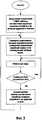
Алгоритм фиг.3 поясняет работу оператора ПЭВМ.The algorithm of figure 3 explains the operation of the PC operator.
Оператором на ПЭВМ создается таблица соответствия всех серийных номеров устройств с их сетевыми адресами от 1 до N, после чего она начинает инициализацию устройств в сети. Последовательно по списку ПЭВМ передает управляющую команду инициализации, содержащую: широковещательный адрес, команду инициализации, серийный номер опрашиваемого устройства и его сетевой адрес. Далее система переходит в рабочий режим, периодически анализируя признак изменения состава системы (отсутствие ответа на запрос, отключение устройства от сети, введение нового устройства в систему). При обнаружении изменения состава системы оператор ПЭВМ производит корректировку таблицы соответствия и переходит к повторной инициализации устройств в сети.The PC operator creates a table of correspondence of all serial numbers of devices with their network addresses from 1 to N, after which it starts the initialization of devices in the network. Sequentially from the list, the PC transmits the initialization control command, which contains: the broadcast address, the initialization command, the serial number of the device being polled and its network address. Then the system goes into working mode, periodically analyzing a sign of changes in the composition of the system (lack of response to a request, disconnecting the device from the network, introducing a new device into the system). If a change in the composition of the system is detected, the PC operator adjusts the correspondence table and proceeds to reinitialize the devices in the network.
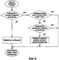
Алгоритм фиг.4 поясняет принцип работы устройства. Каждое принятое сообщение из сети анализируется на принадлежность данному устройству путем сравнения сетевого адреса устройства с сетевым адресом, содержащимся в сообщении. В случае определения его принадлежности данному устройству происходит обработка принятого сообщения и подготовка к приему нового сообщения. В противном случае происходит анализ сообщения на обращение ко всем устройствам в сети по серийному номеру, сравнение соответствующей части сообщения с серийным номером устройства и при положительном исходе выполняется процедура переписи полученного адреса в регистр сетевого адреса устройства.The algorithm of figure 4 explains the principle of operation of the device. Each received message from the network is analyzed for belonging to this device by comparing the network address of the device with the network address contained in the message. In the case of determining its belonging to this device, the processing of the received message and preparation for receiving a new message takes place. Otherwise, the message is analyzed for access to all devices in the network by the serial number, the corresponding part of the message is compared with the serial number of the device, and if the result is positive, the procedure of transferring the received address to the network address register of the device is performed.
Claims (1)
Translated fromRussianPriority Applications (1)
| Application Number | Priority Date | Filing Date | Title |
|---|---|---|---|
| RU2006122629/09ARU2372727C2 (en) | 2006-06-23 | 2006-06-23 | Initialisation device |
Applications Claiming Priority (1)
| Application Number | Priority Date | Filing Date | Title |
|---|---|---|---|
| RU2006122629/09ARU2372727C2 (en) | 2006-06-23 | 2006-06-23 | Initialisation device |
Publications (2)
| Publication Number | Publication Date |
|---|---|
| RU2006122629A RU2006122629A (en) | 2008-01-20 |
| RU2372727C2true RU2372727C2 (en) | 2009-11-10 |
Family
ID=39107900
Family Applications (1)
| Application Number | Title | Priority Date | Filing Date |
|---|---|---|---|
| RU2006122629/09ARU2372727C2 (en) | 2006-06-23 | 2006-06-23 | Initialisation device |
Country Status (1)
| Country | Link |
|---|---|
| RU (1) | RU2372727C2 (en) |
Cited By (2)
| Publication number | Priority date | Publication date | Assignee | Title |
|---|---|---|---|---|
| RU2601194C2 (en)* | 2012-02-27 | 2016-10-27 | Телевик Рэйл Нв | Devices and method for assigning network addresses |
| RU2840794C1 (en)* | 2024-11-26 | 2025-05-28 | федеральное государственное бюджетное образовательное учреждение высшего образования "Ульяновский государственный технический университет" | Antenna beam pattern control device |
Citations (6)
| Publication number | Priority date | Publication date | Assignee | Title |
|---|---|---|---|---|
| US5297191A (en)* | 1990-09-28 | 1994-03-22 | At&T Bell Laboratories | Method and apparatus for remotely programming a wireless telephone set |
| WO1995023487A1 (en)* | 1994-02-24 | 1995-08-31 | Gte Mobile Communications Service Corporation | Cellular radiotelephone system with remotely programmed mobile stations |
| RU2169437C1 (en)* | 1998-12-29 | 2001-06-20 | Свисском Мобиле Аг | Procedure to gain access to objects for users of telecommunication network |
| EP0940946B1 (en)* | 1998-03-06 | 2004-11-24 | Nec Corporation | IEEE-1394 serial bus network capable of multicast communication |
| RU2005109942A (en)* | 2002-09-06 | 2005-09-10 | Леново(Бейцзин) Лимитед (Cn) | METHOD FOR AUTOMATIC SEARCH FOR A DEVICE ON THE NETWORK |
| RU2269873C2 (en)* | 2000-09-13 | 2006-02-10 | Вп Медиа Инк | Wireless initialization device |
- 2006
- 2006-06-23RURU2006122629/09Apatent/RU2372727C2/enactive
Patent Citations (6)
| Publication number | Priority date | Publication date | Assignee | Title |
|---|---|---|---|---|
| US5297191A (en)* | 1990-09-28 | 1994-03-22 | At&T Bell Laboratories | Method and apparatus for remotely programming a wireless telephone set |
| WO1995023487A1 (en)* | 1994-02-24 | 1995-08-31 | Gte Mobile Communications Service Corporation | Cellular radiotelephone system with remotely programmed mobile stations |
| EP0940946B1 (en)* | 1998-03-06 | 2004-11-24 | Nec Corporation | IEEE-1394 serial bus network capable of multicast communication |
| RU2169437C1 (en)* | 1998-12-29 | 2001-06-20 | Свисском Мобиле Аг | Procedure to gain access to objects for users of telecommunication network |
| RU2269873C2 (en)* | 2000-09-13 | 2006-02-10 | Вп Медиа Инк | Wireless initialization device |
| RU2005109942A (en)* | 2002-09-06 | 2005-09-10 | Леново(Бейцзин) Лимитед (Cn) | METHOD FOR AUTOMATIC SEARCH FOR A DEVICE ON THE NETWORK |
Cited By (2)
| Publication number | Priority date | Publication date | Assignee | Title |
|---|---|---|---|---|
| RU2601194C2 (en)* | 2012-02-27 | 2016-10-27 | Телевик Рэйл Нв | Devices and method for assigning network addresses |
| RU2840794C1 (en)* | 2024-11-26 | 2025-05-28 | федеральное государственное бюджетное образовательное учреждение высшего образования "Ульяновский государственный технический университет" | Antenna beam pattern control device |
Also Published As
| Publication number | Publication date |
|---|---|
| RU2006122629A (en) | 2008-01-20 |
Similar Documents
| Publication | Publication Date | Title |
|---|---|---|
| US11080404B2 (en) | Firmware upgrade method, slave station of robot, and machine readable storage medium | |
| US8776080B2 (en) | Management component transport protocol interconnect filtering and routing | |
| US20080115144A1 (en) | Method and Apparatus for Web Based Storage on Demand | |
| US20040015957A1 (en) | Method to map an inventory management system to a configuration management system | |
| CN101447923B (en) | Duplicate internet protocol address resolution in a fragmented switch stack environment | |
| CN104954506A (en) | Account number management method and system as well as terminal devices | |
| CN104812021A (en) | Method and device for accessing AC (access controller) by AP (access point) | |
| US20060155838A1 (en) | Program installation system and method using the same | |
| CN118748640B (en) | A management communication method, device, equipment and medium | |
| US8819200B2 (en) | Automated cluster node configuration | |
| CN101002427A (en) | Method and system for dynamic device address management | |
| RU2372727C2 (en) | Initialisation device | |
| CN114629744B (en) | Data access method, system and related device based on macvlan host network | |
| KR100791293B1 (en) | Apparatus and method for data management of computer systems in a network | |
| CN105827496A (en) | Method and apparatus for managing PE device | |
| CN105677589A (en) | Access control method, access control device and access control system | |
| EP2044526A1 (en) | System and method for managing domain-state information | |
| CN103297548A (en) | Method and device for updating domain name resolution rules in cloud computing environment | |
| JP3730545B2 (en) | Service control application execution method and system | |
| US7702793B2 (en) | Method and apparatus for setting network using DHCP server or client function | |
| KR970056252A (en) | Distributed Object Access Information Management System and Its Decentralization Method | |
| CN114430392A (en) | Method and terminal for connecting Intel network card with Switch to expand internet access | |
| CN100459521C (en) | System and method for determining a designated connection between components of computing devices | |
| CN102025726A (en) | Home data network system centering on digital television | |
| US11895200B2 (en) | Access to an operator panel over an out-of-band local network domain |
Legal Events
| Date | Code | Title | Description |
|---|---|---|---|
| PD4A | Correction of name of patent owner |