RU2372705C1 - Dc electric motor with torque amplifier - Google Patents
Dc electric motor with torque amplifierDownload PDFInfo
- Publication number
- RU2372705C1 RU2372705C1RU2008146834/09ARU2008146834ARU2372705C1RU 2372705 C1RU2372705 C1RU 2372705C1RU 2008146834/09 ARU2008146834/09 ARU 2008146834/09ARU 2008146834 ARU2008146834 ARU 2008146834ARU 2372705 C1RU2372705 C1RU 2372705C1
- Authority
- RU
- Russia
- Prior art keywords
- magnets
- disk
- fixed
- movable
- disks
- Prior art date
Links
Images


Landscapes
- Dynamo-Electric Clutches, Dynamo-Electric Brakes (AREA)
Abstract
Description
Translated fromRussianНастоящее изобретение относится к области электротехники и может найти применение в качестве электродвигателя постоянного тока.The present invention relates to the field of electrical engineering and may find application as a direct current electric motor.
Известен электродвигатель трехфазного переменного тока АОМ-32-4, содержащий корпус статора с обмотками возбуждения, два подшипниковых щита, короткозамкнутый ротор, клеммовую коробку, наружный вентилятор.Known electric motor of three-phase alternating current AOM-32-4, containing a stator housing with field windings, two bearing shields, squirrel-cage rotor, terminal box, outdoor fan.
/М.М.Авдеев и др. Электропоезда переменного тока. М.: Транспорт, 1973, с.139-140, рис.96/./ M.M. Avdeev et al. AC electric trains. M .: Transport, 1973, p.139-140, Fig. 96 /.
Недостатками известного трехфазного переменного тока электродвигателя АОМ-32-4 являются: большой расход электроэнергии, невозможность перемены направления вращения вала, повышенный расход цветных и черных металлов, большие тепловые потери.The disadvantages of the known three-phase alternating current motor AOM-32-4 are: high power consumption, the inability to change the direction of rotation of the shaft, increased consumption of non-ferrous and ferrous metals, large heat loss.
Указанные недостатки обусловлены конструкцией электродвигателя.These disadvantages are due to the design of the electric motor.
Известен также электродвигатель постоянного тока с редуктором MЭ-241, содержащий корпус, закрытый передней и задней крышками, вал, свободный конец которого пропущен в отверстие передней крышки, выполненный заодно с якорем и коллектором, магнитные полюсы возбуждения, угольные щетки с держателем, клеммовую коробку, клеммы которой электрически соединены с угольными щетками, корпус редуктора, соединенный с корпусом электродвигателя закрытый крышками, ведомый вал, свободным конец которого пропущен в отверстие передней крышки и кинематически связан с валом электродвигателя.Also known is a direct current electric motor with gearbox ME-241, comprising a housing closed by front and rear covers, a shaft, the free end of which is passed into the hole of the front cover, made integral with the armature and collector, magnetic field poles, carbon brushes with holder, terminal box, the terminals of which are electrically connected to the carbon brushes, the gear housing connected to the motor housing closed by covers, the driven shaft, the free end of which is passed into the hole of the front cover and kinematically connected to the motor shaft.
/В.А.Вершигора, А.П.Игнатов, Н.В.Пятков. Автомобиль BAЗ-2121 "Нива", М.: Транспорт, 1980, с.234-235, рис.174/./ V.A. Vershigora, A.P. Ignatov, N.V. Pyatkov. Car BAZ-2121 "Niva", M .: Transport, 1980, p. 234-235, Fig. 174 /.
Известный электродвигатель постоянного тока с редуктором МЭ-241, как наиболее близкий по технической сущности и достигаемому полезному результату, принят за прототип.The well-known DC motor with gear ME-241, as the closest in technical essence and achieved useful result, adopted as a prototype.
Недостатками известного электродвигателя постоянного тока с редуктором MD-241, принятого за прототип, являются: большой расход электроэнергии, малая мощность, недостаточный крутящий момент, обгорание и окисление пластин коллектора.The disadvantages of the known DC motor with gearbox MD-241, adopted as a prototype, are: high power consumption, low power, insufficient torque, burning and oxidation of the collector plates.
Указанные недостатки обусловлены конструкцией электродвигателя.These disadvantages are due to the design of the electric motor.
Целью настоящего изобретения является повышение технических характеристик электродвигателя постоянного тока с редуктором.The aim of the present invention is to improve the technical characteristics of a DC motor with gear.
Указанная цель согласно изобретению обеспечивается тем, что на ведомом валу редуктора дополнительно закреплены: маховик с зубчатым венцом, который через промежуточную шестерню соединен с шестерней вала электродвигателя, передний и задний подвижные диски с постоянными магнитами, размещенными соответственно на задней и передней торцевых поверхностях в глухих радиальных пазах и обращенными одними и теми же полюсами на заднюю торцевую поверхность переднего подвижного диска и противоположными полюсами на переднюю торцевую поверхность заднего подвижного диска, причем продольная ось каждого из магнитов переднего подвижного диска наклонена в сторону передней крышки корпуса редуктора и установлена под углом к его задней торцевой поверхности, а продольная ось каждого из магнитов заднего подвижного диска также наклонена в сторону передней крышки корпуса редуктора и установлена под таким же углом к его передней торцевой поверхности, кроме того, неподвижный диск, установленный с возможностью продольного перемещения по направляющим и фиксации посредством механизма, не показанного на чертежах, кинематически связанного с ручкой переключения, установленной снаружи на корпусе редуктора, имеющий сквозные радиальные пазы, в которых закреплены постоянные магниты, концы которых выходят на переднюю и заднюю торцевые поверхности и обращены к переднему и заднему подвижным дискам ведомого вала своими одноименными полюсами, причем продольная ось каждого из магнитов наклонена в сторону передней крышки корпуса редуктора и установлена под таким же углом к передней и задней торцевым поверхностям, причем подвижные и неподвижный диски выполнены из немагнитного материала, а при смещении неподвижного диска в сторону переднего или заднего подвижных дисков и совмещении магнитов продольные оси магнитов неподвижного диска соосны всем продольным осям магнитов переднего или заднего подвижных дисков, а количество магнитов на всех трех дисках должно быть одинаково, кроме того, между неподвижным диском и передним подвижным диском закреплен неподвижный защитный диск, выполненный из ферросплава с радиальными сквозными пазами, продольные оси которых наклонены в сторону передней крышки корпуса редуктора под таким же углом и соосны продольным осям магнитов переднего подвижного диска при их совмещении, кроме того, между неподвижным диском и задним подвижным диском закреплен неподвижный защитный диск, выполненный из ферросплава о радиальными сквозными пазами, продольные оси которых наклонены в сторону передней крышки корпуса редуктора под таким же углом и соосны продольным осям магнитов заднего подвижного диска при их совмещении.The specified purpose according to the invention is ensured by the fact that on the driven shaft of the gearbox are additionally fixed: a flywheel with a gear ring, which is connected via an intermediate gear to the gear shaft of the electric motor, front and rear movable disks with permanent magnets located respectively on the rear and front end surfaces in blind radial grooves and facing the same poles to the rear end surface of the front movable disk and opposite poles to the front end surface of the bottom of the movable disk, and the longitudinal axis of each of the magnets of the front movable disk is tilted towards the front cover of the gear housing and installed at an angle to its rear end surface, and the longitudinal axis of each of the magnets of the rear movable disk is also tilted towards the front of the gear housing and mounted under the same angle to its front end surface, in addition, a fixed disk mounted with the possibility of longitudinal movement along the rails and fixing by means of a mechanism, not yet shown in the drawings, kinematically connected with a shift knob mounted externally on the gear housing, having through radial grooves in which permanent magnets are fixed, the ends of which extend to the front and rear end surfaces and face the front and rear movable drives of the driven shaft with their same poles, moreover, the longitudinal axis of each of the magnets is tilted towards the front cover of the gearbox housing and is installed at the same angle to the front and rear end surfaces, while movable and not the sliding disks are made of non-magnetic material, and when the fixed disk is displaced towards the front or rear movable disks and the magnets are aligned, the longitudinal axes of the magnets of the fixed disk are aligned with all the longitudinal axes of the magnets of the front or rear movable disks, and the number of magnets on all three disks should be the same, except Moreover, between the fixed disk and the front movable disk, a fixed protective disk is made of ferroalloy with radial through grooves, the longitudinal axes of which are inclined in side of the front cover of the gearbox housing at the same angle and are aligned with the longitudinal axes of the magnets of the front movable disk when they are combined, in addition, between the fixed disk and the rear movable disk there is a fixed protective disk made of ferroalloy with radial through grooves whose longitudinal axes are inclined to the side the front cover of the gearbox housing at the same angle and are aligned with the longitudinal axes of the magnets of the rear movable disk when they are combined.
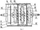
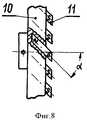
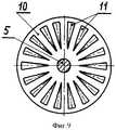
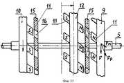
Сущность изобретения поясняется чертежами, где на фигуре 1 изображен общий вид электродвигателя постоянного тока с редуктором, на фигуре 2 - схема размещения узлов в корпусе редуктора, на фигуре 3 - устройство усилителя крутящего момента, на фигуре 4 - вид на заднюю торцевую поверхность переднего подвижного диска, на фигуре 5 - вид на переднюю торцевую поверхность переднего подвижного диска, на фигуре 6 - вид на боковую поверхность переднего подвижного диска, на фигуре 7 - вид на заднюю торцевую поверхность заднего подвижного диска, на фигуре 8 - вид сбоку на задний подвижный диск, на фигуре 9 - вид на переднюю торцевую поверхность заднего подвижного диска, на фигуре 10 - вид на торцевую поверхность защитного диска, на фигуре 11 - вид сбоку на защитный диск, на фигуре 12 - вид на торцевую поверхность неподвижного диска, на фигуре 13 - вид сбоку на неподвижный диск с частичным разрезом, на фигуре 14 - общий вид магнита подвижных и неподвижного дисков, на фигуре 15 - схема усиления крутящего момента при прямом вращении ведомого вала, на фигуре 16 - схема усиления крутящего момента при обратном вращении ведомого вала.The invention is illustrated by drawings, where figure 1 shows a General view of a DC motor with gear, figure 2 is a diagram of the nodes in the gear housing, figure 3 is a torque amplifier device, figure 4 is a view of the rear end surface of the front movable disk , in figure 5 is a view of the front end surface of the front movable disk, in figure 6 is a view of the side surface of the front movable disk, in figure 7 is a view of the rear end surface of the rear movable disk, in figure 8 - id on the side of the rear movable disk, in figure 9 - view of the front end surface of the rear movable disk, in figure 10 - view of the end surface of the protective disk, in figure 11 - side view of the protective disk, in figure 12 - view of the end surface of the stationary disk, in figure 13 is a side view of a stationary disk with a partial section, in figure 14 is a General view of the magnet of the movable and fixed disks, in figure 15 is a diagram of the torque amplification with direct rotation of the driven shaft, in figure 16 is a diagram of the torque amplification for reverse rotated and the driven shaft.
Электродвигатель постоянного тока с усилителем крутящего момента 1 содержит корпус, закрытий передней и задней крышками, внутри которого установлены магнитные полюсы возбуждения, вал, установленный в подшипниках крышек, свободный конец которого пропущен в отверстие передней крышки, выполненный заодно с якорем и коллектором, который контактирует с угольными щетками, установленными на держателе, выводы от которых выведены в клеммовую коробку. Корпус 2 усилителя крутящего момента соединен болтами с корпусом электродвигателя постоянного тока. Корпус цилиндрической формы закрыт передней 3 и задней 4 крышками, внутри которого в подшипниках крышек установлен ведомый вал 5, свободный конец которого пропущен в отверстие передней крышки. На ведомом валу закреплены: маховик 6 с зубчатым венцом, который через промежуточную шестерню 7 соединен с шестерней 8, закрепленной на валу электродвигателя постоянного тока, передний 9 и задний 10 подвижные диски с постоянными магнитами 11, размещенными соответственно на задней и передней торцевых поверхностях в глухих радиальных пазах и обращенными одними и теми же полюсами на заднюю торцевую поверхность переднего подвижного диска и противоположными полюсами на переднюю торцевую поверхность заднего подвижного диска. Продольная ось каждого из магнитов переднего подвижного диска установлена под углом α, равным 45°, к его задней торцевой поверхности, а продольная ось каждого из магнитов заднего подвижного диска установлена под таким же углом к его передней торцевой поверхности. Неподвижный диск 12, установленный с возможностью продольного перемещения по направляющим 13, привернутым болтами к корпусу, посредством механизма, не показанного на чертежах, кинематически связан с ручкой переключения 14, установленной снаружи на корпусе усилителя крутящего момента. Неподвижный диск имеет сквозные радиальные пазы, в которые вставлены постоянные магниты, концы которых выходят на переднюю и заднюю торцевые поверхности и обращены к переднему и заднему подвижным дискам ведомого вала своими одноименными полюсами. Продольная ось каждого магнита установлена под таким же углом к торцевым поверхностям неподвижного диска, что и упомянутые ранее магниты. При смещении неподвижного диска в сторону переднего или заднего подвижных дисков и совмещении магнитов неподвижного диска с магнитами переднего или заднего подвижных дисков оси всех магнитов соосны друг другу (фиг.15, 16), а количество магнитов на всех трех дисков должно быть одинаковым. Все магниты должны обладать высоким уровнем напряженности магнитного поля, и они должны быть изготовлены из ферромагнитного порошка с добавками редкоземельных элементов. Между неподвижным диском и передним подвижным диском, между неподвижным диском и задним подвижным диском закреплены неподвижные защитные диски 15, одинаковые по конструкции, выполненные из ферросплава, имеющие радиальные сквозные пазы 16. Продольные оси каждого паза установлены под углом α, равным 45°, к задней торцевой поверхности.A direct current electric motor with a
Работа электродвигателя постоянного тока с усилителем крутящего момента.The operation of a DC motor with a torque amplifier.
Электродвигатель постоянного тока 1 может работать в нескольких режимах. При подключении к сети электродвигателя ручка переключения 14 находится в среднем положении (фиг.1), неподвижный диск 12 с магнитами 11 также находится в среднем положении. Вал электродвигателя вращается и через шестерни 7, 8, зубчатый венец маховика 6 вращает ведомый вал 5. При этом маховик 6 за счет инерции запасает энергию вращения и делает его равномерным. В этом случае никакого усиления крутящего момента не происходит. Если электродвигатель подключен к сети таким образом, что ведомый вал 5 вращается по часовой стрелке и необходимо увеличить крутящий момент, то ручка управления 14 поворачивается вправо. Неподвижный диск 12 с магнитами 11 механизмом, не показанным на чертеже, передвигается вдоль по направляющим 13 в сторону переднего подвижного диска 9 (на фигуре 15 показано горизонтальной стрелкой) и фиксируется на некотором расстоянии от неподвижного защитного диска 15. В этом случае к силе F, с которой вращается передний подвижный диск 9, добавляется сила Fм, которая возникает при отталкивании магнитов 11 переднего подвижного диска 9 от одноименных полюсов магнитов 11 неподвижного диска 12. Это происходит, когда магниты неподвижного диска 12 и магниты переднего подвижного диска 9, а также пазы 16 неподвижного защитного диска 15 находятся на одной линии, как показано на фигуре 15. Сила отталкивания Fм и сила F, с которой вращается передний подвижный диск 9, действующие под углом друг к другу, образуют равнодействующую силу Fр, которая является результирующей силой, действующей на передний подвижный диск 9, и которая больше силы F. Следовательно, происходит увеличение крутящего момента на переднем подвижном диске 9 и соответственно на ведомом валу 5. В то время, когда магнитное поле магнитов переднего подвижного диска 9 и неподвижного диска 12 направлено вдоль ведомого вала и может тормозить ведомый вал, неподвижный защитный диск 15 не дает возможности взаимодействовать магнитам обоих дисков, экранируя их. Маховик 6 помогает выводить диски из этого положения. Таким образом при вращении переднего подвижного диска 9 из-за одновременного периодического отталкивания его магнитов от магнитов неподвижного диска 12 происходит увеличение крутящего момента. При переключении электродвигателя 1 на обратный ход ведомый вал 5 начинает вращаться в противоположную сторону против часовой стрелки. Ручка переключателя 14 передвигается влево и фиксируется (На фигуре 16 показано горизонтальной стрелкой). Неподвижный диск 12 передвигается в сторону заднего подвижного диска 10 и магниты обоих дисков начинают взаимодействовать друг с другом, как было описано выше. При этом также происходит увеличение крутящего момента. Таким образом за счет энергии постоянных магнитов можно получить более высокую мощность на ведомом валу при меньшей затратной мощности на ведущем валу.The
Предлагаемый электродвигатель может быть использован там, где необходима экономия электроэнергии. Например, на электромобилях.The proposed electric motor can be used where energy savings are needed. For example, on electric vehicles.
Положительный эффект: экономия электроэнергии, посредством маломощного электродвигателя можно приводить в движение механизмы, требующие большой мощности.Positive effect: energy saving, by means of a low-power electric motor, mechanisms requiring high power can be set in motion.
Claims (1)
Translated fromRussianPriority Applications (1)
| Application Number | Priority Date | Filing Date | Title |
|---|---|---|---|
| RU2008146834/09ARU2372705C1 (en) | 2008-11-26 | 2008-11-26 | Dc electric motor with torque amplifier |
Applications Claiming Priority (1)
| Application Number | Priority Date | Filing Date | Title |
|---|---|---|---|
| RU2008146834/09ARU2372705C1 (en) | 2008-11-26 | 2008-11-26 | Dc electric motor with torque amplifier |
Publications (1)
| Publication Number | Publication Date |
|---|---|
| RU2372705C1true RU2372705C1 (en) | 2009-11-10 |
Family
ID=41354854
Family Applications (1)
| Application Number | Title | Priority Date | Filing Date |
|---|---|---|---|
| RU2008146834/09ARU2372705C1 (en) | 2008-11-26 | 2008-11-26 | Dc electric motor with torque amplifier |
Country Status (1)
| Country | Link |
|---|---|
| RU (1) | RU2372705C1 (en) |
Citations (7)
| Publication number | Priority date | Publication date | Assignee | Title |
|---|---|---|---|---|
| US1340248A (en)* | 1919-08-30 | 1920-05-18 | Arthur G Petit | Knockdown box |
| WO1997009191A1 (en)* | 1995-09-04 | 1997-03-13 | Asea Brown Boveri Ab | Hybrid drive system |
| CN1196601A (en)* | 1998-04-16 | 1998-10-21 | 卜中山 | Brushless direct current motor with axial magnetic circuit |
| RU2158465C1 (en)* | 1999-07-09 | 2000-10-27 | Григорчук Владимир Степанович | Direct-current motor |
| RU2196379C2 (en)* | 2001-02-07 | 2003-01-10 | Григорчук Владимир Степанович | Gas-tube dc motor |
| RU2206171C2 (en)* | 2001-06-05 | 2003-06-10 | Григорчук Владимир Степанович | Direct-current motor |
| RU2239934C1 (en)* | 2003-03-03 | 2004-11-10 | Григорчук Владимир Степанович | Direct-current motor |
- 2008
- 2008-11-26RURU2008146834/09Apatent/RU2372705C1/ennot_activeIP Right Cessation
Patent Citations (7)
| Publication number | Priority date | Publication date | Assignee | Title |
|---|---|---|---|---|
| US1340248A (en)* | 1919-08-30 | 1920-05-18 | Arthur G Petit | Knockdown box |
| WO1997009191A1 (en)* | 1995-09-04 | 1997-03-13 | Asea Brown Boveri Ab | Hybrid drive system |
| CN1196601A (en)* | 1998-04-16 | 1998-10-21 | 卜中山 | Brushless direct current motor with axial magnetic circuit |
| RU2158465C1 (en)* | 1999-07-09 | 2000-10-27 | Григорчук Владимир Степанович | Direct-current motor |
| RU2196379C2 (en)* | 2001-02-07 | 2003-01-10 | Григорчук Владимир Степанович | Gas-tube dc motor |
| RU2206171C2 (en)* | 2001-06-05 | 2003-06-10 | Григорчук Владимир Степанович | Direct-current motor |
| RU2239934C1 (en)* | 2003-03-03 | 2004-11-10 | Григорчук Владимир Степанович | Direct-current motor |
Non-Patent Citations (2)
| Title |
|---|
| АВДЕЕВ М.М. и др. Электропоезда переменного тока. - М.: Транспорт, 1973, с.139-140, рис.96.* |
| ВЕРШИГОРА В.А., ИГНАТОВ А.П., ПЯТКОВ Н.В. Автомобиль ВАЗ-2121 «Нива». - М.: Транспорт, 1980, с.234-235, рис.174.* |
Similar Documents
| Publication | Publication Date | Title |
|---|---|---|
| US4751486A (en) | Magnetic rotation apparatus | |
| Atallah et al. | A novel “pseudo” direct-drive brushless permanent magnet machine | |
| BG61589B1 (en) | Rotary magnetic device | |
| EP1100188A3 (en) | Electric machine with permanent magnet poles and controllable rotor flux | |
| Atallah et al. | A new PM machine topology for low-speed, high-torque drives | |
| CN106953493B (en) | Brushless alternating current oscillation micro motor | |
| RU2372705C1 (en) | Dc electric motor with torque amplifier | |
| CN101621224B (en) | Coaxial inner and outer coil motor | |
| TW201810863A (en) | Nested stator structure for DC motor | |
| RU2206170C2 (en) | Linear permanent-magnet generator | |
| RU2668817C1 (en) | Synchronous motor with magnetic reduction | |
| CN110924785A (en) | Single-side magnetic suspension unloading linear driving translation door | |
| CN101447362A (en) | Permanent magnet swing angle electric operating mechanism of high voltage circuit breaker | |
| CN214380579U (en) | Rotating mechanism | |
| RU2001118970A (en) | Permanent Magnet Linear Motor | |
| JP2000515093A (en) | Axle hub mounted energy converter | |
| RajaRajeswari et al. | Zero point energy conversion for self-sustained generation | |
| KR100758670B1 (en) | Magnetic amplification engine | |
| RU2417505C1 (en) | Electric motor of mining mill of direct drive system | |
| CN116334886B (en) | Washing machine and control method thereof | |
| CN220915141U (en) | Arc-shaped linear motor | |
| CN223379052U (en) | Magnetic drive power generation device | |
| CN114510147B (en) | Force feedback device and electronic equipment | |
| RU2103790C1 (en) | Reciprocating engine | |
| KR102685213B1 (en) | Double repulsive Device using Metal Magnet Interaction Phenomenon of the Magnet |
Legal Events
| Date | Code | Title | Description |
|---|---|---|---|
| MM4A | The patent is invalid due to non-payment of fees | Effective date:20131127 |