RU2370243C2 - Method of fastening tension threads to prosthetic ligament - Google Patents
Method of fastening tension threads to prosthetic ligamentDownload PDFInfo
- Publication number
- RU2370243C2 RU2370243C2RU2006131415/14ARU2006131415ARU2370243C2RU 2370243 C2RU2370243 C2RU 2370243C2RU 2006131415/14 ARU2006131415/14 ARU 2006131415/14ARU 2006131415 ARU2006131415 ARU 2006131415ARU 2370243 C2RU2370243 C2RU 2370243C2
- Authority
- RU
- Russia
- Prior art keywords
- ligament
- thread
- ligature
- loop
- tension
- Prior art date
Links
- 210000003041ligamentAnatomy0.000titleclaimsabstractdescription75
- 238000000034methodMethods0.000titleclaimsabstractdescription15
- 238000004804windingMethods0.000claimsabstractdescription8
- 238000004519manufacturing processMethods0.000claimsabstractdescription5
- 239000000463materialSubstances0.000claimsdescription9
- 238000009434installationMethods0.000claimsdescription8
- 230000015572biosynthetic processEffects0.000claimsdescription4
- 210000001306articular ligamentAnatomy0.000claimsdescription3
- 229920002994synthetic fiberPolymers0.000claimsdescription3
- 239000012209synthetic fiberSubstances0.000claimsdescription3
- 229920005594polymer fiberPolymers0.000claimsdescription2
- 210000000988bone and boneAnatomy0.000abstractdescription8
- 229920001059synthetic polymerPolymers0.000abstractdescription4
- 230000000399orthopedic effectEffects0.000abstractdescription2
- 239000003814drugSubstances0.000abstract1
- 230000000694effectsEffects0.000abstract1
- 239000000126substanceSubstances0.000abstract1
- 210000003414extremityAnatomy0.000description4
- 206010061218InflammationDiseases0.000description3
- 239000000835fiberSubstances0.000description3
- 230000004054inflammatory processEffects0.000description3
- 239000002245particleSubstances0.000description3
- -1polyethylene terephthalatePolymers0.000description3
- 229920000139polyethylene terephthalatePolymers0.000description3
- 239000005020polyethylene terephthalateSubstances0.000description3
- 239000004033plasticSubstances0.000description2
- 229920003023plasticPolymers0.000description2
- 239000011230binding agentSubstances0.000description1
- 230000005540biological transmissionEffects0.000description1
- 238000006073displacement reactionMethods0.000description1
- 230000002452interceptive effectEffects0.000description1
- 210000003127kneeAnatomy0.000description1
- 210000000629knee jointAnatomy0.000description1
- 239000002184metalSubstances0.000description1
- 238000000465mouldingMethods0.000description1
- 229920000642polymerPolymers0.000description1
- 229920001296polysiloxanePolymers0.000description1
- 230000001681protective effectEffects0.000description1
- 238000009958sewingMethods0.000description1
- 239000004753textileSubstances0.000description1
Images


Classifications
- A—HUMAN NECESSITIES
- A61—MEDICAL OR VETERINARY SCIENCE; HYGIENE
- A61F—FILTERS IMPLANTABLE INTO BLOOD VESSELS; PROSTHESES; DEVICES PROVIDING PATENCY TO, OR PREVENTING COLLAPSING OF, TUBULAR STRUCTURES OF THE BODY, e.g. STENTS; ORTHOPAEDIC, NURSING OR CONTRACEPTIVE DEVICES; FOMENTATION; TREATMENT OR PROTECTION OF EYES OR EARS; BANDAGES, DRESSINGS OR ABSORBENT PADS; FIRST-AID KITS
- A61F2/00—Filters implantable into blood vessels; Prostheses, i.e. artificial substitutes or replacements for parts of the body; Appliances for connecting them with the body; Devices providing patency to, or preventing collapsing of, tubular structures of the body, e.g. stents
- A61F2/02—Prostheses implantable into the body
- A61F2/08—Muscles; Tendons; Ligaments
Landscapes
- Health & Medical Sciences (AREA)
- Orthopedic Medicine & Surgery (AREA)
- Rehabilitation Therapy (AREA)
- Rheumatology (AREA)
- Cardiology (AREA)
- Oral & Maxillofacial Surgery (AREA)
- Transplantation (AREA)
- Engineering & Computer Science (AREA)
- Biomedical Technology (AREA)
- Heart & Thoracic Surgery (AREA)
- Vascular Medicine (AREA)
- Life Sciences & Earth Sciences (AREA)
- Animal Behavior & Ethology (AREA)
- General Health & Medical Sciences (AREA)
- Public Health (AREA)
- Veterinary Medicine (AREA)
- Prostheses (AREA)
- Surgical Instruments (AREA)
Abstract
Description
Translated fromRussianНастоящее изобретение относится к способу крепления натяжных нитей к оконечностям протезной связки для замены биологических суставных связок, в особенности связок колена, и к связке, изготовленной таким образом.The present invention relates to a method for attaching tension threads to the ends of a prosthetic ligament to replace biological articular ligaments, especially knee ligaments, and to a ligament made in this way.
В настоящее время искусственные связки изготавливают большей частью путем наматывания или накладывания друг на друга слоев сетки из синтетических полимерных волокон, как правило, из полиэтилентерефталата. Эти связки в целом имеют форму удлиненных цилиндров, включающих среднюю внутрисуставную часть между двумя концевыми внутрикостными частями. Примерами таких связок являются, в частности, связки, описанные в патентах FR 2.755.846 и FR 2.697.151.Currently, artificial ligaments are made mainly by winding or superimposing on each other layers of a mesh of synthetic polymer fibers, usually polyethylene terephthalate. These ligaments are generally in the form of elongated cylinders, including the middle intraarticular part between the two end intraosseous parts. Examples of such ligaments are, in particular, the ligaments described in patents FR 2.755.846 and FR 2.697.151.
Для упрощения пропускания этих связок через костные каналы и обеспечения их надежного крепления связки снабжены концевыми натяжными нитями. Эти натяжные нити крепятся к связкам путем выполнения на некотором расстоянии от их свободных концов петли с нитью, охватывающей связку по радиусу; два конца этой нити вводят в толщу связки, к которой прикреплена упомянутая нить после протягивания упомянутых двух концов в толще связки в направлении, в целом параллельном продольной оси связки, а затем выводят через свободный конец связки. Затем упомянутые два конца нити связывают между собой, располагая узел на уровне места выхода этих концов из связки.To simplify the transmission of these ligaments through the bone channels and ensure their reliable fastening, the ligaments are equipped with end tension threads. These tension yarns are attached to the bundles by performing at some distance from their free ends of the loop with a thread covering the bundle along the radius; the two ends of this thread are inserted into the thickness of the bundle to which the said thread is attached after pulling the two ends in the thickness of the bundle in a direction generally parallel to the longitudinal axis of the bundle, and then out through the free end of the bundle. Then the mentioned two ends of the thread are connected together, placing the node at the level of the place where these ends exit the bundle.
Для защиты свободных оконечностей связки, направления их протягивания через костные каналы и предотвращения смещения натяжных нитей при приложении к ним усилия натяжения производителями связок разработаны различные технические решения для наконечников. В настоящем описании термин "наконечник" означает любую деталь, охватывающую оконечности протезной связки, снабженные натяжными нитями.To protect the free ends of the ligament, the direction of their pulling through the bone channels and to prevent the displacement of the tension threads while applying tension to them, the manufacturers of the ligaments have developed various technical solutions for the tips. In the present description, the term "tip" means any part covering the extremities of the prosthetic ligament provided with tension threads.
Первое из таких решений состоит в зажимании связки ниже петли натяжной нити кольцом, обычно металлическим. Однако такие кольца часто застревают в костных каналах и их трудно провести через изогнутые каналы, вследствие чего установка таких связок является довольно трудоемкой и сложной операцией.The first of these solutions is to clamp the ligament below the loop of the tension thread by a ring, usually a metal one. However, such rings often get stuck in the bone canals and are difficult to pass through the curved channels, as a result of which the installation of such ligaments is quite time-consuming and difficult operation.
Второе решение состоит в том, что на оконечность связки надевают полиэтиленовый колпачок, в дне которого имеется отверстие для прохода концов натяжной нити. Упомянутые концы связывают между собой, располагая узел точно у места их выхода из колпачка, с целью фиксирования последнего и предотвращения скольжения нити. Хотя такие колпачки создают меньше осложнений, чем кольца, их применение остается затруднительным в некоторых обстоятельствах, например в случае протезирования перекрещивающихся задних связок коленного сустава. Кроме того, эти колпачки иногда применяют в сочетании с кольцами, что повышает вероятность воспалительных явлений вследствие различной природы двух применяемых материалов.The second solution is to put a plastic cap on the end of the bundle, in the bottom of which there is an opening for the passage of the ends of the tension thread. The aforementioned ends are connected together, positioning the knot exactly at the place of their exit from the cap, in order to fix the latter and prevent the thread from slipping. Although such caps create fewer complications than rings, their use remains difficult in some circumstances, for example, in the case of prosthetic intersecting posterior ligaments of the knee joint. In addition, these caps are sometimes used in combination with rings, which increases the likelihood of inflammation due to the different nature of the two materials used.
Третье решение, применяемое некоторыми производителями, состоит в использовании оболочек из пластичной полимерной (ПВХ) пленки, охватывающих оконечности связки и открытых в точке выхода концов натяжной нити. Такие оболочки можно изготовлять, например, путем горячего формования. Их недостаток заключается в значительной длине и относительно высокой жесткости, вследствие чего затрудняется прохождение связки через костные каналы.The third solution used by some manufacturers is the use of plastic polymer (PVC) film sheaths, covering the ends of the bundle and open at the exit point of the ends of the tension thread. Such casings can be made, for example, by hot molding. Their disadvantage lies in their considerable length and relatively high stiffness, which makes it difficult for the ligament to pass through the bone canals.
Наконец, еще одно решение предусматривает применение силиконовых направляющих, формуемых литьем вокруг натяжной нити и имеющих форму удлиненного конуса. Хотя эти направляющие имеют требуемую гибкость, они могут застревать в костных каналах, от них могут отделяться частицы материала, и направляющие могут застревать в каналах вследствие их значительной величины. Кроме того, отрывающиеся частицы могут вызвать воспалительную реакцию.Finally, another solution involves the use of silicone guides, molded around a tension thread and having the shape of an elongated cone. Although these guides have the required flexibility, they can get stuck in the bone channels, particles of material can separate from them, and the guides can get stuck in the channels due to their significant size. In addition, detached particles can cause an inflammatory reaction.
Настоящее изобретение предусматривает устранение этих затруднений, предлагая способ изготовления протезной связки, включающий стадию наматывания или накладывания друг на друга слоев сетки из синтетических полимерных волокон, за которой следуют стадия крепления к каждой из оконечностей связки натяжной нити, а затем стадия установки наконечников на упомянутые оконечности, отличающийся тем, что упомянутая стадия установки наконечников состоит в выполнении радиальной лигатуры связки, снабженной натяжными нитями, лигатурной нитью.The present invention provides a solution to these difficulties by proposing a method for manufacturing an orthopedic ligament, comprising the step of winding or superimposing on each other layers of a mesh of synthetic polymer fibers, followed by the step of attaching a tension thread to each of the ends of the ligament, and then the step of fitting the tips to said ends, characterized in that the said stage of the installation of the tips consists in performing a radial ligature of the ligament equipped with tension threads, ligature thread.
Выражение "лигатурная нить" в настоящем описании означает текстильную нить, которая по техническим характеристикам предназначена для выполнения перевязки (лигатуры) в обычных условиях.The expression "ligature yarn" in the present description means a textile yarn, which according to the technical characteristics is intended to perform ligation (ligature) under ordinary conditions.
Понятно, что такой наконечник, состоящий из лигатуры, является гибким и не создает никакой мешающей избыточной толщины на оконечности связки; таким образом, он устраняет затруднения при установке связки, а именно при введении ее в костные каналы и, в частности, при проведении через изгибы, какова бы ни была их конфигурация.It is clear that such a tip, consisting of a ligature, is flexible and does not create any interfering excess thickness at the end of the ligament; thus, it eliminates the difficulty in installing the ligament, namely when it is inserted into the bone canals and, in particular, when passing through the bends, whatever their configuration.
Кроме того, в соответствии с одной из существенных отличительных особенностей изобретения лигатурная нить выполнена из того же материала, что и синтетические волокна, из которых состоит сетка. Таким образом, вероятность воспалительной реакции в организме пациента значительно понижается, поскольку наконечник имеет ту же природу, что и материал, из которого состоит связка, и, кроме того, отрыв частиц материала происходит в весьма незначительной степени или вообще не имеет места. Кроме того, следует отметить известное экономическое преимущество применения одного и того же исходного материала.In addition, in accordance with one of the essential distinguishing features of the invention, the ligature thread is made of the same material as the synthetic fibers that make up the mesh. Thus, the likelihood of an inflammatory reaction in the patient's body is significantly reduced, since the tip has the same nature as the material of which the ligament consists, and, in addition, the detachment of particles of the material occurs to a very small extent or does not take place at all. In addition, it should be noted the well-known economic advantage of using the same source material.
Наконец, хорошо известна стойкость и целостность лигатур и других узлов при условии их правильного выполнения.Finally, the durability and integrity of ligatures and other nodes is well known, provided that they are correctly executed.
Другие преимущества и характеристики настоящего изобретения вытекают из приведенного ниже в качестве неограничительного примера описания последовательности стадий процесса крепления натяжных нитей к протезной связке после намотки или накладывания друг на друга слоев сетки из полимерных волокон со ссылками на прилагаемые чертежи, на которых:Other advantages and characteristics of the present invention result from the following, as a non-restrictive example, of the description of the sequence of stages of the process of attaching the tension threads to the prosthetic ligament after winding or overlapping layers of polymer fiber mesh with reference to the accompanying drawings, in which:
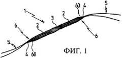
- на Фиг.1 схематически изображена в перспективе искусственная связка;- figure 1 is a schematic perspective view of an artificial ligament;
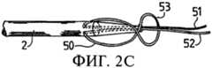
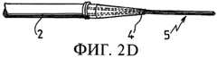
- на Фиг.2 изображена последовательность операций соединения натяжной нити с оконечностью связки согласно одному из вариантов осуществления настоящего изобретения;- figure 2 shows the sequence of operations connecting the tension thread with the end of the bundle according to one of the embodiments of the present invention;
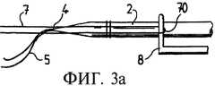
- на Фиг.3 изображена последовательность одного из вариантов выполнения лигатуры, образующей гибкий наконечник по настоящему изобретению.- figure 3 shows the sequence of one of the embodiments of the ligature, forming a flexible tip of the present invention.
Как видно из Фиг.1, искусственная связка 1 в целом имеет форму удлиненного цилиндра, который содержит между двумя внутрикостными концевыми частями 2 среднюю внутрисуставную часть 3. На каждой из оконечностей 4 связка снабжена натяжными нитями 5, причем каждая оконечность имеет наконечник 6, который в данном случае представляет собой лигатуру 60, выполненную по способу, подробно описанному ниже. Эти искусственные связки изготовлены путем наматывания или накладывания друг на друга слоев сетки из синтетических полимерных волокон, выполненных обычно из полиэтилентерефталата. Эта сетка обрезана и профилирована с расчетом на формирование желаемой формы оконечностей 4 связки 1, а затем смотана. Примеры связок этого типа и подробности способов их изготовления можно найти, например, в патентах FR 2.755.846 или FR 2.697.151. Наконец, форму, приданную таким образом связке 1, фиксируют путем продольной сшивки связки.As can be seen from Figure 1, the artificial ligament 1 as a whole has the shape of an elongated cylinder, which contains between the two
Затем следует установка натяжных нитей 5, необходимых для монтажа связки в организме пациента, с целью обеспечения хирургу возможности проведения связки через костные каналы, а также точной ее установки на место и придания ей натяжения, необходимого для протезирования.Then follows the installation of the
Как видно из Фиг.2, а также в соответствии с одним из аспектов настоящего изобретения, установку натяжной нити 5 на оконечности связки выполняют согласно последовательности этапов, показанных на Фиг.2A-2D. Первый этап упомянутой последовательности состоит в подготовке натяжной нити 5 с последующим формированием петли 50 вокруг тела связки 1 без перекрещивания концов нити вокруг связки и с расположением упомянутой петли 50 на некотором расстоянии от оконечности 4 связки 1. Это расстояние обычно лежит в пределах от 20 мм до 50 мм от оконечности, в зависимости от типа изготовляемой связки. Например, в случае связки, имеющей оконечности конической формы, это расстояние составляет обычно от 30 мм до 40 мм.As can be seen from Figure 2, and in accordance with one aspect of the present invention, the installation of the
Затем берут два свободных конца 51, 52 натяжной нити и вводят их с диаметрально противоположных сторон петли 50 в толщу связки 1. Затем их проталкивают в сторону соответствующей оконечности 4 в направлении вдоль связки и выводят наружу со стороны оконечности. На этом этапе следует действовать так, чтобы величина петли 50 не уменьшалась.Then take two
Далее, как показано на Фиг.2В, перекручивают петлю 50 таким образом, чтобы образовалась фигура, подобная цифре 8, основание которой закреплено в связке и которая образует вторую петлю 53, соответствующую верхней (меньшей) части восьмерки. Затем вводят оконечность 4 связки со свободными концами 51, 52 натяжной нити в упомянутую вторую петлю 53 и подтягивают упомянутые первую и вторую петли, соединенные между собой в виде восьмерки, так, чтобы они сдвинулись в место ввода обоих свободных концов натяжной нити в связку. Наконец, затягивают полученный таким образом узел путем натягивания свободных концов 51, 52 натяжной нити 5.Further, as shown in FIG. 2B,
Согласно факультативному и предпочтительному варианту затем у оконечности 4 связки выполняют концевой фиксирующий шов на уровне сечения связки, в котором оба конца 51, 52 натяжной нити входят в толщу связки. Этот фиксирующий шов предназначен для предотвращения скольжения натяжной нити 5 при воздействии на нее значительного усилия натяжения, в частности, при креплении стяжки. Фиксирующий шов выполняют, например, с помощью швейной машины, снабженной программой выполнения фиксирующего шва. Возможно, разумеется, применение иной процедуры установки натяжной нити, однако вышеописанный способ обладает преимуществами, к которым относятся его простота, быстрота и отсутствие необходимости в дополнительных узлах после присоединения защитного наконечника на оконечности связки.According to an optional and preferred embodiment, then at the
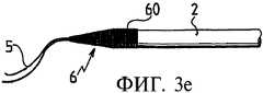
Как видно из Фиг.3 и в соответствии с другим важным аспектом изобретения, следующий этап установки наконечника 6 на оконечность 4 связки 1, снабженной натяжными нитями 5, состоит в наложении радиальной лигатуры 60 из лигатурной нити 7 на упомянутую связку.As can be seen from Figure 3 and in accordance with another important aspect of the invention, the next step in the installation of the
Эту лигатуру 60 выполняют в соответствии с последовательностью этапов, показанной на Фиг.3А-3Е.This
Первый этап выполнения лигатуры 60 состоит в формировании удлиненной петли 70 из лигатурной нити 7, сматываемой с катушки, и наложении упомянутой петли 70 на связку 1, при этом оба конца лигатурной нити параллельны связке и простираются наружу от оконечности 4 связки, на которую накладывают упомянутую лигатуру 60. Связка 1 при этом лежит на плоскости, предпочтительно зафиксированная соответствующим устройством, и петля 70 предпочтительно прижата к связке с помощью подвижного крючка 8. Этот подвижный крючок 8 является частью вышеупомянутого устройства для фиксации связки 1 на плоскости. Его преимуществом является возможность освобождения оператора, выполняющего лигатуру, от необходимости прижимать, например с помощью пальца, петлю 70 к связке 1 во время выполнения последующих операций наложения лигатуры.The first step in performing the
Затем берут один из концов нити 7, который становится при этом "подвижным" концом, и обматывают его одновременно вокруг связки и второго конца 72 лигатурной нити, называемого "неподвижным" (который при этом постоянно остается параллельным продольной оси связки 1), и вокруг петли 70, начиная с оконечности 4 связки и смещаясь в направлении к средней внутрисуставной части 3 связки, в направлении, указанном стрелкой 9 (Фиг.3В). При наматывании необходимо следить, чтобы витки подвижного конца 71 плотно прилегали друг к другу.Then they take one of the ends of the thread 7, which becomes a "movable" end, and wrap it simultaneously around the ligament and the
Далее подвижный конец 71 пропускают через петлю 70 и отцепляют последнюю от крючка 8, удерживавшего ее на месте, как показано на Фиг.3С. Как правило, этот этап выполняют, когда образовавшиеся витки перекрывают двойной узел натяжной нити 5 на уровне вхождения концов 51, 52 упомянутой нити 5 в толщу связки 1. Подразумевается, что поверхность, покрытую витками и, таким образом, размер лигатуры 60 можно менять в зависимости от конкретных требований к любому типу протезной связки, без выхода за пределы объема притязаний настоящего изобретения.Next, the
Затем всю совокупность элементов наконечника туго затягивают путем натягивания подвижного (71) и неподвижного (72) концов в направлениях, указанных стрелками 10 на Фиг.3D соответственно вдоль продольной оси связки для неподвижного конца 72 и в целом перпендикулярно этой оси для подвижного конца 71, сохраняя при этом плотное смыкание витков лигатуры.Then, the entire set of tip elements is tightly tightened by pulling the movable (71) and fixed (72) ends in the directions indicated by
Наконец, обрезают оба упомянутых конца заподлицо с поверхностью лигатуры 60 и получают, таким образом, наконечник 6 по настоящему изобретению, показанный на Фиг.3Е.Finally, both of these ends are cut flush with the surface of the
В соответствии с другим аспектом изобретения применяют лигатурную нить 7 из того же материала, что и синтетические волокна, образующие сетку связки 1. Обычно этим материалом является полиэтилентерефталат.In accordance with another aspect of the invention, a ligature yarn 7 of the same material as the synthetic fibers forming the net of the binder 1 is used. Typically, this material is polyethylene terephthalate.
Наконец, подразумевается, что способ по настоящему изобретению может быть адаптирован к любым другим формам связок, отличающимся от описанных, и что вышеописанные примеры являются лишь частными иллюстрациями, которые никоим образом не ограничивают области применения настоящего изобретения.Finally, it is understood that the method of the present invention can be adapted to any other forms of ligaments other than those described, and that the above examples are only particular illustrations, which in no way limit the scope of the present invention.
Claims (6)
Translated fromRussianподготовка натяжной нити (5) с формированием петли (50) вокруг тела связки 1 без перекрещивания концов нити вокруг связки и с расположением упомянутой петли (50) на некотором расстоянии от оконечности (4) связки (1);
введение в толщу связки (1) с диаметрально противоположных сторон петли (50) двух свободных концов (51, 52) натяжной нити (5) и их проталкивание в сторону соответствующей оконечности (4) в направлении, параллельном длине связки (1) до выхода наружу;
перекручивание петли (50) таким образом, чтобы образовалась фигура, подобная цифре 8, основание которой закреплено в связке (1), и пропускание оконечности (4) связки (1) со свободными концами (51, 52) натяжной нити (5) через вторую петлю (53), т.е. через меньшую часть восьмерки;
сдвигание обеих петель (50, 53) до уровня вхождения свободных концов (51, 52) в связку (1);
затягивание узла путем натягивания свободных концов (51, 52) натяжной нити 5.2. The method according to claim 1, characterized in that the fastening of the tension thread (5) is performed in the following sequence:
preparation of the tension thread (5) with the formation of a loop (50) around the body of the ligament 1 without crossing the ends of the thread around the ligament and with the location of the aforementioned loop (50) at some distance from the end (4) of the ligament (1);
introducing into the thickness of the ligament (1) from the diametrically opposite sides of the loop (50) two free ends (51, 52) of the tension thread (5) and pushing them towards the corresponding end (4) in a direction parallel to the length of the ligament (1) until it exits ;
twisting the loop (50) so that a figure similar to the figure 8 is formed, the base of which is fixed in the ligament (1), and passing the tip (4) of the ligament (1) with the free ends (51, 52) of the tension thread (5) through the second loop (53), i.e. through a smaller part of the eight;
the shift of both loops (50, 53) to the level of free ends (51, 52) entering the bundle (1);
tightening the assembly by pulling the free ends (51, 52) of the tension thread 5.
формирование удлиненной петли (70) из лигатурной нити (7) и наложение упомянутой петли (70) на связку (1), лежащую на плоскости, причем оба конца нити (7) параллельны связке (1) и простираются наружу от оконечности (4), на которой выполняют наконечник (6);
фиксирование петли (70) на связке (1);
наматывание одного из концов нити (7), называемого подвижным концом (71), одновременно вокруг связки и второго неподвижного конца (72) и вокруг петли (70), начиная с оконечности (4) связки и смещаясь в направлении к средней внутрисуставной части 3 связки, с формированием плотно прилегающих друг к другу витков;
пропускание подвижного конца (71) через петлю (70);
тугое затягивание совокупности элементов наконечника путем натяжения неподвижного (72) и подвижного (71) концов лигатурной нити при сохранении плотного смыкания витков лигатуры;
обрезка концов (71, 72) заподлицо с поверхностью радиальной лигатуры (60).4. The method according to claim 1, characterized in that the ligature (60) is performed in the following sequence:
the formation of an elongated loop (70) from the ligature thread (7) and the imposition of the aforementioned loop (70) on a bundle (1) lying on the plane, both ends of the thread (7) parallel to the bundle (1) and extend outward from the tip (4), on which perform the tip (6);
fixing the loop (70) on the ligament (1);
winding one of the ends of the thread (7), called the movable end (71), simultaneously around the ligament and the second fixed end (72) and around the loop (70), starting from the end (4) of the ligament and moving towards the middle intraarticular part 3 of the ligament , with the formation of tightly adjacent coils;
passing the movable end (71) through the loop (70);
tight tightening of the set of elements of the tip by tensioning the fixed (72) and movable (71) ends of the ligature yarn while maintaining tight closure of the ligature coils;
trim ends (71, 72) flush with the surface of the radial ligature (60).
Applications Claiming Priority (2)
| Application Number | Priority Date | Filing Date | Title |
|---|---|---|---|
| FR0400630AFR2865380B1 (en) | 2004-01-23 | 2004-01-23 | METHOD FOR ATTACHING TRACTION WIRES TO THE END OF A PROTHETIC LIGAMENT |
| FR0400630 | 2004-01-23 |
Publications (2)
| Publication Number | Publication Date |
|---|---|
| RU2006131415A RU2006131415A (en) | 2008-02-27 |
| RU2370243C2true RU2370243C2 (en) | 2009-10-20 |
Family
ID=34717368
Family Applications (1)
| Application Number | Title | Priority Date | Filing Date |
|---|---|---|---|
| RU2006131415/14ARU2370243C2 (en) | 2004-01-23 | 2005-01-21 | Method of fastening tension threads to prosthetic ligament |
Country Status (9)
| Country | Link |
|---|---|
| US (1) | US7494506B2 (en) |
| EP (1) | EP1715813B1 (en) |
| CN (1) | CN100542502C (en) |
| CA (1) | CA2553623C (en) |
| ES (1) | ES2423492T3 (en) |
| FR (1) | FR2865380B1 (en) |
| PL (1) | PL1715813T3 (en) |
| RU (1) | RU2370243C2 (en) |
| WO (1) | WO2005079707A1 (en) |
Families Citing this family (104)
| Publication number | Priority date | Publication date | Assignee | Title |
|---|---|---|---|---|
| US7195642B2 (en)* | 2001-03-13 | 2007-03-27 | Mckernan Daniel J | Method and apparatus for fixing a graft in a bone tunnel |
| US8512376B2 (en) | 2002-08-30 | 2013-08-20 | Arthrex, Inc. | Method and apparatus for internal fixation of an acromioclavicular joint dislocation of the shoulder |
| US9017381B2 (en) | 2007-04-10 | 2015-04-28 | Biomet Sports Medicine, Llc | Adjustable knotless loops |
| US8361113B2 (en) | 2006-02-03 | 2013-01-29 | Biomet Sports Medicine, Llc | Method and apparatus for coupling soft tissue to a bone |
| US8128658B2 (en) | 2004-11-05 | 2012-03-06 | Biomet Sports Medicine, Llc | Method and apparatus for coupling soft tissue to bone |
| US9801708B2 (en) | 2004-11-05 | 2017-10-31 | Biomet Sports Medicine, Llc | Method and apparatus for coupling soft tissue to a bone |
| US8298262B2 (en) | 2006-02-03 | 2012-10-30 | Biomet Sports Medicine, Llc | Method for tissue fixation |
| US7857830B2 (en)* | 2006-02-03 | 2010-12-28 | Biomet Sports Medicine, Llc | Soft tissue repair and conduit device |
| US7909851B2 (en) | 2006-02-03 | 2011-03-22 | Biomet Sports Medicine, Llc | Soft tissue repair device and associated methods |
| US7905904B2 (en) | 2006-02-03 | 2011-03-15 | Biomet Sports Medicine, Llc | Soft tissue repair device and associated methods |
| US8303604B2 (en) | 2004-11-05 | 2012-11-06 | Biomet Sports Medicine, Llc | Soft tissue repair device and method |
| US7749250B2 (en) | 2006-02-03 | 2010-07-06 | Biomet Sports Medicine, Llc | Soft tissue repair assembly and associated method |
| US8137382B2 (en) | 2004-11-05 | 2012-03-20 | Biomet Sports Medicine, Llc | Method and apparatus for coupling anatomical features |
| US8840645B2 (en) | 2004-11-05 | 2014-09-23 | Biomet Sports Medicine, Llc | Method and apparatus for coupling soft tissue to a bone |
| US7658751B2 (en) | 2006-09-29 | 2010-02-09 | Biomet Sports Medicine, Llc | Method for implanting soft tissue |
| US8118836B2 (en) | 2004-11-05 | 2012-02-21 | Biomet Sports Medicine, Llc | Method and apparatus for coupling soft tissue to a bone |
| US8088130B2 (en) | 2006-02-03 | 2012-01-03 | Biomet Sports Medicine, Llc | Method and apparatus for coupling soft tissue to a bone |
| US8998949B2 (en) | 2004-11-09 | 2015-04-07 | Biomet Sports Medicine, Llc | Soft tissue conduit device |
| US7899533B2 (en)* | 2005-10-25 | 2011-03-01 | Medtronic, Inc. | System and method of AV interval selection in an implantable medical device |
| US8574235B2 (en) | 2006-02-03 | 2013-11-05 | Biomet Sports Medicine, Llc | Method for trochanteric reattachment |
| US8562647B2 (en) | 2006-09-29 | 2013-10-22 | Biomet Sports Medicine, Llc | Method and apparatus for securing soft tissue to bone |
| US11259792B2 (en) | 2006-02-03 | 2022-03-01 | Biomet Sports Medicine, Llc | Method and apparatus for coupling anatomical features |
| US8652172B2 (en) | 2006-02-03 | 2014-02-18 | Biomet Sports Medicine, Llc | Flexible anchors for tissue fixation |
| US9149267B2 (en) | 2006-02-03 | 2015-10-06 | Biomet Sports Medicine, Llc | Method and apparatus for coupling soft tissue to a bone |
| US8771352B2 (en) | 2011-05-17 | 2014-07-08 | Biomet Sports Medicine, Llc | Method and apparatus for tibial fixation of an ACL graft |
| US8652171B2 (en) | 2006-02-03 | 2014-02-18 | Biomet Sports Medicine, Llc | Method and apparatus for soft tissue fixation |
| US9078644B2 (en) | 2006-09-29 | 2015-07-14 | Biomet Sports Medicine, Llc | Fracture fixation device |
| US11311287B2 (en) | 2006-02-03 | 2022-04-26 | Biomet Sports Medicine, Llc | Method for tissue fixation |
| US8968364B2 (en) | 2006-02-03 | 2015-03-03 | Biomet Sports Medicine, Llc | Method and apparatus for fixation of an ACL graft |
| US8562645B2 (en) | 2006-09-29 | 2013-10-22 | Biomet Sports Medicine, Llc | Method and apparatus for forming a self-locking adjustable loop |
| US8251998B2 (en)* | 2006-08-16 | 2012-08-28 | Biomet Sports Medicine, Llc | Chondral defect repair |
| US8801783B2 (en) | 2006-09-29 | 2014-08-12 | Biomet Sports Medicine, Llc | Prosthetic ligament system for knee joint |
| US9538998B2 (en) | 2006-02-03 | 2017-01-10 | Biomet Sports Medicine, Llc | Method and apparatus for fracture fixation |
| US9468433B2 (en) | 2006-02-03 | 2016-10-18 | Biomet Sports Medicine, Llc | Method and apparatus for forming a self-locking adjustable loop |
| US8597327B2 (en) | 2006-02-03 | 2013-12-03 | Biomet Manufacturing, Llc | Method and apparatus for sternal closure |
| US10517587B2 (en) | 2006-02-03 | 2019-12-31 | Biomet Sports Medicine, Llc | Method and apparatus for forming a self-locking adjustable loop |
| US8506597B2 (en) | 2011-10-25 | 2013-08-13 | Biomet Sports Medicine, Llc | Method and apparatus for interosseous membrane reconstruction |
| US9271713B2 (en) | 2006-02-03 | 2016-03-01 | Biomet Sports Medicine, Llc | Method and apparatus for tensioning a suture |
| US8500818B2 (en) | 2006-09-29 | 2013-08-06 | Biomet Manufacturing, Llc | Knee prosthesis assembly with ligament link |
| US11259794B2 (en) | 2006-09-29 | 2022-03-01 | Biomet Sports Medicine, Llc | Method for implanting soft tissue |
| US9918826B2 (en) | 2006-09-29 | 2018-03-20 | Biomet Sports Medicine, Llc | Scaffold for spring ligament repair |
| US8672969B2 (en) | 2006-09-29 | 2014-03-18 | Biomet Sports Medicine, Llc | Fracture fixation device |
| AU2007339257B2 (en)* | 2006-12-27 | 2013-01-10 | Shriners Hospitals For Children | Woven and/or braided fiber implants and methods of making same |
| US8858633B2 (en) | 2007-02-20 | 2014-10-14 | Shriners Hospital For Children | In vivo hydraulic fixation including bio-rivets using biocompatible expandable fibers |
| US20090131980A1 (en)* | 2007-11-20 | 2009-05-21 | Wiesman Irvin M | Tendon Cap and method for tendon repair |
| US9681869B2 (en)* | 2008-02-22 | 2017-06-20 | Mimedx Group, Inc. | Biostaples suitable for wrist, hand and other ligament replacements or repairs |
| WO2009139871A2 (en)* | 2008-05-16 | 2009-11-19 | Mimedx, Inc. | Medical constructs of twisted lengths of collagen fibers and methods of making same |
| US12245759B2 (en) | 2008-08-22 | 2025-03-11 | Biomet Sports Medicine, Llc | Method and apparatus for coupling soft tissue to bone |
| US12419632B2 (en) | 2008-08-22 | 2025-09-23 | Biomet Sports Medicine, Llc | Method and apparatus for coupling anatomical features |
| CA2740008C (en)* | 2008-10-09 | 2017-01-31 | Mimedx, Inc. | Methods of making biocomposite medical constructs and related constructs including artificial tissues, vessels and patches |
| EP2349089A4 (en)* | 2008-11-21 | 2014-01-15 | Lifecell Corp | Reinforced biologic material |
| US8460379B2 (en) | 2009-03-31 | 2013-06-11 | Arthrex, Inc. | Adjustable suture button construct and methods of tissue reconstruction |
| US8439976B2 (en)* | 2009-03-31 | 2013-05-14 | Arthrex, Inc. | Integrated adjustable button-suture-graft construct with two fixation devices |
| WO2010123835A1 (en)* | 2009-04-19 | 2010-10-28 | Slobodan Tepic | Suture attachment method and apparatus |
| US8343227B2 (en) | 2009-05-28 | 2013-01-01 | Biomet Manufacturing Corp. | Knee prosthesis assembly with ligament link |
| US12096928B2 (en) | 2009-05-29 | 2024-09-24 | Biomet Sports Medicine, Llc | Method and apparatus for coupling soft tissue to a bone |
| EP2455001B1 (en) | 2010-11-17 | 2020-07-22 | Arthrex, Inc. | Adjustable suture-button constructs for ligament reconstruction |
| EP2455002B1 (en) | 2010-11-17 | 2019-04-03 | Arthrex, Inc. | Adjustable suture-button construct for ankle syndesmosis repair |
| EP2455040B1 (en) | 2010-11-17 | 2015-03-04 | Arthrex, Inc. | Adjustable suture-button construct for knotless stabilization of cranial cruciate deficient ligament stifle |
| WO2012121986A2 (en) | 2011-03-08 | 2012-09-13 | Mimedx, Inc.. | Collagen fiber ribbons with integrated fixation sutures and methods of making the same |
| EP2699179B1 (en) | 2011-04-16 | 2023-06-07 | Kyon AG | Prosthetic system for orthopedic repair |
| US12329373B2 (en) | 2011-05-02 | 2025-06-17 | Biomet Sports Medicine, Llc | Method and apparatus for soft tissue fixation |
| US9694106B2 (en) | 2011-07-11 | 2017-07-04 | Mimedx Group, Inc. | Synthetic collagen threads for cosmetic uses including skin wrinkle treatments and associated methods |
| US9301745B2 (en) | 2011-07-21 | 2016-04-05 | Arthrex, Inc. | Knotless suture constructs |
| US9332979B2 (en) | 2011-07-22 | 2016-05-10 | Arthrex, Inc. | Tensionable knotless acromioclavicular repairs and constructs |
| FR2980101A1 (en)* | 2011-09-20 | 2013-03-22 | Tornier Inc | REINFORCING STRIP FOR THE RESTORATION OF A SOFT TISSUE |
| US9107653B2 (en) | 2011-09-22 | 2015-08-18 | Arthrex, Inc. | Tensionable knotless anchors with splice and methods of tissue repair |
| US10245016B2 (en) | 2011-10-12 | 2019-04-02 | Arthrex, Inc. | Adjustable self-locking loop constructs for tissue repairs and reconstructions |
| US8986378B2 (en) | 2011-11-02 | 2015-03-24 | Mimedx Group, Inc. | Implantable collagen devices and related methods and systems of making same |
| US9357991B2 (en) | 2011-11-03 | 2016-06-07 | Biomet Sports Medicine, Llc | Method and apparatus for stitching tendons |
| US9370350B2 (en) | 2011-11-10 | 2016-06-21 | Biomet Sports Medicine, Llc | Apparatus for coupling soft tissue to a bone |
| US9314241B2 (en) | 2011-11-10 | 2016-04-19 | Biomet Sports Medicine, Llc | Apparatus for coupling soft tissue to a bone |
| US9381013B2 (en) | 2011-11-10 | 2016-07-05 | Biomet Sports Medicine, Llc | Method for coupling soft tissue to a bone |
| EP2601894B1 (en) | 2011-12-09 | 2018-08-29 | Arthrex, Inc. | Tensionable knotless anchor systems |
| US9737292B2 (en) | 2012-06-22 | 2017-08-22 | Arthrex, Inc. | Knotless suture anchors and methods of tissue repair |
| CN102908210B (en)* | 2012-10-15 | 2015-06-17 | 复旦大学附属华山医院 | Single-hole suspended artificial ligament |
| CN102908211B (en)* | 2012-10-15 | 2015-07-22 | 复旦大学附属华山医院 | Integral annular suspension artificial ligament |
| US9757495B2 (en) | 2013-02-01 | 2017-09-12 | Children's Medical Center Corporation | Collagen scaffolds |
| US9757119B2 (en) | 2013-03-08 | 2017-09-12 | Biomet Sports Medicine, Llc | Visual aid for identifying suture limbs arthroscopically |
| US9918827B2 (en) | 2013-03-14 | 2018-03-20 | Biomet Sports Medicine, Llc | Scaffold for spring ligament repair |
| CN104043151B (en)* | 2013-03-15 | 2016-03-30 | 深圳兰度生物材料有限公司 | A kind of combined artificial ligament and preparation method thereof |
| EP3060167B1 (en) | 2013-10-25 | 2022-05-04 | Kyon AG | Holding and adjustment mechanism for surgical tether |
| US10136886B2 (en) | 2013-12-20 | 2018-11-27 | Biomet Sports Medicine, Llc | Knotless soft tissue devices and techniques |
| EP3104809B1 (en)* | 2014-02-13 | 2017-12-27 | Antonio Sambusseti | Non-absorbable tissue reconstruction device, in particular for tissues such as ligaments |
| US9615822B2 (en) | 2014-05-30 | 2017-04-11 | Biomet Sports Medicine, Llc | Insertion tools and method for soft anchor |
| US9700291B2 (en) | 2014-06-03 | 2017-07-11 | Biomet Sports Medicine, Llc | Capsule retractor |
| US10039543B2 (en) | 2014-08-22 | 2018-08-07 | Biomet Sports Medicine, Llc | Non-sliding soft anchor |
| US9955980B2 (en) | 2015-02-24 | 2018-05-01 | Biomet Sports Medicine, Llc | Anatomic soft tissue repair |
| US9974534B2 (en) | 2015-03-31 | 2018-05-22 | Biomet Sports Medicine, Llc | Suture anchor with soft anchor of electrospun fibers |
| US10265060B2 (en) | 2015-08-20 | 2019-04-23 | Arthrex, Inc. | Tensionable constructs with multi-limb locking mechanism through single splice and methods of tissue repair |
| US10335136B2 (en) | 2015-08-20 | 2019-07-02 | Arthrex, Inc. | Tensionable constructs with multi-limb locking mechanism through single splice and methods of tissue repair |
| US9931196B2 (en)* | 2015-08-26 | 2018-04-03 | Albert Einstein Healthcare Network | Connector for attaching tissue to bone |
| CN105496605A (en)* | 2015-12-04 | 2016-04-20 | 上海凯利泰医疗科技股份有限公司 | Double-bundle artificial ligament and manufacturing method, implanting device and implanting method thereof |
| US9504557B1 (en) | 2016-03-17 | 2016-11-29 | Allosource | High-strength allograft tendon construct |
| EP3361989B1 (en)* | 2016-03-17 | 2020-08-12 | AlloSource | High-strength allograft tendon construct |
| PL232907B1 (en)* | 2016-03-24 | 2019-08-30 | Robert Mrugas | Synthetic ligament, method for producing synthetic ligament and its application |
| CA3024196A1 (en)* | 2016-07-06 | 2018-01-11 | Children's Medical Center Corporation | Indirect method of articular tissue repair |
| CN106691628A (en)* | 2017-01-12 | 2017-05-24 | 赵金忠 | Integrated artificial bone ligament bone graft and preparation method thereof |
| US10646327B2 (en) | 2017-02-09 | 2020-05-12 | Arthrex, Inc. | Self-locking suture constructs and methods of tissue fixation |
| US10575842B2 (en) | 2017-02-09 | 2020-03-03 | Arthrex, Inc. | Knotless self-locking anchor constructs and methods of tissue fixation |
| CN107510520B (en)* | 2017-09-21 | 2020-08-11 | 上海松力生物技术有限公司 | Cruciate ligament regenerative implant and preparation method and application thereof |
| CN119770732A (en)* | 2020-12-21 | 2025-04-08 | 立心(深圳)医疗器械有限公司 | Artificial bone material, artificial ligament and preparation method of artificial ligament |
| US12194192B2 (en) | 2020-12-29 | 2025-01-14 | Industrial Technology Research Institute | Tissue scaffold for use in tendon and/or ligament |
| US20230103592A1 (en)* | 2021-10-01 | 2023-04-06 | Ahmadreza Afshar | Surgical device and method for repairing damaged flexor tendons |
Citations (4)
| Publication number | Priority date | Publication date | Assignee | Title |
|---|---|---|---|---|
| FR2710520A1 (en)* | 1993-09-28 | 1995-04-07 | Vidal Jean Jacques | Method for forming a rigid and flexible textile structure which has high resistance to traction and buckling and has good compression behaviour |
| FR2755846A1 (en)* | 1996-11-20 | 1998-05-22 | Jacques Philippe Laboureau | PRE-ORIENT PROSTHETIC LIGAMENT AND METHOD OF MAKING |
| RU2141281C1 (en)* | 1999-05-20 | 1999-11-20 | Малыгина Марина Александровна | Method of preparation of implants of ligaments and tendons |
| US6203572B1 (en)* | 1999-02-09 | 2001-03-20 | Linvatec Corporation | Device and method for ligament reconstruction |
Family Cites Families (8)
| Publication number | Priority date | Publication date | Assignee | Title |
|---|---|---|---|---|
| US3176316A (en)* | 1963-01-07 | 1965-04-06 | Bruce R Bodell | Plastic prosthetic tendon |
| US4187558A (en)* | 1977-10-25 | 1980-02-12 | Cutter Laboratories, Inc. | Prosthetic ligament |
| GB8304264D0 (en)* | 1983-02-16 | 1983-03-23 | Seedhom B B | Prosthetic ligament |
| JPH03505823A (en)* | 1987-08-19 | 1991-12-19 | イー・アイ・デユポン・デ・ニモアス・アンド・カンパニー | flexible tissue prosthesis |
| FR2697151B1 (en) | 1992-10-28 | 1994-12-23 | Laboureau Jacques Philippe | Artificial ligament and its method of making. |
| GB9306737D0 (en)* | 1993-03-31 | 1993-05-26 | Surgicarft Ltd | Ligament augmentation device |
| FR2729559B1 (en)* | 1995-01-25 | 1997-03-21 | Cousin Freres Sa | TEXTILE LIGAMENTARY REINFORCEMENT, PARTICULARLY FOR THE KNEE JOINT |
| US6752831B2 (en)* | 2000-12-08 | 2004-06-22 | Osteotech, Inc. | Biocompatible osteogenic band for repair of spinal disorders |
- 2004
- 2004-01-23FRFR0400630Apatent/FR2865380B1/ennot_activeExpired - Fee Related
- 2005
- 2005-01-21WOPCT/FR2005/000142patent/WO2005079707A1/enactiveApplication Filing
- 2005-01-21EPEP05717469.0Apatent/EP1715813B1/ennot_activeExpired - Lifetime
- 2005-01-21PLPL05717469Tpatent/PL1715813T3/enunknown
- 2005-01-21RURU2006131415/14Apatent/RU2370243C2/enactive
- 2005-01-21ESES05717469Tpatent/ES2423492T3/ennot_activeExpired - Lifetime
- 2005-01-21USUS10/586,362patent/US7494506B2/enactiveActive
- 2005-01-21CNCNB200580003010XApatent/CN100542502C/ennot_activeExpired - Lifetime
- 2005-01-21CACA2553623Apatent/CA2553623C/ennot_activeExpired - Lifetime
Patent Citations (4)
| Publication number | Priority date | Publication date | Assignee | Title |
|---|---|---|---|---|
| FR2710520A1 (en)* | 1993-09-28 | 1995-04-07 | Vidal Jean Jacques | Method for forming a rigid and flexible textile structure which has high resistance to traction and buckling and has good compression behaviour |
| FR2755846A1 (en)* | 1996-11-20 | 1998-05-22 | Jacques Philippe Laboureau | PRE-ORIENT PROSTHETIC LIGAMENT AND METHOD OF MAKING |
| US6203572B1 (en)* | 1999-02-09 | 2001-03-20 | Linvatec Corporation | Device and method for ligament reconstruction |
| RU2141281C1 (en)* | 1999-05-20 | 1999-11-20 | Малыгина Марина Александровна | Method of preparation of implants of ligaments and tendons |
Non-Patent Citations (1)
| Title |
|---|
| МОВШОВИЧ И.А. Оперативная ортопедия. - М.: Медицина, 1994, с.24-25. MATSUMOTO М. et al. Leeds-Keio artificial ligament: a new concept for the anterior cruciate ligament reconstruction of the knee. Keio J. Med. 2001 Sep; 50(3): 161-6 (abstract).* |
Also Published As
| Publication number | Publication date |
|---|---|
| US20070118217A1 (en) | 2007-05-24 |
| EP1715813A1 (en) | 2006-11-02 |
| CN100542502C (en) | 2009-09-23 |
| CN1909852A (en) | 2007-02-07 |
| CA2553623C (en) | 2012-07-24 |
| US7494506B2 (en) | 2009-02-24 |
| WO2005079707A1 (en) | 2005-09-01 |
| RU2006131415A (en) | 2008-02-27 |
| FR2865380A1 (en) | 2005-07-29 |
| FR2865380B1 (en) | 2006-03-03 |
| EP1715813B1 (en) | 2013-05-29 |
| PL1715813T3 (en) | 2013-09-30 |
| ES2423492T3 (en) | 2013-09-20 |
| CA2553623A1 (en) | 2005-09-01 |
Similar Documents
| Publication | Publication Date | Title |
|---|---|---|
| RU2370243C2 (en) | Method of fastening tension threads to prosthetic ligament | |
| US11278392B2 (en) | Method of making a continuous loop | |
| US12349896B2 (en) | Circular suture constructs and methods for use | |
| US9421085B2 (en) | Surgical methods for soft tissue repair | |
| US5456721A (en) | Device for reinforcing a ligament transplant during reconstructive surgery | |
| US9585654B2 (en) | Segmentally rigid suture and suturing technique | |
| US20100160962A1 (en) | Suturing construct with spliced tails | |
| US20120239145A1 (en) | Strong porous trans-tendon repair device with suture tails | |
| JPH03505823A (en) | flexible tissue prosthesis | |
| JP2009000523A (en) | Tubular prosthesis and associated kit | |
| JP2001524865A (en) | Loop mounting on perforated equipment | |
| US12310841B2 (en) | Fibrous connective tissue protective device, method of manufacturing, and surgical method | |
| CN112754730B (en) | Medical loop ring and manufacturing method thereof | |
| US20040243131A1 (en) | Bone fixing device | |
| EP1444959A1 (en) | Bone fixing device | |
| EP4477158A1 (en) | Suture structure for medical surgery and process for making the same | |
| KR20150129569A (en) | Extension Hair and Method of Operating The Same |