RU2366893C1 - Device for measurement of angular and linear coordinates of object - Google Patents
Device for measurement of angular and linear coordinates of objectDownload PDFInfo
- Publication number
- RU2366893C1 RU2366893C1RU2008106522/28ARU2008106522ARU2366893C1RU 2366893 C1RU2366893 C1RU 2366893C1RU 2008106522/28 ARU2008106522/28 ARU 2008106522/28ARU 2008106522 ARU2008106522 ARU 2008106522ARU 2366893 C1RU2366893 C1RU 2366893C1
- Authority
- RU
- Russia
- Prior art keywords
- lens
- angular
- coordinates
- segment
- linear
- Prior art date
Links
- 238000005259measurementMethods0.000titleabstractdescription20
- 230000011514reflexEffects0.000claimsabstractdescription8
- 230000010365information processingEffects0.000claimsabstractdescription5
- 238000003384imaging methodMethods0.000claimsdescription2
- 239000011159matrix materialSubstances0.000abstractdescription18
- 230000000694effectsEffects0.000abstract1
- 239000000126substanceSubstances0.000abstract1
- 238000006073displacement reactionMethods0.000description10
- 230000035945sensitivityEffects0.000description5
- 230000003287optical effectEffects0.000description4
- 238000004519manufacturing processMethods0.000description2
- 238000011089mechanical engineeringMethods0.000description2
- 210000001747pupilAnatomy0.000description2
- FMYKJLXRRQTBOR-BZSNNMDCSA-Nacetylleucyl-leucyl-norleucinalChemical compoundCCCC[C@@H](C=O)NC(=O)[C@H](CC(C)C)NC(=O)[C@H](CC(C)C)NC(C)=OFMYKJLXRRQTBOR-BZSNNMDCSA-N0.000description1
- 230000004075alterationEffects0.000description1
- 238000004364calculation methodMethods0.000description1
- 230000000739chaotic effectEffects0.000description1
- 238000010276constructionMethods0.000description1
- 238000010586diagramMethods0.000description1
- 238000005286illuminationMethods0.000description1
- 238000009434installationMethods0.000description1
- 239000004005microsphereSubstances0.000description1
- 230000005855radiationEffects0.000description1
- 230000002123temporal effectEffects0.000description1
- 238000001429visible spectrumMethods0.000description1
Images


Landscapes
- Length Measuring Devices By Optical Means (AREA)
Abstract
Description
Translated fromRussianИзобретение относится к области измерительной техники, к измерительным устройствам, характеризующимся оптическими средствами измерений, и может быть использовано для решения широкого круга технических задач, таких как сборка крупногабаритных конструкций, слежение за положением объекта, наведение на объект и ряде других.The invention relates to the field of measuring equipment, to measuring devices characterized by optical measuring instruments, and can be used to solve a wide range of technical problems, such as assembling large structures, tracking the position of an object, pointing at an object, and a number of others.
Традиционно дистанционные линейные измерения производятся при помощи визирных труб, а угловые измерения при помощи автоколлиматоров [Оптические приборы в машиностроении, справочник, М., Машиностроение, 1974, стр.122, 168]. При необходимости одновременного измерения линейных и угловых координат такие установки малоэффективны, а измерения на них трудоемки из-за наличия нескольких измерительных баз.Traditionally, remote linear measurements are made using sighting tubes, and angular measurements using auto-collimators [Optical devices in mechanical engineering, handbook, M., Mechanical Engineering, 1974, p. 122, 168]. If it is necessary to simultaneously measure linear and angular coordinates, such installations are ineffective, and measurements on them are laborious due to the presence of several measuring bases.
В технике также существует значительное количество контрольно-юстировочных задач, когда требуется дистанционно определять одновременно линейные и угловые координаты объекта. Это, например, контроль временного и температурного дрейфа объектов, наведение на мишень сфокусированного лазерного излучения и др. При необходимости одновременного измерения угловых и линейных координат объекта используются различные комбинации автоколлиматоров и визирных труб.In engineering, there are also a significant number of control and adjustment tasks when it is required to remotely determine simultaneously the linear and angular coordinates of an object. This, for example, control of the temporal and temperature drift of objects, guidance of focused laser radiation to a target, etc. If it is necessary to simultaneously measure the angular and linear coordinates of an object, various combinations of autocollimators and sighting tubes are used.
Известны устройства, объединяющие оба принципа работы и использующие один объектив, что позволяет получить одну измерительную базу и упростить интерпретацию результатов. Например, устройство для измерения угловых и линейных координат, выбранное нами в качестве прототипа [Repot LLNL, UCRL-LR-105821-97-3, стр.187, фигура 10], включающее два измерительных канала. Первый канал измерения угловых координат объекта работает следующим образом. Источник света освещает марку в виде перекрестия, установленную в фокальной плоскости объектива, затем световой луч проходит светоделитель, объектив, отражается от установленного на объекте контроля автоколлимационного зеркала с нанесенной на него второй рассеивающей маркой, проходит в обратном ходе объектив, отражается от поверхности светоделителя, проходит второй светоделитель и попадает на матричное фотоприемное устройство канала измерения угла. В плоскость фотоприемного устройства проецируется изображение первой марки, положение которой относительно координат фотоприемного устройства зависит от угла наклона автоколлимационного зеркала относительно оптической оси по двум взаимно перпендикулярным координатам. Данные с фотоприемника передаются в ЭВМ, которая по известным алгоритмам определяет положение изображения марки относительно координат приемника и рассчитывает угол поворота автоколлимационного зеркала (объекта) с учетом фокусного расстояния объектива и размера элемента матричного фотоприемника.Known devices that combine both operating principles and use a single lens, which allows to obtain one measuring base and simplify the interpretation of the results. For example, a device for measuring angular and linear coordinates, which we selected as a prototype [Repot LLNL, UCRL-LR-105821-97-3, p. 187, figure 10], including two measuring channels. The first channel for measuring the angular coordinates of the object works as follows. The light source illuminates the crosshair mark installed in the focal plane of the lens, then the light beam passes through the beam splitter, the lens is reflected from the autocollimation mirror installed on the control object with the second scattering mark applied to it, the lens passes in the opposite direction, is reflected from the beam splitter surface, passes the second beam splitter and gets on the matrix photodetector device of the angle measurement channel. An image of the first mark is projected onto the plane of the photodetector, the position of which relative to the coordinates of the photodetector depends on the angle of inclination of the autocollimation mirror relative to the optical axis in two mutually perpendicular coordinates. Data from the photodetector is transmitted to a computer, which according to known algorithms determines the position of the brand image relative to the coordinates of the receiver and calculates the angle of rotation of the autocollimation mirror (object) taking into account the focal length of the lens and the size of the element of the matrix photodetector.
Второй канал измерения линейных координат объекта работает так. Матричное фотоприемное устройство канала линейных измерений располагается таким образом, чтобы спроецировать изображение нанесенной на автоколлимационное зеркало второй рассеивающей марки в плоскость фотоприемника, при этом световой луч проходит через объектив, отражаясь от светоделительных поверхностей двух светоделителей. Подсветка второй рассеивающей марки производится тем же источником света через светоделитель и объектив. Координаты изображения рассеивающей марки относительно координат приемника канала линейных перемещений зависят от поперечного смещения марки в поле зрения объектива. Данные с фотоприемника передаются в ЭВМ, которая по известным алгоритмам определяет положение изображения второй рассеивающей марки относительно координат приемника и рассчитывает координаты второй марки (объекта) с учетом дистанции от объектива до марки (объекта), фокусного расстояния объектива и размера элемента матричного фотоприемника.The second channel for measuring the linear coordinates of the object works like this. The matrix photodetector of the linear measurement channel is positioned in such a way as to project the image of the second scattering mark applied to the autocollimation mirror into the plane of the photodetector, while the light beam passes through the lens, reflected from the beam-splitting surfaces of the two beam splitters. The backlight of the second scattering mark is produced by the same light source through a beam splitter and a lens. The coordinates of the image of the scattering mark relative to the coordinates of the receiver of the linear displacement channel depend on the lateral displacement of the mark in the field of view of the lens. Data from the photodetector is transmitted to a computer, which according to known algorithms determines the position of the image of the second scattering mark relative to the coordinates of the receiver and calculates the coordinates of the second mark (object) taking into account the distance from the lens to the mark (object), the focal length of the lens and the size of the element of the matrix photodetector.
Это устройство при достаточно высокой чувствительности как к угловому, так и к линейному перемещению объекта, имеет ряд существенных недостатков. Это, в первую очередь, малый диапазон угловых измерений, который связан с диаметром входного зрачка объектива при больших расстояниях до объекта. При больших дистанциях до объекта диаметр входного зрачка объектива определяется уже не необходимым разрешением (определяемым относительным отверстием объектива), а требуемым диапазоном работы канала измерения угла, что при увеличении диапазона измерений приводит к увеличению габаритов высокоточных оптических элементов. Например, при параметрах схемы, приведенной нами в качестве примера реализации изобретения (расстояние до объекта 4000 мм, диапазон угловых измерений ±4 угл.град), световой диаметр объектива прототипа составил бы не менее 560 мм.This device with a sufficiently high sensitivity to both angular and linear movement of the object, has a number of significant drawbacks. This is, first of all, a small range of angular measurements, which is associated with the diameter of the entrance pupil of the lens at large distances to the object. At large distances to the object, the diameter of the entrance pupil of the lens is no longer determined by the necessary resolution (determined by the relative aperture of the lens), but by the required range of operation of the angle measuring channel, which, with an increase in the measurement range, leads to an increase in the dimensions of high-precision optical elements. For example, with the parameters of the scheme given by us as an example of the invention (the distance to the object is 4000 mm, the range of angular measurements is ± 4 angular degrees), the light diameter of the prototype lens would be at least 560 mm.
Другими недостатками устройства являются значительные габариты и сложность схемы, связанные с наличием двух раздельных каналов угловых и линейных измерений.Other disadvantages of the device are the significant dimensions and complexity of the circuit associated with the presence of two separate channels of angular and linear measurements.
Нами предложено широкодиапазонное дистанционное устройство измерения угловых и линейных координат объекта. Устройство имеет простую в изготовлении конструкцию и уменьшенные массогабаритные характеристики.We have proposed a wide-range remote device for measuring the angular and linear coordinates of an object. The device has a simple construction to manufacture and reduced weight and size characteristics.
Такой технический результат достигнут нами, когда в устройстве измерения угловых и линейных координат объекта, содержащем осветитель, расположенные по ходу луча светоделитель, объектив, размещенную на объекте марку и установленный в сопряженной с объектом плоскости матричный фотоприемник с блоком обработки информации, причем осветитель установлен в фокальной плоскости объектива, новым является то, что марка выполнена в виде сегмента фокусирующего зеркала, расположенного на рефлексной поверхности, при этом фокусное расстояние сегмента фокусирующего зеркала не превышает величины глубины изображаемого пространства объектива.We achieved such a technical result when, in a device for measuring the angular and linear coordinates of an object containing a illuminator, a beam splitter located along the beam, a lens, a brand placed on the object, and a matrix photodetector with an information processing unit installed in the plane conjugated with the object, the illuminator is installed in the focal the lens plane, new is that the mark is made in the form of a segment of a focusing mirror located on a reflex surface, while the focal length of the segment a focusing mirror does not exceed the depth of the imaging lens space.
Зависимость глубины изображаемого пространства от параметров объектива и расстояния до объекта известна.The dependence of the depth of the imaged space on the parameters of the lens and the distance to the object is known.
В качестве сегмента фокусирующего зеркала марки может использоваться сегмент как вогнутого, так и выпуклого сферического или параболического зеркала. Параболическое зеркало может использоваться в большем диапазоне измеряемых углов, так как обладает меньшими полевыми аберрациями.As a segment of the brand’s focusing mirror, a segment of either a concave or convex spherical or parabolic mirror can be used. A parabolic mirror can be used in a larger range of measured angles, since it has less field aberrations.
Под рефлексной поверхностью понимается поверхность, характеризующаяся большим обратным отражением в широком диапазоне углов падения. Это может быть поверхность, покрытая микросферами, или шлифованая поверхность, покрытая отражающим слоем.Reflex surface refers to a surface characterized by a large back reflection in a wide range of angles of incidence. This may be a surface coated with microspheres, or a ground surface coated with a reflective layer.
На фиг.1а изображена функциональная схема устройства, на фиг.1б - марка увеличенного размера, где осветитель 1, светоделитель 2, объектив 3, марка 4, сегмент фокусирующего зеркала 5, рефлексная поверхность 6, объект 7, матричное фотоприемное устройство 8, блок 9 обработки информации.On figa shows a functional diagram of the device, on figb is an enlarged brand, where the illuminator 1, beam splitter 2, lens 3,
На фиг.2 приведено изображение марки и автоколлимационной точки сферического сегмента, снятое с матричного фотоприемника, где темное поле 10 является изображением сегмента фокусирующего зеркала 5, светлое пятно 11 на темном поле - изображением автоколлимационной точки сегмента фокусирующего зеркала 5, а хаотичная структура 12 - изображением рефлексной поверхности 6.Figure 2 shows the image of the mark and the autocollimation point of the spherical segment taken from the photodetector, where the
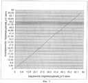
На фиг.3 приведены результаты измерения угловых перемещений объекта. На графике приведена зависимость измеренного угла (по оси ординат) от заданного угла(по оси абсцисс).Figure 3 shows the results of measuring the angular displacements of the object. The graph shows the dependence of the measured angle (along the ordinate) from a given angle (along the abscissa).
На фиг.4 приведены результаты измерения линейных перемещений объекта. На графике приведена зависимость измеренного перемещения (по оси ординат) от заданного перемещения (по оси абсцисс).Figure 4 shows the results of measuring linear displacements of the object. The graph shows the dependence of the measured displacement (along the ordinate) from a given displacement (along the abscissa).
Устройство измерения угловых и линейных координат объекта работает следующим образом.A device for measuring the angular and linear coordinates of an object works as follows.
Осветитель 1, установленный в фокальной плоскости объектива 3, через светоделитель 2 и объектив 3 освещает параллельным пучком марку 4, выполненную в виде сегмента фокусирующего зеркала 5, размещенного на рефлексной поверхности 6. Марка 4 установлена на объекте 7. Благодаря тому, что рефлексная поверхность 6 марки 4 возвращает значительную часть света по направлению освещения, а зеркало 5 вследствие выполнения его фокусирующим большую часть лучей отражает так, что они не попадают в апертуру объектива 3, в изображении на матричном фотоприемнике 8 образуется контур сегмента фокусирующего зеркала 5, положение которого относительно координат матрицы фотоприемника 8 позволяет рассчитывать линейные координаты объекта. Отраженный от поверхности сегмента фокусирующего зеркала 5 свет, попадающий в апертуру объектива 3, дает изображение 11 автоколлимационной точки. Изображения зеркального сегмента и автоколлимационной точки зеркала, разнесенные по глубине, проецируются объективом 3 в плоскость фотоприемника 8. Изображение, полученное с фотоприемника 8, приведено на фиг.2.The illuminator 1, mounted in the focal plane of the lens 3, through the beam splitter 2 and the lens 3 illuminates with a parallel beam a
Благодаря тому, что фокусное расстояние зеркального сегмента 5 выбирают меньше глубины изображаемого пространства объектива 3, в одной плоскости можно одновременно наблюдать изображение зеркального сегмента и автоколлимационной точки. Световой диаметр зеркального сегмента 5 выбирают, исходя из заданного диапазона изменений.Due to the fact that the focal length of the
Данные с фотоприемника 8 передаются в блок обработки информации 9 (ЭВМ) для последующего расчета.Data from the photodetector 8 is transmitted to the information processing unit 9 (computer) for subsequent calculation.
Для измерения двух линейных координат объекта используют определение положения центра изображения 10 сегмента фокусирующего зеркала 5 марки 4 относительно координат матричного фотоприемника 8. Для измерения двух угловых координат объекта используют определение положения изображения 11 автоколлимационной точки сегмента фокусирующего зеркала относительно центра изображения 10 сегмента 5 марки 4, изображенного на том же матричном фотоприемнике 8.To measure the two linear coordinates of the object, the position of the center of the
Данные с фотоприемника 8 передаются в ЭВМ 9, которая по известным алгоритмам определяет положение центра изображения контура сегмента фокусирующего зеркала 5 марки 4 относительно координат фотоприемника 8 и рассчитывает линейные координаты марки (объекта) с учетом дистанции от объектива 3 до марки 4 (объекта 7), фокусного расстояния объектива 3 и размера элемента матричного фотоприемника 8. ЭМВ также по известным алгоритмам определяет положение изображения автоколлимационной точки сегмента фокусирующего зеркала 5 относительно центра изображения сегмента фокусирующего зеркала 5 и рассчитывает угловые координаты марки 4 (объекта 7) с учетом фокусного расстояния сегмента фокусирующего зеркала 5 и размера элемента матричного фотоприемника 8. Диапазон измерения углов зависит от отношения светового диаметра сегмента фокусирующего зеркала к его фокусному расстоянию (чем больше фокусное расстояние, тем выше чувствительность и меньше диапазон работы). При этом надо учесть, что диапазон возможных фокусных расстояний сегмента фокусирующего зеркала 5 ограничен глубиной изображаемого пространства объектива 3 (например, для параметров схемы, приведенных в примере конкретного исполнения, он не должен превышать 100 мм).Data from the photodetector 8 is transmitted to a computer 9, which according to known algorithms determines the position of the center of the image of the contour of the segment of the focusing
Таким образом, с помощью изображения на одном матричном фотоприемнике дистанционно определяют две линейные и две угловые координаты объекта.Thus, using the image on one matrix photodetector, two linear and two angular coordinates of the object are remotely determined.
Во многих случаях применение дистанционного малогабаритного одноканального устройства одновременного измерения угловых и линейных координат с расширенным диапазоном измерений углов является предпочтительным, несмотря на некоторое уменьшение чувствительности измерения углов по сравнению с прототипом.In many cases, the use of a small-sized remote single-channel device for simultaneous measurement of angular and linear coordinates with an extended range of angle measurements is preferable, despite a slight decrease in the sensitivity of angle measurements compared to the prototype.
Пример конкретного исполнения устройства (см. фиг.1).An example of a specific implementation of the device (see figure 1).
В макете устройства в качестве осветителя использовался светодиод видимого диапазона спектра (длина волны 635 нм), объектив имел фокусное расстояние 1400 мм и световой диаметр 50 мм. Расстояние от объектива до марки (объекта) составляло 4000 мм, фокусное расстояние сегмента сферического фокусирующего зеркала марки равнялось 35 мм, световой диаметра сегмента - 5 мм. Параметры сегмента фокусирующего зеркала были выбраны, исходя из требований Заказчика по диапазону измерений углов (±4 угл.град), чувствительности в канале измерения угла (1 угл.мин) и размеру марки (диаметр не более 10 мм).In the device mockup, a visible-spectrum LED (wavelength 635 nm) was used as a illuminator, the lens had a focal length of 1400 mm and a light diameter of 50 mm. The distance from the lens to the brand (object) was 4000 mm, the focal length of the segment of the spherical focusing mirror of the brand was 35 mm, and the light diameter of the segment was 5 mm. The parameters of the focusing mirror segment were selected based on the customer's requirements for the range of measurements of angles (± 4 angular degrees), sensitivity in the channel for measuring the angle (1 angular min) and the size of the mark (diameter not more than 10 mm).
В качестве фотоприемника использовалась цифровая камера с матрицей формата 6,4×5,2 мм типа VAC-135 производства фирмы ЭВС, Санкт-Петербург. Данные с матричного фотоприемника передавались в ЭВМ типа Pentium-4 и обрабатывались при помощи корреляционных алгоритмов поиска центра координат изображения контура сегмента фокусирующего зеркала 5 и изображения автоколлимационной точки сегмента 5 относительно координат матричного фотоприемника. Затем полученные координаты изображения пересчитывались на координаты марки (объекта) с использованием известных зависимостей от дистанции, фокусного расстояния объектива, фокусного расстояния сегмента фокусирующего зеркала марки, размера элемента матричного приемника.As a photodetector, a digital camera with a 6.4 × 5.2 mm format matrix of the VAC-135 type manufactured by EVS, St. Petersburg was used. Data from the matrix photodetector was transferred to a Pentium-4 computer and processed using correlation algorithms for finding the center of coordinates of the image of the contour of the segment of the focusing
На созданном макете были определены основные параметры устройства (диапазон работы, чувствительность к угловым и линейным перемещениям объекта). При работе в качестве эталона был использован стенд, позволяющий с высокой точностью задавать линейные (1 мкм) и угловые (5 угл.с) перемещения марки.On the created layout, the basic parameters of the device were determined (operating range, sensitivity to angular and linear movements of the object). When working as a reference, a stand was used that allows one to set linear (1 μm) and angular (5 arc.s) mark movements with high accuracy.
Результаты определения параметров устройства приведены на фиг.3, 4.The results of determining the parameters of the device are shown in figure 3, 4.
Диапазон измерения линейных перемещений составил ±2,4 мм, среднеквадратичное отклонение при измерении линейных перемещений составило 1,9 мкм.The range of measurement of linear displacements was ± 2.4 mm, the standard deviation when measuring linear displacements was 1.9 μm.
Диапазон измерения угловых перемещений составил ±4 угл.град, среднеквадратичное отклонение при измерении угловых перемещений составило 0,38 угл.мин.The range of measuring angular displacements was ± 4 angular degrees, and the standard deviation when measuring angular displacements was 0.38 angular min.
Таким образом, предложено дистанционное устройство для одновременного определения двух линейных и двух угловых координат объекта при помощи одного матричного фотоприемника, обладающее большим диапазоном измерения углов, малыми габаритами и упрощенной конструкцией.Thus, the proposed remote device for the simultaneous determination of two linear and two angular coordinates of the object using one matrix photodetector, which has a large range of measurement of angles, small dimensions and simplified design.
В настоящее время по заданию Заказчика разработан комплект рабочей конструкторской документации для изготовления опытных образцов устройства.Currently, on the instructions of the Customer, a set of working design documentation for the manufacture of prototypes of the device has been developed.
Claims (1)
Translated fromRussianPriority Applications (1)
| Application Number | Priority Date | Filing Date | Title |
|---|---|---|---|
| RU2008106522/28ARU2366893C1 (en) | 2008-02-19 | 2008-02-19 | Device for measurement of angular and linear coordinates of object |
Applications Claiming Priority (1)
| Application Number | Priority Date | Filing Date | Title |
|---|---|---|---|
| RU2008106522/28ARU2366893C1 (en) | 2008-02-19 | 2008-02-19 | Device for measurement of angular and linear coordinates of object |
Publications (1)
| Publication Number | Publication Date |
|---|---|
| RU2366893C1true RU2366893C1 (en) | 2009-09-10 |
Family
ID=41166670
Family Applications (1)
| Application Number | Title | Priority Date | Filing Date |
|---|---|---|---|
| RU2008106522/28ARU2366893C1 (en) | 2008-02-19 | 2008-02-19 | Device for measurement of angular and linear coordinates of object |
Country Status (1)
| Country | Link |
|---|---|
| RU (1) | RU2366893C1 (en) |
Cited By (1)
| Publication number | Priority date | Publication date | Assignee | Title |
|---|---|---|---|---|
| RU2642999C2 (en)* | 2012-05-04 | 2018-01-29 | Салваньини Италия С.П.А. | Device and method of measuring bend angle of sheet |
Citations (1)
| Publication number | Priority date | Publication date | Assignee | Title |
|---|---|---|---|---|
| RU2117242C1 (en)* | 1996-07-04 | 1998-08-10 | Казанский государственный технический университет им.А.Н.Туполева | Method measuring position of object |
- 2008
- 2008-02-19RURU2008106522/28Apatent/RU2366893C1/enactive
Patent Citations (1)
| Publication number | Priority date | Publication date | Assignee | Title |
|---|---|---|---|---|
| RU2117242C1 (en)* | 1996-07-04 | 1998-08-10 | Казанский государственный технический университет им.А.Н.Туполева | Method measuring position of object |
Cited By (1)
| Publication number | Priority date | Publication date | Assignee | Title |
|---|---|---|---|---|
| RU2642999C2 (en)* | 2012-05-04 | 2018-01-29 | Салваньини Италия С.П.А. | Device and method of measuring bend angle of sheet |
Similar Documents
| Publication | Publication Date | Title |
|---|---|---|
| US10054439B2 (en) | Reflector arrangement with retroreflector and with a sensor arrangement for inclination determination and calibration | |
| US9766326B2 (en) | Laser tracker with calibration unit for self-calibration | |
| CN103403575B (en) | Target apparatus and method | |
| EP2201400B1 (en) | Wide field of view optical tracking system | |
| US6862097B2 (en) | Three-dimensional shape measuring method, and three-dimensional shape measuring apparatus | |
| EP2259010A1 (en) | Reference sphere detecting device, reference sphere position detecting device, and three-dimensional coordinate measuring device | |
| JP3631756B2 (en) | Optical device for determining the position of a reflective target mark | |
| NO164946B (en) | OPTO-ELECTRONIC SYSTEM FOR EXACTLY MEASURING A FLAT GEOMETRY. | |
| US7298468B2 (en) | Method and measuring device for contactless measurement of angles or angle changes on objects | |
| CN108168468B (en) | Focusing photoelectric auto-collimator with laser sighting device inside and sighting method | |
| JP6743788B2 (en) | Displacement sensor | |
| EP2793042B1 (en) | Positioning device comprising a light beam | |
| US20050275830A1 (en) | Surveying apparatus | |
| RU2612918C1 (en) | Device for determining positions of defects on aspherical surface of optical part (versions) | |
| US9297656B2 (en) | Sensor arrangement having code element | |
| CN1842691B (en) | Device with a measuring device that can be used with or without contact | |
| RU85226U1 (en) | CORNER INSTRUMENT | |
| US7545492B2 (en) | Sighting device and additional device for measuring, working, and/or operating with or without contact | |
| RU2366893C1 (en) | Device for measurement of angular and linear coordinates of object | |
| US20080130014A1 (en) | Displacement Measurement Sensor Using the Confocal Principle with an Optical Fiber | |
| RU2519512C1 (en) | Device to measure angular and linear coordinates of object | |
| JP3120885B2 (en) | Mirror surface measuring device | |
| SE530341C2 (en) | Method and apparatus for angular determination with retroreflective film | |
| RU2461797C1 (en) | Device to measure bend of artillery barrel | |
| EP4174436B1 (en) | Determination of the rotational position with an opto-electronic encoder with a ball lens |
Legal Events
| Date | Code | Title | Description |
|---|---|---|---|
| PC43 | Official registration of the transfer of the exclusive right without contract for inventions | Effective date:20121224 | |
| TK4A | Correction to the publication in the bulletin (patent) | Free format text:AMENDMENT TO CHAPTER -PC4A- IN JOURNAL: 4-2013 FOR TAG: (73) |