RU2364935C2 - Fingerprinting (scanner) device - Google Patents
Fingerprinting (scanner) deviceDownload PDFInfo
- Publication number
- RU2364935C2 RU2364935C2RU2007128157/09ARU2007128157ARU2364935C2RU 2364935 C2RU2364935 C2RU 2364935C2RU 2007128157/09 ARU2007128157/09 ARU 2007128157/09ARU 2007128157 ARU2007128157 ARU 2007128157ARU 2364935 C2RU2364935 C2RU 2364935C2
- Authority
- RU
- Russia
- Prior art keywords
- prism
- light
- lens
- objective
- cylindrical cavity
- Prior art date
Links
- 230000003287optical effectEffects0.000claimsabstractdescription8
- 239000011159matrix materialSubstances0.000claimsabstractdescription6
- 238000000149argon plasma sinteringMethods0.000claimsdescription2
- 230000000694effectsEffects0.000abstract1
- 230000003760hair shineEffects0.000abstract1
- 238000003384imaging methodMethods0.000abstract1
- 239000000126substanceSubstances0.000abstract1
- 230000004907fluxEffects0.000description1
- 238000005286illuminationMethods0.000description1
Images


Landscapes
- Image Input (AREA)
- Measurement Of The Respiration, Hearing Ability, Form, And Blood Characteristics Of Living Organisms (AREA)
Abstract
Description
Translated fromRussianНастоящее изобретение относится к цифровой обработке изображений и может быть использовано в устройствах, осуществляющих автоматическую аутентификацию или идентификацию личности.The present invention relates to digital image processing and can be used in devices that perform automatic authentication or identification.
Системы данного типа основаны на сканировании и последующей идентификации одного или нескольких биологических параметров человека, присущих только ему одному: радужной оболочки глаз, почерка, голоса и, наконец, отпечатков пальцев.Systems of this type are based on scanning and subsequent identification of one or several biological parameters of a person that are unique to him alone: the iris of the eye, handwriting, voice and, finally, fingerprints.
В настоящее время существуют различные биометрические системы распознавания личности по отпечаткам пальцев, основанные на использовании характерных деталей папиллярного узора (окончаний и ветвлений папиллярных линий отпечатков пальцев) [1, 2].Currently, there are various biometric fingerprint recognition systems based on the use of the characteristic details of the papillary pattern (endings and branches of papillary fingerprint lines) [1, 2].
Эффективность указанных систем распознавания личности зависит от точности выделения характерных деталей на цифровом изображении отпечатка пальца, уменьшения числа ложно выделенных характерных деталей за счет устранения из последующей обработки областей, принадлежащих фону, который, как правило, содержит шумы.The effectiveness of these personality recognition systems depends on the accuracy of distinguishing characteristic details on a digital image of a fingerprint, reducing the number of falsely distinguished characteristic details by eliminating from subsequent processing areas that belong to the background, which usually contains noise.
Наиболее близким техническим решением является устройство для снятия отпечатков пальцев [3], включающееThe closest technical solution is a device for fingerprinting [3], including
- первую призму, одна из поверхностей которой в одном направлении служит для снятия отпечатка пальца,- the first prism, one of the surfaces of which in one direction serves to take a fingerprint,
- источник света, проходящего через первую призму и используемого для освещения поверхности призмы для снятия отпечатка пальца,- a source of light passing through the first prism and used to illuminate the surface of the prism for fingerprinting,
- микроканал (пинхол), помещенный на пути света, отраженного от поверхности для снятия отпечатка пальца первой призмы, формирующий изображение отпечатка пальца первой призмы,- a microchannel (pinhole) placed in the path of light reflected from the surface for fingerprinting of the first prism, forming an image of the fingerprint of the first prism,
- плоскость изображения, созданную светом от первой призмы, проходящим через пинхол, располагаемую справа от пинхола,- the image plane created by the light from the first prism passing through the pinhole located to the right of the pinhole,
- вторую призму, помещенную между пинхолом и плоскостью изображения, имеющую выходную поверхность, параллельную плоскости снятия изображения пальца первой призмы, а вторую входную поверхность, параллельную выходной поверхности первой призмы и пинхолу.- a second prism placed between the pinhole and the image plane having an output surface parallel to the finger plane of the first prism, and a second input surface parallel to the output surface of the first prism and the pinhole.
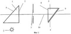
На фиг.1 представлена оптическая система прототипа: где 1 - первая призма с поверхностью для снятия отпечатков пальцев 6 и выходной поверхностью 7, 2 - источник света, 3 - пинхол, 4 - плоскость изображения, 5 - вторая призма с входной поверхностью 8 и выходной поверхностью 9, 10 - оптическая ось.Figure 1 shows the optical system of the prototype: where 1 is the first prism with a
Указанное устройство обладает рядом недостатков. Так разрешающая способность устройства ограничивается 300-400 точками на дюйм, что обусловлено низкой освещенностью из-за использования пинхола, а юстировка параллельных поверхностей требует громоздкого технического решения.The specified device has several disadvantages. So the resolution of the device is limited to 300-400 dpi, which is due to low light due to the use of a pinhole, and alignment of parallel surfaces requires a cumbersome technical solution.
Задачей настоящего изобретения является получение технического результата, заключающегося в повышении разрешающей способности устройства для снятия отпечатков пальцев до величины не менее чем 600 точек на дюйм и в сокращении времени юстировки системы за счет использования плосковыпуклой линзы, объектива, состоящего из нескольких линз с просветленной оптикой, и средства перемещения объектива.The objective of the present invention is to obtain a technical result, which consists in increasing the resolution of the device for fingerprinting to a value of not less than 600 dpi and in reducing the alignment time of the system through the use of a plano-convex lens, a lens consisting of several lenses with brightened optics, and means of moving the lens.
Для достижения указанного результата в устройство для снятия отпечатков пальцев [3], включающее:To achieve the specified result in the device for fingerprinting [3], including:
- призму, одна из поверхностей которой в одном направлении служит для снятия отпечатков пальцев,- a prism, one of the surfaces of which in one direction serves for fingerprinting,
- источник света, свет от которого проходит через призму и освещает поверхность призмы для снятия отпечатков пальцев,- a light source from which light passes through the prism and illuminates the surface of the prism for fingerprinting,
включают плосковыпуклую линзу, совмещенную с выходной поверхностью призмы, при этом призму используют с нижней матовой поверхностью, а источник света, состоящий из матрицы светодиодов, покрывают рассеивающей свет пленкой, объектив, состоящий из нескольких линз с просветленной оптикой, средство перемещения объектива в виде цилиндра, имеющего внутреннюю цилиндрическую полость с резьбой (отверстие), оси симметрии цилиндра и цилиндрической полости (отверстия) смещают относительно друг друга, объектив ввинчивают в цилиндрическую полость (отверстие), причем ось симметрии объектива соответствует оптической оси устройства и сенсора, принимающего изображение с объектива.include a plano-convex lens, combined with the output surface of the prism, the prism being used with a lower matte surface, and the light source, consisting of a matrix of LEDs, is coated with a light-scattering film, a lens, consisting of several lenses with an illuminated optics, a means of moving the lens in the form of a cylinder, having an internal cylindrical cavity with thread (hole), the axis of symmetry of the cylinder and the cylindrical cavity (hole) are displaced relative to each other, the lens is screwed into the cylindrical cavity (about aperture), and the axis of symmetry of the lens corresponds to the optical axis of the device and the sensor receiving the image from the lens.
Предлагаемое устройство представлено на фиг.2, где 1 - призма с поверхностью для снятия отпечатков пальцев 6 и выходной поверхностью 7 и матовой поверхностью 14, 15 - плосковыпуклая линза, 2 - источник света, представляющий собой матрицу светодиодов, свет которых рассеивается пленкой 16, 11 - объектив, состоящий из нескольких линз с просветленной оптикой, 12 - средство перемещения объектива, 13 - сенсор, 10 - оптическая ось.The proposed device is presented in figure 2, where 1 is a prism with a
Средство перемещения объектива 12 представлено на фиг.2, где средство в виде цилиндра имеет внутреннюю цилиндрическую полость с резьбой (отверстие). Оси симметрии цилиндра и цилиндрической полости (отверстия) смещены относительно друг друга. Объектив ввинчивается в цилиндрическую полость (отверстие). При вращении цилиндра цилиндр вращается с объективом, и поскольку ось симметрии цилиндра относительно оптической оси устройства не смещается, смещается объектив относительно оптической оси устройства.A means for moving the lens 12 is shown in FIG. 2, where the means in the form of a cylinder has an internal cylindrical cavity with a thread (hole). The axis of symmetry of the cylinder and the cylindrical cavity (hole) are offset relative to each other. The lens is screwed into a cylindrical cavity (hole). When the cylinder rotates, the cylinder rotates with the lens, and since the axis of symmetry of the cylinder relative to the optical axis of the device does not shift, the lens shifts relative to the optical axis of the device.
При повороте средства с объективом изображение отпечатка пальца смещается относительно сенсора по двум координатам, что обеспечивает возможность получения симметричного изображения на сенсоре.When you turn the tool with the lens, the fingerprint image is shifted relative to the sensor in two coordinates, which makes it possible to obtain a symmetric image on the sensor.
На фиг.3 демонстрируется положение пальца на плоскости 6 призмы 1, где 20 - место контакта выступа на пальце (папилляр), 17 - впадина на пальце, 18 - лучи света от источника света 2, поверхность пальца 19, 21 - свет, отраженный под разными углами.Figure 3 shows the position of the finger on the
Устройство работает следующим образом.The device operates as follows.
Рассеянный свет 18 (см. фиг.3) от матрицы светодиодов 2 попадает на плоскость 6 призмы 1. При этом свет, попавший на папилляр 20, отражается под разными углами 21 (как показано на фиг.3), и часть света, отраженного под определенным углом, попадает в объектив устройства и далее на сенсор.The scattered light 18 (see FIG. 3) from the matrix of
Свет, попавший на впадину 17 (между папиллярами), проходит через поверхность призмы и, рассеиваясь, не попадает в объектив и сенсор.The light entering the cavity 17 (between the papillaries) passes through the surface of the prism and, scattering, does not enter the lens and sensor.
В результате на сенсоре формируется изображение рисунка папилляров пальца, отождествляемое как отпечаток пальца.As a result, an image of a finger papillary pattern is formed on the sensor, identified as a fingerprint.
Повышение разрешающей способности устройства до величины не менее чем 600 точек на дюйм обеспечивается за счет следующих факторов:Increasing the resolution of the device to a value of not less than 600 dpi is ensured by the following factors:
1. достижения равномерного освещения плоскости для снятия отпечатков пальцев 6, что обеспечивается использованием матрицы светодиодов, рассеивающей пленки 16 и матовой поверхности 14 призмы,1. achieving uniform illumination of the
2. максимального использования (собирания) светового потока, отраженного от поверхности 6, с помощью плосковыпуклой линзы, совмещенной с выходной плоскостью призмы 7, и объектива, состоящего из нескольких линз с просветленной оптикой,2. maximum use (collection) of the light flux reflected from the
3. сохранения всей информации об отпечатке пальца за счет получения симметричного изображения на сенсоре, обеспечиваемого средством перемещения объектива.3. saving all information about the fingerprint by obtaining a symmetric image on the sensor provided by the means of moving the lens.
Снижение стоимости устройства обеспечивается тем обстоятельством, что в предлагаемом устройстве юстировка выполняется в одной плоскости, в то время как в прототипе в двух плоскостях.The reduction in the cost of the device is ensured by the fact that in the proposed device, the alignment is performed in one plane, while in the prototype in two planes.
Высокое качество получаемого изображения отпечатка пальца демонстрируется на фиг.4.The high quality of the obtained image of the fingerprint is shown in figure 4.
ЛитератураLiterature
1. Патент США № 5210588.1. US patent No. 5210588.
2. Патент США № 5233404.2. US Patent No. 5233404.
3. Патент США № 6463166.3. US Patent No. 6463166.
Claims (1)
Translated fromRussianPriority Applications (1)
| Application Number | Priority Date | Filing Date | Title |
|---|---|---|---|
| RU2007128157/09ARU2364935C2 (en) | 2007-07-24 | 2007-07-24 | Fingerprinting (scanner) device |
Applications Claiming Priority (1)
| Application Number | Priority Date | Filing Date | Title |
|---|---|---|---|
| RU2007128157/09ARU2364935C2 (en) | 2007-07-24 | 2007-07-24 | Fingerprinting (scanner) device |
Publications (2)
| Publication Number | Publication Date |
|---|---|
| RU2007128157A RU2007128157A (en) | 2009-01-27 |
| RU2364935C2true RU2364935C2 (en) | 2009-08-20 |
Family
ID=40543702
Family Applications (1)
| Application Number | Title | Priority Date | Filing Date |
|---|---|---|---|
| RU2007128157/09ARU2364935C2 (en) | 2007-07-24 | 2007-07-24 | Fingerprinting (scanner) device |
Country Status (1)
| Country | Link |
|---|---|
| RU (1) | RU2364935C2 (en) |
Cited By (3)
| Publication number | Priority date | Publication date | Assignee | Title |
|---|---|---|---|---|
| RU2484524C1 (en)* | 2012-05-21 | 2013-06-10 | Общество С Ограниченной Ответственностью "Абилма" | System for recording papillary patterns |
| RU2532712C1 (en)* | 2010-09-28 | 2014-11-10 | Нек Инджиниринг, Лтд. | Image reading device and image reading method |
| RU2562374C2 (en)* | 2011-01-27 | 2015-09-10 | Нек Инджиниринг, Лтд. | Image reader |
Citations (5)
| Publication number | Priority date | Publication date | Assignee | Title |
|---|---|---|---|---|
| US5210588A (en)* | 1990-11-17 | 1993-05-11 | Goldstar Co., Ltd. | Fingerprint identification apparatus for enhancing identification performance by forming an illumination source and a light conducting panel in a single body |
| US5233404A (en)* | 1989-09-28 | 1993-08-03 | Oscan Electro Optics Inc. | Optical scanning and recording apparatus for fingerprints |
| RU2022524C1 (en)* | 1992-05-28 | 1994-11-15 | Ищенко Никита Владимирович | Device for recording print of fingers |
| US20020097896A1 (en)* | 1998-03-17 | 2002-07-25 | Lars Kuckendahl | Device and method for scanning and mapping a surface |
| US6463166B1 (en)* | 1996-12-06 | 2002-10-08 | Yamatake-Honeywell Co., Ltd. | Fingerprint input apparatus |
- 2007
- 2007-07-24RURU2007128157/09Apatent/RU2364935C2/ennot_activeIP Right Cessation
Patent Citations (5)
| Publication number | Priority date | Publication date | Assignee | Title |
|---|---|---|---|---|
| US5233404A (en)* | 1989-09-28 | 1993-08-03 | Oscan Electro Optics Inc. | Optical scanning and recording apparatus for fingerprints |
| US5210588A (en)* | 1990-11-17 | 1993-05-11 | Goldstar Co., Ltd. | Fingerprint identification apparatus for enhancing identification performance by forming an illumination source and a light conducting panel in a single body |
| RU2022524C1 (en)* | 1992-05-28 | 1994-11-15 | Ищенко Никита Владимирович | Device for recording print of fingers |
| US6463166B1 (en)* | 1996-12-06 | 2002-10-08 | Yamatake-Honeywell Co., Ltd. | Fingerprint input apparatus |
| US20020097896A1 (en)* | 1998-03-17 | 2002-07-25 | Lars Kuckendahl | Device and method for scanning and mapping a surface |
Cited By (4)
| Publication number | Priority date | Publication date | Assignee | Title |
|---|---|---|---|---|
| RU2532712C1 (en)* | 2010-09-28 | 2014-11-10 | Нек Инджиниринг, Лтд. | Image reading device and image reading method |
| RU2562374C2 (en)* | 2011-01-27 | 2015-09-10 | Нек Инджиниринг, Лтд. | Image reader |
| RU2484524C1 (en)* | 2012-05-21 | 2013-06-10 | Общество С Ограниченной Ответственностью "Абилма" | System for recording papillary patterns |
| WO2013176573A1 (en)* | 2012-05-21 | 2013-11-28 | Общество С Ограниченной Ответственностью "Абилма" | Papillary ridge pattern registration system |
Also Published As
| Publication number | Publication date |
|---|---|
| RU2007128157A (en) | 2009-01-27 |
Similar Documents
| Publication | Publication Date | Title |
|---|---|---|
| US6429927B1 (en) | Imaging device, especially for optical fingerprinting | |
| US7747046B2 (en) | Apparatus and method for obtaining images using a prism | |
| CA2552650C (en) | Low power fingerprint capture system, apparatus, and method | |
| CN100376922C (en) | Personal identification device and fingerprint image capturing method | |
| CN103929566B (en) | Biometric information image capture apparatus and biometrics authentication apparatus | |
| US20070035718A1 (en) | Non-contact optical imaging system for biometric identification | |
| WO2001065471A1 (en) | Method and apparatus for distinguishing a human finger from a reproduction of a fingerprint | |
| US20050249390A1 (en) | Method and apparatus for discriminating ambient light in a fingerprint scanner | |
| EP1644870B1 (en) | System and method for illuminating a platen in a live scanner and producing high-contrast print images | |
| JP2009009403A (en) | Biometric authentication device and biometric detection method | |
| EP1643415B1 (en) | Fingerprint image pickup device | |
| TW201824077A (en) | Biometric identification apparatus | |
| US8811690B2 (en) | Imaging device having a prismatic element | |
| RU2364935C2 (en) | Fingerprinting (scanner) device | |
| TWM553454U (en) | Biometric identification apparatus | |
| JPH09134419A (en) | Fingerprint illumination method and fingerprint imaging device | |
| JP2009069981A (en) | Biological image input device and personal authentication system using the same | |
| CN111310742B (en) | Ultrathin fingerprint acquisition device | |
| JPH08279035A (en) | Fingerprint input device | |
| DE602004004926D1 (en) | OPTICAL IMAGING APPARATUS SUITABLE FOR PRODUCING AN IMAGE OF FINGERPRINTS | |
| RU2185096C1 (en) | Device recording papillary pattern | |
| US7426020B2 (en) | System for print imaging with prism illumination optics | |
| JP2020086749A (en) | Imaging device and imaging method | |
| US7221489B2 (en) | Live print scanner with holographic platen | |
| JP2008527544A (en) | Biometric recognition / verification using multispectral imaging |
Legal Events
| Date | Code | Title | Description |
|---|---|---|---|
| MM4A | The patent is invalid due to non-payment of fees | Effective date:20110725 |