RU2363896C1 - Instrument for heat and humidity treatment of air - Google Patents
Instrument for heat and humidity treatment of airDownload PDFInfo
- Publication number
- RU2363896C1 RU2363896C1RU2008116671/06ARU2008116671ARU2363896C1RU 2363896 C1RU2363896 C1RU 2363896C1RU 2008116671/06 ARU2008116671/06 ARU 2008116671/06ARU 2008116671 ARU2008116671 ARU 2008116671ARU 2363896 C1RU2363896 C1RU 2363896C1
- Authority
- RU
- Russia
- Prior art keywords
- air
- stage
- heat
- mixing chamber
- pipeline
- Prior art date
Links
- 239000007788liquidSubstances0.000claimsabstractdescription15
- XLYOFNOQVPJJNP-UHFFFAOYSA-NwaterSubstancesOXLYOFNOQVPJJNP-UHFFFAOYSA-N0.000claimsabstractdescription14
- 230000002262irrigationEffects0.000claimsabstractdescription11
- 238000003973irrigationMethods0.000claimsabstractdescription11
- 239000000428dustSubstances0.000claimsabstractdescription6
- 239000012530fluidSubstances0.000claimsabstractdescription4
- 238000012545processingMethods0.000claimsdescription6
- 238000005057refrigerationMethods0.000claimsdescription3
- 238000012546transferMethods0.000claimsdescription2
- 238000004378air conditioningMethods0.000abstractdescription4
- 238000004140cleaningMethods0.000abstractdescription3
- 238000013461designMethods0.000abstractdescription2
- 241001589086Bellapiscis mediusSpecies0.000abstract2
- 230000000694effectsEffects0.000abstract1
- 239000000126substanceSubstances0.000abstract1
- 238000000034methodMethods0.000description2
- 230000003134recirculating effectEffects0.000description2
- 238000005507sprayingMethods0.000description2
- 230000001174ascending effectEffects0.000description1
- 230000015572biosynthetic processEffects0.000description1
- 238000009833condensationMethods0.000description1
- 230000005494condensationEffects0.000description1
- 238000001816coolingMethods0.000description1
- 238000010586diagramMethods0.000description1
- 238000009434installationMethods0.000description1
- 238000012423maintenanceMethods0.000description1
- 238000004519manufacturing processMethods0.000description1
- 230000002093peripheral effectEffects0.000description1
- 238000011084recoveryMethods0.000description1
- 238000004064recyclingMethods0.000description1
- 230000001172regenerating effectEffects0.000description1
- 239000010979rubySubstances0.000description1
- 229910001750rubyInorganic materials0.000description1
- 229910052594sapphireInorganic materials0.000description1
- 239000010980sapphireSubstances0.000description1
- 238000007789sealingMethods0.000description1
- 239000011343solid materialSubstances0.000description1
- 239000007921spraySubstances0.000description1
- 238000004544sputter depositionMethods0.000description1
- UONOETXJSWQNOL-UHFFFAOYSA-Ntungsten carbideChemical compound[W+]#[C-]UONOETXJSWQNOL-UHFFFAOYSA-N0.000description1
- 238000009423ventilationMethods0.000description1
Images

Landscapes
- Central Air Conditioning (AREA)
Abstract
Description
Translated fromRussianИзобретение относится к системам вентиляции и кондиционирования воздуха с режимами регенеративной теплоутилизации и может быть использовано для создания комфортных условий микроклимата в бытовых, административных и производственных помещениях.The invention relates to ventilation and air conditioning systems with regenerative heat recovery modes and can be used to create comfortable microclimate conditions in domestic, administrative and industrial premises.
Наиболее близким техническим решением к заявляемому объекту в части устройства является устройство для обработки воздуха по патенту РФ №2319906, F24F 5/00 от 13.10.06 (прототип), содержащее камеру смешения, подогреватель и блок орошения.The closest technical solution to the claimed object in terms of the device is a device for air treatment according to the patent of the Russian Federation No. 2319906, F24F 5/00 from 10/13/06 (prototype), containing a mixing chamber, a heater and an irrigation unit.
Недостатком прототипа является сравнительно невысокая эффективность процесса тепловлажностной обработки воздуха за счет недостаточной эффективности очистки рециркуляционного воздуха от тонкой пыли и невозможности подмеса воздуха других параметров уже после обработки рециркуляционного ввиду отсутствия вихревой камеры смешения.The disadvantage of the prototype is the relatively low efficiency of the process of heat-moisture processing of air due to the insufficient efficiency of cleaning recirculated air from fine dust and the inability to mix air with other parameters after processing the recirculation due to the absence of a vortex mixing chamber.
Технический результат - повышение эффективности тепловлажностной обработки воздуха, экономия энергоресурсов, упрощение конструкции систем кондиционирования воздуха, их монтажа и обслуживания.The technical result is an increase in the efficiency of heat-moisture processing of air, energy savings, simplification of the design of air conditioning systems, their installation and maintenance.
Это достигается тем, что в аппарате для тепловлажностной обработки воздуха, содержащим камеру смешения, подогреватель и блок орошения, первая ступень представляет собой многофункциональный аппарат со встречными закрученными потоками и предназначена для очистки от пыли рециркуляционного воздуха, поступающего из помещения и имеющего положительную температуру, а также для увлажнения воздуха, и включает в себя корпус с емкостью для сбора жидкости, в которой расположен насос с фильтром для осуществления рециркуляции жидкости по трубопроводу и подачи ее в блок орошения, который выполнен в виде, по крайней мере, двух круговых трубчатых коллекторов с равномерно распределенными по внутренней поверхности центробежными форсунками, при этом трубопровод для рециркуляции жидкости содержит регулирующий клапан-смеситель для подключения к системе водоснабжения посредством трубопровода к источнику подачи охлажденной воды от холодильной машины, а в нижней части корпуса расположен нижний входной патрубок, а в верхней части - верхний входной патрубок, а в патрубках установлены соответственно нижний тангенциальный закручиватель и верхний тангенциальный закручиватель, при этом выхлопной патрубок соединяет первую ступень устройства со второй ступенью устройства, предназначенной для смешения потоков воздуха, поступающих из первой ступени с потоком наружного воздуха, причем вторая ступень устройства выполнена в виде тепломассообменного аппарата смешения и включает в себя входной патрубок камеры смешения, центробежную камеру смешения, диффузор, конфузор, раскручиватель, выходной патрубок.This is achieved by the fact that in the apparatus for heat-humidity processing of air containing a mixing chamber, a heater and an irrigation unit, the first stage is a multifunctional apparatus with counter swirling flows and is designed to clean the dust from the recirculated air coming from the room and having a positive temperature, and for humidification of air, and includes a housing with a container for collecting liquid, in which there is a pump with a filter for recycling liquid through pipelines an ode and its supply to the irrigation unit, which is made in the form of at least two circular tubular collectors with centrifugal nozzles evenly distributed on the inner surface, while the pipeline for recirculating the liquid contains a control valve mixer for connecting to the water supply system through a pipeline to the source supply of chilled water from the chiller, and the lower inlet pipe is located in the lower part of the housing, and the upper inlet pipe is located in the upper part, and the corresponding the lower tangential swirl and the upper tangential swirl, while the exhaust pipe connects the first stage of the device to the second stage of the device, designed to mix the air flows coming from the first stage with the flow of external air, and the second stage of the device is made in the form of a heat and mass mixing apparatus and includes self inlet pipe of the mixing chamber, centrifugal mixing chamber, diffuser, confuser, straightener, outlet pipe.
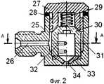
На фиг.1 представлена схема аппарата для тепловлажностной обработки воздуха, на фиг.2 - общий вид форсунки для распыливания жидкостей, на фиг.3 - разрез А-А фиг.2.Figure 1 presents a diagram of an apparatus for heat-moisture treatment of air, figure 2 is a General view of the nozzle for spraying liquids, figure 3 is a section aa of figure 2.
Аппарат для тепловлажностной обработки воздуха (фиг.1) состоит из двух ступеней: первая ступень представляет собой многофункциональный аппарат со встречными закрученными потоками и предназначена для очистки от пыли рециркуляционного воздуха, поступающего из помещения и имеющего положительную температуру, а также для увлажнения воздуха, и включает в себя корпус 1 с емкостью 2 для сбора жидкости, в которой расположен насос 20 с фильтром 19 для осуществления рециркуляции жидкости по трубопроводу 21 и подачи ее в блок орошения 5, который выполнен в виде, по крайней мере, двух круговых трубчатых коллекторов с равномерно распределенными по внутренней поверхности центробежными форсунками (фиг.2, 3). Трубопровод 21 для рециркуляции жидкости содержит регулирующий клапан-смеситель 22 для подключения к системе водоснабжения посредством трубопровода 23 к источнику 24 подачи охлажденной воды от холодильной машины, или артезианской скважины, или емкости с запасом ледниковой воды.The apparatus for heat-moisture treatment of air (Fig. 1) consists of two steps: the first step is a multifunctional apparatus with counter-swirling flows and is designed to clean the dust from the recirculated air coming from the room and having a positive temperature, as well as to humidify the air, and includes includes a housing 1 with a container 2 for collecting liquid, in which a pump 20 with a filter 19 is located for recirculating the liquid through the pipe 21 and supplying it to the irrigation unit 5, which n in the form of at least two circular tubular manifolds with centrifugal nozzles uniformly distributed over the inner surface (FIGS. 2, 3). The liquid recirculation pipe 21 comprises a control valve mixer 22 for connecting to a water supply system via a pipe 23 to a chilled water supply 24 from a refrigeration machine, or an artesian well, or a container with a glacial water supply.
В нижней части корпуса 1 расположен нижний входной патрубок 18, а в верхней части - верхний входной патрубок 17. Для интенсификации процесса тепловлажностной обработки воздуха в патрубках установлены соответственно нижний тангенциальный закручиватель 3 и верхний тангенциальный закручиватель 4.The lower inlet pipe 18 is located in the lower part of the housing 1, and the upper inlet pipe 17 is in the upper part. To intensify the process of heat-humidity treatment of air, the lower tangential swirl 3 and the upper tangential swirl 4 are installed in the nozzles, respectively.
Выхлопной патрубок 6 соединяет первую ступень устройства со второй ступенью устройства, предназначенной для смешения потоков воздуха, поступающих из первой ступени с потоком наружного воздуха, имеющего в летний период положительную температуру, а в зимний - отрицательную. Вторая ступень устройства выполнена в виде тепломассообменного аппарата смешения и включает в себя: входной патрубок камеры смешения 7, центробежную камеру смешения 8, диффузор 9, конфузор 10, раскручиватель 11, выходной патрубок 12. Потоки воздуха 13 и 14 - это рециркуляционные потоки воздуха, 15 - поток наружного воздуха, 16 - поток обработанного воздуха. Центробежная камера смешения 8 выполнена по габаритному внешнему размеру - диаметру D, больше, чем габаритный внешний размер корпуса 1 многофункционального аппарата - диаметр D1. Для оптимальной работы аппарата необходимо выполнить следующие соотношения параметров:An exhaust pipe 6 connects the first stage of the device with the second stage of the device, designed to mix the air flows coming from the first stage with the flow of external air, which has a positive temperature in summer and a negative temperature in winter. The second stage of the device is made in the form of a heat and mass transfer apparatus for mixing and includes: the inlet pipe of the mixing chamber 7, the centrifugal mixing chamber 8, the diffuser 9, the confuser 10, the spinner 11, the outlet pipe 12. The air flows 13 and 14 are recirculated air flows, 15 - a stream of external air, 16 - a stream of treated air. The centrifugal mixing chamber 8 is made according to the overall external size - diameter D, larger than the overall external size of the housing 1 of the multifunctional apparatus - diameter D1 . For optimal operation of the device, it is necessary to perform the following ratio of parameters:
- отношение диаметра D центробежной камеры смешения 8 к диаметру D1 корпуса многофункционального аппарата лежит в оптимальном интервале величин: D/D1=1,25-2,0;- the ratio of the diameter D of the centrifugal mixing chamber 8 to the diameter D1 of the casing of the multifunctional apparatus lies in the optimal range of values: D / D1 = 1.25-2.0;
- угол наклона форсунок блока орошения 5 к горизонту лежит в оптимальном интервале величин: 30÷40°;- the angle of the nozzles of the irrigation unit 5 to the horizon lies in the optimal range of values: 30 ÷ 40 °;
- аэродинамическое сопротивление аппарата лежит в оптимальном интервале величин: 600÷900 Па.- aerodynamic drag of the apparatus lies in the optimal range of values: 600 ÷ 900 Pa.
Центробежная форсунка (фиг.2-3) состоит из корпуса 25 с впускным отверстием 26 крышки 27 герметизирующей прокладки 28 между корпусом и крышкой, пружины 29, расположенной между крышкой и завихрителем 30, выполненным в виде перевернутого днищем вверх цилиндрического стакана, установленного относительно корпуса 25 с кольцевым зазором 31. В завихрителе 30 выполнено, по меньшей мере, два ряда дроссельных отверстий 32, в каждом ряду выполнено, по меньшей мере, два равномерно расположенных по кольцевой стенке завихрителя 30 дроссельных отверстия 32. В нижней части корпуса 25 установлен в виде конической шайбы сопловый вкладыш 33, выполненный из твердых материалов: карбида вольфрама, рубина, сапфира с калиброванным коническим отверстием 34, соосным с цилиндрической поверхностью завихрителя 30, причем отверстие 34 имеет обратную конусность с конической шайбой вкладыша 33.The centrifugal nozzle (Fig.2-3) consists of a
Аппарат для тепловлажностной обработки воздуха работает следующим образом.Apparatus for heat-moisture treatment of air works as follows.
В многофункциональном аппарате со встречными закрученными потоками в рабочем пространстве первой ступени образуются, как и в классическом аппарате со встречными закрученными потоками, два закрученных в одну сторону, но встречно направленных потока: восходящий - в центральной части камеры и нисходящий - в периферийной части. Для тепловлажностной обработки воздуха в блок орошения 5 по трубопроводу 21 подается вода, распыляемая центробежными тангенциальными форсунками. Под действием центробежных сил капли воды отбрасываются на вертикальные стенки аппарата и по ним стекают в нижнюю часть камеры. Затем увлажненный воздух выводится из камеры через выхлопной патрубок 6, расположенный в верхней части первой ступени аппарата, и поступает в камеру смешения - вторую ступень устройства. Часть наружного воздуха, заранее подготовленная в системе кондиционирования воздуха, через тангенциальный закручиватель входного патрубка камеры смешения 7 подается в центробежную камеру смешения 8, где поток увлажненного и очищенного от пыли воздуха смешивается с наружным потоком воздуха. Увеличение диаметра D камеры смешения 8 относительно диаметра D1 корпуса 1 многофункционального аппарата первой ступени устройства, где происходит увлажнение и мокрое обеспыливание, обеспечивает падение скорости воздуха в поперечном сечении аппарата и, как следствие, не создается существенного дополнительного аэродинамического сопротивления, что способствует предотвращению каплеуноса. На выходе из аппарата второй ступени установлен раскручиватель 11 обработанного потока воздуха. Посредством регулирующего клапана-смесителя 22 осуществляется подключение аппарата к системе водоснабжения от источника 24 подачи охлажденной воды от холодильной машины, или артезианской скважины, или емкости с запасом ледниковой воды, что позволяет эффективно использовать аппарат в летнее время для процессов одновременного увлажнения и охлаждения обрабатываемого воздуха, подаваемого в помещения.In a multifunctional apparatus with counter-swirling flows in the first stage workspace, two swirling in one direction but opposite directions are formed, as in the classic apparatus with counter-swirling flows: ascending in the central part of the chamber and descending in the peripheral part. For heat-moisture treatment of air in the irrigation unit 5 through the pipe 21, water is sprayed by centrifugal tangential nozzles. Under the action of centrifugal forces, water droplets are thrown onto the vertical walls of the apparatus and flow down into the lower part of the chamber. Then the humidified air is discharged from the chamber through the exhaust pipe 6, located in the upper part of the first stage of the apparatus, and enters the mixing chamber - the second stage of the device. Part of the outdoor air prepared in advance in the air conditioning system, through the tangential curler of the inlet pipe of the mixing chamber 7, is supplied to the centrifugal mixing chamber 8, where the stream of humidified and dust-free air is mixed with the external air stream. The increase in the diameter D of the mixing chamber 8 relative to the diameter D1 of the housing 1 of the multifunctional apparatus of the first stage of the device, where humidification and wet dedusting takes place, ensures a decrease in the air velocity in the cross section of the apparatus and, as a result, does not create a significant additional aerodynamic drag, which helps to prevent droplet formation. At the exit of the apparatus of the second stage, a spinner 11 of the processed air flow is installed. By means of a control valve-mixer 22, the apparatus is connected to the water supply system from the source 24 for supplying chilled water from a refrigeration machine, or an artesian well, or a tank with a supply of glacial water, which allows the apparatus to be used effectively in the summer for simultaneously humidifying and cooling the processed air, served in the premises.
Центробежная форсунка для распыливания жидкостей работает следующим образом. Жидкость подается по впускному отверстию 26 в кольцевой зазор 31, откуда в завихритель 30 через тангенциально расположенные к внутренней поверхности завихрителя 30 дроссельные отверстия 32. Вращающийся поток жидкости из завихрителя 30 выходит через калиброванное коническое отверстие 34 соплового вкладыша 33, в результате чего образуется факел распыленной жидкости, корневой угол которого определяется величиной угла наклона конической поверхности отверстия 34. При среднем диаметре отверстия 34, находящемся в диапазоне 2,5…3,5 мм и давлении подаваемой через впускное отверстие 26 жидкости под давлением 6…9 МПа обеспечивается распыление от 400 до 1000 кг/ч жидкости. Форсунка проста в изготовлении и обслуживании.A centrifugal nozzle for spraying liquids works as follows. The fluid is supplied through the
Основным преимуществом разработанного аппарата является возможность проведения процессов увлажнения, смешения, санитарной очистки от мелкой пыли, а также возможность повторного использования тепла и влаги больших объемов рециркуляционного воздуха (до 90%). Таким образом, использование многофункционального аппарата со встречными закрученными потоками для обработки рециркуляционного воздуха при взаимодействии с малогабаритным кондиционером (на чертеже не показан) для обработки свежего воздуха (от 10%) позволяет существенным образом сократить стоимость климатического оборудования, эксплуатационные затраты, а также обеспечить более стабильную работу всей системы.The main advantage of the developed apparatus is the possibility of carrying out humidification, mixing, sanitary cleaning of fine dust, as well as the possibility of reusing heat and moisture in large volumes of recirculated air (up to 90%). Thus, the use of a multifunctional apparatus with counter-swirling flows for processing recirculated air when interacting with a small-sized air conditioner (not shown in the drawing) for treating fresh air (from 10%) can significantly reduce the cost of HVAC equipment, operating costs, and also provide a more stable the work of the whole system.
Смешение наружного воздуха с циркуляционным уже после его подогрева позволяет избежать выпадения конденсата и его обледенения на стенках лопаток воздушных клапанов, регулирующих поступление холодного воздуха в камеру смешения, в результате чего нарушается режим регулирования и возрастают износ оборудования и энергетические потери в традиционных центральных кондиционерах.Mixing the outside air with the circulation air after it has already been heated allows avoiding condensation and icing up on the walls of the air valve blades that regulate the flow of cold air into the mixing chamber, as a result of which the control mode is violated and equipment wear and energy losses in traditional central air conditioners increase.
Claims (2)
Translated fromRussianPriority Applications (1)
| Application Number | Priority Date | Filing Date | Title |
|---|---|---|---|
| RU2008116671/06ARU2363896C1 (en) | 2008-04-30 | 2008-04-30 | Instrument for heat and humidity treatment of air |
Applications Claiming Priority (1)
| Application Number | Priority Date | Filing Date | Title |
|---|---|---|---|
| RU2008116671/06ARU2363896C1 (en) | 2008-04-30 | 2008-04-30 | Instrument for heat and humidity treatment of air |
Publications (1)
| Publication Number | Publication Date |
|---|---|
| RU2363896C1true RU2363896C1 (en) | 2009-08-10 |
Family
ID=41049644
Family Applications (1)
| Application Number | Title | Priority Date | Filing Date |
|---|---|---|---|
| RU2008116671/06ARU2363896C1 (en) | 2008-04-30 | 2008-04-30 | Instrument for heat and humidity treatment of air |
Country Status (1)
| Country | Link |
|---|---|
| RU (1) | RU2363896C1 (en) |
Cited By (3)
| Publication number | Priority date | Publication date | Assignee | Title |
|---|---|---|---|---|
| RU2450213C2 (en)* | 2010-08-20 | 2012-05-10 | Олег Савельевич Кочетов | Device for heat and moisture treatment of air |
| RU2450214C2 (en)* | 2010-08-20 | 2012-05-10 | Олег Савельевич Кочетов | Device for heat and moisture treatment of air |
| CN104033968A (en)* | 2014-03-21 | 2014-09-10 | 曾长水 | Method for alleviating drought, driving out haze and increasing sources of water |
Citations (5)
| Publication number | Priority date | Publication date | Assignee | Title |
|---|---|---|---|---|
| EP0192793A1 (en)* | 1985-02-27 | 1986-09-03 | Pál Dipl.-Ing. Gál | Method of realizing energy saving operation in agricultural multi-purpose buildings |
| RU2031319C1 (en)* | 1992-04-27 | 1995-03-20 | Олег Янович Кокорин | Conditioner |
| US6477850B2 (en)* | 2000-07-31 | 2002-11-12 | Yazaki Corporation | Air conditioner |
| RU2244882C1 (en)* | 2003-06-10 | 2005-01-20 | Закрытое акционерное общество "Обитель" | Energy-saving ventilation and air-conditioning system |
| RU2319906C1 (en)* | 2006-10-13 | 2008-03-20 | Олег Савельевич Кочетов | Device for air conditioning |
- 2008
- 2008-04-30RURU2008116671/06Apatent/RU2363896C1/enactive
Patent Citations (5)
| Publication number | Priority date | Publication date | Assignee | Title |
|---|---|---|---|---|
| EP0192793A1 (en)* | 1985-02-27 | 1986-09-03 | Pál Dipl.-Ing. Gál | Method of realizing energy saving operation in agricultural multi-purpose buildings |
| RU2031319C1 (en)* | 1992-04-27 | 1995-03-20 | Олег Янович Кокорин | Conditioner |
| US6477850B2 (en)* | 2000-07-31 | 2002-11-12 | Yazaki Corporation | Air conditioner |
| RU2244882C1 (en)* | 2003-06-10 | 2005-01-20 | Закрытое акционерное общество "Обитель" | Energy-saving ventilation and air-conditioning system |
| RU2319906C1 (en)* | 2006-10-13 | 2008-03-20 | Олег Савельевич Кочетов | Device for air conditioning |
Cited By (3)
| Publication number | Priority date | Publication date | Assignee | Title |
|---|---|---|---|---|
| RU2450213C2 (en)* | 2010-08-20 | 2012-05-10 | Олег Савельевич Кочетов | Device for heat and moisture treatment of air |
| RU2450214C2 (en)* | 2010-08-20 | 2012-05-10 | Олег Савельевич Кочетов | Device for heat and moisture treatment of air |
| CN104033968A (en)* | 2014-03-21 | 2014-09-10 | 曾长水 | Method for alleviating drought, driving out haze and increasing sources of water |
Similar Documents
| Publication | Publication Date | Title |
|---|---|---|
| RU2363892C1 (en) | Method of air conditioning with complex indirect cooling and conditioner for its implementation | |
| CN103277858B (en) | Weaving evaporation type energy-saving air cleaning and conditioning system | |
| RU2607870C1 (en) | Air heat and moisture treatment device with heat recovery | |
| RU2363896C1 (en) | Instrument for heat and humidity treatment of air | |
| RU2319906C1 (en) | Device for air conditioning | |
| RU2607878C1 (en) | Air conditioner with optimum spraying | |
| RU2363893C1 (en) | Conditioner with vortex elements | |
| RU2671690C1 (en) | Air conditioner with vortex elements | |
| RU2230995C2 (en) | Method of air conditioning and plant for realization of this method | |
| RU2512892C2 (en) | Method for air heat-moisture treatment with heat utilisation | |
| RU2579722C2 (en) | Conditioner | |
| RU2452901C2 (en) | Air conditioning system with combined indirect cooling | |
| RU2450214C2 (en) | Device for heat and moisture treatment of air | |
| RU2339436C1 (en) | Multi-functional apparatus with counter swirling flow | |
| CN207035400U (en) | A kind of spinning room air humidifier | |
| RU2450213C2 (en) | Device for heat and moisture treatment of air | |
| RU2363894C1 (en) | Method of heat and humidity air-handling and device for its implementation | |
| RU2363891C1 (en) | Direct-flow multiregion conditioning system | |
| CN211695340U (en) | Induction type low-temperature air supply end device | |
| RU2319905C1 (en) | Conditioner with optimal sprinkling | |
| RU2493501C1 (en) | Air handling unit with heat recovery | |
| RU2607872C1 (en) | Energy resource efficient conditioning system | |
| RU2560256C1 (en) | Air steam curing device with heat recovery | |
| CN103791572A (en) | Ventilating and cooling system provided with inertia filter and water spraying chamber and used for power plant | |
| RU2509960C2 (en) | Air conditioner |