RU2359715C2 - Surgical screwed in device - Google Patents
Surgical screwed in deviceDownload PDFInfo
- Publication number
- RU2359715C2 RU2359715C2RU2005136882/14ARU2005136882ARU2359715C2RU 2359715 C2RU2359715 C2RU 2359715C2RU 2005136882/14 ARU2005136882/14 ARU 2005136882/14ARU 2005136882 ARU2005136882 ARU 2005136882ARU 2359715 C2RU2359715 C2RU 2359715C2
- Authority
- RU
- Russia
- Prior art keywords
- screw
- hollow
- surgical
- wall
- turns
- Prior art date
Links
- 210000004204blood vesselAnatomy0.000claimsabstractdescription11
- 239000000126substanceSubstances0.000claimsabstractdescription4
- 210000000626ureterAnatomy0.000claimsabstractdescription3
- 239000000463materialSubstances0.000claimsdescription8
- 230000002439hemostatic effectEffects0.000claimsdescription3
- RTAQQCXQSZGOHL-UHFFFAOYSA-NTitaniumChemical compound[Ti]RTAQQCXQSZGOHL-UHFFFAOYSA-N0.000claimsdescription2
- HLXZNVUGXRDIFK-UHFFFAOYSA-Nnickel titaniumChemical compound[Ti].[Ti].[Ti].[Ti].[Ti].[Ti].[Ti].[Ti].[Ti].[Ti].[Ti].[Ni].[Ni].[Ni].[Ni].[Ni].[Ni].[Ni].[Ni].[Ni].[Ni].[Ni].[Ni].[Ni].[Ni]HLXZNVUGXRDIFK-UHFFFAOYSA-N0.000claimsdescription2
- 229910001000nickel titaniumInorganic materials0.000claimsdescription2
- 239000010936titaniumSubstances0.000claimsdescription2
- 229910052719titaniumInorganic materials0.000claimsdescription2
- 239000003814drugSubstances0.000abstractdescription4
- 238000004080punchingMethods0.000abstract3
- 230000002265preventionEffects0.000abstract1
- 238000000034methodMethods0.000description4
- 238000001356surgical procedureMethods0.000description3
- 239000008280bloodSubstances0.000description2
- 210000004369bloodAnatomy0.000description2
- 239000012530fluidSubstances0.000description2
- 210000000683abdominal cavityAnatomy0.000description1
- 230000003872anastomosisEffects0.000description1
- 238000007675cardiac surgeryMethods0.000description1
- 210000000038chestAnatomy0.000description1
- 210000002808connective tissueAnatomy0.000description1
- 238000002405diagnostic procedureMethods0.000description1
- 229940079593drugDrugs0.000description1
- 238000003780insertionMethods0.000description1
- 230000037431insertionEffects0.000description1
- 238000009434installationMethods0.000description1
- 238000002357laparoscopic surgeryMethods0.000description1
- 239000007788liquidSubstances0.000description1
- 238000004519manufacturing processMethods0.000description1
- 210000003625skullAnatomy0.000description1
- 239000007787solidSubstances0.000description1
- 229920002994synthetic fiberPolymers0.000description1
- 230000001225therapeutic effectEffects0.000description1
- 238000002560therapeutic procedureMethods0.000description1
- 210000001519tissueAnatomy0.000description1
- 238000007631vascular surgeryMethods0.000description1
- 210000003462veinAnatomy0.000description1
Images


Classifications
- A—HUMAN NECESSITIES
- A61—MEDICAL OR VETERINARY SCIENCE; HYGIENE
- A61M—DEVICES FOR INTRODUCING MEDIA INTO, OR ONTO, THE BODY; DEVICES FOR TRANSDUCING BODY MEDIA OR FOR TAKING MEDIA FROM THE BODY; DEVICES FOR PRODUCING OR ENDING SLEEP OR STUPOR
- A61M25/00—Catheters; Hollow probes
- A61M25/01—Introducing, guiding, advancing, emplacing or holding catheters
- A61M25/02—Holding devices, e.g. on the body
- A61M25/04—Holding devices, e.g. on the body in the body, e.g. expansible
- A—HUMAN NECESSITIES
- A61—MEDICAL OR VETERINARY SCIENCE; HYGIENE
- A61B—DIAGNOSIS; SURGERY; IDENTIFICATION
- A61B17/00—Surgical instruments, devices or methods
- A61B17/0057—Implements for plugging an opening in the wall of a hollow or tubular organ, e.g. for sealing a vessel puncture or closing a cardiac septal defect
- A—HUMAN NECESSITIES
- A61—MEDICAL OR VETERINARY SCIENCE; HYGIENE
- A61B—DIAGNOSIS; SURGERY; IDENTIFICATION
- A61B17/00—Surgical instruments, devices or methods
- A61B17/064—Surgical staples, i.e. penetrating the tissue
- A—HUMAN NECESSITIES
- A61—MEDICAL OR VETERINARY SCIENCE; HYGIENE
- A61B—DIAGNOSIS; SURGERY; IDENTIFICATION
- A61B17/00—Surgical instruments, devices or methods
- A61B17/11—Surgical instruments, devices or methods for performing anastomosis; Buttons for anastomosis
- A—HUMAN NECESSITIES
- A61—MEDICAL OR VETERINARY SCIENCE; HYGIENE
- A61B—DIAGNOSIS; SURGERY; IDENTIFICATION
- A61B17/00—Surgical instruments, devices or methods
- A61B17/34—Trocars; Puncturing needles
- A61B17/3415—Trocars; Puncturing needles for introducing tubes or catheters, e.g. gastrostomy tubes, drain catheters
- A—HUMAN NECESSITIES
- A61—MEDICAL OR VETERINARY SCIENCE; HYGIENE
- A61M—DEVICES FOR INTRODUCING MEDIA INTO, OR ONTO, THE BODY; DEVICES FOR TRANSDUCING BODY MEDIA OR FOR TAKING MEDIA FROM THE BODY; DEVICES FOR PRODUCING OR ENDING SLEEP OR STUPOR
- A61M25/00—Catheters; Hollow probes
- A61M25/01—Introducing, guiding, advancing, emplacing or holding catheters
- A61M25/02—Holding devices, e.g. on the body
- A—HUMAN NECESSITIES
- A61—MEDICAL OR VETERINARY SCIENCE; HYGIENE
- A61B—DIAGNOSIS; SURGERY; IDENTIFICATION
- A61B17/00—Surgical instruments, devices or methods
- A61B17/11—Surgical instruments, devices or methods for performing anastomosis; Buttons for anastomosis
- A61B17/1114—Surgical instruments, devices or methods for performing anastomosis; Buttons for anastomosis of the digestive tract, e.g. bowels or oesophagus
- A—HUMAN NECESSITIES
- A61—MEDICAL OR VETERINARY SCIENCE; HYGIENE
- A61B—DIAGNOSIS; SURGERY; IDENTIFICATION
- A61B17/00—Surgical instruments, devices or methods
- A61B17/34—Trocars; Puncturing needles
- A61B17/3417—Details of tips or shafts, e.g. grooves, expandable, bendable; Multiple coaxial sliding cannulas, e.g. for dilating
- A61B17/3421—Cannulas
- A61B17/3423—Access ports, e.g. toroid shape introducers for instruments or hands
- A—HUMAN NECESSITIES
- A61—MEDICAL OR VETERINARY SCIENCE; HYGIENE
- A61B—DIAGNOSIS; SURGERY; IDENTIFICATION
- A61B17/00—Surgical instruments, devices or methods
- A61B2017/00004—(bio)absorbable, (bio)resorbable or resorptive
- A—HUMAN NECESSITIES
- A61—MEDICAL OR VETERINARY SCIENCE; HYGIENE
- A61B—DIAGNOSIS; SURGERY; IDENTIFICATION
- A61B17/00—Surgical instruments, devices or methods
- A61B2017/00831—Material properties
- A61B2017/00867—Material properties shape memory effect
- A—HUMAN NECESSITIES
- A61—MEDICAL OR VETERINARY SCIENCE; HYGIENE
- A61B—DIAGNOSIS; SURGERY; IDENTIFICATION
- A61B17/00—Surgical instruments, devices or methods
- A61B17/064—Surgical staples, i.e. penetrating the tissue
- A61B2017/0647—Surgical staples, i.e. penetrating the tissue having one single leg, e.g. tacks
- A61B2017/0648—Surgical staples, i.e. penetrating the tissue having one single leg, e.g. tacks threaded, e.g. tacks with a screw thread
- A—HUMAN NECESSITIES
- A61—MEDICAL OR VETERINARY SCIENCE; HYGIENE
- A61B—DIAGNOSIS; SURGERY; IDENTIFICATION
- A61B17/00—Surgical instruments, devices or methods
- A61B17/064—Surgical staples, i.e. penetrating the tissue
- A61B2017/0649—Coils or spirals
- A—HUMAN NECESSITIES
- A61—MEDICAL OR VETERINARY SCIENCE; HYGIENE
- A61B—DIAGNOSIS; SURGERY; IDENTIFICATION
- A61B17/00—Surgical instruments, devices or methods
- A61B17/11—Surgical instruments, devices or methods for performing anastomosis; Buttons for anastomosis
- A61B2017/1107—Surgical instruments, devices or methods for performing anastomosis; Buttons for anastomosis for blood vessels
- A—HUMAN NECESSITIES
- A61—MEDICAL OR VETERINARY SCIENCE; HYGIENE
- A61B—DIAGNOSIS; SURGERY; IDENTIFICATION
- A61B17/00—Surgical instruments, devices or methods
- A61B17/11—Surgical instruments, devices or methods for performing anastomosis; Buttons for anastomosis
- A61B2017/1135—End-to-side connections, e.g. T- or Y-connections
- A—HUMAN NECESSITIES
- A61—MEDICAL OR VETERINARY SCIENCE; HYGIENE
- A61B—DIAGNOSIS; SURGERY; IDENTIFICATION
- A61B17/00—Surgical instruments, devices or methods
- A61B17/11—Surgical instruments, devices or methods for performing anastomosis; Buttons for anastomosis
- A61B2017/1139—Side-to-side connections, e.g. shunt or X-connections
- A—HUMAN NECESSITIES
- A61—MEDICAL OR VETERINARY SCIENCE; HYGIENE
- A61B—DIAGNOSIS; SURGERY; IDENTIFICATION
- A61B17/00—Surgical instruments, devices or methods
- A61B17/34—Trocars; Puncturing needles
- A61B2017/348—Means for supporting the trocar against the body or retaining the trocar inside the body
- A61B2017/3482—Means for supporting the trocar against the body or retaining the trocar inside the body inside
- A61B2017/3484—Anchoring means, e.g. spreading-out umbrella-like structure
- A61B2017/3488—Fixation to inner organ or inner body tissue
- A—HUMAN NECESSITIES
- A61—MEDICAL OR VETERINARY SCIENCE; HYGIENE
- A61M—DEVICES FOR INTRODUCING MEDIA INTO, OR ONTO, THE BODY; DEVICES FOR TRANSDUCING BODY MEDIA OR FOR TAKING MEDIA FROM THE BODY; DEVICES FOR PRODUCING OR ENDING SLEEP OR STUPOR
- A61M25/00—Catheters; Hollow probes
- A61M25/01—Introducing, guiding, advancing, emplacing or holding catheters
- A61M25/02—Holding devices, e.g. on the body
- A61M2025/0286—Holding devices, e.g. on the body anchored in the skin by suture or other skin penetrating devices
- A—HUMAN NECESSITIES
- A61—MEDICAL OR VETERINARY SCIENCE; HYGIENE
- A61M—DEVICES FOR INTRODUCING MEDIA INTO, OR ONTO, THE BODY; DEVICES FOR TRANSDUCING BODY MEDIA OR FOR TAKING MEDIA FROM THE BODY; DEVICES FOR PRODUCING OR ENDING SLEEP OR STUPOR
- A61M39/00—Tubes, tube connectors, tube couplings, valves, access sites or the like, specially adapted for medical use
- A61M39/02—Access sites
- A61M39/0208—Subcutaneous access sites for injecting or removing fluids
- A—HUMAN NECESSITIES
- A61—MEDICAL OR VETERINARY SCIENCE; HYGIENE
- A61M—DEVICES FOR INTRODUCING MEDIA INTO, OR ONTO, THE BODY; DEVICES FOR TRANSDUCING BODY MEDIA OR FOR TAKING MEDIA FROM THE BODY; DEVICES FOR PRODUCING OR ENDING SLEEP OR STUPOR
- A61M39/00—Tubes, tube connectors, tube couplings, valves, access sites or the like, specially adapted for medical use
- A61M39/02—Access sites
- A61M39/04—Access sites having pierceable self-sealing members
- A—HUMAN NECESSITIES
- A61—MEDICAL OR VETERINARY SCIENCE; HYGIENE
- A61M—DEVICES FOR INTRODUCING MEDIA INTO, OR ONTO, THE BODY; DEVICES FOR TRANSDUCING BODY MEDIA OR FOR TAKING MEDIA FROM THE BODY; DEVICES FOR PRODUCING OR ENDING SLEEP OR STUPOR
- A61M39/00—Tubes, tube connectors, tube couplings, valves, access sites or the like, specially adapted for medical use
- A61M39/02—Access sites
- A61M39/06—Haemostasis valves, i.e. gaskets sealing around a needle, catheter or the like, closing on removal thereof
Landscapes
- Health & Medical Sciences (AREA)
- Life Sciences & Earth Sciences (AREA)
- Surgery (AREA)
- Public Health (AREA)
- Veterinary Medicine (AREA)
- Engineering & Computer Science (AREA)
- Biomedical Technology (AREA)
- Heart & Thoracic Surgery (AREA)
- Animal Behavior & Ethology (AREA)
- General Health & Medical Sciences (AREA)
- Medical Informatics (AREA)
- Molecular Biology (AREA)
- Nuclear Medicine, Radiotherapy & Molecular Imaging (AREA)
- Biophysics (AREA)
- Pulmonology (AREA)
- Anesthesiology (AREA)
- Hematology (AREA)
- Cardiology (AREA)
- Gastroenterology & Hepatology (AREA)
- Pathology (AREA)
- Surgical Instruments (AREA)
- Materials For Medical Uses (AREA)
- Media Introduction/Drainage Providing Device (AREA)
- Prostheses (AREA)
Abstract
Description
Translated fromRussianОбласть техники, к которой относится изобретениеFIELD OF THE INVENTION
Это изобретение имеет отношение к хирургическому ввинчиваемому устройству на структуре трубочного типа, например на кровеносном сосуде, устроенному таким образом, (1) чтобы игла или катетер могли бы безопасно пройти в полую структуру и (2) чтобы эту иглу или катетер можно было зафиксировать в сосуде, чтобы они не могли выскользнуть или сместиться (то есть не могли быть унесенными жидкостью в сосуде).This invention relates to a surgical screw device on a tube-like structure, for example, on a blood vessel, arranged in such a way that (1) so that the needle or catheter can safely pass into the hollow structure and (2) so that the needle or catheter can be fixed in the vessel so that they cannot slip or move (that is, they cannot be carried away by the liquid in the vessel).
Уровень техникиState of the art
Во многих процедурах медицинского вмешательства желательно проникнуть в полые структуры, такие как кровеносный сосуд или мочеточник. Во время этой процедуры надо поместить катетер или иглу в полую структуру, чтобы иметь к ней доступ, главным образом, в терапевтических целях, таких как введение лекарства, размещение стента или спирали, расширение и так далее. Иногда доступ к вышеупомянутым полым структурам необходим в диагностических целях.In many medical intervention procedures, it is desirable to enter the hollow structures such as a blood vessel or ureter. During this procedure, a catheter or needle must be placed in a hollow structure so that it can be accessed mainly for therapeutic purposes, such as administering a medicine, placing a stent or spiral, expanding, and so on. Sometimes access to the aforementioned hollow structures is necessary for diagnostic purposes.
Прочная и устойчивая фиксация катетера в стенке полой структуры совершенно необходима, поскольку катетер ни при каких условиях не должен выпадать из сосуда или перемещаться по сосуду. В теле человека некоторые полые структуры плотно окружены тканью, которая дает возможность катетеру оставаться на месте. Так происходит, например, в кровеносных сосудах конечностей. Совершенно по-другому дело обстоит в грудной клетке, черепе или брюшной полости, где полые структуры окружены меньшим количеством соединительной ткани, и катетер может легко выскользнуть или сместиться. Чтобы предупредить это, катетер должен быть зафиксирован с помощью пришивания его к стенке сосуда, но это сложно и отнимает много времени.Strong and stable fixation of the catheter in the wall of the hollow structure is absolutely necessary, since under no circumstances should the catheter fall out of the vessel or move along the vessel. In the human body, some hollow structures are densely surrounded by tissue, which allows the catheter to remain in place. This happens, for example, in the blood vessels of the limbs. The situation is completely different in the chest, skull or abdominal cavity, where the hollow structures are surrounded by less connective tissue, and the catheter can easily slip or move. To prevent this, the catheter must be fixed by suturing it to the vessel wall, but it is difficult and time-consuming.
Известно полое ввинчиваемое устройство для введения в вену пациента, включающее полый винт с витками 12, между которыми расположена трубчатая структура 10 (см. патент US 6210397).A hollow screw-in device for introducing a patient into a vein is known, including a hollow screw with turns 12 between which a tubular structure 10 is located (see US Pat. No. 6,210,397).
Отличие предложенного изобретения от патента US 6210397 состоит в том, что он не раскрывает ввинчиваемого устройства с нережущим перфорирующим передним концом, которое предлагается в настоящем изобретении.The difference between the proposed invention from the patent US 6210397 is that it does not disclose a screw-in device with a non-cutting perforated front end, which is proposed in the present invention.
В соответствии с настоящим изобретением передний виток, имеющий нережущий перфорирующий конец, обладает тем преимуществом, что ввинчиваемое устройство может использоваться непосредственно для перфорирования стенки кровеносного сосуда или другой структуры трубочного типа внутри тела человека без необходимости выполнения перфорации с помощью дополнительного устройства, как это предусматривается патентом US 6210397. В результате ввинчиваемое устройство, предлагаемое в предложенном изобретении, позволяет в значительной степени ускорить хирургические процедуры, что может оказаться жизненно важным преимуществом.In accordance with the present invention, a front turn having a non-cutting perforating end has the advantage that a screw-in device can be used directly to perforate a blood vessel wall or other tube-like structure inside a human body without having to perform perforation using an additional device as provided by US Pat. 6210397. As a result, the screw-in device proposed in the proposed invention, can significantly accelerate surgical procedures, which can be a vital advantage.
Кроме того, при использовании ввинчиваемого устройства, предлагаемого в данном изобретении, с самого начала нет утечки крови из кровеносного сосуда (или другой текучей среды из другой структуры трубочного типа). В примерах, приведенных на фиг.1 и 2 в настоящей заявке, в которой передний виток является острым и с закругленным концом, выполняющаяся перфорация имеет только такой размер, который позволяет осуществить проход переднего витка винта при винтовом движении, т.е. перфорация приблизительно имеет такой размер, который равен диаметру поперечного сечения следующего витка. Та часть стенки, которая заключена в пустотелом винте, т.е. которая находится внутри пустотелого винта, остается неперфорированной. Перфорация, которая сделана острым и закругленным концом, полностью заполнена материалом следующего витка пустотелого винта.In addition, when using the screw-in device of the invention, there is no leakage of blood from a blood vessel (or other fluid from a different tube-type structure) from the very beginning. In the examples shown in figures 1 and 2 in this application, in which the front turn is sharp and with a rounded end, the perforation performed is only of such a size that allows the passage of the front turn of the screw during screw movement, i.e. the perforation is approximately such a size that is equal to the diameter of the cross section of the next turn. The part of the wall that is enclosed in the hollow screw, i.e. which is inside the hollow screw, remains unperforated. Perforation, which is made with a sharp and rounded end, is completely filled with the material of the next turn of the hollow screw.
Таким образом, предотвращается утечка крови до тех пор, пока хирург на следующем этапе хирургической операции действительно не сделает отверстия в той части стенки сосуда, которая заключена в пустотелом винте.Thus, blood leakage is prevented until the surgeon in the next stage of the surgery actually makes holes in the part of the vessel wall that is enclosed in the hollow screw.
Настоящее изобретение, хирургическое ввинчиваемое устройство, может быть легко ввинчено в стенку сосуда, что дает максимальную устойчивость и опору катетеру, который затем может быть безопасно вставлен в сосуд.The present invention, a surgical screw-in device, can be easily screwed into the vessel wall, which gives maximum stability and support to the catheter, which can then be safely inserted into the vessel.
Область медицинского вмешательства включает диагностические процедуры, которые касаются введения катетера или иглы; и терапевтические процедуры, которые включают вмешательство (такие как размещение катетера для введения лекарства) или которые включают хирургические операции, лапароскопию, при необходимости в сочетании с эндоскопическими процедурами.The area of medical intervention includes diagnostic procedures that concern the insertion of a catheter or needle; and therapeutic procedures that include an intervention (such as placing a catheter for administering a drug) or which include surgery, laparoscopy, if necessary in combination with endoscopic procedures.
Краткое описание чертежейBrief Description of the Drawings
Фиг.1а: хирургическое ввинчиваемое устройство;Figa: surgical screw device;
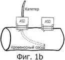
Фиг.1б: хирургическое ввинчиваемое устройство в стенке;Figb: surgical screw-in device in the wall;
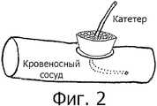
Фиг.2: хирургическое ввинчиваемое устройство, заполненное тромбостатическим или кровоостанавливающим веществом;Figure 2: a surgical screw-in device filled with a thrombostatic or hemostatic substance;
Фиг.3а: хирургическое ввинчиваемое устройство со съемной головкой, вид сбоку;Figa: surgical screw-in device with a removable head, side view;
Фиг.3б: хирургическое ввинчиваемое устройство со съемной головкой, вид сверху;Figb: surgical screw-in device with a removable head, top view;
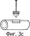
Фиг.3в: с хирургическое ввинчиваемое устройство со съемной головкой, расположение в стенке;Figv: with a surgical screw-in device with a removable head, the location in the wall;
Фиг.3г: хирургическое ввинчиваемое устройство со съемной головкой, обзор способа, в соответствии с которым съемная головка присоединена к хирургическому ввинчиваемому устройству.Fig. 3g: a surgical screw-in device with a removable head, an overview of the method in which the removable head is connected to a surgical screw-in device.
Описание изобретенияDescription of the invention
Изобретение дает возможность просто и быстро закрепить полую структуру, такую как кровеносный сосуд. Более конкретно, позволяет врачу, осуществляющему медицинское вмешательство, обеспечить прочное и безопасное соединение с полой структурой таким образом, чтобы катетер мог быть надежно зафиксирован без какой-либо необходимости в пришивании, отнимающем много времени.The invention makes it possible to simply and quickly fix a hollow structure such as a blood vessel. More specifically, it allows the physician performing the medical intervention to provide a strong and secure connection to the hollow structure so that the catheter can be securely fixed without any need for time-consuming suturing.
Хирургическое ввинчиваемое устройство имеет форму полого винта, на конце которого не острие, как в обычном винте, а один полный спиральный виток (360 градусов). Конец витка острый и закругленный, то есть он нережущий, но способен к перфорированию стенки полой структуры трубочного типа, в которую он ввинчивается. Острое закругленное окончание отогнуто внутрь и вниз под углом от 10 до 20 градусов (α) (см. фиг.1а). Альтернативно, это острое, закругленное, нережущее окончание может отгибаться вниз под углом 90 градусов (α) (см. фиг.1б). В этом случае конец имеет сходство со штопором, но конец расположен не в середине последнего витка, а на периферии.The screw-in surgical device has the form of a hollow screw, on the end of which is not a sharp point, as in a conventional screw, but one full spiral turn (360 degrees). The end of the turn is sharp and rounded, that is, it is non-cutting, but capable of perforating the walls of the hollow structure of the tube type into which it is screwed. The sharp rounded end is bent inward and downward at an angle of 10 to 20 degrees (α) (see figa). Alternatively, this sharp, rounded, non-cutting ending may bend downward at an angle of 90 degrees (α) (see FIG. 1 b). In this case, the end resembles a corkscrew, but the end is not located in the middle of the last turn, but on the periphery.
Хирургическое ввинчиваемое устройство такое же как упоминалось выше, но внутренняя часть которого заполнена тромбостатическим или кровоостанавливающим веществом, которые функционируют как губка при подтекании сосуда после того, как катетер был удален (см. фиг.2).The screw-in surgical device is the same as mentioned above, but the inside of which is filled with a thrombostatic or hemostatic substance that functions like a sponge when the vessel leaks after the catheter has been removed (see FIG. 2).
Хирургическое ввинчиваемое устройство со съемной головкой. Это устройство состоит из двух основных частей: первая - это съемная головка с аппликатором (то есть длинным, тонким стержнем с ручкой, используемым для вкручивания головки в стенку сосуда) и вторая - полое внутри с полым винтом с тремя витками, которое остается на месте (то есть в стенке сосуда).The surgical screw-in device with a removable head. This device consists of two main parts: the first is a removable head with an applicator (that is, a long, thin rod with a handle used to screw the head into the vessel wall) and the second is a hollow inside with a hollow screw with three turns that remains in place ( that is, in the wall of the vessel).
Съемная головка включает два витка и концы в форме штопора (см. фиг.3а, 3б). Это опять закругленное, острое, нережущее окончание. Головка образует единое целое с аппликатором. Как только головка встает на место (то есть в центр стенки сосуда) (см. фиг.3в), ее удаляют вместе с аппликатором от оставшейся части устройства, которая остается внутри стенки сосуда.The removable head includes two turns and ends in the form of a corkscrew (see figa, 3b). This is again a rounded, sharp, non-cutting ending. The head forms a single unit with the applicator. As soon as the head snaps into place (i.e., in the center of the vessel wall) (see FIG. 3c), it is removed together with the applicator from the remaining part of the device that remains inside the vessel wall.
Вторая составляющая - это центральная часть устройства. Она состоит из трех полых витков, присоединенных к головке с помощью внутренних витков, закрученных против часовой стрелки (см. фиг.3г). Каждый следующий виток шире предыдущего, что, соответственно, раздвигает стенку сосуда. Отверстие в стенке проделывается головкой неокклюзионным способом, то есть нет необходимости временно пережимать рецепторный сосуд.The second component is the central part of the device. It consists of three hollow turns attached to the head by means of internal turns twisted counterclockwise (see Fig. 3d). Each subsequent turn is wider than the previous one, which, accordingly, pushes the vessel wall. The hole in the wall is made by the head in a non-occlusive manner, that is, there is no need to temporarily pinch the receptor vessel.
В зависимости от вида полой структуры, такой как кровеносный сосуд, диаметр устройства может варьировать от 1 миллиметра до 2 сантиметров и даже более.Depending on the type of hollow structure, such as a blood vessel, the diameter of the device can vary from 1 millimeter to 2 centimeters or more.
Устройство производится из неокисляемого материала или титана, или из суперэластичных материалов, таких как нитинол, или синтетических материалов, или даже рассасывающихся материалов.The device is made from non-oxidizable material or titanium, or from superelastic materials such as nitinol, or synthetic materials, or even absorbable materials.
В зависимости от диаметра кровеносного сосуда, толщина материала может варьировать от 0,1 мм до любой требуемой толщины. Эластичность зависит от материала.Depending on the diameter of the blood vessel, the thickness of the material can vary from 0.1 mm to any desired thickness. Elasticity depends on the material.
Применение устройстваDevice application
Хирургическое устройство ввинчивают на один оборот в 360 градусов в стенку рецептора. Это обеспечивает прочную фиксацию на стенке. Затем через стенку устройства вводят иглу или катетер и закрепляют таким образом, что они не могут выскользнуть из сосуда или перемещаться по сосуду.The surgical device is screwed 360 degrees into the receptor wall. This provides a solid hold on the wall. Then, a needle or catheter is inserted through the wall of the device and fixed so that they cannot slip out of the vessel or move along the vessel.
При применении данного изобретения хирург сразу прибегает к помощи ввинчиваемого устройства, делает только очень небольшое отверстие передним витком и затем может уже ввинчивать ввинчиваемое устройство в стенку структуры трубочного типа, при этом не происходит утечки жидкости из структуры трубочного типа, так как перфорация закрывается последующими витками. Если требуется выполнить отверстие в центральном канале пустотелого ввинчиваемого устройства, такое отверстие делается только после установки, когда ввинчиваемое устройство уже плотно установлено на стенке.When applying this invention, the surgeon immediately resortes to the help of a screw-in device, makes only a very small hole in the front turn, and then can screw the screw-in device into the wall of the tube-type structure, without leakage of fluid from the tube-type structure, since the perforation is closed by subsequent turns. If you want to make a hole in the Central channel of the hollow screw-in device, such a hole is made only after installation, when the screw-in device is already tightly mounted on the wall.
Изготовление и промышленное применениеManufacturing and Industrial Applications
Ввинчиваемое устройство может быть изготовлено в промышленном масштабе и использовано для анастомоза двух сосудов различного или одинакового размера. Оно может применяться во всех областях сосудистой хирургии, сердечной хирургии и нейрохирургии.The screw-in device can be manufactured on an industrial scale and used for anastomosis of two vessels of different or the same size. It can be used in all areas of vascular surgery, cardiac surgery and neurosurgery.
Claims (8)
Translated fromRussianApplications Claiming Priority (2)
| Application Number | Priority Date | Filing Date | Title |
|---|---|---|---|
| BE0300074 | 2003-04-28 | ||
| BEPCT/BE03/00074 | 2003-04-28 |
Publications (2)
| Publication Number | Publication Date |
|---|---|
| RU2005136882A RU2005136882A (en) | 2006-05-10 |
| RU2359715C2true RU2359715C2 (en) | 2009-06-27 |
Family
ID=33315066
Family Applications (2)
| Application Number | Title | Priority Date | Filing Date |
|---|---|---|---|
| RU2005136882/14ARU2359715C2 (en) | 2003-04-28 | 2003-07-07 | Surgical screwed in device |
| RU2005136883/14ARU2329774C2 (en) | 2003-04-28 | 2003-07-22 | Screw anastomosis device |
Family Applications After (1)
| Application Number | Title | Priority Date | Filing Date |
|---|---|---|---|
| RU2005136883/14ARU2329774C2 (en) | 2003-04-28 | 2003-07-22 | Screw anastomosis device |
Country Status (13)
| Country | Link |
|---|---|
| US (6) | US20060122638A1 (en) |
| EP (2) | EP1628702B1 (en) |
| JP (2) | JP4560412B2 (en) |
| CN (2) | CN100506309C (en) |
| AU (2) | AU2003257278B2 (en) |
| CA (2) | CA2523871C (en) |
| CY (2) | CY1116549T1 (en) |
| DK (2) | DK1628702T3 (en) |
| ES (2) | ES2423514T3 (en) |
| PT (2) | PT1628702E (en) |
| RU (2) | RU2359715C2 (en) |
| SI (2) | SI1628702T1 (en) |
| WO (2) | WO2004096337A1 (en) |
Families Citing this family (44)
| Publication number | Priority date | Publication date | Assignee | Title |
|---|---|---|---|---|
| US9101765B2 (en) | 1999-03-05 | 2015-08-11 | Metacure Limited | Non-immediate effects of therapy |
| US6600953B2 (en) | 2000-12-11 | 2003-07-29 | Impulse Dynamics N.V. | Acute and chronic electrical signal therapy for obesity |
| JP4246492B2 (en) | 2001-01-05 | 2009-04-02 | メタキュアー ナームロゼ フェンノートシャップ | Regulation of eating habits |
| EP1628702B1 (en)* | 2003-04-28 | 2013-05-01 | Erwin De Winter | Anchoring screw device |
| JP4943841B2 (en) | 2003-06-20 | 2012-05-30 | メタキュアー リミティド | Gastrointestinal methods and devices for use in treating disorders |
| US7618427B2 (en) | 2003-12-29 | 2009-11-17 | Ethicon Endo-Surgery, Inc. | Device and method for intralumenal anastomosis |
| US9138228B2 (en) | 2004-08-11 | 2015-09-22 | Emory University | Vascular conduit device and system for implanting |
| GB0419954D0 (en) | 2004-09-08 | 2004-10-13 | Advotek Medical Devices Ltd | System for directing therapy |
| US9821158B2 (en) | 2005-02-17 | 2017-11-21 | Metacure Limited | Non-immediate effects of therapy |
| US8894661B2 (en) | 2007-08-16 | 2014-11-25 | Smith & Nephew, Inc. | Helicoil interference fixation system for attaching a graft ligament to a bone |
| US20080154314A1 (en)* | 2006-08-16 | 2008-06-26 | Mcdevitt Dennis M | Composite interference screw for attaching a graft ligament to a bone, and other apparatus for making attachments to bone |
| US8777971B2 (en)* | 2006-10-17 | 2014-07-15 | Amj Bv | Device and method for joining vessels in anastomosis |
| US7846123B2 (en) | 2007-04-24 | 2010-12-07 | Emory University | Conduit device and system for implanting a conduit device in a tissue wall |
| JP5587892B2 (en)* | 2008-10-28 | 2014-09-10 | コーニンクレッカ フィリップス エヌ ヴェ | Further use of screw threads |
| US8905961B2 (en)* | 2008-12-19 | 2014-12-09 | St. Jude Medical, Inc. | Systems, apparatuses, and methods for cardiovascular conduits and connectors |
| US9682180B2 (en) | 2009-11-15 | 2017-06-20 | Thoratec Corporation | Attachment system, device and method |
| US8934975B2 (en) | 2010-02-01 | 2015-01-13 | Metacure Limited | Gastrointestinal electrical therapy |
| US9308080B2 (en) | 2010-03-10 | 2016-04-12 | Smith & Nephew Inc. | Composite interference screws and drivers |
| US9775702B2 (en) | 2010-03-10 | 2017-10-03 | Smith & Nephew, Inc. | Composite interference screws and drivers |
| US8979865B2 (en) | 2010-03-10 | 2015-03-17 | Smith & Nephew, Inc. | Composite interference screws and drivers |
| US9579188B2 (en) | 2010-03-10 | 2017-02-28 | Smith & Nephew, Inc. | Anchor having a controlled driver orientation |
| WO2012036914A1 (en) | 2010-09-15 | 2012-03-22 | Icecure Medical Ltd. | Cryosurgical instrument for treating large volume of tissue |
| RU2452401C2 (en)* | 2010-11-30 | 2012-06-10 | Федеральное государственное учреждение "Московский научно-исследовательский онкологический институт им. П.А. Герцена" Министерства здравоохранения и социального развития РФ (ФГУ "МНИОИ им. П.А. Герцена" Минздравсоцразвития РФ) | Method of microvascular anastomosis formation |
| WO2012096563A1 (en)* | 2011-01-12 | 2012-07-19 | Amj B.V. | Side to side anastomosis |
| JP6130302B2 (en) | 2011-01-28 | 2017-05-17 | アピカ カーディオヴァスキュラー リミテッド | System for sealing tissue wall stings |
| WO2012106422A2 (en) | 2011-02-01 | 2012-08-09 | Georgia Tech Research Corporation | Systems for implanting and using a conduit within a tissue wall |
| WO2012116376A1 (en) | 2011-02-25 | 2012-08-30 | Thoratec Corporation | Coupling system, applicator tool, attachment ring and method for connecting a conduit to biological tissue |
| MX344606B (en) | 2011-03-11 | 2016-12-20 | Smith & Nephew Inc | Trephine. |
| WO2012158919A2 (en) | 2011-05-18 | 2012-11-22 | Thoratec Corporation | Coring knife |
| AU2012267924B2 (en) | 2011-06-07 | 2016-08-11 | Smith & Nephew, Inc. | Surgical anchor delivery system |
| WO2013162741A1 (en) | 2012-04-23 | 2013-10-31 | Thoratec Corporation | Engagement device and method for deployment of anastomotic clips |
| RU2506910C1 (en)* | 2012-08-01 | 2014-02-20 | Федеральное государственное бюджетное образовательное учреждение высшего профессионального образования "Санкт-Петербургский государственный университет" (СПбГУ) | Disposable arteriotome for carrying out non-occlusive vascular anastomosis |
| EP2948104B1 (en) | 2013-01-25 | 2019-07-24 | Apica Cardiovascular Limited | Systems for percutaneous access, stabilization and closure of organs |
| EP2968717A4 (en) | 2013-03-15 | 2017-02-22 | Apk Advanced Medical Technologies, Inc. | Devices, systems, and methods for implanting and using a connnector in a tissue wall |
| US9155531B2 (en) | 2013-03-15 | 2015-10-13 | Smith & Nephew, Inc. | Miniaturized dual drive open architecture suture anchor |
| WO2014169058A1 (en) | 2013-04-09 | 2014-10-16 | Smith & Nephew, Inc | Open-architecture interference screw |
| US9545263B2 (en) | 2014-06-19 | 2017-01-17 | Limflow Gmbh | Devices and methods for treating lower extremity vasculature |
| US10485909B2 (en) | 2014-10-31 | 2019-11-26 | Thoratec Corporation | Apical connectors and instruments for use in a heart wall |
| US11344329B2 (en) | 2015-06-26 | 2022-05-31 | Scott & White Healthcare | Vascular graft securement apparatuses and related kits and methods |
| PL3338610T3 (en) | 2016-12-23 | 2020-07-27 | Eurofilters Holding N.V. | Holding plate for vacuum cleaner bag having seal |
| EP3609415B1 (en) | 2017-04-10 | 2023-08-23 | LimFlow GmbH | Devices for treating lower extremity vasculature |
| SG11202102500UA (en) | 2018-10-09 | 2021-04-29 | Limflow Gmbh | Devices and methods for catheter alignment |
| US12114858B2 (en) | 2019-05-07 | 2024-10-15 | Easyflomicro Inc. | Apparatuses for anastomosis of tubular vessels and related methods |
| EP4051174A4 (en) | 2019-11-01 | 2023-11-22 | LimFlow GmbH | Devices and methods for increasing blood perfusion to a distal extremity |
Citations (6)
| Publication number | Priority date | Publication date | Assignee | Title |
|---|---|---|---|---|
| RU2078588C1 (en)* | 1992-12-21 | 1997-05-10 | Александр Вадимович Никонов | Multipurpose apparatus for selective remote-controlled catheterization of blood vessels |
| US5671773A (en)* | 1995-11-09 | 1997-09-30 | Daewoo Electronics Co, Ltd. | Automatic fluid-supply apparatus for a boiler system |
| US5755697A (en)* | 1995-11-22 | 1998-05-26 | Jones; Calvin E. | Self-tunneling, self-securing percutaneous catheterization device and method of use thereof |
| US5891100A (en)* | 1995-01-25 | 1999-04-06 | Fleckenstein; Wolfgang | Securing device for brain scan probes |
| DE19826078C1 (en)* | 1998-06-12 | 1999-08-19 | Gms | Brain measurement probe assembly |
| US6210397B1 (en)* | 1999-01-13 | 2001-04-03 | A-Med Systems, Inc. | Sealing cannula device |
Family Cites Families (29)
| Publication number | Priority date | Publication date | Assignee | Title |
|---|---|---|---|---|
| US3683891A (en)* | 1970-06-26 | 1972-08-15 | Marshall Eskridge | Tissue auger |
| US4595007A (en)* | 1983-03-14 | 1986-06-17 | Ethicon, Inc. | Split ring type tissue fastener |
| US4495007A (en) | 1984-03-12 | 1985-01-22 | At&T Technologies, Inc. | Soldering flux |
| US4762453A (en)* | 1986-01-29 | 1988-08-09 | Textron, Inc. | Helical coil fastener |
| US6171338B1 (en)* | 1988-11-10 | 2001-01-09 | Biocon, Oy | Biodegradable surgical implants and devices |
| IT1240639B (en)* | 1990-05-04 | 1993-12-17 | Francesco Pianetti | TREQUARTI NEEDLE FOR THREADED-CONICAL POINTED LAPAROSCOPY |
| US5282827A (en)* | 1991-11-08 | 1994-02-01 | Kensey Nash Corporation | Hemostatic puncture closure system and method of use |
| US5163343A (en)* | 1992-02-21 | 1992-11-17 | Gish Donald A | System for fastening plies of fabric |
| US5437266A (en)* | 1992-07-02 | 1995-08-01 | Mcpherson; William | Coil screw surgical retractor |
| CN2158687Y (en)* | 1993-03-26 | 1994-03-16 | 李慎宝 | Gastrointestinal wall punch |
| US5370662A (en)* | 1993-06-23 | 1994-12-06 | Kevin R. Stone | Suture anchor assembly |
| GB9322240D0 (en)* | 1993-10-28 | 1993-12-15 | Microsurgical Equipment Ltd | Improvements in and relating to needle holder jaws |
| US5582616A (en)* | 1994-08-05 | 1996-12-10 | Origin Medsystems, Inc. | Surgical helical fastener with applicator |
| US6132438A (en)* | 1995-06-07 | 2000-10-17 | Ep Technologies, Inc. | Devices for installing stasis reducing means in body tissue |
| US5662683A (en)* | 1995-08-22 | 1997-09-02 | Ortho Helix Limited | Open helical organic tissue anchor and method of facilitating healing |
| US5651773A (en)* | 1996-01-19 | 1997-07-29 | Perry; Larry C. | Skin protector for ultrasonic-assisted liposuction and accessories |
| US5810851A (en)* | 1996-03-05 | 1998-09-22 | Yoon; Inbae | Suture spring device |
| JP2995651B2 (en)* | 1996-06-17 | 1999-12-27 | 信一 小野原 | Double injection needle |
| IL119911A (en) | 1996-12-25 | 2001-03-19 | Niti Alloys Tech Ltd | Surgical clip |
| EP0937481A1 (en)* | 1998-02-19 | 1999-08-25 | Precision Vascular Systems, Inc. | Catheter or guidewire with varying flexibility |
| US6113611A (en) | 1998-05-28 | 2000-09-05 | Advanced Vascular Technologies, Llc | Surgical fastener and delivery system |
| US6458092B1 (en)* | 1998-09-30 | 2002-10-01 | C. R. Bard, Inc. | Vascular inducing implants |
| US6517519B1 (en)* | 1999-08-13 | 2003-02-11 | The Johns Hopkins University | Device and method for rapid chest tube insertion |
| US6774442B2 (en)* | 2000-07-21 | 2004-08-10 | Renesas Technology Corp. | Semiconductor device and CMOS transistor |
| US6663633B1 (en)* | 2000-10-25 | 2003-12-16 | Pierson, Iii Raymond H. | Helical orthopedic fixation and reduction device, insertion system, and associated methods |
| AU2002353807B2 (en)* | 2001-11-28 | 2008-08-14 | Aptus Endosystems, Inc. | Endovascular aneurysm repair system |
| US6619493B2 (en)* | 2002-01-28 | 2003-09-16 | Heng-Te Yang | Sealable container |
| EP1628702B1 (en)* | 2003-04-28 | 2013-05-01 | Erwin De Winter | Anchoring screw device |
| EP1547526A1 (en)* | 2003-12-23 | 2005-06-29 | UMC Utrecht Holding B.V. | Operation element, operation set and method for use thereof |
- 2003
- 2003-07-07EPEP03816760.7Apatent/EP1628702B1/ennot_activeExpired - Lifetime
- 2003-07-07CACA2523871Apatent/CA2523871C/ennot_activeExpired - Fee Related
- 2003-07-07SISI200332284Tpatent/SI1628702T1/enunknown
- 2003-07-07USUS10/554,947patent/US20060122638A1/ennot_activeAbandoned
- 2003-07-07CNCNB038263777Apatent/CN100506309C/ennot_activeExpired - Fee Related
- 2003-07-07RURU2005136882/14Apatent/RU2359715C2/ennot_activeIP Right Cessation
- 2003-07-07JPJP2004571203Apatent/JP4560412B2/ennot_activeExpired - Fee Related
- 2003-07-07ESES03816760Tpatent/ES2423514T3/ennot_activeExpired - Lifetime
- 2003-07-07PTPT38167607Tpatent/PT1628702E/enunknown
- 2003-07-07DKDK03816760.7Tpatent/DK1628702T3/enactive
- 2003-07-07AUAU2003257278Apatent/AU2003257278B2/ennot_activeCeased
- 2003-07-07WOPCT/BE2003/000120patent/WO2004096337A1/enactiveApplication Filing
- 2003-07-22PTPT38167615Tpatent/PT1628582E/enunknown
- 2003-07-22SISI200332424Tpatent/SI1628582T1/enunknown
- 2003-07-22CACA2523803Apatent/CA2523803C/ennot_activeExpired - Fee Related
- 2003-07-22JPJP2004571204Apatent/JP4428567B2/ennot_activeExpired - Fee Related
- 2003-07-22ESES03816761.5Tpatent/ES2535485T3/ennot_activeExpired - Lifetime
- 2003-07-22WOPCT/BE2003/000126patent/WO2004096059A1/enactiveApplication Filing
- 2003-07-22AUAU2003254421Apatent/AU2003254421B2/ennot_activeCeased
- 2003-07-22DKDK03816761Tpatent/DK1628582T3/enactive
- 2003-07-22EPEP03816761.5Apatent/EP1628582B1/ennot_activeExpired - Lifetime
- 2003-07-22USUS10/554,986patent/US7749239B2/ennot_activeExpired - Lifetime
- 2003-07-22RURU2005136883/14Apatent/RU2329774C2/ennot_activeIP Right Cessation
- 2003-07-22CNCN038265451Apatent/CN1771011B/ennot_activeExpired - Fee Related
- 2005
- 2005-10-28USUS11/262,525patent/US20060241659A1/ennot_activeAbandoned
- 2005-10-28USUS11/262,290patent/US20060253080A1/ennot_activeAbandoned
- 2009
- 2009-09-09USUS12/556,114patent/US8795299B2/ennot_activeExpired - Lifetime
- 2013
- 2013-07-31CYCY20131100652Tpatent/CY1116549T1/enunknown
- 2014
- 2014-01-23USUS14/161,907patent/US20140188049A1/ennot_activeAbandoned
- 2015
- 2015-04-27CYCY20151100387Tpatent/CY1116322T1/enunknown
Patent Citations (6)
| Publication number | Priority date | Publication date | Assignee | Title |
|---|---|---|---|---|
| RU2078588C1 (en)* | 1992-12-21 | 1997-05-10 | Александр Вадимович Никонов | Multipurpose apparatus for selective remote-controlled catheterization of blood vessels |
| US5891100A (en)* | 1995-01-25 | 1999-04-06 | Fleckenstein; Wolfgang | Securing device for brain scan probes |
| US5671773A (en)* | 1995-11-09 | 1997-09-30 | Daewoo Electronics Co, Ltd. | Automatic fluid-supply apparatus for a boiler system |
| US5755697A (en)* | 1995-11-22 | 1998-05-26 | Jones; Calvin E. | Self-tunneling, self-securing percutaneous catheterization device and method of use thereof |
| DE19826078C1 (en)* | 1998-06-12 | 1999-08-19 | Gms | Brain measurement probe assembly |
| US6210397B1 (en)* | 1999-01-13 | 2001-04-03 | A-Med Systems, Inc. | Sealing cannula device |
Also Published As
Similar Documents
| Publication | Publication Date | Title |
|---|---|---|
| RU2359715C2 (en) | Surgical screwed in device | |
| US5460170A (en) | Adjustable surgical retractor | |
| US3540451A (en) | Drainage cannula with tissue connecting assemblies on both ends | |
| US5810884A (en) | Apparatus and method for closing a vascular perforation after percutaneous puncture of a blood vessel in a living subject | |
| AU2002249775B2 (en) | System and method for establishing vascular access | |
| US12263320B2 (en) | Percutaneous access pathway system and method | |
| US8974493B2 (en) | Method and apparatus for sealing access | |
| WO2011102988A1 (en) | Anatomic needle system | |
| JP2008546486A (en) | Expandable surgical site access system | |
| US20120130507A1 (en) | Permanent umbilical hollow tube | |
| JP2006006648A (en) | Blood vessel connecting tool and blood vessel connecting device | |
| RU2420243C1 (en) | Method of treating bone cysts and device for its realisation | |
| RU44511U1 (en) | DEVICE FOR ENDOVASCULAR OPERATIONS | |
| RU2804218C1 (en) | Method for fixing catheter in vessel by creating skin roll around cannula | |
| RU2199962C2 (en) | Device for temporally reducing blood circulation and draining the abdominal cavity when performing surgical operations on spleen | |
| RU2218190C1 (en) | Draining tube for draining common hepatic duct in performing laparoscopic cholecystectomy and method for fixing the tube in the cystic duct | |
| RU2007134C1 (en) | Agraffe for treating deep stabbed-incised wounds of parenchymatous organs | |
| RU2607155C1 (en) | Method of cannulation of peripheral lymphatic vessels for obtaining of lymph | |
| JP2006006649A (en) | Blood vessel connecting tool and blood vessel connecting device | |
| UA61772A (en) | Method for catheterizing arteries in surgical treatment of spondylitis |
Legal Events
| Date | Code | Title | Description |
|---|---|---|---|
| MM4A | The patent is invalid due to non-payment of fees | Effective date:20160708 |