RU2352685C2 - Simple system of chemical deposition from vapours and plating methods of many-metallic aluminide coatings - Google Patents
Simple system of chemical deposition from vapours and plating methods of many-metallic aluminide coatingsDownload PDFInfo
- Publication number
- RU2352685C2 RU2352685C2RU2005141760/02ARU2005141760ARU2352685C2RU 2352685 C2RU2352685 C2RU 2352685C2RU 2005141760/02 ARU2005141760/02 ARU 2005141760/02ARU 2005141760 ARU2005141760 ARU 2005141760ARU 2352685 C2RU2352685 C2RU 2352685C2
- Authority
- RU
- Russia
- Prior art keywords
- reaction chamber
- container
- vapor
- main reaction
- phase reagent
- Prior art date
Links
Images

Classifications
- C—CHEMISTRY; METALLURGY
- C23—COATING METALLIC MATERIAL; COATING MATERIAL WITH METALLIC MATERIAL; CHEMICAL SURFACE TREATMENT; DIFFUSION TREATMENT OF METALLIC MATERIAL; COATING BY VACUUM EVAPORATION, BY SPUTTERING, BY ION IMPLANTATION OR BY CHEMICAL VAPOUR DEPOSITION, IN GENERAL; INHIBITING CORROSION OF METALLIC MATERIAL OR INCRUSTATION IN GENERAL
- C23C—COATING METALLIC MATERIAL; COATING MATERIAL WITH METALLIC MATERIAL; SURFACE TREATMENT OF METALLIC MATERIAL BY DIFFUSION INTO THE SURFACE, BY CHEMICAL CONVERSION OR SUBSTITUTION; COATING BY VACUUM EVAPORATION, BY SPUTTERING, BY ION IMPLANTATION OR BY CHEMICAL VAPOUR DEPOSITION, IN GENERAL
- C23C16/00—Chemical coating by decomposition of gaseous compounds, without leaving reaction products of surface material in the coating, i.e. chemical vapour deposition [CVD] processes
- C23C16/02—Pretreatment of the material to be coated
- C23C16/0272—Deposition of sub-layers, e.g. to promote the adhesion of the main coating
- C23C16/029—Graded interfaces
- C—CHEMISTRY; METALLURGY
- C23—COATING METALLIC MATERIAL; COATING MATERIAL WITH METALLIC MATERIAL; CHEMICAL SURFACE TREATMENT; DIFFUSION TREATMENT OF METALLIC MATERIAL; COATING BY VACUUM EVAPORATION, BY SPUTTERING, BY ION IMPLANTATION OR BY CHEMICAL VAPOUR DEPOSITION, IN GENERAL; INHIBITING CORROSION OF METALLIC MATERIAL OR INCRUSTATION IN GENERAL
- C23C—COATING METALLIC MATERIAL; COATING MATERIAL WITH METALLIC MATERIAL; SURFACE TREATMENT OF METALLIC MATERIAL BY DIFFUSION INTO THE SURFACE, BY CHEMICAL CONVERSION OR SUBSTITUTION; COATING BY VACUUM EVAPORATION, BY SPUTTERING, BY ION IMPLANTATION OR BY CHEMICAL VAPOUR DEPOSITION, IN GENERAL
- C23C16/00—Chemical coating by decomposition of gaseous compounds, without leaving reaction products of surface material in the coating, i.e. chemical vapour deposition [CVD] processes
- C23C16/06—Chemical coating by decomposition of gaseous compounds, without leaving reaction products of surface material in the coating, i.e. chemical vapour deposition [CVD] processes characterised by the deposition of metallic material
- C23C16/08—Chemical coating by decomposition of gaseous compounds, without leaving reaction products of surface material in the coating, i.e. chemical vapour deposition [CVD] processes characterised by the deposition of metallic material from metal halides
- C—CHEMISTRY; METALLURGY
- C23—COATING METALLIC MATERIAL; COATING MATERIAL WITH METALLIC MATERIAL; CHEMICAL SURFACE TREATMENT; DIFFUSION TREATMENT OF METALLIC MATERIAL; COATING BY VACUUM EVAPORATION, BY SPUTTERING, BY ION IMPLANTATION OR BY CHEMICAL VAPOUR DEPOSITION, IN GENERAL; INHIBITING CORROSION OF METALLIC MATERIAL OR INCRUSTATION IN GENERAL
- C23C—COATING METALLIC MATERIAL; COATING MATERIAL WITH METALLIC MATERIAL; SURFACE TREATMENT OF METALLIC MATERIAL BY DIFFUSION INTO THE SURFACE, BY CHEMICAL CONVERSION OR SUBSTITUTION; COATING BY VACUUM EVAPORATION, BY SPUTTERING, BY ION IMPLANTATION OR BY CHEMICAL VAPOUR DEPOSITION, IN GENERAL
- C23C16/00—Chemical coating by decomposition of gaseous compounds, without leaving reaction products of surface material in the coating, i.e. chemical vapour deposition [CVD] processes
- C23C16/44—Chemical coating by decomposition of gaseous compounds, without leaving reaction products of surface material in the coating, i.e. chemical vapour deposition [CVD] processes characterised by the method of coating
- C23C16/448—Chemical coating by decomposition of gaseous compounds, without leaving reaction products of surface material in the coating, i.e. chemical vapour deposition [CVD] processes characterised by the method of coating characterised by the method used for generating reactive gas streams, e.g. by evaporation or sublimation of precursor materials
- C23C16/4485—Chemical coating by decomposition of gaseous compounds, without leaving reaction products of surface material in the coating, i.e. chemical vapour deposition [CVD] processes characterised by the method of coating characterised by the method used for generating reactive gas streams, e.g. by evaporation or sublimation of precursor materials by evaporation without using carrier gas in contact with the source material
- C—CHEMISTRY; METALLURGY
- C23—COATING METALLIC MATERIAL; COATING MATERIAL WITH METALLIC MATERIAL; CHEMICAL SURFACE TREATMENT; DIFFUSION TREATMENT OF METALLIC MATERIAL; COATING BY VACUUM EVAPORATION, BY SPUTTERING, BY ION IMPLANTATION OR BY CHEMICAL VAPOUR DEPOSITION, IN GENERAL; INHIBITING CORROSION OF METALLIC MATERIAL OR INCRUSTATION IN GENERAL
- C23C—COATING METALLIC MATERIAL; COATING MATERIAL WITH METALLIC MATERIAL; SURFACE TREATMENT OF METALLIC MATERIAL BY DIFFUSION INTO THE SURFACE, BY CHEMICAL CONVERSION OR SUBSTITUTION; COATING BY VACUUM EVAPORATION, BY SPUTTERING, BY ION IMPLANTATION OR BY CHEMICAL VAPOUR DEPOSITION, IN GENERAL
- C23C16/00—Chemical coating by decomposition of gaseous compounds, without leaving reaction products of surface material in the coating, i.e. chemical vapour deposition [CVD] processes
- C23C16/44—Chemical coating by decomposition of gaseous compounds, without leaving reaction products of surface material in the coating, i.e. chemical vapour deposition [CVD] processes characterised by the method of coating
- C23C16/448—Chemical coating by decomposition of gaseous compounds, without leaving reaction products of surface material in the coating, i.e. chemical vapour deposition [CVD] processes characterised by the method of coating characterised by the method used for generating reactive gas streams, e.g. by evaporation or sublimation of precursor materials
- C23C16/4488—Chemical coating by decomposition of gaseous compounds, without leaving reaction products of surface material in the coating, i.e. chemical vapour deposition [CVD] processes characterised by the method of coating characterised by the method used for generating reactive gas streams, e.g. by evaporation or sublimation of precursor materials by in situ generation of reactive gas by chemical or electrochemical reaction
- C—CHEMISTRY; METALLURGY
- C23—COATING METALLIC MATERIAL; COATING MATERIAL WITH METALLIC MATERIAL; CHEMICAL SURFACE TREATMENT; DIFFUSION TREATMENT OF METALLIC MATERIAL; COATING BY VACUUM EVAPORATION, BY SPUTTERING, BY ION IMPLANTATION OR BY CHEMICAL VAPOUR DEPOSITION, IN GENERAL; INHIBITING CORROSION OF METALLIC MATERIAL OR INCRUSTATION IN GENERAL
- C23C—COATING METALLIC MATERIAL; COATING MATERIAL WITH METALLIC MATERIAL; SURFACE TREATMENT OF METALLIC MATERIAL BY DIFFUSION INTO THE SURFACE, BY CHEMICAL CONVERSION OR SUBSTITUTION; COATING BY VACUUM EVAPORATION, BY SPUTTERING, BY ION IMPLANTATION OR BY CHEMICAL VAPOUR DEPOSITION, IN GENERAL
- C23C28/00—Coating for obtaining at least two superposed coatings either by methods not provided for in a single one of groups C23C2/00 - C23C26/00 or by combinations of methods provided for in subclasses C23C and C25C or C25D
- C23C28/30—Coatings combining at least one metallic layer and at least one inorganic non-metallic layer
- C23C28/32—Coatings combining at least one metallic layer and at least one inorganic non-metallic layer including at least one pure metallic layer
- C23C28/321—Coatings combining at least one metallic layer and at least one inorganic non-metallic layer including at least one pure metallic layer with at least one metal alloy layer
- C23C28/3215—Coatings combining at least one metallic layer and at least one inorganic non-metallic layer including at least one pure metallic layer with at least one metal alloy layer at least one MCrAlX layer
- Y—GENERAL TAGGING OF NEW TECHNOLOGICAL DEVELOPMENTS; GENERAL TAGGING OF CROSS-SECTIONAL TECHNOLOGIES SPANNING OVER SEVERAL SECTIONS OF THE IPC; TECHNICAL SUBJECTS COVERED BY FORMER USPC CROSS-REFERENCE ART COLLECTIONS [XRACs] AND DIGESTS
- Y02—TECHNOLOGIES OR APPLICATIONS FOR MITIGATION OR ADAPTATION AGAINST CLIMATE CHANGE
- Y02T—CLIMATE CHANGE MITIGATION TECHNOLOGIES RELATED TO TRANSPORTATION
- Y02T50/00—Aeronautics or air transport
- Y02T50/60—Efficient propulsion technologies, e.g. for aircraft
Landscapes
- Chemical & Material Sciences (AREA)
- General Chemical & Material Sciences (AREA)
- Chemical Kinetics & Catalysis (AREA)
- Engineering & Computer Science (AREA)
- Materials Engineering (AREA)
- Mechanical Engineering (AREA)
- Metallurgy (AREA)
- Organic Chemistry (AREA)
- Electrochemistry (AREA)
- Chemical Vapour Deposition (AREA)
- Crystals, And After-Treatments Of Crystals (AREA)
Abstract
Description
Translated fromRussianПерекрестная ссылка на родственные заявкиCross reference to related applications
Эта заявка относится к заявке с порядковым №09/439210, поданной 12 ноября 1999 г.This application relates to the application with serial number 09/439210, filed November 12, 1999
Область применения изобретенияThe scope of the invention
Изобретение относится к простой системе химического осаждения из паров и, в частности, к простой системе химического осаждения из паров, оснащенной для создания защитного слоя на деталях реактивного двигателя.The invention relates to a simple chemical vapor deposition system and, in particular, to a simple chemical vapor deposition system equipped to create a protective layer on the details of a jet engine.
Предпосылки к созданию изобретенияBACKGROUND OF THE INVENTION
Детали реактивного двигателя, изготовленные из сверхпрочного сплава, подвергаются воздействию экстремальных рабочих условий, которые могут оказать вредное влияние на их поверхность. Для защиты поверхности на нее наносят жертвенный интерметаллический слой для образования защитного оксидного слоя, в то время как деталь реактивного двигателя находится в эксплуатации. После того как жертвенный интерметаллический слой изнашивается и становится тонким во время использования, удаляют этот слой и наносят новый жертвенный интерметаллический слой. Этот процесс повторяют максимально возможное количество раз, чтобы продлить срок службы детали реактивного двигателя.Jet engine parts made of heavy-duty alloy are exposed to extreme operating conditions that can have a harmful effect on their surface. To protect the surface, a sacrificial intermetallic layer is applied on it to form a protective oxide layer, while the jet engine part is in operation. After the sacrificial intermetallic layer wears out and becomes thin during use, this layer is removed and a new sacrificial intermetallic layer is applied. This process is repeated as many times as possible in order to extend the life of the jet engine part.
Интерметаллический слой обычно образуют простым способом химического осаждения из паров (ХОП), при котором очищенную деталь реактивного двигателя подвергают воздействию обедненной кислородом среды в реакционной камере. Внутри реакционной камеры обычно находятся материал-активатор и материал-донор, содержащий, по меньшей мере, один металл, вводимый в интерметаллический слой. Реакционную камеру продувают атмосферными газами и вакуумируют. Материал-активатор и материал-донор нагревают для образования парофазных реагентов, которые вызывают перенос металла из материала-донора к детали реактивного двигателя. Интерметаллический слой, образованный на детали реактивного двигателя, может содержать собственный металл, диффундированный наружу из сплава, образующего деталь реактивного двигателя. Однако интерметаллический слой может также содержать, по меньшей мере, один примесный металл из материала-донора.The intermetallic layer is usually formed by a simple chemical vapor deposition (CVD) method in which a cleaned jet engine part is exposed to an oxygen-depleted medium in the reaction chamber. Inside the reaction chamber are usually an activator material and a donor material containing at least one metal introduced into the intermetallic layer. The reaction chamber is purged with atmospheric gases and vacuum. The activator material and the donor material are heated to form vapor-phase reagents, which cause the transfer of metal from the donor material to the details of the jet engine. The intermetallic layer formed on the jet engine part may comprise intrinsic metal diffused outwardly from the alloy forming the jet engine part. However, the intermetallic layer may also contain at least one impurity metal from the donor material.
Наиболее распространенным примесным металлом, используемым в интерметаллическом слое, является алюминий. С этой целью типичные материалы-доноры содержат алюминий, так что алюминий образует большую часть интерметаллического слоя. Однако желательно, чтобы в интерметаллическом слое в значительной концентрации присутствовал также второй примесный металл. Современные способы введения второго примесного металла в интерметаллический слой являются дорогостоящими и громоздкими и часто приводят к менее желательным интерметаллическим слоям.The most common impurity metal used in the intermetallic layer is aluminum. To this end, typical donor materials contain aluminum, so that aluminum forms a large part of the intermetallic layer. However, it is desirable that a second impurity metal is also present in a significant concentration in the intermetallic layer. Current methods for introducing a second impurity metal into the intermetallic layer are expensive and cumbersome and often lead to less desirable intermetallic layers.
Например, обычный материал-донор может представлять собой порошок или мелкие куски хромоалюминиевого сплава, в котором хром присутствует для повышения температуры плавления материала. Как полагают, во время процесса ХОП хром фактически или почти не будет переноситься от материала-донора к детали реактивного двигателя, и даже если хром достигает детали реактивного двигателя, он может неоднородным образом встраиваться в интерметаллический слой. Действительно, так как алюминий является более химически активным, чем хром, то хром из материала-донора не может в значительной концентрации быть введен в интерметаллический слой, пока не исчерпается алюминий из материала-донора. Результатом могут быть интерметаллические слои, отличающиеся плохими свойствами и/или чрезмерно длительной продолжительностью производственного цикла. В определенных случаях применения невозможность выделения хрома из материала-донора может препятствовать достижению полезных результатов, обусловленных присутствием хрома в покрытии, образующемся на детали реактивного двигателя.For example, a conventional donor material may be a powder or small pieces of a chromium-aluminum alloy in which chromium is present to increase the melting point of the material. It is believed that during the CVD process, chromium will practically or almost not be transferred from the donor material to the jet engine part, and even if chromium reaches the jet engine part, it can be inhomogeneously integrated into the intermetallic layer. Indeed, since aluminum is more chemically active than chromium, chromium from the donor material cannot be introduced into the intermetallic layer in significant concentration until aluminum is exhausted from the donor material. The result can be intermetallic layers characterized by poor properties and / or an excessively long production cycle. In certain applications, the impossibility of separating chromium from a donor material can impede the achievement of beneficial results due to the presence of chromium in the coating formed on the details of the jet engine.
Другие подходы к введению двух примесных металлов в интерметаллический слой страдают сопоставимыми недостатками. Например, предлагалось вначале покрывать деталь реактивного двигателя хромом или платиной, например, нанесением электролитического покрытия до помещения ее в реакционную камеру простой системы ХОП и образования интерметаллического слоя. Хотя результатом этого могут быть интерметаллические слои, содержащие хром или платину и алюминий, происходящий из материала-донора, этот способ длителен и является дорогостоящим, а также требует использования значительно больше хрома или платины, чем это необходимо. Кроме того, электролитические покрытия страдают неоднородностью вследствие естественных тенденций электролитических покрытий иметь большую толщину у острых краев и вблизи их.Other approaches to the introduction of two impurity metals into the intermetallic layer suffer from comparable disadvantages. For example, it was proposed at first to cover a part of a jet engine with chrome or platinum, for example, by applying an electrolytic coating before placing it in the reaction chamber of a simple CVD system and forming an intermetallic layer. Although the result may be intermetallic layers containing chromium or platinum and aluminum originating from the donor material, this method is lengthy and expensive, and also requires the use of much more chromium or platinum than necessary. In addition, electrolytic coatings suffer from heterogeneity due to the natural tendency of electrolytic coatings to have a greater thickness at and near sharp edges.
Таким образом, существует потребность в усовершенствованных устройствах и способе для нанесения алюминидного слоя, имеющего два примесных металла, на детали реактивного двигателя, изготовленные из сверхпрочного сплава, и на другие виды деталей из сверхпрочного сплава.Thus, there is a need for improved devices and a method for applying an aluminide layer having two impurity metals on jet engine parts made of heavy-duty alloy and other types of parts of heavy-duty alloy.
Сущность изобретенияSUMMARY OF THE INVENTION
Согласно настоящему изобретению предлагаются устройство и способ ХОП для образования алюминидного слоя, содержащего два или большее число примесных металлов, на открытой поверхности детали реактивного двигателя, изготовленной из сверхпрочного сплава, при отсутствии недостатков способов и систем, известных из предшествующего уровня техники и направленных на достижение той же самой цели. В соответствии с сущностью настоящего изобретения, второй примесный металл подается из отдельного контейнера, расположенного снаружи реакционной камеры. Наружный контейнер имеет относительно небольшой объем и выполнен с возможностью содержать в себе твердый материал, содержащий второй примесный металл. Контейнер выполнен обогреваемым и герметизированным, за исключением закрытого хода, который допускает пассивное перемещение парофазного реагента от твердого материала, содержащего второй примесный металл, к главной реакционной камере ХОП.According to the present invention, there is provided a device and a method of CVD for forming an aluminide layer containing two or more impurity metals on an open surface of a jet engine part made of heavy-duty alloy, without the disadvantages of the methods and systems known from the prior art and aimed at achieving that same goal. In accordance with the essence of the present invention, the second impurity metal is supplied from a separate container located outside the reaction chamber. The outer container has a relatively small volume and is configured to contain solid material containing a second impurity metal. The container is made heated and sealed, with the exception of the closed passage, which allows passive movement of the vapor-phase reagent from a solid material containing a second impurity metal to the main reaction chamber of the OCP.
Первый примесный металл может быть доставлен обычным образом, например, от мелких кусков в простой реакционной камере ХОП или от доноронесущего газа, вводимого в динамическую реакционную камеру ХОП. Однако в отличие от динамических систем ХОП сам отдельный контейнер пассивно соединен с главной реакционной камерой закрытым ходом, что тем самым исключает какую-либо опору на находящийся под давлением поток коррозионного или инертного газа-носителя в наружный контейнер или через него. Контейнер нагревают до температуры, эффективной для превращения твердого материала, содержащего второй примесный металл, в парофазный реагент, который затем по закрытому ходу мигрирует или диффундирует в главную реакционную камеру. Таким образом, второй примесный металл вводят в главную реакционную камеру уже в паровой фазе, но отдельно от другого примесного металла и без помощи находящегося под давлением потока коррозионного или инертного газа-носителя. Примесные металлы в паровых фазах затем могут химически соединяться у поверхности детали реактивного двигателя для образования интерметаллического слоя с многочисленными металлами, но без больших затрат, производственных потерь и других недостатков, известных из уровня техники для систем и способов, которые направлены на введение многочисленных примесных металлов в интерметаллический слой.The first impurity metal can be delivered in the usual way, for example, from small pieces in a simple CVD reaction chamber or from a donor gas introduced into the dynamic CVD reaction chamber. However, unlike dynamic CVD systems, the separate container itself is passively connected to the main reaction chamber by a closed path, thereby eliminating any reliance on the pressurized flow of corrosive or inert carrier gas into or through the external container. The container is heated to a temperature effective to convert a solid material containing a second impurity metal into a vapor-phase reagent, which then migrates or diffuses in a closed manner into the main reaction chamber. Thus, the second impurity metal is introduced into the main reaction chamber already in the vapor phase, but separately from another impurity metal and without the aid of a pressurized stream of corrosive or inert carrier gas. Impurity metals in the vapor phases can then be chemically combined at the surface of a jet engine component to form an intermetallic layer with numerous metals, but without the high costs, production losses and other disadvantages known from the prior art for systems and methods that are aimed at introducing numerous impurity metals into intermetallic layer.
Хотя точно не известен механизм успешного обеспечения двумя или большим количеством примесных металлов у детали реактивного двигателя для образования интерметаллического слоя и к тому же отсутствует желание быть ограниченным каким-либо конкретным механизмом или теорией, тем не менее полагают, что диффузия парофазного реагента из контейнера в главную реакционную камеру будет вызываться перепадом давления между ними. Конкретно, ограничение парофазного реагента, содержащего второй примесный металл, внутри сравнительно небольшого по объему контейнера увеличивает местное давление и вызывает диффузию парофазного реагента по закрытому ходу к большему объему внутри главной реакционной камеры. При стандартных температуре и давлении каждый моль материала-донора для второго примесного металла превращается в 22,4 литра газа. Парофазный реагент в контейнере течет от области высокого давления (концентрации) в контейнере к области низкого давления (концентрации) в главной реакционной камере. Следовательно, не требуется помощи потока находящегося под давлением инертного или коррозионного газа-носителя для переноса парофазного реагента, содержащего второй примесный металл, к главной реакционной камере, как в динамической системе ХОП, что упрощает процесс осаждения и исключает необходимость в обращении с потенциально опасными газами. Кроме того, контейнер не нужно выполнять с впускным отверстием для газа-носителя, что упрощает конструкцию и эксплуатацию системы и уменьшает эксплуатационные расходы.Although the mechanism for successfully providing two or more impurity metals for a jet engine part to form an intermetallic layer is not exactly known and there is no desire to be limited by any particular mechanism or theory, it is nevertheless believed that the diffusion of the vapor-phase reagent from the container into the main the reaction chamber will be caused by the pressure drop between them. Specifically, restricting the vapor-phase reagent containing the second impurity metal inside a relatively small volume container increases local pressure and causes the vapor-phase reagent to diffuse in a closed passage to a larger volume inside the main reaction chamber. At standard temperature and pressure, each mole of the donor material for the second impurity metal turns into 22.4 liters of gas. The vapor-phase reagent in the container flows from the high pressure (concentration) region in the container to the low pressure (concentration) region in the main reaction chamber. Therefore, it does not require the aid of a pressurized inert or corrosive carrier gas to transfer a vapor-phase reagent containing a second impurity metal to the main reaction chamber, as in a dynamic CVD system, which simplifies the deposition process and eliminates the need for handling potentially hazardous gases. In addition, the container does not need to be carried out with an inlet for the carrier gas, which simplifies the design and operation of the system and reduces operating costs.
Согласно одному аспекту настоящего изобретения контейнер может быть расположен непосредственно над верхом главной реакционной камеры и, что еще удобнее, посажен на нее. Контейнер может быть непосредственно соединен с реакционной камерой короткой жесткой трубой или трубопроводом, так чтобы контейнер поддерживался крышкой реакционной камеры и мог быть передвинут с ней. Согласно другому аспекту настоящего изобретения трубу (трубы) также обогревают для поддержания второго примесного металла в паровой фазе таким образом, чтобы он не конденсировался в жидкость или не выпадал в виде твердого вещества при его миграции от контейнера к главной реакционной камере.According to one aspect of the present invention, the container may be located directly above the top of the main reaction chamber and, even more conveniently, seated on it. The container can be directly connected to the reaction chamber with a short rigid pipe or pipe so that the container is supported by the lid of the reaction chamber and can be moved with it. According to another aspect of the present invention, the pipe (s) are also heated to maintain the second impurity metal in the vapor phase so that it does not condense into the liquid or precipitate as a solid when it migrates from the container to the main reaction chamber.
Полезно применять короткий трубопровод, который имеет только два нормально открытых отверстия, из которых одно отверстие соединено с отверстием контейнера, а другое отверстие находится в гидравлическом сообщении с главной реакционной камерой, как, например, через прямую трубу, колено или тройник с закрытым концом. Следовательно, не имеется никакого пути для прохождения в контейнер или через него потока газа-носителя, как, например, коррозионных газов, обычно используемых в динамических системах ХОП. Для предоставления еще одного источника примесного металла, как, например, третьего такого металла, может быть подсоединен дополнительный контейнер, находящийся в гидравлическом сообщении через короткий трубопровод.It is useful to use a short pipeline, which has only two normally open holes, of which one hole is connected to the container hole, and the other hole is in fluid communication with the main reaction chamber, such as through a straight pipe, elbow, or tee with a closed end. Therefore, there is no way for the carrier gas to flow into or through the container, such as corrosive gases commonly used in dynamic CVD systems. To provide another source of impurity metal, such as, for example, a third such metal, an additional container may be connected in fluid communication through a short pipeline.
Согласно вышеизложенному, предлагаются усовершенствованные система и способ ХОП, посредством которых на деталях реактивного двигателя, изготовленных из сверхпрочного металла, могут быть образованы алюминидные слои, содержащие, по меньшей мере, два примесных металла, которые при нагреве в окислительной атмосфере окисляются с образованием наружного слоя или пленки, состоящей из сложного оксида.According to the foregoing, an improved CVD system and method is proposed by which aluminide layers containing at least two impurity metals can be formed on parts of a jet engine made of heavy-duty metal, which oxidize when heated in an oxidizing atmosphere to form an outer layer or a film consisting of a complex oxide.
Эти и другие цели и преимущества настоящего изобретения станут очевидными из сопровождающих чертежей и его описания.These and other objectives and advantages of the present invention will become apparent from the accompanying drawings and its description.
Краткое описание чертежейBrief Description of the Drawings
Сопровождающие чертежи, которые включены в это описание изобретения и составляют его часть, иллюстрируют вариант осуществления изобретения и вместе с вышеприведенным общим описанием изобретения и нижеприведенным подробным описанием варианта осуществления изобретения служат для объяснения сущности изобретения.The accompanying drawings, which are incorporated in and constitute a part of this specification, illustrate an embodiment of the invention and, together with the above general description of the invention and the following detailed description of an embodiment of the invention, serve to explain the essence of the invention.
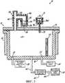
Фиг.1 - схематический вид устройства ХОП согласно сущности изобретения,Figure 1 is a schematic view of an OCR device according to the invention,
фиг.2 - схематический вид альтернативного варианта выполнения простого устройства ХОП согласно изобретению иFIG. 2 is a schematic view of an alternative embodiment of a simple CVD device according to the invention, and
фиг.3 - схематический вид альтернативного варианта выполнения простого устройства ХОП согласно изобретению.figure 3 is a schematic view of an alternative embodiment of a simple device OCP according to the invention.
Подробное описание предпочтительных вариантов осуществления изобретенияDETAILED DESCRIPTION OF PREFERRED EMBODIMENTS
Как показано на фиг.1, устройство ХОП 10 согласно сущности изобретения содержит реакционную камеру 12, состоящую из крышки 14 и сосуда 16. Крышка 14 имеет герметичное соединение с сосудом 16, что при герметичном соединении обычно препятствует поступлению кислорода в реакционную камеру 12. Внутреннее пространство 15 определяет среду для осаждения, когда крышка 14 герметично соединена с сосудом 16, продутым атмосферными газами и вакуумированным. Крышка 14 может быть отсоединена от сосуда 16 для предоставления доступа к внутреннему пространству 15. Реакционная камера 12 изготовлена из металла, стойкого к коррозионному действию реагентов ХОП, как, например, из Inconel 601 или RA 353 MA.As shown in FIG. 1, the OCP device 10 according to the invention comprises a
Инертный газ, как, например, аргон от источника подачи 18 этого газа, подают в реакционную камеру 12 через впускное отверстие 20. Выпускное отверстие 22 реакционной камеры 12 соединено с вакуум-насосом 24, способным вакуумировать реакционную камеру 12 до вакуумметрического давления. Деталь 26 реактивного двигателя вставляют в реакционную камеру 12 и размещают вдали от источника примесного металла, как это объясняется ниже. Реакционную камеру 12 продувают химически активными атмосферными газами, как, например, кислородом, вакуумируя вакуум-насосом 24 внутреннее пространство 15 реакционной камеры 12 до вакуумметрического давления и подавая во внутреннее пространство 15 реакционной камеры 12 инертный газ от источника подачи 18 инертного газа. Реакционную камеру 12 неоднократно вакуумируют и вновь наполняют, пока остаточные концентрации химически активных атмосферных газов не будут достаточно низкими, чтобы не препятствовать последующему осаждению интерметаллического слоя.An inert gas, such as argon from the
Внутри реакционной камеры 12 расположены контейнер или сосуд 27, содержащий в себе массу или навеску твердого материала-донора 28, контейнер или сосуд 29, содержащий в себе массу или навеску материала-активатора 30, и деталь 26 реактивного двигателя. Контейнер 29 расположен на подставке 31, поддерживаемой сосудом 16. Деталь 26 реактивного двигателя может быть изготовлена из любого сверхпрочного сплава. В число подходящих материалов-активаторов 30, пригодных для использования при этом изобретении, входят, но не ограничиваются ими, фторид алюминия, хлорид алюминия, фторид аммония, бифторид аммония и хлорид аммония. В число подходящих твердых материалов-доноров 28 входят сплавы хрома и алюминия, сплавы кобальта и алюминия и сплавы ванадия и алюминия. Чтобы снабдить первым примесным металлом алюминидное или интерметаллическое покрытие 34, образуемое на детали 26, материал-донор 28 может быть использован в виде мелких кусков или порошка, отделенного от детали 26 реактивного двигателя и не зависящего от нее.Inside the
Как также показано на фиг.1, нагревательный элемент 32 при тепловом контакте соединен с реакционной камерой 12 для обеспечения достаточной теплопередачи к материалу-активатору 30. Нагревательный элемент 32 действует для повышения температуры твердого материала-донора 28 и материала-активатора 30 до температуры приблизительно 2200°F, ниже которой испаряется материал-активатор 30. Пар, происходящий из материала-активатора 30, способствует выделению парофазного реагента из твердого материала-донора 28, который ограничен во внутреннем пространстве реакционной камеры 12, содержит примесный металл - обычно алюминий - и действует как источник примесного металла. Согласно изобретению, предполагается, что для увеличения скорости осаждения покрытия через контейнер 29 может быть приложен электрический потенциал постоянного тока при непосредственной связи по постоянному току с деталью 26 реактивного двигателя.As also shown in FIG. 1, the
Снаружи реакционной камеры 12 расположен сравнительно небольшой контейнер 36, в котором находится твердый материал-донор 38. Твердый материал-донор 38, предоставляемый либо в виде сухого твердого вещества, как, например, в гидратированной кристаллической форме, либо в виде жидкости, служит источником второго примесного металла, отдельного и отличимого от детали 26 реактивного двигателя. Второй примесный металл объединяется с первым примесным металлом, подаваемым от материала-донора 28, для образования на детали 26 реактивного двигателя алюминидного покрытия 34, которое на фиг.1 для ясности показано с увеличенной толщиной. Состав твердого материала-донора 38 отличается от состава твердого материала-донора 28, присутствующего в реакционной камере 12.A relatively
Контейнер 36 выполнен с такими размерами, чтобы вмещать в себя твердый материал-донор 38. Реакционная камера 12 выполнена с такими размерами, чтобы вмещать в себя деталь 26 реактивного двигателя. Следовательно, размеры реакционной камеры 12 значительно больше, чем размеры контейнера 36. Так как контейнер 36 и главная камера 12 разделяют среду для осаждения, то остаточные атмосферы в них являются общими. Любой остаточный инертный газ, оставшийся внутри реакционной камеры 12 и контейнера 36 после процесса продувки с вакуумированием и наполнением, представляет собой часть среды для осаждения. Парофазный реагент, содержащий второй примесный металл, перемещается из контейнера 36 в реакционную камеру 12 без помощи находящегося под давлением газа-носителя. Как понятно специалисту в данной области техники, остаточный инертный газ не представляет собой газ-носитель, поскольку не имеется никакого находящегося под давлением потока идентифицируемого газа-носителя, который способен переносить парофазный реагент, содержащий второй примесный металл, из контейнера 36 в реакционную камеру 12. В общем, объем реакционной камеры 12, по меньшей мере, в десять раз больше, чем объем контейнера 36 и трубопровода 40. В примерном варианте осуществления изобретения контейнер 36 имеет объем около 50 см3, реакционная камера 12 имеет объем около 27000 см3, и трубопровод 40 имеет объем около 10 см3.The
Как также показано на фиг.1, внутреннее пространство 39 контейнера 36 соединено при гидравлическом сообщении с внутренним пространством 15 реакционной камеры 12 трубопроводом 40, который может иметь форму тройника, определяющего канал 42 для пара. С этой целью трубопровод 40 имеет два нормально открытых отверстия 41, 43. Отверстие 41 герметично соединено с отверстием 45 контейнера 36, а отверстие 43 соединено при гидравлическом сообщении с реакционной камерой 12, так что реакционная камера 12 и контейнер 36 совместно используют общую и замкнутую среду или атмосферу, которая допускает перенос испарившегося материала-донора 38 в реакционную камеру 12. Канал 42 для пара с пользой свободен от клапанной системы, так что атмосфера внутри контейнера 36 не может быть изолирована от атмосферы внутри реакционной камеры 12. Контейнер 36 изготовлен из материала, способного поддерживать вакуумметрическое давление до 100 Торр. Трубопровод 40 может быть образован трубой с номинальным диаметром 0,5 дюйма и может быть либо сортамента 40, либо сортамента 80 в зависимости от давления в трубопроводе. Контейнер 36 может быть подвешен над крышкой 14 посредством трубопровода 40, может поддерживаться от крышки 14 посредством опорной конструкции (не показана) или может поддерживаться отдельно посредством независимой опорной конструкции (не показана).As also shown in FIG. 1, the
Контейнер 36 можно открывать для пополнения при необходимости навеской из второго твердого материала-донора 38 для смены вида твердого материала-донора 38 с целью подачи другого металла в реакционную камеру 12 или для чистки. Контейнер 36 газонепроницаемым образом герметично и с возможностью съема соединен с трубопроводом 40. С этой целью контейнер 36 содержит кольцевой фланец 48, который может быть газонепроницаемым образом соединен с кольцевым фланцем 50, окружающим отверстие 52 трубопровода 40. Контейнер 36 может быть выложен керамической футеровкой (не показана), как, например, глиноземной футеровкой для предотвращения возникновения коррозии, вызываемой вторым материалом-донором 38. Контейнер 36 может быть выполнен с возможностью получения продувочного потока инертного газа, как, например, аргона через, например, впускное отверстие 54, которое обычно закрыто колпаком. Продувочный поток был бы полезен во время загрузки контейнера 36 массой или навеской второго материала-донора 38 и, кроме того, до или после нанесения покрытия, происходящего в реакционной камере 12. Контейнер 36 может быть сформирован из высокопрочного сплава на основе никеля, как, например, Inco 600, Haynes 120, Inco 601 или Hastelloy C276, который стоек к коррозии хлорид-ионами.The
Как также показано на фиг.1, контейнер 36 и трубопровод 40, ведущий к реакционной камере 12, нагревают соответствующими нагревателями 44, 46. Нагреватель 46 способен нагревать трубопровод 40 до температуры, по меньшей мере, около 1000°F. Действие нагревателя 46 предотвращает осаждение металлического парофазного реагента, перемещаемого из контейнера 36 в реакционную камеру 12, в виде жидкости и/или твердого вещества на внутренних поверхностях трубопровода 40. Нагреватель 44 должен быть способен нагревать контейнер 36 и второй материал-донор 38 до температуры, по меньшей мере, 2000°F за 20 минут. Любой из нагревателей 44, 46 может состоять, например, из многочисленных нагревательных элементов, заделанных в керамический элемент. Подходящие нагревательные элементы имеются на рынке от Kanthal Globar (Ниагара-Фолз, шт.Нью-Йорк, США).As also shown in FIG. 1, the
Обращенная наружу поверхность нагревателей 44, 46 теплоизолирована, так чтобы операторы не могли обжечься, когда контейнер 36 горячий. Контейнер 36 может быть оснащен устройством для измерения температуры (не показано), как, например, термопарой или, точнее, термопарой типа К и устройством индикации температуры (не показано), электрически соединенным с устройством для измерения температуры. Температуру контейнера 36 регулируют так, чтобы она не превышала температуру испарения второго материала-донора 38 больше, чем на около 15°F. Нагреватели 44, 46 могут выборочно включаться оператором или могут работать в автоматическом режиме под управлением управляющего устройства реакционной камеры 12.The outwardly facing surface of the
Как также показано на фиг.1, твердым материалом-донором 38, помещенным в контейнер 36, может быть любая твердая металло-галогеновая кислота Льюиса, имеющая состав, содержащий металлический элемент, выбранный для взаимодействия с металлическим элементом в парофазном реагенте, происходящем из твердого материала-донора 38, для образования алюминидного покрытия на открытой поверхности детали 26 реактивного двигателя. Металло-галогеновая кислота Льюиса обычно поставляется в виде твердого материала в гидратной или безводной форме, как, например, в виде мелких кусков или порошка, хотя изобретение не ограничено этим, и предпочтительно является свободной от алюминия. Такие металло-галогеновые кислоты Льюиса отличаются металлическим элементом, как, например, хромом, цирконием, иттрием, гафнием, платиной, палладием, родием, иридием, титаном, ниобием, кремнием и кобальтом, химически связанным с галогеном, как, например, фтор-, хлор-, бром- и иод-ионом. В число подходящих кислот Льюиса входят, но не ограничиваются ими, AlCl3, CoCl4, CrCl3, CrF3, FeCl3, HfCl3, IrCl3, PtCl4, RhCl3, RuCl3, TiCl4, YCl3, ZrCl4 и ZrF4. Металло-галогеновые кислоты Льюиса могут быть химическими веществами с чистотой по стандарту Американского химического общества или с высокой чистотой реагента и по существу свободны от загрязнений, как, например, серы. При нагревании такие металло-галогеновые кислоты Льюиса преобразуются из формы сухого твердого вещества в форму жидкости, а при увеличении температуры преобразуются из формы жидкости в пар для предоставления парофазного реагента, содержащего примесный металл. Тщательно регулируя температуру контейнера 36, можно использовать регулирование превращения в парофазный реагент для того, чтобы регулировать ввод парофазного реагента в реакционную камеру 12.As also shown in FIG. 1, the
При нагреве до достаточной температуры в контейнере 36 твердый материал-донор 38 образует парофазный реагент, перемещаемый или переносимый по трубопроводу 40 к реакционной камере 12. Реакционная камера 12 и контейнер 36 с пользой совместно используют общую среду или атмосферу, потому что одно нормально открытое отверстие 43 трубопровода 40 соединено при гидравлическом сообщении с внутренним пространством 15 реакционной камеры 12, а другое нормально открытое отверстие 45 герметично соединено с отверстием контейнера 36. Этот подход контрастирует с динамическими системами ХОП, которые вместо этого основываются на пропуске коррозионного газа, как, например, хлористого водорода или газа-носителя, через материал-источник, содержащийся во внешней камере с исходным веществом. Подход согласно изобретению исключает необходимость в источнике газа и в перемещении газа-носителя или коррозионного газа от источника газа к контейнеру 36, требующихся при динамической системе ХОП. Масса или навеска твердого материала-донора 39, введенного в контейнер 36, регулирует состав алюминидного покрытия, образующегося на детали 26 реактивного двигателя. Например, масса твердого материала-донора 39 может быть изменена так, чтобы покрытие 34 содержало менее 10 вес.% металлического элемента из твердого материала-донора 38.When heated to a sufficient temperature in the
Согласно изобретению предполагается, что реакционная камера 12 может содержать опорную плиту, на которой расположены деталь 26 реактивного двигателя, контейнер 27, контейнер 29 и колпак, который изготовлен из металла и может быть отсоединен от опорной плиты для доступа. В этом альтернативном варианте осуществления изобретения трубопровод 40 от контейнера 36 был бы соединен с внутренним пространством 15 через колпак. Кроме того, согласно изобретению предполагается, что в альтернативном варианте осуществления изобретения материал-донор 38 в контейнере 36 может быть твердым материалом-активатором, который при нагревании до достаточной температуры способен предоставлять дополнительный материал-активатор в реакционную камеру 12.According to the invention, it is contemplated that the
Как также показано на фиг.1, при использовании устройства в реакционную камеру 12 помещают деталь 26 реактивного двигателя, навеску первого материала-донора 28 и навеску материала-активатора 30, а в контейнер 36 - навеску второго материала-донора. Продувают атмосферными газами внутреннее пространство 39 контейнера 36 и внутреннее пространство 15 реакционной камеры 12, неоднократно впуская инертный газ от источника подачи 18 инертного газа через впускное отверстие 20 и вакуумируя вакуум-насосом 24 через выпускное отверстие 22. После последнего цикла продувки вакуумируют до вакуумметрического давления около 100 Торр. Первый металлический компонент, вводимый в алюминидное покрытие 34, выделяется из первого материала-донора 28 в виде первого парофазного реагента при посредничестве паров нагретого материала-активатора 30, которые образуются при нагреве, как это схематически показано с обозначением позицией 33. Диффузия первого парофазного реагента к детали 26 реактивного двигателя схематически показана с обозначением позицией 35.As also shown in FIG. 1, when using the device, a
Контейнер 36 нагревают нагревателями 44 до температуры, эффективной для образования второго парофазного реагента из твердого материала-донора 38, который доставляется к реакционной камере 12 по нагретому трубопроводу 40, как это схематически показано с обозначением позицией 37. Таким образом, второй примесный металл вводится в главную реакционную камеру 12 уже в паровой фазе, но отдельно от другого примесного металла. Примесные металлы, присутствующие в отдельных парофазных реагентах, объединяются у открытой поверхности детали 26 реактивного двигателя и образуют на детали 26 реактивного двигателя алюминидное покрытие 34, содержащее разные примесные металлы. Как понятно специалистам в данной области техники, в процесс нанесения покрытия могут быть включены дополнительные стадии, как, например, циклы выдержки и очистки. Извлекают деталь 26 реактивного двигателя из реакционной камеры 12. В нагретой окислительной среде, как, например, в той, в которой деталь 26 реактивного двигателя функционирует на самолете, окисление открытой поверхности алюминидного покрытия 34 приводит к образованию сложного оксида, который защищает нижележащий высокопрочный сплав от повреждения.The
Что касается этого конкретного случая применения, алюминидное покрытие 34 на детали 26 реактивного двигателя имеет ограниченный срок службы и постепенно разрушается. Деталь 26 реактивного двигателя нужно периодически проверять и, возможно, снимать с эксплуатации для повторного нанесения алюминидного покрытия 34. С другой стороны, можно с регулярными интервалами снимать деталь 26 двигателя внутреннего сгорания для повторного нанесения алюминидного покрытия 34. После снятия детали 26 с эксплуатации удаляют любой существующий слой сложного оксида и остаточное алюминидное покрытие 34 на детали 26 реактивного двигателя, например, снятием кислотой и/или дробеструйной очисткой для обнажения свежей поверхности детали 26. Деталь 26 реактивного двигателя снова покрывают другим алюминидным покрытием 34 в соответствии с сущностью изобретения и вновь возвращают на эксплуатацию.Regarding this particular application, the
Как показано на фиг.2, на которой одинаковыми позициями обозначены одинаковые детали, контейнер 36 может быть расположен наверху крышки 14 и в контакте с этой крышкой, служащей конструктивной опорой. При этом расположении благодаря сокращению длины трубопровода 40 уменьшается путь перемещения в реакционную камеру 12 парофазного реагента, происходящего из второго материала-донора 38 в контейнере 36. Такое расположение можно осуществить, изменяя размеры трубопровода 40.As shown in FIG. 2, in which identical parts denote identical parts, the
В альтернативном варианте осуществления изобретения, показанном на фиг.2, второй контейнер 36а может быть пассивно соединен при закрытом гидравлическом сообщении с реакционной камерой 12. Контейнер 36а по существу одинаков с контейнером 36, за исключением того, что он вмещает материал-донор 56, который содержит третий примесный металл, отличающийся по составу от примесных металлов в материалах-донорах 28, 38. Контейнер 36а соединен закрытым ходом с реакционной камерой 12, так что парофазный реагент, происходящий из материала-донора 56, можно перемещать к реакционной камере 12, не прибегая к потоку газа-носителя. Таким образом, примесный металл из контейнера 36а вводят в главную реакционную камеру уже в паровой фазе, но отдельно от других примесных металлов. Три примесных металла в их соответствующих паровых фазах объединяются у поверхности детали 26 реактивного двигателя для образования интерметаллического слоя, содержащего многочисленные примесные металлы.In the alternative embodiment of FIG. 2, the second container 36a may be passively connected in fluid communication with the
Согласно сущности изобретения простая система ХОП согласно изобретению с добавленным контейнером 36а может быть также использована, например, для нанесения второго покрытия на открытую поверхность ранее нанесенного алюминидного покрытия. Например, покрытие из иттрия, закрывающее алюминидное покрытие, было бы связано с серой, которая в противном случае могла бы оказывать вредные воздействия на характеристики алюминида, когда деталь 26 реактивного двигателя находилась бы в эксплуатации. Технологический процесс нанесения второго покрытия включал бы в себя понижение температуры контейнера 36 после образования на детали 26 реактивного двигателя первого покрытия из примесных металлов от материалов-доноров 28, 38, так чтобы материал-донор 38 больше не испарялся, и нагревание контейнера 36а, так чтобы материал-донор 56 испарялся для перемещения в реакционную камеру 12.According to the essence of the invention, the simple OCP system according to the invention with an added container 36a can also be used, for example, for applying a second coating to the exposed surface of a previously applied aluminide coating. For example, a yttrium coating covering the aluminide coating would be associated with sulfur, which would otherwise have harmful effects on the aluminide performance when the
Согласно еще одному альтернативному варианту осуществления изобретения, также показанному на фиг.2, с впускным отверстием 54а второго контейнера 36 соединен третий контейнер 36b. Контейнер 36b по существу одинаков с контейнерами 36, 36а, за исключением того, что он содержит в себе материал-донор 58, отличающийся по составу от примесных металлов, происходящих от материалов-доноров 28, 38 и 56. В частности, контейнер 36b соединен закрытым ходом с контейнером 36а и реакционной камерой 12, так что парофазный реагент, происходящий от материала-донора 58, и парофазный реагент, происходящий от материала-донора 56 и содержащий четвертый примесный металл, можно перемещать в реакционную камеру 12 в отсутствие потока газа-носителя. В соответствии с сущностью изобретения простая система ХОП согласно изобретению с дополнительным контейнером 36b может быть использована для того, чтобы подавать четвертый примесный металл в реакционную камеру 12 для нанесения на открытую поверхность детали 26 реактивного двигателя сложных покрытий, содержащих вплоть до четырех отдельных примесных металлов. Например, могут быть нанесены два покрытия во взаимодействии с дополнительными примесными металлами, происходящими из контейнеров 36, 36а, 36b, как, например, переходное покрытие, переходящее по составу от алюминида к цирконию и, в частности, стабилизированному иттрием цирконию. Определенные примесные металлы, подаваемые к детали 26 реактивного двигателя и объединяемые у нее, выбирали бы, регулируя температуры контейнеров 36, 36а, 36b. Такое ступенчатое покрытие становилось бы эффективной подложкой для стабилизированного иттрием циркония, осажденного при последующем процессе физического осаждения из паров (ФОП).According to yet another alternative embodiment of the invention, also shown in FIG. 2, a
Согласно еще одному альтернативному варианту осуществления изобретения, показанному на фиг.3, источник 60 исходного вещества соединен с реакционной камерой 12 транспортным трубопроводом 62. Источник 60 исходного вещества загружен некоторым количеством подходящего исходного вещества, содержащего примесный металл, и нагрет до температуры, при которой исходное вещество создает соответствующее давление пара для возможности его переноса газом-носителем в реакционную камеру 12. С этой целью по подающей трубе 66 обеспечивается регулируемый поток газа-носителя от источника 64 подачи газа-носителя к источнику 60 исходного вещества. Газ-носитель течет через источник 60 исходного вещества и тем самым уносит пары исходного вещества, смешиваясь с ними для образования газовой смеси, содержащей примесный металл, который по транспортному трубопроводу 62 переносится к реакционной камере 12. Источник 60 исходного вещества замещает и заменяет контейнеры 27, 29 (фиг.1), так как первый примесный металл доставляется от источника 60 исходного вещества, а не от твердого материала-донора 28. Примесный металл, происходящий от источника 60 исходного вещества, таким образом, вводится в главную реакционную камеру отдельно от другого примесного металла, перемещающегося из контейнера 36. Примесные металлы в их паровых фазах затем могут химически объединяться у поверхности детали 26 реактивного двигателя для образования интерметаллического слоя, содержащего многочисленные примесные металлы.According to another alternative embodiment of the invention shown in FIG. 3, the
Согласно еще одному альтернативному варианту осуществления изобретения, также показанному на фиг.3, внутреннее пространство 71 контейнера 36 с прямым отрезком нагретого трубопровода 70 соединено закрытым ходом с реакционной камерой 12. Как и в контейнерах 36, 36а, 36b, в контейнере 36 с образуется парофазный реагент от подходящего материала-донора 72 для пассивного перемещения через трубопровод 70 в реакционную камеру 12 без помощи потока газа-носителя. Вход в трубопровод 70 расположен в верхней части внутреннего пространства 71 над навеской из материала-донора 72, так что парофазный реагент может входить в трубопровод 70 для перемещения в реакционную камеру 12. Внутреннее пространство 71 контейнера 36 с доступно благодаря съемной крышке 74 и нагревается нагревателем 76.According to another alternative embodiment of the invention, also shown in FIG. 3, the
Хотя настоящее изобретение было пояснено описанием варианта его осуществления и конкретными примерами, и хотя этот вариант осуществления изобретения описан со значительными подробностями, он, как предполагают, не ограничивает или никоим образом не лимитирует такими подробностями пределы прилагаемой формулы изобретения. Для специалистов в данной области техники будут легко понятны дополнительные преимущества и модификации. Например, трубопровод 40 может быть выполнен в форме колена, а не тройника. Следовательно, изобретение в его более широких аспектах не ограничивается конкретными подробностями, характерным устройством и способами и показанными и описанными иллюстративными примерами. Таким образом, могут быть сделаны отклонения от таких подробностей, не выходя при этом за пределы общей изобретательской идеи заявителя или не отклоняясь от ее сущности.Although the present invention has been illustrated by a description of a variant of its implementation and specific examples, and although this embodiment of the invention is described with significant details, it is not intended to limit or in any way limit the details of the scope of the attached claims. For those skilled in the art, additional advantages and modifications will be readily apparent. For example,
Claims (37)
Translated fromRussianApplications Claiming Priority (2)
| Application Number | Priority Date | Filing Date | Title |
|---|---|---|---|
| US10/613,620US7390535B2 (en) | 2003-07-03 | 2003-07-03 | Simple chemical vapor deposition system and methods for depositing multiple-metal aluminide coatings |
| US10/613,620 | 2003-07-03 |
Publications (2)
| Publication Number | Publication Date |
|---|---|
| RU2005141760A RU2005141760A (en) | 2006-06-27 |
| RU2352685C2true RU2352685C2 (en) | 2009-04-20 |
Family
ID=33552733
Family Applications (1)
| Application Number | Title | Priority Date | Filing Date |
|---|---|---|---|
| RU2005141760/02ARU2352685C2 (en) | 2003-07-03 | 2004-07-01 | Simple system of chemical deposition from vapours and plating methods of many-metallic aluminide coatings |
Country Status (6)
| Country | Link |
|---|---|
| US (2) | US7390535B2 (en) |
| EP (1) | EP1651793B1 (en) |
| AT (1) | ATE422562T1 (en) |
| DE (1) | DE602004019423D1 (en) |
| RU (1) | RU2352685C2 (en) |
| WO (1) | WO2005060383A2 (en) |
Cited By (2)
| Publication number | Priority date | Publication date | Assignee | Title |
|---|---|---|---|---|
| RU2619419C2 (en)* | 2011-10-19 | 2017-05-15 | Дженерал Электрик Компани | Application method of titanium aluminide and product with titanium aluminide surface |
| RU2727634C1 (en)* | 2017-02-08 | 2020-07-22 | Пикосан Ой | Device for deposition or cleaning with movable structure and method of operation thereof |
Families Citing this family (20)
| Publication number | Priority date | Publication date | Assignee | Title |
|---|---|---|---|---|
| US6451692B1 (en)* | 2000-08-18 | 2002-09-17 | Micron Technology, Inc. | Preheating of chemical vapor deposition precursors |
| JP4217870B2 (en)* | 2002-07-15 | 2009-02-04 | 日本電気株式会社 | Organosiloxane copolymer film, manufacturing method thereof, growth apparatus, and semiconductor device using the copolymer film |
| US7390535B2 (en)* | 2003-07-03 | 2008-06-24 | Aeromet Technologies, Inc. | Simple chemical vapor deposition system and methods for depositing multiple-metal aluminide coatings |
| US20060057418A1 (en)* | 2004-09-16 | 2006-03-16 | Aeromet Technologies, Inc. | Alluminide coatings containing silicon and yttrium for superalloys and method of forming such coatings |
| US9133718B2 (en)* | 2004-12-13 | 2015-09-15 | Mt Coatings, Llc | Turbine engine components with non-aluminide silicon-containing and chromium-containing protective coatings and methods of forming such non-aluminide protective coatings |
| WO2008085816A1 (en)* | 2007-01-03 | 2008-07-17 | The Penn State Research Foundation | Coatings to inhibit formation of deposits from elevated temperature contact with hydrocarbons |
| DE102008026974A1 (en)* | 2008-06-03 | 2009-12-10 | Aixtron Ag | Method and apparatus for depositing thin layers of polymeric para-xylylenes or substituted para-xylylenes |
| US20090317547A1 (en)* | 2008-06-18 | 2009-12-24 | Honeywell International Inc. | Chemical vapor deposition systems and methods for coating a substrate |
| RU2388770C2 (en)* | 2008-07-24 | 2010-05-10 | Химический факультет МГУ имени М.В. Ломоносова | Method of making thin films of chemical compounds and installation for realising said method |
| US8778445B2 (en)* | 2009-05-08 | 2014-07-15 | Mt Coatings, Llc | Apparatus and methods for forming modified metal coatings |
| US20110008972A1 (en)* | 2009-07-13 | 2011-01-13 | Daniel Damjanovic | Methods for forming an ald sio2 film |
| WO2011146547A1 (en)* | 2010-05-17 | 2011-11-24 | Aeromet Technologies, Inc. | Chemical vapor deposition of metal layers for improved brazing |
| US20120073568A1 (en)* | 2010-09-23 | 2012-03-29 | Applied Nanstructured Solutions, Llc. | Methods for in situ deposition of coatings and articles produced using same |
| CN104762600B (en)* | 2015-04-20 | 2017-05-10 | 京东方科技集团股份有限公司 | Evaporated crucible and evaporation device |
| US11393703B2 (en) | 2018-06-18 | 2022-07-19 | Applied Materials, Inc. | Apparatus and method for controlling a flow process material to a deposition chamber |
| FI129734B (en)* | 2019-04-25 | 2022-08-15 | Beneq Oy | Precursor supply chamber |
| US20210381107A1 (en)* | 2020-06-03 | 2021-12-09 | Micron Technology, Inc. | Material deposition systems, and related methods and microelectronic devices |
| KR20220097268A (en)* | 2020-12-31 | 2022-07-07 | 에이에스엠 아이피 홀딩 비.브이. | Container for Efficient Vaporization of Precursor Materials and Method of Using the Same |
| EP4215649A1 (en) | 2022-01-24 | 2023-07-26 | Ivan Timokhin | Preparation of shaped crystalline layers by use of the inner shape/surface of the ampule as a shape forming surface |
| CN114607941B (en)* | 2022-03-07 | 2025-06-24 | 盛吉盛半导体科技(北京)有限公司 | A precursor transport device and semiconductor equipment |
Citations (2)
| Publication number | Priority date | Publication date | Assignee | Title |
|---|---|---|---|---|
| US5407705A (en)* | 1993-03-01 | 1995-04-18 | General Electric Company | Method and apparatus for producing aluminide regions on superalloy substrates, and articles produced thereby |
| US5407704A (en)* | 1991-12-04 | 1995-04-18 | Howmet Corporation | CVD apparatus and method |
Family Cites Families (115)
| Publication number | Priority date | Publication date | Assignee | Title |
|---|---|---|---|---|
| US2598957A (en) | 1949-02-07 | 1952-06-03 | Dayton Pump & Mfg Co | Panel arrangement for dispensing pumps |
| US2816048A (en) | 1949-08-05 | 1957-12-10 | Onera (Off Nat Aerospatiale) | Process of forming superficial alloys of chromium on metal bodies |
| US3329601A (en) | 1964-09-15 | 1967-07-04 | Donald M Mattox | Apparatus for coating a cathodically biased substrate from plasma of ionized coatingmaterial |
| FR1433497A (en) | 1965-02-16 | 1966-04-01 | Snecma | Process for depositing a protective layer on a metal part by a vapor phase method |
| US3556744A (en) | 1965-08-16 | 1971-01-19 | United Aircraft Corp | Composite metal article having nickel alloy having coats containing chromium and aluminum |
| US3507248A (en) | 1967-06-15 | 1970-04-21 | Ibm | Vacuum evaporation coating apparatus including means for precleaning substrates by ion bombardment |
| US3801357A (en) | 1969-06-30 | 1974-04-02 | Alloy Surfaces Co Inc | Diffusion coating |
| US3979534A (en) | 1974-07-26 | 1976-09-07 | General Electric Company | Protective coatings for dispersion strengthened nickel-chromium/alloys |
| US4084025A (en) | 1974-08-02 | 1978-04-11 | General Electric Company | Process of applying protective aluminum coatings for non-super-strength nickel-chromium alloys |
| US3973270A (en) | 1974-10-30 | 1976-08-03 | Westinghouse Electric Corporation | Charge storage target and method of manufacture |
| GB1545584A (en)* | 1975-03-07 | 1979-05-10 | Onera (Off Nat Aerospatiale) | Processes and systems for the formation of surface diffusion alloys on perforate metal workpieces |
| US4076380A (en) | 1976-10-28 | 1978-02-28 | Bell Telephone Laboratories, Incorporated | Graded index optical fiber |
| JPS53110973A (en)* | 1977-03-10 | 1978-09-28 | Futaba Denshi Kogyo Kk | Method and apparatus for manufacturing compounds |
| US4101714A (en) | 1977-03-31 | 1978-07-18 | General Electric Company | High temperature oxidation resistant dispersion strengthened nickel-chromium alloys |
| JPS5558365A (en) | 1978-10-27 | 1980-05-01 | Hitachi Metals Ltd | Coating method for titanium compound |
| US4264682A (en) | 1978-10-27 | 1981-04-28 | Hitachi Metals, Ltd. | Surface hafnium-titanium compound coated hard alloy material and method of producing the same |
| US4694036A (en) | 1983-06-23 | 1987-09-15 | Alloy Surfaces Company, Inc. | Metal diffusion and use |
| US4220460A (en) | 1979-02-05 | 1980-09-02 | Western Electric Company, Inc. | Vapor delivery system and method |
| US4327134A (en) | 1979-11-29 | 1982-04-27 | Alloy Surfaces Company, Inc. | Stripping of diffusion treated metals |
| US4262035A (en) | 1980-03-07 | 1981-04-14 | Bell Telephone Laboratories, Incorporated | Modified chemical vapor deposition of an optical fiber using an rf plasma |
| US4442589A (en) | 1981-03-05 | 1984-04-17 | International Business Machines Corporation | Method for manufacturing field effect transistors |
| FR2508063A1 (en) | 1981-06-18 | 1982-12-24 | Snecma | STEAM PROCESS FOR THE DEPOSITION OF A PROTECTIVE COATING ON A METAL PART, DEVICE FOR IMPLEMENTING SAME AND PARTS OBTAINED ACCORDING TO SAID METHOD |
| US4396213A (en) | 1981-09-02 | 1983-08-02 | John J. Kirlin | Method of joining pipe ends and joint formed thereby |
| JPS591671A (en) | 1982-05-28 | 1984-01-07 | Fujitsu Ltd | Plasma cvd device |
| US4472476A (en) | 1982-06-24 | 1984-09-18 | United Technologies Corporation | Composite silicon carbide/silicon nitride coatings for carbon-carbon materials |
| US4476178A (en) | 1982-06-24 | 1984-10-09 | United Technologies Corporation | Composite silicon carbide coatings for carbon-carbon materials |
| JPS6097622A (en) | 1983-11-01 | 1985-05-31 | Toshiba Mach Co Ltd | Epitaxial device |
| US4699084A (en) | 1982-12-23 | 1987-10-13 | The United States Of America As Represented By The Secretary Of The Army | Apparatus for producing high quality epitaxially grown semiconductors |
| US5514482A (en)* | 1984-04-25 | 1996-05-07 | Alliedsignal Inc. | Thermal barrier coating system for superalloy components |
| GB2167773A (en) | 1984-11-29 | 1986-06-04 | Secr Defence | Improvements in or relating to coating processes |
| US4698244A (en)* | 1985-10-31 | 1987-10-06 | Air Products And Chemicals, Inc. | Deposition of titanium aluminides |
| US4816291A (en) | 1987-08-19 | 1989-03-28 | The Regents Of The University Of California | Process for making diamond, doped diamond, diamond-cubic boron nitride composite films |
| DE3742944C1 (en) | 1987-12-18 | 1988-10-27 | Mtu Muenchen Gmbh | Oxidation protection layer |
| US4963395A (en) | 1988-06-24 | 1990-10-16 | Combustion Engineering, Inc. | Method of chromizing large size articles |
| US5149376A (en)* | 1988-06-30 | 1992-09-22 | Societe Nationale D'etude Et De Construction De Moteurs D'aviation "S.N.E.C.M.A." | Process and apparatus for the simultaneous deposition of a protective coating on internal and external surfaces of heat-resistant alloy parts |
| US5087531A (en)* | 1988-11-30 | 1992-02-11 | Sharp Kabushiki Kaisha | Electroluminescent device |
| US4915744A (en) | 1989-02-03 | 1990-04-10 | Applied Solar Energy Corporation | High efficiency solar cell |
| US4961958A (en) | 1989-06-30 | 1990-10-09 | The Regents Of The Univ. Of Calif. | Process for making diamond, and doped diamond films at low temperature |
| US5132755A (en) | 1989-07-11 | 1992-07-21 | Oki Electric Industry Co. Ltd. | Field effect transistor |
| US5114559A (en) | 1989-09-26 | 1992-05-19 | Ricoh Company, Ltd. | Thin film deposition system |
| US5139824A (en)* | 1990-08-28 | 1992-08-18 | Liburdi Engineering Limited | Method of coating complex substrates |
| US5071678A (en) | 1990-10-09 | 1991-12-10 | United Technologies Corporation | Process for applying gas phase diffusion aluminide coatings |
| DE4035789C1 (en) | 1990-11-10 | 1991-06-13 | Mtu Muenchen Gmbh | |
| JP3106172B2 (en) | 1991-02-26 | 2000-11-06 | 東京エレクトロン株式会社 | Sealing structure of heat treatment equipment |
| DE4119967C1 (en) | 1991-06-18 | 1992-09-17 | Mtu Muenchen Gmbh | |
| US5211731A (en) | 1991-06-27 | 1993-05-18 | The United States Of Americas As Represented By The Secretary Of The Navy | Plasma chemical vapor deposition of halide glasses |
| US5264245A (en)* | 1991-12-04 | 1993-11-23 | Howmet Corporation | CVD method for forming uniform coatings |
| US5286520A (en) | 1991-12-13 | 1994-02-15 | Ford Motor Company | Preparation of fluorine-doped tungstic oxide |
| TW222345B (en) | 1992-02-25 | 1994-04-11 | Semicondustor Energy Res Co Ltd | Semiconductor and its manufacturing method |
| US6709907B1 (en) | 1992-02-25 | 2004-03-23 | Semiconductor Energy Laboratory Co., Ltd. | Method of fabricating a thin film transistor |
| US5300313A (en) | 1992-12-16 | 1994-04-05 | General Electric Company | Method for determining thickness of chemical vapor deposited layers |
| US5466494A (en)* | 1993-01-29 | 1995-11-14 | Kabushiki Kaisha Komatsu Seisakusho | Method for producing thin film |
| US5902638A (en)* | 1993-03-01 | 1999-05-11 | General Electric Company | Method for producing spallation-resistant protective layer on high performance alloys |
| JP3519406B2 (en) | 1993-03-24 | 2004-04-12 | ジョージア テック リサーチ コーポレイション | Method of combustion chemical vapor deposition of films and coatings |
| US5858465A (en) | 1993-03-24 | 1999-01-12 | Georgia Tech Research Corporation | Combustion chemical vapor deposition of phosphate films and coatings |
| US5377429A (en) | 1993-04-19 | 1995-01-03 | Micron Semiconductor, Inc. | Method and appartus for subliming precursors |
| US5484484A (en) | 1993-07-03 | 1996-01-16 | Tokyo Electron Kabushiki | Thermal processing method and apparatus therefor |
| JP2999346B2 (en)* | 1993-07-12 | 2000-01-17 | オリエンタルエンヂニアリング株式会社 | Substrate surface coating method and coating member |
| GB9315771D0 (en) | 1993-07-30 | 1993-09-15 | Epichem Ltd | Method of depositing thin metal films |
| US6689422B1 (en) | 1994-02-16 | 2004-02-10 | Howmet Research Corporation | CVD codeposition of A1 and one or more reactive (gettering) elements to form protective aluminide coating |
| US5451258A (en) | 1994-05-11 | 1995-09-19 | Materials Research Corporation | Apparatus and method for improved delivery of vaporized reactant gases to a reaction chamber |
| US5658614A (en) | 1994-10-28 | 1997-08-19 | Howmet Research Corporation | Platinum aluminide CVD coating method |
| US5562998A (en)* | 1994-11-18 | 1996-10-08 | Alliedsignal Inc. | Durable thermal barrier coating |
| GB9426257D0 (en)* | 1994-12-24 | 1995-03-01 | Rolls Royce Plc | Thermal barrier coating for a superalloy article and method of application |
| JP3022229B2 (en) | 1994-12-26 | 2000-03-15 | 東洋製罐株式会社 | Method for forming silicon oxide film of uniform thickness on three-dimensional container made of plastics material |
| JP3982844B2 (en) | 1995-01-12 | 2007-09-26 | 株式会社日立国際電気 | Semiconductor manufacturing apparatus and semiconductor manufacturing method |
| US5512382A (en)* | 1995-05-08 | 1996-04-30 | Alliedsignal Inc. | Porous thermal barrier coating |
| US5823416A (en) | 1995-07-28 | 1998-10-20 | Matsushita Electric Industrial Co., Ltd. | Apparatus and method for surface treatment, and apparatus and method for wire bonding using the surface treatment apparatus |
| US5820641A (en) | 1996-02-09 | 1998-10-13 | Mks Instruments, Inc. | Fluid cooled trap |
| TW506620U (en) | 1996-03-15 | 2002-10-11 | Asahi Glass Co Ltd | Low pressure CVD apparatus |
| US5851293A (en) | 1996-03-29 | 1998-12-22 | Atmi Ecosys Corporation | Flow-stabilized wet scrubber system for treatment of process gases from semiconductor manufacturing operations |
| US6162488A (en) | 1996-05-14 | 2000-12-19 | Boston University | Method for closed loop control of chemical vapor deposition process |
| US5849360A (en) | 1996-06-20 | 1998-12-15 | National Science Council | Tube chemical gas deposition method of preparing titanium nitride coated titanium carbide for titanium carbide/silicon nitride composites |
| US5989733A (en)* | 1996-07-23 | 1999-11-23 | Howmet Research Corporation | Active element modified platinum aluminide diffusion coating and CVD coating method |
| US6089184A (en) | 1997-06-11 | 2000-07-18 | Tokyo Electron Limited | CVD apparatus and CVD method |
| US6083321A (en) | 1997-07-11 | 2000-07-04 | Applied Materials, Inc. | Fluid delivery system and method |
| DE19730007C1 (en) | 1997-07-12 | 1999-03-25 | Mtu Muenchen Gmbh | Method and device for the gas phase diffusion coating of workpieces made of heat-resistant material with a coating material |
| US6168874B1 (en)* | 1998-02-02 | 2001-01-02 | General Electric Company | Diffusion aluminide bond coat for a thermal barrier coating system and method therefor |
| GB9811456D0 (en)* | 1998-05-29 | 1998-07-29 | Rolls Royce Plc | A metallic article having a thermal barrier coating and a method of application thereof |
| US6143361A (en) | 1998-10-19 | 2000-11-07 | Howmet Research Corporation | Method of reacting excess CVD gas reactant |
| US6258461B1 (en) | 1999-03-12 | 2001-07-10 | Alloy Surfaces Co., Inc. | Activated nickel screens and foils |
| US6332926B1 (en) | 1999-08-11 | 2001-12-25 | General Electric Company | Apparatus and method for selectively coating internal and external surfaces of an airfoil |
| US6451692B1 (en) | 2000-08-18 | 2002-09-17 | Micron Technology, Inc. | Preheating of chemical vapor deposition precursors |
| US6692324B2 (en) | 2000-08-29 | 2004-02-17 | Ut-Battelle, Llc | Single self-aligned carbon containing tips |
| KR100344103B1 (en) | 2000-09-04 | 2002-07-24 | 에피밸리 주식회사 | The semiconductor device with In(x)Ga(1-x)N passivation layer and the producing method |
| US6602356B1 (en)* | 2000-09-20 | 2003-08-05 | General Electric Company | CVD aluminiding process for producing a modified platinum aluminide bond coat for improved high temperature performance |
| US6488986B2 (en)* | 2001-01-29 | 2002-12-03 | General Electric Company | Combined coat, heat treat, quench method for gas turbine engine components |
| US6649431B2 (en) | 2001-02-27 | 2003-11-18 | Ut. Battelle, Llc | Carbon tips with expanded bases grown with simultaneous application of carbon source and etchant gases |
| US20020166508A1 (en)* | 2001-03-21 | 2002-11-14 | Ryuji Biro | Vacuum deposition system and thin-film deposition process |
| US6605161B2 (en) | 2001-06-05 | 2003-08-12 | Aeromet Technologies, Inc. | Inoculants for intermetallic layer |
| JP4098556B2 (en)* | 2001-07-31 | 2008-06-11 | ローム株式会社 | Terminal board, circuit board provided with the terminal board, and method for connecting the terminal board |
| US6576067B2 (en)* | 2001-08-31 | 2003-06-10 | General Electric Co. | Fabrication of an article having a protective coating with a polished, pre-oxidized protective-coating surface |
| US6793966B2 (en) | 2001-09-10 | 2004-09-21 | Howmet Research Corporation | Chemical vapor deposition apparatus and method |
| US20030111014A1 (en)* | 2001-12-18 | 2003-06-19 | Donatucci Matthew B. | Vaporizer/delivery vessel for volatile/thermally sensitive solid and liquid compounds |
| US6646328B2 (en) | 2002-01-11 | 2003-11-11 | Taiwan Semiconductor Manufacturing Co. Ltd. | Chip antenna with a shielding layer |
| JP2003289072A (en) | 2002-03-28 | 2003-10-10 | Sharp Corp | Substrate having flattening film, substrate for display device, and method of manufacturing those substrates |
| US6967159B2 (en) | 2002-08-28 | 2005-11-22 | Micron Technology, Inc. | Systems and methods for forming refractory metal nitride layers using organic amines |
| US7030042B2 (en) | 2002-08-28 | 2006-04-18 | Micron Technology, Inc. | Systems and methods for forming tantalum oxide layers and tantalum precursor compounds |
| US6995081B2 (en) | 2002-08-28 | 2006-02-07 | Micron Technology, Inc. | Systems and methods for forming tantalum silicide layers |
| US6794284B2 (en) | 2002-08-28 | 2004-09-21 | Micron Technology, Inc. | Systems and methods for forming refractory metal nitride layers using disilazanes |
| US6984592B2 (en) | 2002-08-28 | 2006-01-10 | Micron Technology, Inc. | Systems and methods for forming metal-doped alumina |
| US7087481B2 (en) | 2002-08-28 | 2006-08-08 | Micron Technology, Inc. | Systems and methods for forming metal oxides using metal compounds containing aminosilane ligands |
| US7041609B2 (en) | 2002-08-28 | 2006-05-09 | Micron Technology, Inc. | Systems and methods for forming metal oxides using alcohols |
| US6730164B2 (en) | 2002-08-28 | 2004-05-04 | Micron Technology, Inc. | Systems and methods for forming strontium- and/or barium-containing layers |
| US7112485B2 (en) | 2002-08-28 | 2006-09-26 | Micron Technology, Inc. | Systems and methods for forming zirconium and/or hafnium-containing layers |
| US6958300B2 (en) | 2002-08-28 | 2005-10-25 | Micron Technology, Inc. | Systems and methods for forming metal oxides using metal organo-amines and metal organo-oxides |
| US6784049B2 (en) | 2002-08-28 | 2004-08-31 | Micron Technology, Inc. | Method for forming refractory metal oxide layers with tetramethyldisiloxane |
| US6803135B2 (en)* | 2003-02-24 | 2004-10-12 | Chromalloy Gas Turbine Corporation | Thermal barrier coating having low thermal conductivity |
| US7115528B2 (en) | 2003-04-29 | 2006-10-03 | Micron Technology, Inc. | Systems and method for forming silicon oxide layers |
| US7390535B2 (en)* | 2003-07-03 | 2008-06-24 | Aeromet Technologies, Inc. | Simple chemical vapor deposition system and methods for depositing multiple-metal aluminide coatings |
| US7211509B1 (en) | 2004-06-14 | 2007-05-01 | Novellus Systems, Inc, | Method for enhancing the nucleation and morphology of ruthenium films on dielectric substrates using amine containing compounds |
| US20060057418A1 (en)* | 2004-09-16 | 2006-03-16 | Aeromet Technologies, Inc. | Alluminide coatings containing silicon and yttrium for superalloys and method of forming such coatings |
| US8137820B2 (en)* | 2006-02-24 | 2012-03-20 | Mt Coatings, Llc | Roughened coatings for gas turbine engine components |
| US8778445B2 (en)* | 2009-05-08 | 2014-07-15 | Mt Coatings, Llc | Apparatus and methods for forming modified metal coatings |
| WO2011146547A1 (en)* | 2010-05-17 | 2011-11-24 | Aeromet Technologies, Inc. | Chemical vapor deposition of metal layers for improved brazing |
- 2003
- 2003-07-03USUS10/613,620patent/US7390535B2/ennot_activeExpired - Lifetime
- 2004
- 2004-07-01EPEP04820715Apatent/EP1651793B1/ennot_activeExpired - Lifetime
- 2004-07-01DEDE602004019423Tpatent/DE602004019423D1/ennot_activeExpired - Lifetime
- 2004-07-01ATAT04820715Tpatent/ATE422562T1/ennot_activeIP Right Cessation
- 2004-07-01WOPCT/US2004/021341patent/WO2005060383A2/enactiveApplication Filing
- 2004-07-01RURU2005141760/02Apatent/RU2352685C2/enactive
- 2008
- 2008-06-19USUS12/142,539patent/US8839740B2/ennot_activeExpired - Lifetime
Patent Citations (2)
| Publication number | Priority date | Publication date | Assignee | Title |
|---|---|---|---|---|
| US5407704A (en)* | 1991-12-04 | 1995-04-18 | Howmet Corporation | CVD apparatus and method |
| US5407705A (en)* | 1993-03-01 | 1995-04-18 | General Electric Company | Method and apparatus for producing aluminide regions on superalloy substrates, and articles produced thereby |
Cited By (3)
| Publication number | Priority date | Publication date | Assignee | Title |
|---|---|---|---|---|
| RU2619419C2 (en)* | 2011-10-19 | 2017-05-15 | Дженерал Электрик Компани | Application method of titanium aluminide and product with titanium aluminide surface |
| RU2727634C1 (en)* | 2017-02-08 | 2020-07-22 | Пикосан Ой | Device for deposition or cleaning with movable structure and method of operation thereof |
| US11725279B2 (en) | 2017-02-08 | 2023-08-15 | Picosun Oy | Deposition or cleaning apparatus with movable structure |
Also Published As
| Publication number | Publication date |
|---|---|
| EP1651793B1 (en) | 2009-02-11 |
| US8839740B2 (en) | 2014-09-23 |
| EP1651793A2 (en) | 2006-05-03 |
| US20080245302A1 (en) | 2008-10-09 |
| WO2005060383A2 (en) | 2005-07-07 |
| WO2005060383A3 (en) | 2005-11-17 |
| DE602004019423D1 (en) | 2009-03-26 |
| US7390535B2 (en) | 2008-06-24 |
| US20050000425A1 (en) | 2005-01-06 |
| ATE422562T1 (en) | 2009-02-15 |
| RU2005141760A (en) | 2006-06-27 |
Similar Documents
| Publication | Publication Date | Title |
|---|---|---|
| RU2352685C2 (en) | Simple system of chemical deposition from vapours and plating methods of many-metallic aluminide coatings | |
| JP7737929B2 (en) | Coatings for enhancing the properties and performance of substrate articles and devices | |
| EP2628821B1 (en) | Apparatus and methods for deposition reactors | |
| US7562672B2 (en) | Chemical delivery apparatus for CVD or ALD | |
| US8778445B2 (en) | Apparatus and methods for forming modified metal coatings | |
| JP2014007289A (en) | Gas supply device and film forming device | |
| JP2003113473A (en) | Apparatus and method for chemical vapor deposition | |
| US5407705A (en) | Method and apparatus for producing aluminide regions on superalloy substrates, and articles produced thereby | |
| US7955569B2 (en) | Metal halide reactor for CVD and method | |
| JP4535620B2 (en) | Method and apparatus for controlling excess CVD reactant | |
| CN105039930A (en) | Apparatus and methods for slurry aluminide coating repair | |
| US20080107808A1 (en) | Method and an apparatus for the coating of a base body | |
| US5141773A (en) | Method of forming a carbide on a carbon substrate | |
| HK1168876B (en) | Apparatus and methods for forming modified metal coatings | |
| Lieberman | Design of production chemical vapor deposition equipment | |
| JP2011035113A (en) | Method of manufacturing semiconductor device, and substrate processing device | |
| JP2004300500A (en) | Member with film deposited thereon, and method for depositing film | |
| JPS6160882A (en) | Reaction furnace |
Legal Events
| Date | Code | Title | Description |
|---|---|---|---|
| PC4A | Invention patent assignment | Effective date:20100322 |