RU2352291C2 - Device for implantation in blood vessels and its versions - Google Patents
Device for implantation in blood vessels and its versionsDownload PDFInfo
- Publication number
- RU2352291C2 RU2352291C2RU2007112022/14ARU2007112022ARU2352291C2RU 2352291 C2RU2352291 C2RU 2352291C2RU 2007112022/14 ARU2007112022/14 ARU 2007112022/14ARU 2007112022 ARU2007112022 ARU 2007112022ARU 2352291 C2RU2352291 C2RU 2352291C2
- Authority
- RU
- Russia
- Prior art keywords
- filter element
- filtering element
- implantation
- blood
- blood vessels
- Prior art date
Links
- 238000002513implantationMethods0.000titleclaimsabstractdescription7
- 210000004204blood vesselAnatomy0.000titleclaimsabstractdescription6
- 238000000605extractionMethods0.000claimsabstractdescription11
- 239000000463materialSubstances0.000claimsabstractdescription6
- 210000003850cellular structureAnatomy0.000claimsabstractdescription5
- 238000001914filtrationMethods0.000abstractdescription8
- 239000003814drugSubstances0.000abstractdescription3
- 230000035515penetrationEffects0.000abstractdescription2
- 238000007631vascular surgeryMethods0.000abstractdescription2
- 239000003795chemical substances by applicationSubstances0.000abstract1
- 230000000694effectsEffects0.000abstract1
- 239000000126substanceSubstances0.000abstract1
- 230000002792vascularEffects0.000description3
- 208000005189EmbolismDiseases0.000description2
- 208000010378Pulmonary EmbolismDiseases0.000description2
- 238000002399angioplastyMethods0.000description2
- 210000001367arteryAnatomy0.000description2
- 210000004027cellAnatomy0.000description2
- 210000003734kidneyAnatomy0.000description2
- 210000003141lower extremityAnatomy0.000description2
- 206010073734MicroembolismDiseases0.000description1
- 208000001435ThromboembolismDiseases0.000description1
- 208000007536ThrombosisDiseases0.000description1
- 230000015572biosynthetic processEffects0.000description1
- 210000001715carotid arteryAnatomy0.000description1
- 235000019994cavaNutrition0.000description1
- 210000004351coronary vesselAnatomy0.000description1
- 210000003128headAnatomy0.000description1
- 210000002216heartAnatomy0.000description1
- 230000003993interactionEffects0.000description1
- 238000001990intravenous administrationMethods0.000description1
- 230000003902lesionEffects0.000description1
Images

Landscapes
- External Artificial Organs (AREA)
- Surgical Instruments (AREA)
- Prostheses (AREA)
- Media Introduction/Drainage Providing Device (AREA)
Abstract
Description
Translated fromRussianИзобретение относится к медицине, в частности к сосудистой хирургии.The invention relates to medicine, in particular to vascular surgery.
Известна конструкция кава-фильтра, выполненная в виде двух соосно установленных упругих спиралей с перекрещивающимися между собой в центре улавливающими нитями из рассасыващего материала /см. патент RU №2094063, 1997/.A known design of a cava filter made in the form of two coaxially mounted elastic spirals with catching threads of absorbable material intersecting each other in the center / cm. RU patent No. 2094063, 1997 /.
Известен интравенозный фильтр, выполненный в виде тела вращения из проволочных элементов, образующих ячейки, и имеющий тяги для его извлечения /см. описание изобретения к заявке RU №94014593, 1993/.Known intravenous filter, made in the form of a body of revolution from the wire elements forming the cell, and having traction for its extraction / see Description of the invention to the application RU No. 94014593, 1993 /.
Известен внутрисосудистый стент-фильтр, выполненный в виде тела вращения ячеистой структуры с возможностью образования фильтрующего элемента, расположенного либо внутри стента, либо снаружи, и имеющий средство для извлечения /см. патент RU №2143246, 1999, прототип/.Known intravascular stent filter, made in the form of a body of rotation of the cellular structure with the possibility of the formation of a filter element located either inside the stent or outside, and having a means for extraction / see patent RU No. 2143246, 1999, prototype /.
Общим недостатком известных устройств является низкая улавливающая /фильтрующая/ способность мельчайших тромбоэмбол размером 100-200 мкм. Вследствие этого последние могут проникать сквозь ячейки тела вращения в сосудистое русло. Это в свою очередь может привести к эмболии дистально расположенных сосудов, вызывая тромбозы артерий головы, сердца, почек, нижних конечностей или легочную тромбоэмболию.A common disadvantage of the known devices is the low capture / filtering / ability of the smallest thromboembolas with a size of 100-200 microns. As a result, the latter can penetrate through the cells of the body of revolution into the vascular bed. This in turn can lead to embolism of distally located vessels, causing thrombosis of the arteries of the head, heart, kidneys, lower extremities or pulmonary thromboembolism.
Задача заявленного технического решения заключается в создании устройства, которое позволит исключить недостатки известных решений и повысить технические характеристики за счет повышения фильтрующей способности устройства, что благоприятно скажется на качестве проведения операций ангиопластики и стентирования сонных и коронарных артерий, артерий почек и нижних конечностей и при легочной тромбоэмболии.The objective of the claimed technical solution is to create a device that will eliminate the disadvantages of the known solutions and increase the technical characteristics by increasing the filtering ability of the device, which will favorably affect the quality of operations of angioplasty and stenting of the carotid and coronary arteries, arteries of the kidneys and lower extremities and with pulmonary thromboembolism .
Для решения этой задачи известное устройство для имплантации в кровеносные сосуды, выполненное в виде тела вращения с ячеистой структурой с фильтрующим элементом и средством для извлечения, имеет дополнительный фильтрующий элемент, который выполнен из кровепроницаемого материала, расположен внутри основного фильтрующего элемента и плотно с ним соединен. Как вариант дополнительный фильтрующий элемент может быть плотно соединен с фильтрующим элементом по окружности его основания. Для извлечения устройства из сосудистого русла используют гибкую тягу с петлей или крючком на ее конце, взаимодействующую со средством для извлечения.To solve this problem, the known device for implantation in blood vessels, made in the form of a body of revolution with a cellular structure with a filter element and means for extraction, has an additional filter element, which is made of a blood-proof material, is located inside the main filter element and is tightly connected to it. Alternatively, the additional filter element can be tightly connected to the filter element around the circumference of its base. To remove the device from the vascular bed, flexible traction is used with a loop or hook at its end, interacting with the extraction tool.
Такое выполнение устройства значительно повышает его технические характеристики за счет возможности улавливания микроэмбол.This embodiment of the device significantly increases its technical characteristics due to the possibility of trapping microembolism.
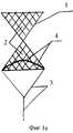
На фиг.1 изображено заявленное устройство, общий вид. Дополнительный фильтрующий элемент плотно соединен с внутренней поверхностью фильтрующего элемента.Figure 1 shows the claimed device, a General view. The additional filter element is tightly connected to the inner surface of the filter element.
На фиг.1а - то же. Дополнительный фильтрующий элемент плотно соединен с фильтрующим элементом по окружности его основания.On figa - the same. The additional filter element is tightly connected to the filter element around the circumference of its base.
На фиг.2 - гибкая тяга с петлей на ее конце.Figure 2 - flexible traction with a loop at its end.
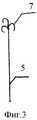
На фиг.3 - то же с крючком.Figure 3 is the same with the hook.
Устройство для имплантации в кровеносные сосуды выполнено в виде тела вращения 1 ячеистой структуры с основным фильтрующим элементом 2 и средством для извлечения 3. Дополнительный фильтрующий элемент 4 из кровепроницаемого материала расположен внутри основного фильтрующего элемента 2 и плотно соединен с его внутренней поверхностью. В качестве варианта дополнительный фильтрующий элемент 4 может быть плотно соединен с основным фильтрующим элементом 2 по окружности его основания. Для удаления устройства из сосудистого русла используют гибкую тягу 5 с петлей 6 или крючком 7 на ее конце для взаимодействия со средством для извлечения 3.The device for implantation into blood vessels is made in the form of a honeycomb
Работа с устройством для имплантации осуществляется следующим образом.Work with the device for implantation is as follows.
Устройство помещают в полой трубке (не изображена) и через пункцию сосуда доставляют дистальнее пораженного сегмента (в случае использования в артериальной системе), затем устройство выталкивают из трубки в просвет сосуда, где оно самофиксируется в планируемом месте. Затем производят ангиопластику и стентирование проксимально расположенного поражения сосуда без боязни дистальной тромбоэмболии. Удаление устройства осуществляют путем взаимодействия гибкой тяги 5 с петлей 6 или крючком 7 со средством для извлечения 3.The device is placed in a hollow tube (not shown) and delivered through the puncture of the vessel distal to the affected segment (if used in the arterial system), then the device is pushed out of the tube into the lumen of the vessel, where it is self-fixed in the planned place. Then angioplasty and stenting of a proximal located vessel lesion are performed without fear of distal thromboembolism. The removal of the device is carried out by the interaction of the
Наличие дополнительного фильтрующего элемента 4 позволяет надежно противодействовать проникновению тромбоэмбол в дистально расположенные сосуды, обеспечив тем самым качество проведения операции и повысив безопасность больного.The presence of an
Claims (3)
Translated fromRussianPriority Applications (1)
| Application Number | Priority Date | Filing Date | Title |
|---|---|---|---|
| RU2007112022/14ARU2352291C2 (en) | 2007-04-03 | 2007-04-03 | Device for implantation in blood vessels and its versions |
Applications Claiming Priority (1)
| Application Number | Priority Date | Filing Date | Title |
|---|---|---|---|
| RU2007112022/14ARU2352291C2 (en) | 2007-04-03 | 2007-04-03 | Device for implantation in blood vessels and its versions |
Publications (2)
| Publication Number | Publication Date |
|---|---|
| RU2007112022A RU2007112022A (en) | 2008-10-10 |
| RU2352291C2true RU2352291C2 (en) | 2009-04-20 |
Family
ID=39927373
Family Applications (1)
| Application Number | Title | Priority Date | Filing Date |
|---|---|---|---|
| RU2007112022/14ARU2352291C2 (en) | 2007-04-03 | 2007-04-03 | Device for implantation in blood vessels and its versions |
Country Status (1)
| Country | Link |
|---|---|
| RU (1) | RU2352291C2 (en) |
Citations (6)
| Publication number | Priority date | Publication date | Assignee | Title |
|---|---|---|---|---|
| RU2071355C1 (en)* | 1994-04-19 | 1997-01-10 | Заза Александрович Кавтеладзе | Intravenous filter |
| RU2143246C1 (en)* | 1999-06-03 | 1999-12-27 | Балан Александр Наумович | Intravascular stent-filter |
| WO2000056390A1 (en)* | 1999-03-19 | 2000-09-28 | Nmt Medical, Inc. | Free standing filter |
| WO2001074255A1 (en)* | 2000-03-31 | 2001-10-11 | Bacchus Vascular Inc. | Expansible shearing catheters for thrombus and occlusive material removal |
| WO2003073962A1 (en)* | 2002-03-05 | 2003-09-12 | Salviac Limited | An embolic protection system |
| RU2294714C2 (en)* | 2005-04-21 | 2007-03-10 | Александр Наумович Балан | Device for protection of small-diameter vessels |
- 2007
- 2007-04-03RURU2007112022/14Apatent/RU2352291C2/ennot_activeIP Right Cessation
Patent Citations (6)
| Publication number | Priority date | Publication date | Assignee | Title |
|---|---|---|---|---|
| RU2071355C1 (en)* | 1994-04-19 | 1997-01-10 | Заза Александрович Кавтеладзе | Intravenous filter |
| WO2000056390A1 (en)* | 1999-03-19 | 2000-09-28 | Nmt Medical, Inc. | Free standing filter |
| RU2143246C1 (en)* | 1999-06-03 | 1999-12-27 | Балан Александр Наумович | Intravascular stent-filter |
| WO2001074255A1 (en)* | 2000-03-31 | 2001-10-11 | Bacchus Vascular Inc. | Expansible shearing catheters for thrombus and occlusive material removal |
| WO2003073962A1 (en)* | 2002-03-05 | 2003-09-12 | Salviac Limited | An embolic protection system |
| RU2294714C2 (en)* | 2005-04-21 | 2007-03-10 | Александр Наумович Балан | Device for protection of small-diameter vessels |
Also Published As
| Publication number | Publication date |
|---|---|
| RU2007112022A (en) | 2008-10-10 |
Similar Documents
| Publication | Publication Date | Title |
|---|---|---|
| US20230240706A1 (en) | Methods and apparatus for treating embolism | |
| ES2972736T3 (en) | Clot retrieval device to remove clots from a blood vessel | |
| EP4342395A3 (en) | Basket for a catheter device | |
| JP6124084B2 (en) | Temporary embolic protection device and medical procedure for its delivery | |
| CA2472374C (en) | Endovascular device for entrapment of particulate matter and method for use | |
| US8403955B2 (en) | Inflatable intravascular filter | |
| EP2897536B1 (en) | Device for treating vascular occlusion | |
| JP6466419B2 (en) | Thrombectomy and intravascular distal embolism protection device | |
| JP2008532621A (en) | Intravascular filter assembly | |
| RU2015108918A (en) | DEVICES AND SYSTEMS FOR THROMBOSIS THERAPY | |
| CN113208772B (en) | Vena cava filter | |
| WO2007075959A3 (en) | Interventional catheter for retrograde use having embolic protection capability and methods of use | |
| JP5318450B2 (en) | Recoverable crossover type medical filter | |
| CN104546220A (en) | Recyclable blood vessel filter component | |
| RU2352291C2 (en) | Device for implantation in blood vessels and its versions | |
| WO2011059631A1 (en) | Indwelling temporary ivc filter system with aspiration | |
| CN111329619A (en) | Umbrella-shaped recyclable venous thrombus filter | |
| RU2294714C2 (en) | Device for protection of small-diameter vessels | |
| CN203539489U (en) | Recoverable blood vessel filter assembly | |
| JP1729379S (en) | thrombectomy device |
Legal Events
| Date | Code | Title | Description |
|---|---|---|---|
| MM4A | The patent is invalid due to non-payment of fees | Effective date:20090404 |