RU2350707C2 - Layer with image for absorbent fabrics - Google Patents
Layer with image for absorbent fabricsDownload PDFInfo
- Publication number
- RU2350707C2 RU2350707C2RU2006122260/12ARU2006122260ARU2350707C2RU 2350707 C2RU2350707 C2RU 2350707C2RU 2006122260/12 ARU2006122260/12 ARU 2006122260/12ARU 2006122260 ARU2006122260 ARU 2006122260ARU 2350707 C2RU2350707 C2RU 2350707C2
- Authority
- RU
- Russia
- Prior art keywords
- layer
- state
- image
- points
- surface density
- Prior art date
Links
- 230000002745absorbentEffects0.000titleclaimsabstractdescription7
- 239000002250absorbentSubstances0.000titleclaimsabstractdescription7
- 239000004744fabricSubstances0.000titleabstract3
- 239000003973paintSubstances0.000claimsdescription19
- 239000000463materialSubstances0.000claimsdescription5
- 230000000694effectsEffects0.000abstractdescription7
- 239000000126substanceSubstances0.000abstract1
- 239000004753textileSubstances0.000abstract1
- 239000010410layerSubstances0.000description90
- 238000004040coloringMethods0.000description5
- 238000000034methodMethods0.000description5
- VAYOSLLFUXYJDT-RDTXWAMCSA-NLysergic acid diethylamideChemical compoundC1=CC(C=2[C@H](N(C)C[C@@H](C=2)C(=O)N(CC)CC)C2)=C3C2=CNC3=C1VAYOSLLFUXYJDT-RDTXWAMCSA-N0.000description4
- 238000005304joiningMethods0.000description3
- 238000010521absorption reactionMethods0.000description2
- 239000003086colorantSubstances0.000description2
- 238000005507sprayingMethods0.000description2
- 206010021639IncontinenceDiseases0.000description1
- 230000015572biosynthetic processEffects0.000description1
- 230000007423decreaseEffects0.000description1
- 230000005489elastic deformationEffects0.000description1
- 239000013013elastic materialSubstances0.000description1
- 238000005516engineering processMethods0.000description1
- 238000004519manufacturing processMethods0.000description1
- 239000000155meltSubstances0.000description1
- 230000007935neutral effectEffects0.000description1
- 238000000926separation methodMethods0.000description1
- 239000002356single layerSubstances0.000description1
- 239000007787solidSubstances0.000description1
- 238000010186stainingMethods0.000description1
Images


Classifications
- D—TEXTILES; PAPER
- D06—TREATMENT OF TEXTILES OR THE LIKE; LAUNDERING; FLEXIBLE MATERIALS NOT OTHERWISE PROVIDED FOR
- D06P—DYEING OR PRINTING TEXTILES; DYEING LEATHER, FURS OR SOLID MACROMOLECULAR SUBSTANCES IN ANY FORM
- D06P7/00—Dyeing or printing processes combined with mechanical treatment
- D—TEXTILES; PAPER
- D21—PAPER-MAKING; PRODUCTION OF CELLULOSE
- D21H—PULP COMPOSITIONS; PREPARATION THEREOF NOT COVERED BY SUBCLASSES D21C OR D21D; IMPREGNATING OR COATING OF PAPER; TREATMENT OF FINISHED PAPER NOT COVERED BY CLASS B31 OR SUBCLASS D21G; PAPER NOT OTHERWISE PROVIDED FOR
- D21H27/00—Special paper not otherwise provided for, e.g. made by multi-step processes
- D21H27/02—Patterned paper
Landscapes
- Engineering & Computer Science (AREA)
- Textile Engineering (AREA)
- Coloring (AREA)
- Absorbent Articles And Supports Therefor (AREA)
- Toys (AREA)
- Laminated Bodies (AREA)
- Treatment Of Fiber Materials (AREA)
Abstract
Description
Translated fromRussianОБЛАСТЬ ТЕХНИКИFIELD OF TECHNOLOGY
Изобретение относится к слою с изображением, предназначенному для использования в абсорбирующем изделии, имеющем рисунок, например, в виде текста или изображения, которое становится различимым или понятным для наблюдателя на определенном расстоянии.The invention relates to a layer with an image intended for use in an absorbent product having a pattern, for example, in the form of text or image, which becomes distinguishable or understandable to the observer at a certain distance.
УРОВЕНЬ ТЕХНИКИBACKGROUND
В абсорбирующих изделиях, таких как пеленки, санитарные полотенца, прокладки от недержания и т.д., известно нанесение текста и/или изображения на некоторые слои, включенные в изделие. Тексты предпочтительно являются информативными, например, в виде инструкций для пользователя или предостережения. Изображение предпочтительно имеет вид декоративного рисунка и/или вид примера использования. Тексты и изображение обычно расположены на одном из слоев, который образует внешнюю сторону изделия, например, на передней панели, задней панели или на одной из боковых панелей, которая находится между передней панелью и задней панелью. Поэтому, чтобы пользователь мог прочитать и видеть тексты и изображения, перед тем как пользоваться изделием, они состоят из сплошного окрашенного изображения. Когда изделие используется, нежелательно, с другой стороны, чтобы оставался текст или изображение, потому что текст или изображение может просвечивать через одежду, надетую на пользователе, что может считаться нескромным и поэтому непривлекательным для пользователя.In absorbent products, such as diapers, sanitary towels, incontinence pads, etc., it is known to apply text and / or images to certain layers included in the product. The texts are preferably informative, for example, in the form of instructions for the user or a warning. The image preferably has the form of a decorative pattern and / or view of an example of use. Texts and images are usually located on one of the layers, which forms the outer side of the product, for example, on the front panel, rear panel or on one of the side panels, which is located between the front panel and the rear panel. Therefore, so that the user can read and see texts and images, before using the product, they consist of a solid colored image. When the product is used, it is undesirable, on the other hand, for the text or image to remain, because the text or image can be seen through clothing worn on the user, which can be considered immodest and therefore unattractive to the user.
Чтобы избежать упомянутой выше проблемы, известно размещение текста и/или изображения на отдельном слое, который прикреплен к изделию с возможностью отделения. Перед использованием пользователь читает текст или смотрит на изображение/рисунок и затем удаляет этот отдельный слой. Конечно, текст/изображение исчезают в результате этой процедуры, но проблема остается, так как отдельный слой, который теперь был удален, создавал остаточный продукт, от которого нужно было избавляться. Пользователь тогда должен был или найти подходящее место, чтобы выбросить его, или, если такого места не было, сохранить его, пока не будет найдено такое место.To avoid the above problems, it is known to place text and / or image on a separate layer, which is attached to the product with the possibility of separation. Before use, the user reads the text or looks at the image / picture and then deletes this separate layer. Of course, the text / image disappears as a result of this procedure, but the problem remains, since the separate layer that has now been removed created a residual product that needed to be disposed of. The user then had to either find a suitable place to throw it away, or, if there was no such place, save it until such a place was found.
Поэтому имеется требование к улучшенному абсорбирующему изделию, в котором пользователь может перед использованием изделия различить на нем изображение, которое исчезает, когда изделие используется пользователем, которому не нужно предпринимать никаких действий для удаления изображения.Therefore, there is a requirement for an improved absorbent article in which the user can distinguish an image on it before using the product, which disappears when the product is used by a user who does not need to take any action to remove the image.
СУЩНОСТЬ ИЗОБРЕТЕНИЯSUMMARY OF THE INVENTION
Задачей изобретения является решение вышеуказанных проблем. Проблема решается слоем с изображением в соответствии с настоящим изобретением, предназначенным для использования в абсорбирующем изделии, где этот слой имеет рисунок, например, в виде текста или изображения, которое выглядит ясно различимым или понятным зрителю на определенном расстоянии.The objective of the invention is to solve the above problems. The problem is solved by a layer with an image in accordance with the present invention, intended for use in an absorbent product, where this layer has a pattern, for example, in the form of text or image that looks clearly visible or understandable to the viewer at a certain distance.
Изобретение отличается тем, что изображение формируется рядом точек, которые, когда слой находится в первом состоянии, имеют первую поверхностную плотность, образующую различимое или понятное изображение, и которые, когда слой находится во втором и затем расправленном состоянии, имеют вторую поверхностную плотность, меньшую по величине, чем первая поверхностная плотность в первом состоянии, при этом изображение становится во втором состоянии по существу неразличимым или непонятным для наблюдателя на заданном расстоянии по причине более низкой поверхностной плотности.The invention is characterized in that the image is formed by a series of points which, when the layer is in the first state, have a first surface density forming a distinguishable or understandable image, and which, when the layer is in the second and then expanded state, have a second surface density lower than the first surface density in the first state, while the image becomes in the second state essentially indistinguishable or incomprehensible to the observer at a given distance due to e low surface density.
Изображение может состоять из одной или более групп отдельных точек, где, например, первая группа точек образует изображение в виде одной или более букв и где вторая группа точек образует изображение в виде цветной полосы или логотипа или тому подобное.The image may consist of one or more groups of individual points, where, for example, the first group of points forms an image in the form of one or more letters and where the second group of points forms an image in the form of a colored strip or logo or the like.
Одним преимуществом изобретения является то, что изображение является в первом состоянии ясно видимым для пользователя, и изображение становится слабым и размытым во втором состоянии. Изображение может состоять, например, из определенного цвета, который указывает на абсорбционную способность изделия. Кроме того, изображение может состоять из текстового сообщения, например, в виде одной или более букв, которые указывают, например, на размер изделия. Необходимо, чтобы изображение было ясным в первом состоянии, так как иначе пользователь может совершить ошибку и таким образом получить изделие неправильного размера или неправильной абсорбционной способности. С другой стороны, когда пользователь надевает изделие, то желательно с точки зрения пользователя, чтобы изображение исчезало или по меньшей мере приобретало более нейтральный внешний вид, так как иначе возникает риск, что изображение будет видно через одежду пользователя. Основное преимущество изобретения поэтому заключается в том, что при разглаживании слоя из первого состояния во второе состояние, изображение нарушается и становится слабым и размытым, что снижает риск его видимости через наружную одежду. Термин «нарушается» означает, что изображение расчленяется или иначе снижает свою поверхностную плотность таким образом, что оно становится слабее и еще более размытым во втором состоянии, чем в первом состоянии.One advantage of the invention is that the image is clearly visible to the user in the first state, and the image becomes faint and blurry in the second state. The image may consist, for example, of a certain color, which indicates the absorption capacity of the product. In addition, the image may consist of a text message, for example, in the form of one or more letters that indicate, for example, the size of the product. It is necessary that the image is clear in the first state, as otherwise the user may make a mistake and thus get the product of the wrong size or the wrong absorption capacity. On the other hand, when the user puts on the product, it is desirable from the user's point of view that the image disappears or at least becomes more neutral in appearance, since otherwise there is a risk that the image will be visible through the user's clothing. The main advantage of the invention therefore lies in the fact that when the layer is smoothed from the first state to the second state, the image is broken and becomes weak and blurry, which reduces the risk of its visibility through the outer clothing. The term “violated” means that the image is divided or otherwise reduces its surface density so that it becomes weaker and even more blurred in the second state than in the first state.
Другим преимуществом является то, что настоящее изобретение не приводит к любому остаточному продукту, который получали раньше при использовании известной техники, когда отделяемую полоску удаляли, чтобы устранить изображение, когда используется изделие. Другими примерами преимуществ являются такие, когда изображение может состоять из текста с инструкцией или из серии рисунков, указывающих, как должно складываться изделие после использования. Изображение затем нарушается, становится слабым и размытым во время использования, т.е. так сказать, переходит во второе состояние, но становится видимым, когда пользователь снимает изделие с себя, так как оно сжимается в первое состояние и тогда изображение становится видимым. Следует здесь упомянуть, что по меньшей мере слой, который несет на себе изображение, является упругим или содержит упругое средство/компоненты, обеспечивающие упругую деформацию из первого состояния во второе состояние и также возврат из второго состояния в первое состояние. Упругое средство может состоять, например, из эластичных нитей или из эластичных лент. Слой поэтому стягивается в первое состояние по причине упругого средства и расширяется во второе состояние посредством силы, прикладываемой к этому слою.Another advantage is that the present invention does not result in any residual product that was previously obtained using prior art when the detachable strip was removed to eliminate the image when the product is used. Other examples of advantages are those where the image may consist of text with instructions or a series of drawings indicating how the product should be folded after use. The image is then broken, becomes faint and blurry during use, i.e. so to speak, it goes into the second state, but becomes visible when the user removes the product from himself, as it is compressed into the first state and then the image becomes visible. It should be mentioned here that at least the layer that carries the image on itself is elastic or contains elastic means / components that provide elastic deformation from the first state to the second state and also return from the second state to the first state. The elastic means may consist, for example, of elastic threads or of elastic bands. The layer is therefore contracted to the first state due to the elastic means and expands to the second state by the force applied to this layer.
В соответствии с одним воплощением изобретения слой собран в складки в первом состоянии таким образом, что он образует выступы и углубления, и во втором состоянии он в основном становится гладким. Здесь изображение может быть сформировано красителем, нанесенным на выступы на одной стороне слоя таким образом, чтобы получить первую поверхностную плотность. Краситель может быть нанесен, например, распылением на слой, когда последний находится в первом состоянии.According to one embodiment of the invention, the layer is folded in the first state so that it forms protrusions and recesses, and in the second state it basically becomes smooth. Here, an image may be formed by a dye applied to the protrusions on one side of the layer so as to obtain a first surface density. The colorant may be applied, for example, by spraying onto a layer when the latter is in the first state.
Одним преимуществом этого воплощения является то, что окрашенные выступы состоят из небольших пятен или точек, которые в первом состоянии стягиваются вместе с образованием пятен большего размера, которые в свою очередь стягиваются вместе с образованием требуемого изображения. «Стягиваются» здесь и ниже означает, что точки имеют такую высокую поверхностную плотность в первом состоянии, что изображение, образованное точками, ясно понимается пользователем на определенном расстоянии. Изображение должно быть таким ясным, чтобы оно имело функцию сигнала, так сказать, оно дает указание, очевидное для пользователя, для которого изображение и предназначено.One advantage of this embodiment is that the colored protrusions consist of small spots or dots, which in the first state are pulled together to form larger spots, which in turn are pulled together to form the desired image. “Shrink” here and below means that the dots have such a high surface density in the first state that the image formed by the dots is clearly understood by the user at a certain distance. The image must be so clear that it has the function of a signal, so to speak, it gives an indication that is obvious to the user for whom the image is intended.
В другом воплощении точки расположены на слое, когда последний находится в разглаженном (расширенном) состоянии, которое превосходит или является таким же, как и разглаженное второе состояние. Точки тогда наносятся на слой в разглаженном состоянии, при этом их поверхностная плотность меньше поверхностной плотности точек во втором состоянии или такая же, как и во втором состоянии.In another embodiment, the points are located on the layer when the latter is in a smoothed (expanded) state that is superior to or the same as the smoothed second state. The points are then applied to the layer in a smoothed state, while their surface density is less than the surface density of the points in the second state or the same as in the second state.
В другом воплощении точки наносятся в первом состоянии на плоский расширяемый материал, который во втором состоянии разглаживается таким образом, что точки распадаются на меньшие компоненты и/или промежутки между точками увеличиваются так, чтобы поверхностная плотность уменьшалась до такого уровня, при котором изображение нарушается и таким образом становится слабым и/или размытым во втором состоянии.In another embodiment, the points are applied in the first state on a flat expandable material, which in the second state is smoothed so that the points break up into smaller components and / or the gaps between the points increase so that the surface density decreases to such a level that the image is disturbed and so image becomes weak and / or blurry in the second state.
Изображение может состоять из красителя, который окрашивает слой требуемым образом. Изображение тогда имеет поверхностную плотность в первом состоянии, которая придает первую яркость цвета, отмечаемую пользователем, как понятную, и изображение имеет поверхностную плотность во втором состоянии, которая отмечается пользователем, как более слабая и придающая меньшую яркость цвету.The image may consist of a dye that colors the layer as desired. The image then has a surface density in the first state, which gives the first color brightness that is marked by the user as understandable, and the image has a surface density in the second state, which is marked by the user as weaker and gives a lower brightness to the color.
В соответствии с одним воплощением изобретения слой может состоять из двух слоев, которые соединены между собой в точках. Отдельные точки, образующие изображение, могут тогда состоять из связывающих точек, которые по меньшей мере частично окрашены. PCT SE03/01959 указывает на предпочтительный способ соединения двух слоев посредством формирования связывающих точек одновременно с окрашиванием по меньшей мере частей связывающих точек. Здесь отдельные точки образуются выбранными частями штампующего устройства, например, штампующего валика, окрашиваемыми таким образом, что эти покрытые краской части создают окрашенные отдельные точки. Под выбранными частями имеются в виду несколько трехмерных выступающих участков штампующего устройства, которые предназначены для образования в слое трехмерного штампованного изображения. Эти части из выступающих участков, которые покрыты краской, являются верхушками трехмерных выступающих участков. Связывающие точки образованы устройством, воздействующим на верхушки, покрытые краской, таким образом, чтобы эти связывающие точки возникали в слое между верхушками и устройством одновременно с окрашиванием по меньшей мере частей связывающих точек. Кроме того верхушки могут включать в себя выступающие микроучастки, покрытые краской. Покрытые краской выступающие микроучастки затем образуют по меньшей мере частично окрашенные связывающие точки.In accordance with one embodiment of the invention, the layer may consist of two layers that are interconnected at points. The individual dots forming the image can then consist of tie dots that are at least partially colored. PCT SE03 / 01959 indicates a preferred method for joining two layers by forming tie points while coloring at least portions of the tie points. Here, individual points are formed by selected parts of a stamping device, for example, a stamping roller, painted in such a way that these coated parts create colored individual points. By selected parts we mean several three-dimensional protruding sections of the stamping device, which are intended to form a three-dimensional stamped image in the layer. These parts of the protruding sections, which are coated with paint, are the tops of the three-dimensional protruding sections. The tie points are formed by a device acting on the tops coated with paint, so that these tie points appear in the layer between the tops and the device while coloring at least parts of the tie points. In addition, the tops may include protruding micro-areas coated with paint. The overhanged protruding micro-regions then form at least partially colored tie points.
Связывающие точки в соответствии с PCT SE03/01959 предпочтительно состоят из расплава, полученного с использованием ультразвукового устройства или противонажимного валика, который воздействует на покрытые краской верхушки и там, где нужно, на выступающие микроучастки. Способ в соответствии с PCT SE03/01959 может также использоваться для окрашивания отдельного слоя в точках. Штампующее устройство затем создает трехмерное штампованное изображение, которое по меньшей мере частично окрашено. Большим преимуществом способа является то, что одновременное окрашивание и штампование/соединение обеспечивает получение отчетливых и ярко окрашенных точек.The tie points in accordance with PCT SE03 / 01959 preferably consist of a melt obtained using an ultrasonic device or an anti-pressure roller, which acts on the paint-coated tips and, where necessary, on the protruding micro-sites. The method in accordance with PCT SE03 / 01959 can also be used to color a single layer at points. The stamping device then creates a three-dimensional stamped image that is at least partially colored. A great advantage of the method is that the simultaneous coloring and stamping / joining provides distinct and brightly colored dots.
Пример того, как может быть окрашен слой в пунктах, чтобы достигнуть эффекта, предложенного в соответствии с изобретением, описан ниже. Точки имеют размер приблизительно 0,05-3,0 мм, предпочтительно 0,1-2,0 мм и наиболее предпочтительно 0,15-1,0 мм. Кроме того точки предпочтительно создаются как круглые пятна, но они могут, конечно, иметь любую геометрию, например, овальную, ромбовидную, квадратную, прямоугольную или любую другую форму, подходящую для этой цели, или могут представлять собой сочетание различных геометрий. Поверхностная плотность изображения во втором состоянии составляет 10-300 точек/кв.см, предпочтительно 20-200 точек/кв.см и наиболее предпочтительно 30-150 точек/кв.см.An example of how the layer can be colored in points in order to achieve the effect proposed in accordance with the invention is described below. The points have a size of approximately 0.05-3.0 mm, preferably 0.1-2.0 mm, and most preferably 0.15-1.0 mm. In addition, the dots are preferably created as round spots, but they can, of course, have any geometry, for example, oval, diamond-shaped, square, rectangular or any other shape suitable for this purpose, or can be a combination of different geometries. The surface density of the image in the second state is 10-300 dots / sq. Cm, preferably 20-200 dots / sq. Cm and most preferably 30-150 dots / sq. Cm.
Изобретение не ограничивается указанными в примере параметрами, но зависит, между прочим, от того, как окрашен слой, от материала, из которого состоит слой и т.д. В качестве примера можно упомянуть, что очень яркая краска дает возможность использовать меньшее число точек меньшего размера, чем в случае использования менее яркой краски. Другим примером является то, что, если слой сам окрашен, тогда необходимо соблюсти специальные требования в отношении размера точек, цвета и числа точек, чтобы изображение в первом состоянии было различимым/понятным для зрителя на определенном расстоянии, и во втором состоянии стало нарушенным и следовательно размытым.The invention is not limited to the parameters indicated in the example, but depends, among other things, on how the layer is painted, on the material of which the layer consists, etc. As an example, we can mention that very bright paint makes it possible to use a smaller number of dots of a smaller size than in the case of using a less bright paint. Another example is that if the layer itself is colored, then special requirements must be observed with respect to the size of the dots, color and number of dots, so that the image in the first state is visible / understandable to the viewer at a certain distance, and in the second state becomes disturbed and therefore blurry.
Также следует здесь упомянуть, что указанное выше расстояние предпочтительно означает нормальное расстояние для чтения, т.е. слой, так сказать, расположен в пределах длины руки наблюдателя. Следует также упомянуть, что может подходить и расстояние, превышающее длину руки. В качестве примера ситуации, когда изображение предназначено для привлечения внимания потенциального покупателя/пользователя, следует упомянуть случай, когда продукт расположен на полке или на чем-нибудь подобном, и расстояние тогда может быть порядка нескольких метров. Во всех случаях, однако, наблюдатель должен воспринимать изображение, как различимое/понятное, когда слой находится в первом состоянии, и неразличимым/непонятным, когда слой находится во втором состоянии. Поверхностная плотность точек поэтому должна быть достаточно высокой в первом состоянии, чтобы пользователь на расстоянии, заданном (производителем), различил специальное изображение, предназначенное для сообщения ему определенной информации или определенного сигнала.It should also be mentioned here that the above distance preferably means a normal reading distance, i.e. the layer, so to speak, is located within the length of the observer's arm. It should also be mentioned that a distance exceeding the length of the arm may be appropriate. As an example of a situation where the image is intended to attract the attention of a potential buyer / user, we should mention the case when the product is located on a shelf or something like that, and then the distance can be of the order of several meters. In all cases, however, the observer must perceive the image as distinguishable / understandable when the layer is in the first state, and indistinguishable / incomprehensible when the layer is in the second state. The surface density of the dots therefore must be high enough in the first state so that the user at a distance specified by (the manufacturer) distinguishes a special image designed to give him certain information or a specific signal.
Однако в связи с тем, что изображение состоит из отдельных точек, зритель может на слишком близком расстоянии воспринять изображение в первом состоянии, как размытое, так как изображение тогда будет воспринято наблюдателем, как распавшееся на отдельные точки. Расстояние поэтому имеет для наблюдателя большое значение, так как он воспринимает, что сходящие вместе точки образуют изображение, как это и было задумано производителем. При производстве изделия поэтому учитываются все упомянутые выше параметры, чтобы получить заданный эффект от данного изобретения, а именно понятное изображение в первом состоянии слоя, и непонятное и размытое изображение во втором и затем расправленном состоянии слоя.However, due to the fact that the image consists of separate points, the viewer can perceive the image in the first state at too close a distance as blurry, since the image will then be perceived by the observer as broken up into separate points. The distance is therefore of great importance to the observer, since he perceives that the points coming together form an image, as was intended by the manufacturer. In the manufacture of the product, therefore, all the above parameters are taken into account in order to obtain the desired effect from the present invention, namely, a clear image in the first state of the layer, and an incomprehensible and blurry image in the second and then flattened state of the layer.
ОПИСАНИЕ ЧЕРТЕЖЕЙDESCRIPTION OF DRAWINGS
Ниже будет описано изобретение в связи с рядом фигур, на которых показано:The invention will be described below in connection with a number of figures in which:
фиг.1 - схематичное изображение первого воплощения изобретения, где слой с изображением находится в первом состоянии;figure 1 is a schematic illustration of a first embodiment of the invention, where the image layer is in a first state;
фиг.2 - схематичное изображение увеличенного участка части слоя в соответствии с фиг.1, видимого на сечении А-А на фиг.1;figure 2 is a schematic illustration of an enlarged portion of a portion of the layer in accordance with figure 1, visible in section AA in figure 1;
фиг.3 - схематичное изображение слоя в соответствии с фиг.1 и фиг.2, где этот слой был расширен во второе состояние;figure 3 is a schematic illustration of a layer in accordance with figure 1 and figure 2, where this layer was expanded into a second state;
фиг.4 - схематичное изображение второго воплощения изобретения, где краска наносится на точки к слою, который находится во втором состоянии;4 is a schematic illustration of a second embodiment of the invention, where the paint is applied to the dots to a layer that is in a second state;
фиг.5 - схематичное изображение слоя в соответствии с фиг.4 в первом состоянии;5 is a schematic illustration of a layer in accordance with figure 4 in a first state;
фиг.6 - схематичное изображение увеличенного участка части фиг.5 на сечении В-В;6 is a schematic illustration of an enlarged portion of part of figure 5 in section BB;
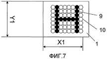
фиг.7 - схематичное изображение третьего воплощения изобретения, где краска наносится на точки к плоскому или гладкому слою 1, который находится в первом состоянии;7 is a schematic illustration of a third embodiment of the invention, where the paint is applied to the points to a flat or
фиг.8 - схематичное изображение слоя в соответствии с фиг.7 во втором состоянии;Fig.8 is a schematic illustration of a layer in accordance with Fig.7 in a second state;
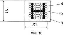
фиг.9 - схематичное изображение четвертого воплощения изобретения, где краска наносится на точки к плоскому или гладкому слою, который находится во втором состоянии, иFig.9 is a schematic representation of a fourth embodiment of the invention, where the paint is applied to the points to a flat or smooth layer, which is in the second state, and
фиг.10 - схематичное изображение слоя в соответствии с фиг.9 в первом состоянии.figure 10 is a schematic illustration of a layer in accordance with figure 9 in a first state.
ПРЕДПОЧТИТЕЛЬНЫЕ ВОПЛОЩЕНИЯ ИЗОБРЕТЕНИЯPREFERRED EMBODIMENTS OF THE INVENTION
Во всех воплощениях, описанных ниже, Х2 обозначает расстояние, которое больше расстояния Х1, а Y2 - расстояние, которое больше Y1.In all of the embodiments described below, X2 is a distance that is greater than the distance X1, and Y2 is a distance that is greater than Y1.
На фиг.1 показано первое воплощение изобретения, где слой 1 с изображением длиной Х1 (направление Х) и шириной Y1 (направление Y) находится в первом состоянии. Здесь изображение состоит из нескольких отдельных черных точек 9, которые совместно образуют букву Н. На фиг.1 слой 1 находится в стянутом состоянии, в котором он собран в складки. Поэтому на фиг.1 показан слой 1 в сморщенном первом состоянии. Тот факт, что этот слой собран в складки, показан на фиг.1 волнообразным узором 3. Слой может складываться в направлении Х, в направлении Y или и в направлении Х, и в направлении Y. Сморщенный слой 1 имеет выступы и углубления между ними. На фиг.1 точки 9 были образованы краской, нанесенной на точки к слою таким образом, чтобы несколько волнообразных выступов были окрашены, когда слой 1 находится в сморщенном состоянии. Это будет объяснено более подробно в связи с фиг.2.1 shows a first embodiment of the invention, where a
На фиг.2 показан увеличенный участок части слоя 1 в соответствии с фиг.1, видимый на сечении А-А на фиг.1. На фиг.2 показано, что краска была нанесена на верхушки 5 выступов 4 на одной стороне слоя. Окрашенные верхушки 5 образуют реальные микроточки 2, которые в первом состоянии совместно образуют точки 9, образующие в свою очередь изображение Н. На фиг.2 можно видеть, что углубления 6 не были окрашены. Окрашивание выступов 4 может быть выполнено, например, распылением краски на выступы 4, когда слой 1 находится в первом состоянии.Figure 2 shows an enlarged portion of a portion of the
На фиг.3 показан слой 1 в соответствии с фиг.1 и фиг.2, где слой 1 был расширен во второе состояние при длине Х2 и ширине Y2, где Х2 больше Х1 и Y2 больше Y1. На фиг.3 показано, что слой 1 находится в гладком состоянии, т.е. где сморщенные части на фиг.1, так сказать, сглажены, в результате чего точки 9 распадаются с образованием размытого изображения, которое может интерпретироваться, как нечеткая и размытая буква Н, где точки 9 распались на целый ряд отдельных серых пятен 7 с промежутками между ними. Пятна 7 также размыты из-за того, что они состоят из целого ряда черных точек 8, которые первоначально были образованы окрашенными верхушками 5, т.е., так сказать, микроточками.Figure 3 shows the
На фиг.3 показано, что пятна 7 являются овальными, вытянутыми в направлении Х. Пятна 7 являются овальными, потому что слой расширялся больше в направлении Х, чем в направлении Y. Изображение Н поэтому распадается самым различным образом, так как слой 1 расширялся по разному в различных направлениях, но независимо от того, как расширяется слой 1, распадение изображения Н происходит таким образом, что изображение Н, показанное на фиг.1, становится более размытым для наблюдателя во втором состоянии, показанном на фиг.3.Figure 3 shows that the
Как можно видеть на фиг.3, размытое изображение находится во втором состоянии, воспринимаемом зрителем как серые пятна 7 с промежутками между ними. С другой стороны, на фиг.1 слой 1 находится в стянутом первом состоянии, при этом окрашенные верхушки 5 расположены с промежутками между ними, из-за чего наблюдатель на таком же расстоянии, как и наблюдатель на фиг.3, воспринимает, что окрашенные верхушки 5, т.е. микроточки 2, сходятся с образованием черных точек 9, которые в свою очередь сходятся таким образом, что появляется изображение в виде Н. Из-за этого возникает изображение, т.е. окрашенные верхушки 5 (микроточки 2) и поэтому также черные точки 9, имеющие более высокую поверхностную плотность в первом состоянии, чем во втором состоянии.As can be seen in figure 3, the blurred image is in the second state, perceived by the viewer as
На фиг.4 показано второе воплощение изобретения, где краска наносится на точки к слою 1, который находится во втором состоянии, т.е., так сказать, в расширенном состоянии, где этот слой имеет длину Х2 и ширину Y2. Краска наносится в виде отдельных точек 9. Во втором состоянии точки 9 расположены с такими промежутками между ними, при которых изображение Н воспринимается наблюдателем, как размытое и нечеткое. На фиг.4 показано, кроме того, что слой был штампован оттисками 10 в виде точечного изображения, где только несколько точечных оттисков 10 были окрашены для образования точек 9. Точечные оттиски 10 могут образовывать трехмерное изображение в слое, но могут также образовывать связывающие точки между двумя слоями. Точечные оттиски 10 могут быть получены, например, пропусканием одного или больше слоев между штампующим валиком и расположенным против него ультразвуковым устройством или расположенным против него валиком с противодавлением. PCT SE03/01959 указывает на предпочтительный способ соединения двух слоев посредством формирования связывающих точек одновременно с окрашиванием по меньшей мере частей связывающих точек. Здесь отдельные точки формируются выбранными частями штампующего валика, окрашенными таким образом, что эти окрашенные части образуют окрашенные отдельные точки 9.Figure 4 shows a second embodiment of the invention, where the paint is applied to the dots to the
На фиг.5 показан слой 1 в соответствии с фиг.4 в первом состоянии, т.е. когда слой сжимается до длины Х1 и ширины Y1. На фиг.5 показано посредством волнистого узора, что слой собран в складки в первом состоянии, при этом он имеет выступы и углубления.Fig. 5 shows a
На фиг.6 показан увеличенный участок части фиг.5 на сечении В-В, где точки 9 расположены как на выступах 11, так и в углублениях 12. Это означает, что изображение Н на фиг.5 кажется четким для наблюдателя, когда слой находится в стянутом первом состоянии из-за того, что промежутки между точками 9 являются такими малыми для наблюдателя, что точки сближаются и образуют изображение Н. Здесь первое состояние может означать состояние слоя, когда и окрашенные выступы 11, и окрашенные углубления 12 являются видимыми таким образом, что для наблюдателя точки 9 достаточно сближаются и изображение Н на фиг.5 становится ясно видимым.FIG. 6 shows an enlarged portion of the portion of FIG. 5 in section BB, where
Во втором воплощении, описанном в связи с фиг.4-6, изображение, т.е., так сказать, черные точки 9, имеет более высокую поверхностную плотность в первом состоянии, чем во втором состоянии, что дает требуемый эффект с ясно видимым изображением в первом состоянии, и слабое и размытое изображение во втором состоянии, когда изображение было нарушено.In the second embodiment described in connection with FIGS. 4-6, the image, i.e., the
На фиг.7 показано третье воплощение изобретения, когда краска наносится на точки к плоскому или гладкому слою 1, который находится в первом состоянии, т.е., так сказать, в сжатом состоянии, где слой 1 имеет длину Х1 и ширину Y1. Краска наносится в виде отдельных точек 9. В первом состоянии изображение Н кажется четким для наблюдателя из-за того, что промежутки между точками 9 настолько малы, что для наблюдателя точки сходятся и образуют изображение Н. На фиг.7 показано, что слой 1, как и слой на фиг.4, был штампован оттисками 10 в виде точечного изображения, где только несколько точечных оттисков 10 были окрашены. Здесь также точечные оттиски 10 могут образовать трехмерное изображение в слое, но могут также образовать связывающие точки между двумя слоями.7 shows a third embodiment of the invention when the paint is applied to the points to a flat or
На фиг.8 показан слой 1 в соответствии с фиг.7 во втором состоянии, т.е., так сказать, когда слой имеет длину Х2 и ширину Y2. Во втором состоянии точки 9 расположены с такими промежутками между ними, что изображение Н воспринимается наблюдателем, как размытое и нечеткое.Fig. 8 shows a
В третьем воплощении, описанном в связи с фиг.7 и фиг.8, изображение, т.е., так сказать, черные точки 9, имеет более высокую поверхностную плотность в первом состоянии, чем во втором состоянии, что дает требуемый эффект с четко видимым изображением в первом состоянии и слабое и размытое изображение во втором состоянии, когда изображение было нарушено. Во втором состоянии точки могли распадаться и поэтому изображение может нарушаться из-за распадения точек. Вариантом является, когда точки образуют связывающие точки, которые не расширяются. Когда слой расширяется из первого состояния во второе состояние, точки поэтому не расширяются, а расширяется только материал между точками, что обеспечивает увеличенные промежутки между точками 9 во втором состоянии.In the third embodiment described in connection with FIG. 7 and FIG. 8, the image, i.e., the
На фиг.9 показано четвертое воплощение изобретения, где краска наносится на точки к плоскому или гладкому слою 1, который находится во втором состоянии, т.е., так сказать, в расширенном состоянии, где слой имеет длину Х2 и ширину Y2. Краска наносится в виде отдельных точек 9. Во втором состоянии точки 9 расположены с такими промежутками между ними, что изображение воспринимается наблюдателем, как размытое и нечеткое. На фиг.9 показано, как на фиг.4 и на фиг.7, что слой штамповался оттисками 10 в виде точечного изображения, где только несколько точечных оттисков было окрашено.Fig. 9 shows a fourth embodiment of the invention, where the paint is applied to the dots to a flat or
На фиг.10 показан слой 1 в соответствии с фиг.9 в первом состоянии, т.е., так сказать, когда слой имеет длину Х1 и ширину Y1. В первом состоянии изображение Н кажется четким для наблюдателя по причине того, что промежутки между точками 9 настолько малы, что для наблюдателя эти точки сходятся вместе с образованием изображения Н.FIG. 10 shows a
В четвертом воплощении, описанном в связи с фиг.8 и 9, изображение, т.е., так сказать, черные точки 9, имеют более высокую поверхностную плотность в первом состоянии, чем во втором состоянии, что вызывает требуемый эффект с четко видимым изображением в первом состоянии и нарушение изображения во втором состоянии со слабым и размытым изображением во втором состоянии.In the fourth embodiment described in connection with FIGS. 8 and 9, the image, i.e., the
Штампование, указанное на фиг.4-10, может быть заменено только точечным окрашиванием слоя; такой же результат в отношении четкости изображения Н в первом состоянии и во втором состоянии достигается так, как рассмотрено выше в связи с фиг.4-10.The stamping indicated in FIGS. 4-10 can only be replaced by spot staining of the layer; the same result with respect to the image sharpness H in the first state and in the second state is achieved as discussed above in connection with FIGS. 4-10.
Во всех воплощениях слой предпочтительно состоит из упругого материала или из неупругого материала, содержащего упругое средство, например, эластичные ленты или нити.In all embodiments, the layer preferably consists of an elastic material or of an inelastic material containing an elastic means, for example, elastic tapes or threads.
Claims (10)
Translated fromRussianApplications Claiming Priority (2)
| Application Number | Priority Date | Filing Date | Title |
|---|---|---|---|
| SE0303505-2 | 2003-12-22 | ||
| SE0303505ASE0303505D0 (en) | 2003-12-22 | 2003-12-22 | Patterned layer on absorbent articles |
Publications (2)
| Publication Number | Publication Date |
|---|---|
| RU2006122260A RU2006122260A (en) | 2008-01-10 |
| RU2350707C2true RU2350707C2 (en) | 2009-03-27 |
Family
ID=30768824
Family Applications (1)
| Application Number | Title | Priority Date | Filing Date |
|---|---|---|---|
| RU2006122260/12ARU2350707C2 (en) | 2003-12-22 | 2004-12-22 | Layer with image for absorbent fabrics |
Country Status (7)
| Country | Link |
|---|---|
| EP (1) | EP1697588B1 (en) |
| CN (1) | CN100497814C (en) |
| AT (1) | ATE544907T1 (en) |
| BR (1) | BRPI0418027B1 (en) |
| RU (1) | RU2350707C2 (en) |
| SE (1) | SE0303505D0 (en) |
| WO (1) | WO2005061795A1 (en) |
Cited By (1)
| Publication number | Priority date | Publication date | Assignee | Title |
|---|---|---|---|---|
| RU2569589C1 (en)* | 2011-10-05 | 2015-11-27 | Ска Хайджин Продактс Аб | Method of application of structural elements of absorbent article |
Citations (6)
| Publication number | Priority date | Publication date | Assignee | Title |
|---|---|---|---|---|
| FR2541872A3 (en)* | 1983-03-03 | 1984-09-07 | Espanola Ortopedica | Improved nappy |
| RU2109500C1 (en)* | 1992-12-01 | 1998-04-27 | КонваТек Лимитед | Flexible bandage |
| US5897541A (en)* | 1994-09-30 | 1999-04-27 | Kimberly-Clark Worldwide, Inc. | Laminate material and absorbent garment comprising same |
| RU11983U1 (en)* | 1999-07-09 | 1999-12-16 | Шрамков Вячеслав Сергеевич | TOILET PAPER |
| WO2000076439A2 (en)* | 1999-06-15 | 2000-12-21 | Kimberly-Clark Worldwide, Inc. | Absorbent articles having wetness indicating graphics incorporating a training zone |
| GB2360250A (en)* | 2000-03-17 | 2001-09-19 | Arc Screen Print Ltd | Printing whereby different images are discernable at different angles of view |
Family Cites Families (6)
| Publication number | Priority date | Publication date | Assignee | Title |
|---|---|---|---|---|
| DE3640979A1 (en)* | 1986-02-26 | 1987-08-27 | Rauscher & Co | Permanently elastic bandage |
| CN2250925Y (en)* | 1996-08-22 | 1997-04-02 | 珠海市中富工业集团公司 | Packaging film with identification mark in packaging pattern layer |
| AU740715B2 (en) | 1997-05-08 | 2001-11-15 | Ethicon Inc. | Bandage compression indicator |
| DE10037113A1 (en) | 2000-07-27 | 2002-03-07 | Sandor Potak | Elastic exercise appliance has patterned surface differing in shape between expanded and non-expanded states. |
| DE10043217B4 (en)* | 2000-09-01 | 2005-06-02 | Papcel - Papier Und Cellulose, Technologie Und Handels-Gmbh | Filter material and filter bags and filter bags made of this material |
| US20030044578A1 (en)* | 2001-08-14 | 2003-03-06 | Nissing Nicholas James | Printed substrate with variable local attributes |
- 2003
- 2003-12-22SESE0303505Apatent/SE0303505D0/enunknown
- 2004
- 2004-12-22WOPCT/SE2004/001961patent/WO2005061795A1/ennot_activeApplication Discontinuation
- 2004-12-22ATAT04809134Tpatent/ATE544907T1/enactive
- 2004-12-22RURU2006122260/12Apatent/RU2350707C2/enactive
- 2004-12-22BRBRPI0418027Apatent/BRPI0418027B1/ennot_activeIP Right Cessation
- 2004-12-22CNCNB2004800385390Apatent/CN100497814C/ennot_activeExpired - Fee Related
- 2004-12-22EPEP04809134Apatent/EP1697588B1/ennot_activeExpired - Lifetime
Patent Citations (6)
| Publication number | Priority date | Publication date | Assignee | Title |
|---|---|---|---|---|
| FR2541872A3 (en)* | 1983-03-03 | 1984-09-07 | Espanola Ortopedica | Improved nappy |
| RU2109500C1 (en)* | 1992-12-01 | 1998-04-27 | КонваТек Лимитед | Flexible bandage |
| US5897541A (en)* | 1994-09-30 | 1999-04-27 | Kimberly-Clark Worldwide, Inc. | Laminate material and absorbent garment comprising same |
| WO2000076439A2 (en)* | 1999-06-15 | 2000-12-21 | Kimberly-Clark Worldwide, Inc. | Absorbent articles having wetness indicating graphics incorporating a training zone |
| RU11983U1 (en)* | 1999-07-09 | 1999-12-16 | Шрамков Вячеслав Сергеевич | TOILET PAPER |
| GB2360250A (en)* | 2000-03-17 | 2001-09-19 | Arc Screen Print Ltd | Printing whereby different images are discernable at different angles of view |
Cited By (1)
| Publication number | Priority date | Publication date | Assignee | Title |
|---|---|---|---|---|
| RU2569589C1 (en)* | 2011-10-05 | 2015-11-27 | Ска Хайджин Продактс Аб | Method of application of structural elements of absorbent article |
Also Published As
| Publication number | Publication date |
|---|---|
| CN1898440A (en) | 2007-01-17 |
| SE0303505D0 (en) | 2003-12-22 |
| EP1697588A1 (en) | 2006-09-06 |
| RU2006122260A (en) | 2008-01-10 |
| CN100497814C (en) | 2009-06-10 |
| WO2005061795A1 (en) | 2005-07-07 |
| ATE544907T1 (en) | 2012-02-15 |
| BRPI0418027B1 (en) | 2015-09-15 |
| EP1697588B1 (en) | 2012-02-08 |
| BRPI0418027A (en) | 2007-04-17 |
Similar Documents
| Publication | Publication Date | Title |
|---|---|---|
| US8821980B2 (en) | Method of making a patterned layer for absorbent article | |
| DE69600015T2 (en) | Nasal dilator | |
| DE19832990B4 (en) | Label and method for concealing information | |
| CA2688609C (en) | Vision control panel assembly with a contrasting colored liner | |
| US6966971B1 (en) | Absorbent wipe having bonding material logo | |
| RU2350707C2 (en) | Layer with image for absorbent fabrics | |
| US6651551B1 (en) | Printable absorbent surface having permanent image and disappearing image | |
| JP2004130053A (en) | Tissue paper containing figure and laminated paper using the same | |
| DE102010060316A1 (en) | A message-carrying medium with a hidden message | |
| JP4429657B2 (en) | label | |
| DE69614704T2 (en) | DEVICE FOR FORMING AN IMAGE EDGE | |
| US20090249666A1 (en) | Method of and system for two-way see-through banner and window imaging | |
| JP2000318327A (en) | Thermosensitive printed matter and method for producing the same | |
| DE29815584U1 (en) | Wine bottle with label element | |
| De Weert | Assimilation versus contrast | |
| EP1738008B1 (en) | Flat sheet for receiving a printed pattern, process for producing same, and use thereof | |
| JP3767911B2 (en) | Special printed matter | |
| EP2886617B1 (en) | Reflecting product | |
| EP0977166A2 (en) | Label | |
| EP2638536A1 (en) | Textile | |
| JP6895739B2 (en) | Printed matter | |
| JP3008452U (en) | Copy forgery protection paper | |
| US20060242749A1 (en) | Mask apparatus | |
| DE10138068C2 (en) | Process for producing a transparent printed product on a transparent carrier material | |
| JP3024580U (en) | In-car hanging advertisement |
Legal Events
| Date | Code | Title | Description |
|---|---|---|---|
| PD4A | Correction of name of patent owner |