RU2348787C2 - Instrument for boring object - Google Patents
Instrument for boring objectDownload PDFInfo
- Publication number
- RU2348787C2 RU2348787C2RU2006103800/03ARU2006103800ARU2348787C2RU 2348787 C2RU2348787 C2RU 2348787C2RU 2006103800/03 ARU2006103800/03 ARU 2006103800/03ARU 2006103800 ARU2006103800 ARU 2006103800ARU 2348787 C2RU2348787 C2RU 2348787C2
- Authority
- RU
- Russia
- Prior art keywords
- abrasive particles
- inlet
- magnet
- inlet opening
- supporting surface
- Prior art date
Links
Images


Classifications
- E—FIXED CONSTRUCTIONS
- E21—EARTH OR ROCK DRILLING; MINING
- E21B—EARTH OR ROCK DRILLING; OBTAINING OIL, GAS, WATER, SOLUBLE OR MELTABLE MATERIALS OR A SLURRY OF MINERALS FROM WELLS
- E21B7/00—Special methods or apparatus for drilling
- E21B7/18—Drilling by liquid or gas jets, with or without entrained pellets
- B—PERFORMING OPERATIONS; TRANSPORTING
- B03—SEPARATION OF SOLID MATERIALS USING LIQUIDS OR USING PNEUMATIC TABLES OR JIGS; MAGNETIC OR ELECTROSTATIC SEPARATION OF SOLID MATERIALS FROM SOLID MATERIALS OR FLUIDS; SEPARATION BY HIGH-VOLTAGE ELECTRIC FIELDS
- B03C—MAGNETIC OR ELECTROSTATIC SEPARATION OF SOLID MATERIALS FROM SOLID MATERIALS OR FLUIDS; SEPARATION BY HIGH-VOLTAGE ELECTRIC FIELDS
- B03C1/00—Magnetic separation
- B03C1/02—Magnetic separation acting directly on the substance being separated
- B03C1/025—High gradient magnetic separators
- B03C1/031—Component parts; Auxiliary operations
- B03C1/033—Component parts; Auxiliary operations characterised by the magnetic circuit
- B03C1/0332—Component parts; Auxiliary operations characterised by the magnetic circuit using permanent magnets
- B—PERFORMING OPERATIONS; TRANSPORTING
- B03—SEPARATION OF SOLID MATERIALS USING LIQUIDS OR USING PNEUMATIC TABLES OR JIGS; MAGNETIC OR ELECTROSTATIC SEPARATION OF SOLID MATERIALS FROM SOLID MATERIALS OR FLUIDS; SEPARATION BY HIGH-VOLTAGE ELECTRIC FIELDS
- B03C—MAGNETIC OR ELECTROSTATIC SEPARATION OF SOLID MATERIALS FROM SOLID MATERIALS OR FLUIDS; SEPARATION BY HIGH-VOLTAGE ELECTRIC FIELDS
- B03C1/00—Magnetic separation
- B03C1/02—Magnetic separation acting directly on the substance being separated
- B03C1/10—Magnetic separation acting directly on the substance being separated with cylindrical material carriers
- B03C1/14—Magnetic separation acting directly on the substance being separated with cylindrical material carriers with non-movable magnets
- B—PERFORMING OPERATIONS; TRANSPORTING
- B24—GRINDING; POLISHING
- B24C—ABRASIVE OR RELATED BLASTING WITH PARTICULATE MATERIAL
- B24C11/00—Selection of abrasive materials or additives for abrasive blasts
- B—PERFORMING OPERATIONS; TRANSPORTING
- B24—GRINDING; POLISHING
- B24C—ABRASIVE OR RELATED BLASTING WITH PARTICULATE MATERIAL
- B24C9/00—Appurtenances of abrasive blasting machines or devices, e.g. working chambers, arrangements for handling used abrasive material
- B24C9/006—Treatment of used abrasive material
- Y—GENERAL TAGGING OF NEW TECHNOLOGICAL DEVELOPMENTS; GENERAL TAGGING OF CROSS-SECTIONAL TECHNOLOGIES SPANNING OVER SEVERAL SECTIONS OF THE IPC; TECHNICAL SUBJECTS COVERED BY FORMER USPC CROSS-REFERENCE ART COLLECTIONS [XRACs] AND DIGESTS
- Y02—TECHNOLOGIES OR APPLICATIONS FOR MITIGATION OR ADAPTATION AGAINST CLIMATE CHANGE
- Y02P—CLIMATE CHANGE MITIGATION TECHNOLOGIES IN THE PRODUCTION OR PROCESSING OF GOODS
- Y02P70/00—Climate change mitigation technologies in the production process for final industrial or consumer products
- Y02P70/10—Greenhouse gas [GHG] capture, material saving, heat recovery or other energy efficient measures, e.g. motor control, characterised by manufacturing processes, e.g. for rolling metal or metal working
Landscapes
- Engineering & Computer Science (AREA)
- Geology (AREA)
- Mechanical Engineering (AREA)
- Life Sciences & Earth Sciences (AREA)
- Mining & Mineral Resources (AREA)
- General Life Sciences & Earth Sciences (AREA)
- Fluid Mechanics (AREA)
- Environmental & Geological Engineering (AREA)
- Physics & Mathematics (AREA)
- Geochemistry & Mineralogy (AREA)
- Grinding-Machine Dressing And Accessory Apparatuses (AREA)
- Earth Drilling (AREA)
- Processing Of Stones Or Stones Resemblance Materials (AREA)
- Perforating, Stamping-Out Or Severing By Means Other Than Cutting (AREA)
- Pharmaceuticals Containing Other Organic And Inorganic Compounds (AREA)
- Manipulator (AREA)
Abstract
Description
Translated fromRussianОписаниеDescription
Настоящее изобретение относится к инструменту для проходки объекта, содержащему гидромониторную систему, имеющую сопловое средство, предназначенное для приема текучей среды и абразивных частиц через впускное отверстие для абразивных частиц и вторжения выпуска струей потока текучей среды, смешанной с абразивными частицами, в проходимый объект.The present invention relates to a tool for driving an object, comprising a hydromonitor system having nozzle means for receiving fluid and abrasive particles through an inlet for abrasive particles and intruding an outlet of a fluid stream mixed with abrasive particles into a passable object.
Такой инструмент в типичном случае может быть расположен на нижнем конце бурильной колонны, которая развернута в стволе подземной скважины, вследствие чего во время работы текучая среда закачивается в виде бурового раствора с поверхности по продольному каналу в бурильной колонне в инструмент и, по существу, обратно на поверхность в возвратном потоке по кольцевому пространству между бурильной колонной и стенкой ствола скважины. Для предотвращения непрерывной циркуляции абразивных частиц по бурильной колонне и кольцевому пространству в патенте США №6510907 предложено разработать инструмент с рециркуляционной системой для отделения абразивных частиц от возвратного потока и повторного введения этих частиц в гидромониторную систему.Such a tool can typically be located at the lower end of the drill string, which is deployed in the borehole of the subterranean well, whereby during operation, fluid is pumped in the form of drilling fluid from the surface along the longitudinal channel in the drill string into the tool and, essentially, back to surface in the return flow along the annular space between the drill string and the wall of the wellbore. To prevent the continuous circulation of abrasive particles through the drill string and annular space in US patent No. 6510907 proposed to develop a tool with a recirculation system for separating abrasive particles from the return flow and re-introduction of these particles in the hydraulic monitoring system.
Еще один такой инструмент описан в международной публикации WO 02/34563. Рециркуляционная система основана на спиральном магните сепаратора, который расположен концентрично внутри опорного элемента. Опорный элемент образован цилиндрической гильзой, внешняя поверхность которой образует опорную поверхность, на которой магнитное поле, создаваемое спиральным магнитом сепаратора, удерживает магнитные частицы. Спиральный магнит сепаратора имеет продольную ось, вокруг которой магнит сепаратора вращается относительно гильзы.Another such tool is described in international publication WO 02/34563. The recirculation system is based on a spiral magnet of the separator, which is located concentrically inside the support element. The support element is formed by a cylindrical sleeve, the outer surface of which forms a support surface, on which the magnetic field created by the spiral magnet of the separator, holds the magnetic particles. The spiral magnet of the separator has a longitudinal axis around which the separator magnet rotates relative to the sleeve.
Когда магниту сепаратора сообщается осевое вращение, магнитные частицы подвергаются воздействию движущего градиента напряженности магнитного поля, перпендикулярного спиральной канавке, по которой будут следовать эти частицы. Таким образом, частицы переносятся по опорной поверхности обратно в гидромониторную систему с целью повторного введения.When axial rotation is reported to the separator magnet, the magnetic particles are exposed to a moving gradient of magnetic field strength perpendicular to the spiral groove along which these particles will follow. Thus, the particles are transferred along the abutment surface back into the hydraulic monitoring system for the purpose of reintroduction.
Оба известных инструмента основаны на эффективном перемещении абразивных частиц от магнита сепаратора к гидромониторной системе. Это важно, в частности, когда нужно осуществлять рециркуляцию большого количества абразивных частиц в единицу времени, потому что в таком случае скопление абразивных частиц может вызывать закупоривание впускного отверстия для абразивных частиц, имеющегося в гидромониторной системе. Скопления абразивных частиц увеличиваются их магнитными взаимодействиями.Both well-known tools are based on the effective movement of abrasive particles from the separator magnet to the hydraulic monitor system. This is important, in particular, when it is necessary to recycle a large number of abrasive particles per unit time, because in this case, the accumulation of abrasive particles can cause clogging of the inlet for abrasive particles present in the hydraulic monitor system. Accumulations of abrasive particles are increased by their magnetic interactions.
Кроме того, возвратный поток, из которого нужно выделять абразивные частицы, обычно содержит также обломки проходимой породы, которые могут включать отдельные частицы породы, которые больше проема, через который происходит доступ во впускное отверстие для абразивных частиц, ведущее в гидромониторную систему. Такие частицы могут заблокировать впускное отверстие для абразивных частиц, имеющееся в гидромониторной системе, и тем самым затруднить процесс рециркуляции абразивных частиц.In addition, the return flow from which the abrasive particles must be separated out usually also contains fragments of passable rock, which may include individual rock particles that are larger than the opening through which access to the abrasive particle inlet leads to the hydraulic monitoring system. Such particles can block the abrasive particle inlet in the hydraulic monitor system, and thereby impede the process of recycling the abrasive particles.
В соответствии с настоящим изобретением предложен инструмент для проходки объекта, содержащий гидромониторную систему, имеющую сопловое средство, предназначенное для приема текучей среды и абразивных частиц через впускное отверстие для абразивных частиц и вторжения выпускаемого струей потока текучей среды, смешанной с абразивными частицами, в проходимый объект, рециркуляционную систему, выполненную с возможностью рециркуляции, по меньшей мере, некоторых из абразивных частиц из возвратного потока после подачи выпускаемого струей потока в проходимый объект обратно в гидромониторную систему через впускное отверстие для абразивных частиц, причем впускное отверстие для абразивных частиц имеет входной проем, при этом на пути гидравлического сообщения возвратного потока с входным проемом предусмотрено фильтрующее средство, являющееся проходимым для абразивных частиц.In accordance with the present invention, there is provided a tool for driving an object, comprising a hydromonitor system having nozzle means for receiving fluid and abrasive particles through an inlet for abrasive particles and for invading a blown fluid stream mixed with abrasive particles into a passable object, a recirculation system configured to recirculate at least some of the abrasive particles from the return stream after the discharge of the exhaust stream through eye traveled in the object back to the jetting system via the inlet for abrasive particles, with an inlet for abrasive particles has an inlet opening, the fluid communication path to the return stream to the inlet opening is provided filter means which is passable for the abrasive particles.
В таком случае впускное отверстие для абразивных частиц поддерживается свободным от предметов, имеющих такой же размер, как входной проем, или больший, а абразивные частицы при этом могут достигать впускного отверстия для абразивных частиц.In this case, the inlet for abrasive particles is kept free from objects having the same size as the inlet opening or larger, while the abrasive particles can reach the inlet for abrasive particles.
Фильтрующее средство может быть снабжено одним или несколькими фильтрационными отверстиями, форма и расположение которых таковы, что фильтрующее средство непроходимо для частицы, имеющей такие же проекцию, размер и форму, как у входного проема впускного отверстия для абразивных частиц, и полная блокировка одного или нескольких фильтрационных отверстий одной такой частицей невозможна. Таким образом, даже когда одна такая частица застревает в одном или нескольких фильтрационных отверстий, сохраняется возможность переноса через другое отверстие или часть отверстия, которая не блокирована.The filter medium may be provided with one or more filter holes, the shape and location of which is such that the filter medium is impassable for a particle having the same projection, size and shape as the inlet opening of the inlet for abrasive particles, and the complete blocking of one or more filter holes holes with one such particle is impossible. Thus, even when one such particle is stuck in one or more filtering openings, it is possible to transfer through another opening or part of the opening that is not blocked.
Этого можно достичь с помощью фильтрационного отверстия, имеющего относительно большое отношение характеристик размеров и имеющего в одном направлении меньший размер, чем входной проем впускного отверстия для абразивных частиц, а в другом направлении - больший.This can be achieved using a filtration hole having a relatively large ratio of dimensional characteristics and having in one direction a smaller size than the inlet opening of the inlet for abrasive particles, and in the other direction, a larger one.
Общая проходная площадь фильтрационного отверстия в преимущественном варианте выполнения изобретения может быть больше, чем общая проходная площадь входного проема впускного отверстия для абразивных частиц, для минимизации негативного влияния фильтрующего средства на рециркуляцию абразивных частиц.The total passage area of the filtration hole in an advantageous embodiment of the invention may be larger than the total passage area of the inlet opening of the inlet for abrasive particles, in order to minimize the negative effect of the filter medium on the recirculation of the abrasive particles.
В преимущественном варианте осуществления, в котором рециркуляционная система содержит опорную поверхность для направления абразивных частиц во впускное отверстие для абразивных частиц, фильтрующее средство выполнено в виде юбки, создающей фильтрационное отверстие в форме щели между юбкой и опорной поверхностью.In an advantageous embodiment, in which the recirculation system comprises a support surface for guiding the abrasive particles into the abrasive particle inlet, the filtering means is made in the form of a skirt creating a filtering hole in the form of a gap between the skirt and the supporting surface.
Такая юбка вокруг опорной поверхности направляет поток бурового раствора из кольцевого пространства ствола скважины во впускное отверстие для абразивных частиц по опорной поверхности, тем самым дополнительно поддерживая перемещение абразивных частиц по опорной поверхности во впускное отверстие для абразивных частиц и в гидромониторную систему.Such a skirt around the abutment surface directs the flow of drilling fluid from the annular space of the wellbore into the abrasive particle inlet over the abutment surface, thereby further supporting the movement of abrasive particles along the abutment surface into the abrasive particle inlet and into the hydraulic monitoring system.
Далее изобретение будет проиллюстрировано на примере со ссылками на прилагаемые чертежи, схематически иллюстрирующие его, на которых изображено следующее:The invention will now be illustrated by way of example with reference to the accompanying drawings, schematically illustrating it, which depict the following:
Фиг.1 представляет продольное сечение, выполненное вдоль линии В-В, части инструмента для проходки объекта;Figure 1 is a longitudinal section taken along the line BB, part of the tool for driving the object;
Фиг.2 представляет вид инструмента согласно фиг.1, иллюстрирующий фильтрующее средство в форме юбки;FIG. 2 is a view of the tool of FIG. 1 illustrating skirt-shaped filtering means; FIG.
Фиг.3 представляет поперечное сечение, выполненное вдоль линии А-А, впускного отверстия для абразивных частиц;Figure 3 is a cross-section taken along line AA of the inlet for abrasive particles;
Фиг.4 представляет карту возможной компоновки поверхности магнита для инструмента согласно фиг.1;Figure 4 is a map of a possible arrangement of the surface of the magnet for the tool according to figure 1;
Фиг.5а, 5в, 5с представляют альтернативные компоновки магнита для использования в инструменте.Figures 5a, 5c, 5c show alternative magnet arrangements for use in an instrument.
На чертежах одинаковые детали обозначены идентичными позициями. В тех местах нижеследующего описания, где речь идет о направлении вращения, направление перемещения каждый раз является направлением визирования, относительно которого определяется направление вращения.In the drawings, like parts are denoted by identical numbers. In those places of the following description, where it is a direction of rotation, the direction of movement each time is the direction of sight, relative to which the direction of rotation is determined.
Часть инструмента для проходки объекта схематически показана в продольном сечении на фиг.1. Этот инструмент может быть подсоединен к нижнему концу бурильной колонны (не показана), проходящей в ствол скважины, сформированный в объекте, таком как пласт породы. Инструмент выполнен с возможностью выпускать струей поток бурового раствора, смешанный с абразивными частицами, к объекту, который надо пройти, и с возможностью рециркуляции, по меньшей мере, части абразивных частиц.Part of the tool for driving the object is schematically shown in longitudinal section in figure 1. This tool can be connected to the lower end of a drill string (not shown) extending into a wellbore formed in an object, such as a formation. The tool is configured to jet a drilling fluid stream mixed with abrasive particles to an object to be passed and to recycle at least a portion of the abrasive particles.
Инструмент снабжен продольным каналом 1 для бурового раствора, который на одном своем конце гидравлически сообщается с каналом бурового раствора, предусмотренным в бурильной колонне, а на другом своем конце гидравлически сообщается с гидромониторной системой, имеющей сопловое средство. Сопловое средство содержит смесительную камеру 2, которая соединена c каналом 1 для бурового раствора посредством впускного отверстия 3 для бурового раствора.The tool is provided with a longitudinal channel 1 for the drilling fluid, which at one end is hydraulically connected to the channel of the drilling fluid provided in the drill string, and at its other end is hydraulically connected to the hydraulic monitoring system having nozzle means. The nozzle means comprises a
Смесительная камера 2 также гидравлически сообщается с впускным отверстием 4 для абразивных частиц, предназначенным для введения абразивных частиц, и со смесительным соплом 5, имеющим выпускное отверстие (не показано), предназначенное для выпуска струей потока бурового раствора и абразивных частиц к пласту породы во время бурения с помощью бурового раствора, находящегося в стволе скважины.The
Смесительная камера 2 снабжена элементом 14 из магнитного материала на стороне, противоположной впускному отверстию 4 для абразивных частиц, но это необязательно.The
Смесительное сопло 5 расположено с наклоном относительно продольного направления бурового инструмента, при этом угол наклона относительно вертикали составляет 15-30°, но можно использовать и другие углы. Угол наклона предпочтительно составляет примерно 21°, и это значение оптимально для абразивной эрозии забоя ствола скважины за счет осевого вращения всего инструмента внутри ствола скважины. Смесительная камера 2 и смесительное сопло 5 ориентированы под одинаковым углом относительно выпускного сопла, чтобы достичь оптимального ускорения абразивных частиц.The mixing
Канал 1 для бурового раствора расположен так, что он обходит транспортирующее устройство 6 для перемещения абразивных частиц, которое включено в состав инструмента как часть рециркуляционной системы для магнитных абразивных частиц и которое может быть использовано, если абразивные частицы содержат магнитный материал. Устройство 6 включает опорный элемент в форме гильзы 15 с небольшой конусностью для обеспечения опорной поверхности, проходящей вокруг удлиненного магнита 7 сепаратора, имеющего, по существу, цилиндрическую форму. Магнит 7 сепаратора создает магнитное поле для удержания магнитных частиц на опорной поверхности 15.The drilling fluid channel 1 is positioned so that it bypasses the abrasive particle transport device 6, which is included in the tool as part of a magnetic abrasive particle recirculation system and which can be used if the abrasive particles contain magnetic material. The device 6 includes a support element in the form of a
Канал 1 для бурового раствора расположен неподвижно относительно опорной поверхности 15 и смесительной камеры 2. Канал 1 для бурового раствора имеет нижний конец, расположенный около впускного отверстия 4 для абразивных частиц. В данном варианте осуществления канал 1 для бурового раствора выполнен внутри гребня в осевом направлении, который, выступая, находится в контакте с опорной поверхностью 15. В альтернативном варианте канал 1 для бурового раствора может быть выполнен автономным от опорной поверхности аналогично тому, который описан в международной публикации WO 02/34653 и проиллюстрирован на фиг.4 этой публикации, или в направлении, не являющемся осевым. Впускное отверстие 4 для абразивных частиц находится у нижнего конца гребня.The drilling fluid channel 1 is stationary relative to the
Опорная поверхность 15 имеет коническую форму. В альтернативном варианте опорная поверхность может быть цилиндрической.The supporting
Цилиндрический магнит 7 сепаратора образован из четырех меньших магнитов 7а, 7b, 7с и 7d, уложенных стопой друг на друга. Можно также использовать другое количество меньших магнитов. Каждый магнит 7а, 7b, 7с и 7d имеет диаметрально противоположные полюсы N и S, и эти магниты уложены стопой таким образом, что соседние магниты имеют направления N-S, азимутально повернутые друг относительно друга вокруг центральной продольной оси 8 на угол φ, вследствие чего каждое чередование N- и S-полюсов приводит к получению двух, по существу, спиральных, диаметрально противоположных полос.The cylindrical magnet 7 of the separator is formed of four
В контексте этого описания магнитный полюс - это область на поверхности магнита или на опорной поверхности, где силовые линии магнитного поля пересекают поверхность магнита или опорную поверхность, и поэтому она является областью истока или стока силовых линий магнитного поля.In the context of this description, the magnetic pole is a region on the surface of the magnet or on the supporting surface where the magnetic field lines intersect the magnet surface or the supporting surface, and therefore it is the source or drain region of the magnetic field lines.
Из-за природы двухполюсного магнита напряженность магнитного поля в областях между N- и S-полюсами в каждом из меньших магнитов 7а, 7b, 7с и 7d меньше, чем в областях вокруг N- и S-полюсами, ориентированных, по существу, спирально. Таким образом, спиральные полосы чередующихся N- и S-полюсов образуют полосу сильного поля, имеющего повышенную напряженность магнитного поля по сравнению с областями, образующими полосу слабого поля, повернутую примерно на 90° по азимуту относительно полосы сильного поля. В промежутке между полосами сильного и слабого полей имеется зона градиента, где напряженность магнитного поля уменьшается от большего значения в полосе сильного поля до значения в полосе слабого поля.Due to the nature of the bipolar magnet, the magnetic field in the regions between the N- and S-poles in each of the
Магнит 7 сепаратора имеет центральную продольную ось 8 и выполнен с возможностью вращения относительно гильзы 15 и вокруг центральной продольной оси. Предусмотрены средства привода (не показаны), предназначенные для привода оси 8 и тем самым - вращения магнита 7 сепаратора в направлении либо по часовой стрелке, либо против часовой стрелки, что диктуется ориентацией спиральной полосы. В преимущественном варианте средства привода могут быть выполнены в виде электродвигателя, управление которым может осуществлять система управления (не показана).The separator magnet 7 has a central
На нижнем конце магнита 7d предусмотрен короткий конический участок 11. Гильза 15 снабжена соответствующим коническим сужением, так что впускное отверстие для абразивных частиц обеспечивает гидравлическое сообщение между опорной поверхностью 15, окружающей конический участок 11, и смесительной камерой 2. Коническое сужение в наилучшем случае расположено под тем же углом, что и вышеупомянутый угол смесительной камеры 2 и смесительного сопла 5.A short
На фиг.2 представлен схематический вид снаружи инструмента и показаны опорная поверхность 15 конической формы, в пределах которой заключен магнит 7 сепаратора, и гребень 41, в пределах которого заключен обходной канал для бурового раствора. Размеры соответствуют тем, которые приведены в таблице 1.Figure 2 presents a schematic view of the outside of the tool and shows the supporting
Область в окрестности впускного отверстия 4 для абразивных частиц (показанного на фиг.1) защищена щитком в форме юбки 43. Между юбкой 43 и опорной поверхностью 15 оставлен открытый зазор, через который по пути вдоль опорной поверхности 15 возможен доступ к впускному отверстию 4 для абразивных частиц. Этот путь проходит сквозь фильтрационное отверстие в форме щели 44, проходящей между юбкой 43 и опорной поверхностью 15.The area in the vicinity of the abrasive particle inlet 4 (shown in FIG. 1) is protected by a skirt-shaped
На фиг.3 показано поперечное сечение, выполненное вдоль линии А-А, показанной на фиг.1 и 2, через магнит 7d поперек оси 8 и через смесительную камеру 2 и элемент 14 из магнитного материала. Упомянутый зазор проходит между юбкой 43 и опорной поверхностью 15. Доступ в этот зазор возможен через щель 44.Figure 3 shows a cross-section taken along the line aa shown in figures 1 and 2, through a
Отметим, что юбка 43 в инструменте, как показано на фиг.2 и 3, пригодна для использования в сочетании с магнитом сепаратора, вращающимся по часовой стрелке. Должно быть, очевидно, что для инструмента с магнитом сепаратора, вращающимся против часовой стрелки, юбка должна быть расположена на противоположной стороне впускного отверстия для абразивных частиц.Note that the
Если используется элемент 14 из магнитного материала, то он на стороне, противоположной впускному отверстию 4 для абразивных частиц, увлекает часть магнитного поля, создаваемого магнитом сепаратора, в смесительную камеру 2. В результате магнитная сила, притягивающая магнитные частицы 23 к опорной поверхности 15, оказывает меньшее влияние на магнитные частицы, которые попадают в область впускного отверстия 4 для абразивных частиц. Таким образом, попадание магнитных абразивных частиц через впускное отверстие 3 для бурового раствора в смесительную камеру 2 дополнительно облегчается.If an
Во время эксплуатации инструмент работает следующим образом. Инструмент соединен с нижним концом бурильной колонны, которая проходит с поверхности в ствол скважины. Как ясно из фиг.1, поток бурового раствора закачивается с помощью подходящего насоса (не показан), находящегося на поверхности, по каналу бурового раствора в бурильной колонне и каналу 1 бурового раствора в смесительную камеру 2. Во время первоначального закачивания этот поток имеет низкую концентрацию абразивных частиц магнитного материала, таких как стальная дробь или стальные опилки.During operation, the tool operates as follows. The tool is connected to the lower end of the drill string, which extends from the surface into the wellbore. As is clear from FIG. 1, the mud stream is pumped using a suitable pump (not shown) located on the surface through the mud channel in the drill string and mud channel 1 into the mixing
Поток протекает из смесительной камеры 2 в смесительное сопло 5 и выпускается из него в виде струи к забою ствола скважины. Одновременно с этим происходит вращение бурильной колонны, так что забой ствола скважины подвергается равномерной эрозии. Возвратный поток, содержащий текучую среду, абразивные частицы и обломки проходимой породы, течет от забоя ствола скважины по этому стволу скважины в обратном направлении - к поверхности. Таким образом, возвратный поток проходит через гильзу 15.The stream flows from the mixing
Одновременно с закачиванием потока бурового раствора магнит 7 сепаратора вращается вокруг оси 8 в направлении, диктуемом ориентацией спиральных полос, которая может быть либо по часовой стрелке, либо против часовой стрелки. Магнит 7 сепаратора индуцирует магнитное поле, распространяющееся к внешней поверхности гильзы 15 и выходящее за нее. Когда поток проходит вдоль гильзы 15, абразивные частицы, присутствующие в потоке, отделяются от этого потока магнитными силами, прикладываемыми магнитом 7 сепаратора, которые притягивают эти частицы к внешней поверхности гильзы 15.Simultaneously with the injection of the drilling fluid stream, the separator magnet 7 rotates around
Поток бурового раствора, который теперь, по существу, не содержит абразивные магнитные частицы, течет дальше по стволу скважины к насосу на поверхности и рециркулируется по бурильной колонне после удаления бурового шлама.The mud stream, which now essentially does not contain abrasive magnetic particles, flows further down the wellbore to the surface pump and is recycled through the drill string after the drill cuttings have been removed.
Магнитные силы, прикладываемые к абразивным частицам в области слабого поля, меньше, чем в области сильного поля. Магнитные частицы, удерживаемые на опорной поверхности 15, притягиваются к полосе, имеющей наиболее сильное магнитное поле. Ввиду вращения магнита 7 сепаратора в направлении, соответствующем ориентации спиральных полос, соответствующие полосы и зона градиента между ними обеспечивают приложение силы к магнитным частицам в направлении, перпендикулярном зоне градиента, причем эта сила имеет направленную вниз составляющую, вследствие чего частицы вынуждены двигаться вниз по спирали.Magnetic forces applied to abrasive particles in a weak field are less than in a strong field. The magnetic particles held on the supporting
Когда частицы поступают во впускное отверстие 4 для абразивных частиц, поток бурового раствора, текущий в смесительную камеру 2, снова увлекает эти частицы. Как только они оказываются внутри смесительной камеры 2, эти частицы взаимодействуют с потоком бурового раствора, проходящим через смесительную камеру 2 из впускного отверстия 3 для бурового раствора в смесительное сопло 5, вследствие чего эти частицы будут вовлекаться в этот поток.When particles enter the abrasive particle inlet 4, the mud flow flowing into the mixing
В следующем цикле абразивные частицы снова выбрасываются в струе к забою ствола скважины, а затем текут по кольцевому пространству, образованному инструментом и стволом скважины, в направлении к поверхности. Потом цикл непрерывно повторяется. Таким образом, можно получить оборудование бурильной колонны и насосное оборудование, по существу, не подверженное повреждениям абразивными частицами, поскольку эти частицы циркулируют только через нижнюю часть бурильной колонны, а буровой раствор циркулирует через все оборудование бурильной колонны и насосное оборудование. В случае, когда малая доля частиц протекает по стволу скважины к поверхности, эту долю можно снова удалить посредством потока текучей среды, протекающей по бурильной колонне.In the next cycle, abrasive particles are again ejected in the jet towards the bottom of the wellbore, and then flow through the annular space formed by the tool and the wellbore towards the surface. Then the cycle is continuously repeated. Thus, it is possible to obtain drill string equipment and pumping equipment substantially free from damage by abrasive particles, as these particles circulate only through the bottom of the drill string, and drilling fluid circulates through all drill string equipment and pumping equipment. In the case where a small fraction of particles flows along the wellbore to the surface, this fraction can again be removed by the flow of fluid flowing through the drill string.
Механизм гидромониторной перекачки в смесительном сопле 5 создает мощный поток бурового раствора из смесительной камеры 2 в смесительное сопло 5. Этот механизм гидромониторной перекачки также поддерживает поток магнитных частиц в смесительную камеру 2. Больший диаметр смесительного сопла 5 по сравнению с впускным соплом для бурового раствора (находящимся между впускным отверстием 3 и смесительной камерой 2) приводит к адекватному увлечению бурового раствора и магнитных абразивных частиц, попадающих в смесительную камеру через впускное отверстие 4 для абразивных частиц. Взаимодействие между увлекаемым буровым раствором и магнитными частицами увеличивает эффективность высвобождения частиц с опорной поверхности 15 в смесительную камеру 2.The hydraulic pumping mechanism in the mixing
Юбка 43, выполненная с возможностью образования щели 44, функционирует как фильтрующее средство, вследствие чего щель 44 функционирует как фильтрационное отверстие. Опорная поверхность 15 и внутренняя поверхность юбки 43 ограничивают проточный канал, соединяющий впускное отверстие 4 для абразивных частиц с кольцевым пространством ствола скважины. Таким образом, стенка юбки защищает впускное отверстие 4 для абразивных частиц от кольцевого пространства, так что доступ текучей среды во впускное отверстие 4 для абразивных частиц возможен только из кольцевого пространства ствола скважины по пути вдоль опорной поверхности 15.A
Расположение юбки позволяет избежать попадания отдельных частиц породы, превышающих размер проема, через который происходит доступ во впускное отверстие 4 для абразивных частиц, в упомянутый проточный канал. Характеристическое отношение размеров отверстия-щели является относительно большим, так что в радиальном направлении (поперечном к опорной поверхности) отверстие-щель меньше, чем проем, через который происходит доступ во впускное отверстие 4 для абразивных частиц, а в окружном направлении вдоль опорной поверхности отверстие-щель больше, чем упомянутый входной проем. Таким образом, если часть щели заблокирована, например, отдельной частицей породы, другая часть щели может оставаться доступной для прохождения абразивных частиц и текучей среды.The location of the skirt avoids the ingress of individual rock particles exceeding the size of the opening through which access to the inlet 4 for abrasive particles occurs into said flow channel. The characteristic ratio of the dimensions of the hole-slit is relatively large, so that in the radial direction (transverse to the supporting surface) the hole-slot is smaller than the opening through which access to the inlet 4 for abrasive particles occurs, and in the circumferential direction along the supporting surface, the hole the gap is larger than said entrance aperture. Thus, if part of the gap is blocked, for example, by a separate rock particle, another part of the gap may remain accessible for the passage of abrasive particles and fluid.
Эта компоновка юбки 43 также обеспечивает направление бурового раствора из кольцевого пространства ствола скважины в смесительную камеру 2 вдоль опорной поверхности 15 в направлении желаемого перемещения. Для увлечения достаточного количества бурового раствора с потоком магнитных частиц скорость бурового раствора в кольцевом пространстве ствола скважины предпочтительно не должна превышать 3 м/с. Выборочно можно предусмотреть дополнительные щели в юбке со стороны кольцевого пространства.This arrangement of the
На фиг.4 показан магнит 7 сепаратора с правосторонней спиральной ориентацией (для вращения против часовой стрелки), причем на этом представлении цилиндрическая поверхность развернута в плоскости чертежа. Таким образом, по вертикали видна высота магнита сепаратора, который разделен на меньшие магниты 7а, 7b, 7c и 7d, а по горизонтали - поверхность со всеми азимутами между 0 и 360°. Как можно заметить, угол φ относительно каждого из меньших магнитов в стопе в этом случае составляет 90°, где φ - разность углов азимута между проецируемыми N-S-направлениями в двух соседствующих меньших магнитах. В альтернативном варианте этот угол φ может изменяться по стопе магнитов.Figure 4 shows the magnet 7 of the separator with a right-handed spiral orientation (for rotation counterclockwise), and in this view the cylindrical surface is deployed in the plane of the drawing. Thus, vertically the height of the separator magnet is visible, which is divided into
Области 16 схематически показывают зоны градиента, где напряженность магнитного поля наиболее заметно уменьшается ступенчато от повышенного значения в полосе сильного поля до значения в полосе слабого поля.
В зависимости и от угла φ, и от осевой высоты меньших магнитов каждая из двух полос сильного поля растянута в направлении, образующем угол θ относительно плоскости, перпендикулярной центральной продольной оси 8, как показано на фиг.4. Угол θ может изменяться по стопе магнитов.Depending on both the angle φ and the axial height of the smaller magnets, each of the two bands of a strong field is stretched in a direction forming an angle θ relative to a plane perpendicular to the central
Магнитные частицы, удерживаемые на опорной поверхности магнитом сепаратора, склонны располагаться длинными цепочками вдоль пути прохождения силовой линии магнитного поля от одного полюса к ближайшему полюсу противоположной полярности. Кратчайший путь прохождения силовой линии магнитного поля по приблизительно цилиндрической поверхности между местоположениями двух соседних N- и S-полюсов в пределах одной полосы сильного поля, обозначенная на фиг.4 пунктирной линией 9, короче, чем кратчайший путь по приблизительно цилиндрической поверхности между местоположением S-полюса (N-полюса) в этой полосе сильного поля и местоположением ближайшего S-полюса (N-полюса) в другой полосе сильного поля. Таким образом, магнитные частицы будут проявлять тенденцию к образованию вдоль линии 9 цепочки, ориентированной в соответствии с полосой сильного поля. Для удобства отсчета показана пунктирная линия 10, соответствующая той же длине пути прохождения силовой линии магнитного поля, что и линия 9, и можно заметить, что пунктирная линия 10, пересекающая зону 16 градиента, слишком коротка, чтобы охватить расстояние от N-полюса в полосе сильного поля до ближайшего S-полюса снаружи полосы.Magnetic particles held on a supporting surface by a separator magnet tend to be arranged in long chains along the path of the magnetic field line from one pole to the nearest pole of opposite polarity. The shortest path of the magnetic field line along an approximately cylindrical surface between the locations of two adjacent N- and S-poles within the same strong-field band, indicated by dashed line 9 in FIG. 4, is shorter than the shortest path along an approximately cylindrical surface between the S- poles (N-poles) in this strong-field band and the location of the nearest S-pole (N-poles) in another strong-field band. Thus, magnetic particles will tend to form a chain along line 9, oriented in accordance with a strong field strip. For ease of reference, a dashed
Соответствующие расстояния определены на опорной поверхности, потому что она приблизительно определяет расстояние, на которое должны вырасти цепочки частиц.Corresponding distances are determined on the supporting surface, because it approximately determines the distance over which the chains of particles should grow.
Полосы сильного и слабого полей в каждом из вышеописанных магнитов 7 сепаратора были образованы посредством распределения поля двухполюсных цилиндрических магнитов. Это приводит к получению полос повышенной напряженности магнитного поля. Магнитные частицы, удерживаемые на опорной поверхности, с наибольшей интенсивностью проявляют реакцию непосредственно в направлении протяженности зоны градиента, если изменение магнитного поля в зоне градиента велико. Чтобы этого достичь, полоса слабого поля предпочтительно соответствует области пониженной магнитной проницаемости магнита и/или зазору между магнитом сепаратора и опорной поверхностью. При этом достигается зона резко изменяющегося градиента между полосами сильного и слабого полей.Streaks of strong and weak fields in each of the above-described separator magnets 7 were formed by field distribution of bipolar cylindrical magnets. This leads to obtaining bands of increased magnetic field strength. The magnetic particles held on the supporting surface with the highest intensity show a reaction directly in the direction of the extension of the gradient zone, if the change in the magnetic field in the gradient zone is large. To achieve this, the weak field strip preferably corresponds to the region of reduced magnetic permeability of the magnet and / or the gap between the separator magnet and the supporting surface. In this case, a zone of a sharply changing gradient between the bands of strong and weak fields is achieved.
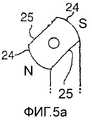
На фиг.5 представлена альтернативная компоновка магнита, предназначенная также для вращения против часовой стрелки, вследствие чего магниты 7а-7d, показанные на фиг.1, заменены вдвое большим количеством магнитов, осевая высота каждого из которых равна половине высоты этих магнитов 7а-7d. Можно использовать и другое количество магнитов. Магниты в середине уложены стопой в последовательности NNSSNN или SSNNSS, вследствие чего все соседние полюсы оказываются на спиральной полосе. По сравнению с магнитом 7 сепаратора согласно фиг.1 комбинации соседних N-N и S-S-полюсов имеют псевдоспиральную форму в соответствии со спиральной компоновкой полосы. Кроме того, полюсы магнита, имеющиеся на магните сепаратора и образованные первым и последним из меньших магнитов в стопе, меньше в направлении укладки стопой, чем магнитные полюсы в средней части магнита сепаратора. Это имеет преимущество, заключающееся в том, что силовая линия магнитного поля от крайнего сверху или крайнего снизу полюса магнита в полосе сильного поля может встретить ближайший к нему полюс магнита противоположной полярности в той же полосе сильного поля. Первый и последний магниты в стопе могут даже иметь меньшую осевую высоту, чем другие магниты в стопе.Figure 5 presents an alternative arrangement of the magnet, also intended for counterclockwise rotation, as a result of which the
В варианте осуществления, показанном на фиг.5, область пониженной магнитной проницаемости имеет форму спиральной выемки 26 во внешней поверхности магнита 7 сепаратора рядом с полосой сильного поля. Благодаря магнитной проницаемости у более магнитного материала, чем у менее магнитного материала (газа, жидкости или твердого вещества), который заполняет выемки, силовые линии внутреннего магнитного поля следуют главным образом по магнитному материалу, а не по материалу, содержащемуся в выемке. Это делает полосу сильного поля с повышенной напряженностью магнитного поля рядом с выемкой 26 более отчетливой. На фиг.5а показано поперечное сечение магнита сепаратора, которое иллюстрирует круговые контуры 24 вокруг диаметрально противоположных полюсов, соединенные, по существу, прямолинейными контурами 25. Прямолинейные контуры соответствуют выемке 26, а круговые контуры - полосам сильного поля с повышенной напряженностью магнитного поля.In the embodiment shown in FIG. 5, the region of reduced magnetic permeability has the form of a
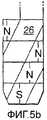
На фиг.5b представлен схематический продольный вид магнита сепаратора, на котором косые линии показывают переход между круговыми контурами и, по существу, прямолинейными контурами. На фиг.5c приведено схематическое представление всей поверхности таким же образом, как на фиг.4. Угол θ спиральной выемки составляет 53°.Fig. 5b is a schematic longitudinal view of a separator magnet, in which oblique lines indicate a transition between circular contours and substantially straight contours. Fig. 5c is a schematic representation of the entire surface in the same manner as in Fig. 4. The angle θ of the spiral recess is 53 °.
В предпочтительном варианте выемка достигает глубины относительно цилиндрической окружной поверхности магнита сепаратора, которая равна расстоянию в зазоре между магнитной поверхностью в полосе сильного поля и опорной поверхностью.In a preferred embodiment, the recess reaches a depth relative to the cylindrical circumferential surface of the separator magnet, which is equal to the distance in the gap between the magnetic surface in the strong field strip and the supporting surface.
Должно быть ясно, что магниты сепаратора, показанные на фиг.4 и 5 для случая вращения против часовой стрелки, также можно подготовить для вращения по часовой стрелке, меняя на ориентацию спиральных полос с правосторонней на левостороннюю.It should be clear that the separator magnets shown in FIGS. 4 and 5 for the case of counterclockwise rotation can also be prepared for clockwise rotation, changing the orientation of the spiral strips from right to left.
Подходящие магниты для устройства для перемещения частиц магнитного материала и для описанной рециркуляционной системы могут быть выполнены из сильно намагничиваемого материала, включая NdFeB, SmCo и AlNiCo-5 или их комбинацию.Suitable magnets for the device for moving particles of magnetic material and for the recirculation system described can be made of highly magnetizable material, including NdFeB, SmCo and AlNiCo-5, or a combination thereof.
В предпочтительном варианте магнит сепаратора также имеет запас магнитной энергии, по меньшей мере, 140 кДж/м3 при комнатной температуре, предпочтительно - более 300 кДж/м3 при комнатной температуре, что характерно для случая магнитов на основе NdFeB. Большой запас энергии обеспечивает уменьшенную длину осевого контакта опорной поверхности с возвратным потоком, а значит, - и резче выраженную конусность опорной поверхности, что выгодно для скорости осевого переноса. Кроме того, требуется меньшая мощность для вращения магнита сепаратора.In a preferred embodiment, the separator magnet also has a magnetic energy supply of at least 140 kJ / m3 at room temperature, preferably more than 300 kJ / m3 at room temperature, which is typical for NdFeB magnets. A large energy supply provides a reduced length of the axial contact of the support surface with the return flow, and therefore, a sharper pronounced taper of the support surface, which is beneficial for the axial transfer speed. In addition, less power is required to rotate the separator magnet.
Гильза 15 и канал 1 для бурового раствора обычно выполнены из немагнитного материала. Они должным образом выполнены путем механической обработки одного куска материала для получения оптимальной механической прочности. Обнаружено, что пригодными являются суперсплавы, включая высокопрочные коррозионно-стойкие немагнитные хромоникелевые сплавы, в том числе продаваемый под названием Inconel 718 или Allvac 718.The
При проходке ствола скважины в пласте породы возвратный поток бурового раствора в кольцевом пространстве ствола скважины (образованном стенкой ствола скважины и проходческим инструментом) может проходить рециркуляционную систему со скоростью 2 м/с или еще большей. Достижение кольцевого пространства ствола скважины магнитным полем должно обуславливать приложение к частицам силы тяги, достаточно большой, чтобы притянуть их к опорной поверхности до того, как они пройдут устройство. В то же время магнитная сила, притягивающая частицы к корпусу, должна быть как можно меньшей для минимизации силы трения, а также требования к мощности для вращения магнита сепаратора. Наиболее подходящим магнитом является тот, который имеет как можно больший коэффициент для наименьшего преобладающего радиального полярного момента и который в типичном случае является магнитом, имеющим преобладающий режим четырехполюсника при определенном запасе энергии.When a wellbore is drilled in a rock formation, the return flow of drilling fluid in the annular space of the wellbore (formed by the wall of the wellbore and the boring tool) can go through a recirculation system at a speed of 2 m / s or even higher. The achievement of the annular space of the borehole with a magnetic field should determine the application of a pulling force to the particles that is large enough to pull them to the supporting surface before they pass the device. At the same time, the magnetic force attracting particles to the body should be as small as possible to minimize the friction force, as well as the power requirements for the rotation of the separator magnet. The most suitable magnet is one that has as large a coefficient as possible for the smallest prevailing radial polar moment and which is typically a magnet having a predominant four-terminal mode with a certain amount of energy.
Для достижения наилучшей эффективности захвата рециркуляционной системы магнит сепаратора предпочтительно размещают в осевом центре ствола скважины. В типичном стволе скважины приемлемо малое осевое смещение величиной до 15% диаметра проходческого инструмента. Вариант осуществления, показанный на фиг.2, имеет осевое смещение магнита, расположенное в осевом направлении изнутри от опорной поверхности 15, составляющее 10% - или приблизительно 7 мм - для целевого ствола скважины диаметром 70 мм.To achieve the best capture efficiency of the recirculation system, the separator magnet is preferably placed in the axial center of the wellbore. In a typical wellbore, a small axial displacement of up to 15% of the diameter of the sinking tool is acceptable. The embodiment shown in FIG. 2 has an axial displacement of the magnet located axially from the inside of the
В качестве альтернативы для цилиндрического магнита сепаратора внешний диаметр магнита сепаратора и внутренний диаметр внутренней стенки 35 можно выполнить меньше с уменьшением осевой высоты. Меньшим магнитам, из которых собирают магнит сепаратора, можно предать форму усеченного конуса для получения сужающегося профиля магнита сепаратора. Можно также уменьшить зазор между магнитом сепаратора и внутренней стенкой опорной гильзы, как и толщину стенки опорной гильзы.Alternatively, for the cylindrical separator magnet, the outer diameter of the separator magnet and the inner diameter of the inner wall 35 can be made smaller with decreasing axial height. The smaller magnets from which the separator magnet is assembled can be shaped into a truncated cone to provide a tapering profile of the separator magnet. You can also reduce the gap between the magnet of the separator and the inner wall of the supporting sleeve, as well as the wall thickness of the supporting sleeve.
Буровой раствор в смесительном сопле 5 или в струе абразивных частиц может содержать абразивные магнитные частицы в концентрации до 10% по объему. Типичная концентрация магнитных абразивных частиц, которая поддерживается каналом 1, находится в диапазоне между 0,1 и 1% по объему. Привод магнита сепаратора в типичном случае осуществляется на частоте вращения, находящейся в диапазоне между 10 и 40 Гц.The drilling fluid in the mixing
Фильтрующее средство, подобное проиллюстрированному выше, в частности содержащее юбку, может быть применено в рециркуляционных системах для магнитных частиц вообще, а в частности - для рециркуляционных систем, имеющих компоновки магнитов сепараторов тех типов, которые отличаются от присутствующей в вышеописанной рециркуляционной системе и примеры которых приведены в документах WO 02/34653 и US 6510907.A filtering device similar to the one illustrated above, in particular containing a skirt, can be used in recirculation systems for magnetic particles in general, and in particular for recirculation systems having separator magnets of types that differ from those present in the recirculation system described above and examples of which are given in documents WO 02/34653 and US 6510907.
Как пояснялось выше, щель 44, образованная между юбкой 43 и опорной поверхностью 15, имеет большое характеристическое отношение размеров, так что часть щели 44 может оставаться открытой, даже если другая часть заблокирована отдельной частицей породы.As explained above, the
В альтернативном варианте можно предусмотреть некоторое количество фильтрационных отверстий, каждое из которых меньше, чем входной проем впускного отверстия 4, по меньшей мере, в одном направлении, причем эти отверстия будут отстоять друг от друга на расстояние, большее, чем размер входного проема впускного отверстия 4.Alternatively, a number of filtering openings can be provided, each of which is smaller than the inlet opening of the inlet 4 in at least one direction, and these holes will be spaced apart from each other by a distance greater than the size of the inlet opening of the inlet 4 .
В любом случае, совокупная проходная площадь одного или нескольких фильтрационных отверстий может быть больше, чем проходная площадь входного проема впускного отверстия 4 для абразивных частиц.In any case, the total passage area of one or more filter openings may be larger than the passage area of the inlet opening of the inlet 4 for abrasive particles.
Claims (10)
Translated fromRussianПриоритет по пунктам:9. The tool according to claim 7, characterized in that the gradient zone is located in a spiral around the separator.
Priority on points:
Applications Claiming Priority (4)
| Application Number | Priority Date | Filing Date | Title |
|---|---|---|---|
| EP03077159.6 | 2003-07-09 | ||
| EP03077159 | 2003-07-09 | ||
| EP04101505 | 2004-04-14 | ||
| EP04101505.8 | 2004-04-14 |
Publications (2)
| Publication Number | Publication Date |
|---|---|
| RU2006103800A RU2006103800A (en) | 2006-06-10 |
| RU2348787C2true RU2348787C2 (en) | 2009-03-10 |
Family
ID=34066505
Family Applications (1)
| Application Number | Title | Priority Date | Filing Date |
|---|---|---|---|
| RU2006103800/03ARU2348787C2 (en) | 2003-07-09 | 2004-07-08 | Instrument for boring object |
Country Status (9)
| Country | Link |
|---|---|
| US (1) | US7448151B2 (en) |
| EP (1) | EP1649130B1 (en) |
| AT (1) | ATE511595T1 (en) |
| AU (1) | AU2004256234B2 (en) |
| CA (1) | CA2531328C (en) |
| EG (1) | EG23938A (en) |
| NO (1) | NO20060617L (en) |
| RU (1) | RU2348787C2 (en) |
| WO (1) | WO2005005765A1 (en) |
Families Citing this family (11)
| Publication number | Priority date | Publication date | Assignee | Title |
|---|---|---|---|---|
| AR045022A1 (en) | 2003-07-09 | 2005-10-12 | Shell Int Research | SYSTEM AND METHOD FOR PERFORATING AN OBJECT |
| CA2531334C (en) | 2003-07-09 | 2012-08-21 | Shell Canada Limited | Magnetic particle separator for an abrasive jetting system |
| AR045021A1 (en) | 2003-07-09 | 2005-10-12 | Shell Int Research | DEVICE FOR THE TRANSPORTATION OF MAGNETIC PARTICLES AND THE TOOL THAT INCLUDES SUCH DEVICE |
| AU2004256234B2 (en) | 2003-07-09 | 2007-12-13 | Shell Internationale Research Maatschappij B.V. | Tool for excavating an object |
| DE602004011388T2 (en) | 2003-10-21 | 2008-05-15 | Shell Internationale Research Maatschappij B.V. | Nozzle assembly and method for excavating a hole in an object |
| ATE374304T1 (en) | 2003-10-29 | 2007-10-15 | Shell Int Research | FLUID JET DRILLING TOOL |
| WO2007057426A2 (en) | 2005-11-18 | 2007-05-24 | Shell Internationale Research Maatschappij B.V. | Device and method for feeding particles into a stream |
| US8479844B2 (en)* | 2007-03-22 | 2013-07-09 | Shell Oil Company | Distance holder with jet deflector |
| EP2142747B1 (en) | 2007-04-03 | 2012-04-18 | Shell Internationale Research Maatschappij B.V. | Method and assembly for abrasive jet drilling |
| US20120255792A1 (en)* | 2009-12-23 | 2012-10-11 | Blange Jan-Jette | Method of drilling and jet drilling system |
| CN108049814B (en)* | 2017-12-08 | 2019-04-30 | 长江大学 | A kind of drilling tool injecting simultaneously circulating particle |
Citations (8)
| Publication number | Priority date | Publication date | Assignee | Title |
|---|---|---|---|---|
| US2727727A (en)* | 1952-01-29 | 1955-12-20 | Exxon Research Engineering Co | Combination pellet impact drilling and rotary shot drilling |
| US2771274A (en)* | 1953-10-28 | 1956-11-20 | Exxon Research Engineering Co | Recycle fluid control in pellet impact drilling |
| US2868509A (en)* | 1956-06-07 | 1959-01-13 | Jersey Prod Res Co | Pellet impact drilling apparatus |
| SU1266990A1 (en)* | 1985-03-22 | 1986-10-30 | Московский Геологоразведочный Институт Им.Серго Орджоникидзе | Hydraulic monitor unit for wells |
| SU1596059A1 (en)* | 1987-12-21 | 1990-09-30 | Всесоюзный проектно-изыскательский и научно-исследовательский институт "Гидропроект" им.С.Я.Жука | Tool shot drilling |
| RU2114274C1 (en)* | 1996-12-05 | 1998-06-27 | Татьяна Николаевна Зубкова | Ball-jet tool for drilling bore-holes |
| RU2125620C1 (en)* | 1993-04-16 | 1999-01-27 | Либби-Оуэнс-Форд Ко. | Method of application of coating to base surface (versions) and device for its embodiment |
| WO2002034653A1 (en)* | 2000-10-26 | 2002-05-02 | Shell Internationale Research Maatschappij B.V. | Device for transporting particles of magnetic material |
Family Cites Families (52)
| Publication number | Priority date | Publication date | Assignee | Title |
|---|---|---|---|---|
| US2779571A (en)* | 1954-04-09 | 1957-01-29 | Exxon Research Engineering Co | Pellet impact drill bit with controlled pellet return |
| US2913113A (en) | 1957-08-30 | 1959-11-17 | Los Angeles By Products Co | Method and apparatus for salvaging metal articles |
| GB892905A (en) | 1960-11-04 | 1962-04-04 | Tot Aanneming Van Werken Voor | Improvements in and relating to apparatus for making vertical holes in the ground |
| US3375886A (en)* | 1963-09-24 | 1968-04-02 | Gulf Research Development Co | Method of treating abrasive-laden drilling liquid |
| US3416614A (en)* | 1965-12-27 | 1968-12-17 | Gulf Research Development Co | Hydraulic jet drilling method using ferrous abrasives |
| US3489280A (en) | 1966-02-03 | 1970-01-13 | Eriez Mfg Co | Magnetic separator having field shaping poles |
| US3508621A (en) | 1968-09-09 | 1970-04-28 | Gulf Research Development Co | Abrasive jet drilling fluid |
| DE2052516A1 (en)* | 1970-10-26 | 1972-04-27 | Sellnow W | |
| US3759367A (en) | 1971-05-13 | 1973-09-18 | E Elliott | Magnetic article sorting apparatus |
| US3831753A (en)* | 1972-12-18 | 1974-08-27 | Gulf Research Development Co | Slotted in-line screen |
| US3938600A (en) | 1973-07-16 | 1976-02-17 | Continental Oil Company | Hydraulic mining nozzle-air lift device |
| JPS50125368A (en) | 1974-03-22 | 1975-10-02 | ||
| US3949354A (en) | 1974-05-15 | 1976-04-06 | Schlumberger Technology Corporation | Apparatus for transmitting well bore data |
| US4055489A (en) | 1975-07-21 | 1977-10-25 | Magnetics International, Inc. | Magnetic separator for solid waste |
| US4119160A (en) | 1977-01-31 | 1978-10-10 | The Curators Of The University Of Missouri | Method and apparatus for water jet drilling of rock |
| DE2832037A1 (en) | 1978-07-21 | 1980-01-31 | Canon Kk | Ferromagnetic material conveyor esp. for photocopying machine - has alternate spiral pole strips on core rotating in non-ferrous fixed tape |
| SU924334A1 (en) | 1980-11-24 | 1982-04-30 | Kb Polt Inst Kujbysheva | Flushing fluid separator for erosion borehole drilling |
| US4396071A (en) | 1981-07-06 | 1983-08-02 | Dresser Industries, Inc. | Mud by-pass regulator apparatus for measurement while drilling system |
| US4555872A (en) | 1982-06-11 | 1985-12-03 | Fluidyne Corporation | High velocity particulate containing fluid jet process |
| EP0119338A1 (en) | 1983-03-17 | 1984-09-26 | Jetin Industrial Limited | High pressure liquid cutting apparatus |
| US4534427A (en) | 1983-07-25 | 1985-08-13 | Wang Fun Den | Abrasive containing fluid jet drilling apparatus and process |
| US4550068A (en) | 1984-01-30 | 1985-10-29 | Markem Corporation | Vertical magnetic brush developing apparatus and method |
| US4637479A (en) | 1985-05-31 | 1987-01-20 | Schlumberger Technology Corporation | Methods and apparatus for controlled directional drilling of boreholes |
| US4787465A (en) | 1986-04-18 | 1988-11-29 | Ben Wade Oakes Dickinson Iii Et Al. | Hydraulic drilling apparatus and method |
| DE4005691A1 (en) | 1990-02-23 | 1991-08-29 | Geesthacht Gkss Forschung | DEVICE FOR CUTTING AND CLEANING OBJECTS BY MEANS OF A WATER-ABRASIVE MIXTURE AT HIGH AMBIENT PRESSURE |
| US4993503A (en) | 1990-03-27 | 1991-02-19 | Electric Power Research Institute | Horizontal boring apparatus and method |
| GB2258416B (en) | 1991-07-27 | 1995-04-19 | Brian David Dale | Nozzle for abrasive cleaning or cutting |
| US5170891A (en) | 1991-09-20 | 1992-12-15 | Venturedyne Limited | Self-cleaning magnetic separator |
| US5291956A (en) | 1992-04-15 | 1994-03-08 | Union Oil Company Of California | Coiled tubing drilling apparatus and method |
| US5314030A (en) | 1992-08-12 | 1994-05-24 | Massachusetts Institute Of Technology | System for continuously guided drilling |
| GB2284837B (en) | 1993-12-17 | 1997-11-12 | Anadrill Int Sa | Directional drilling method and apparatus |
| JPH08168935A (en) | 1994-12-15 | 1996-07-02 | Enshu Ltd | Screw chip conveyor device |
| US5586848A (en) | 1995-05-02 | 1996-12-24 | The Gleason Works | Machine tool chip removal system |
| GB9517378D0 (en) | 1995-08-24 | 1995-10-25 | Sofitech Nv | Hydraulic jetting system |
| EP0763489B1 (en) | 1995-09-13 | 2002-07-17 | Shimonishi Seisakusyo Co., Ltd. | Transport apparatus |
| AUPO062296A0 (en) | 1996-06-25 | 1996-07-18 | Gray, Ian | A system for directional control of drilling |
| GB2324818B (en) | 1997-05-02 | 1999-07-14 | Sofitech Nv | Jetting tool for well cleaning |
| PT994764E (en) | 1997-07-11 | 2003-03-31 | Waterjet Technology Inc | METHOD AND APPARATUS FOR PRODUCING A HIGH SPEED PARTICLE CURRENT |
| US5887667A (en) | 1997-07-16 | 1999-03-30 | Ring-O-Matic Manufacturing Company, Inc. | Method and means for drilling an earthen hole |
| US6176311B1 (en) | 1997-10-27 | 2001-01-23 | Baker Hughes Incorporated | Downhole cutting separator |
| DE29803676U1 (en) | 1998-03-03 | 1998-04-23 | Chiang, Hung-Li, Tzu Kuan Hsiang, Kaohsiung | Metal conveyor |
| DE19852142C2 (en) | 1998-11-12 | 2001-08-16 | Allgaier Werke Gmbh | Device for separating magnetizable parts from pourable or flowable material |
| AR023598A1 (en) | 1999-04-28 | 2002-09-04 | Shell Int Research | A PERFORATION ASSEMBLY TO DRILL A BARRENO IN A LAND FORMATION. |
| US6412643B1 (en) | 2001-02-21 | 2002-07-02 | Robert T. Wysolmierski | Ferrous particle magnetic removal and collection apparatus |
| EG23135A (en) | 2001-03-06 | 2004-04-28 | Shell Int Research | Jet cutting device with deflector |
| CN1367294A (en) | 2002-01-14 | 2002-09-04 | 王彦林 | Earth-squeezing hole-enlarging hole-forming device and its treatment method |
| AU2004256234B2 (en) | 2003-07-09 | 2007-12-13 | Shell Internationale Research Maatschappij B.V. | Tool for excavating an object |
| AR045022A1 (en) | 2003-07-09 | 2005-10-12 | Shell Int Research | SYSTEM AND METHOD FOR PERFORATING AN OBJECT |
| CA2531334C (en) | 2003-07-09 | 2012-08-21 | Shell Canada Limited | Magnetic particle separator for an abrasive jetting system |
| AR045021A1 (en) | 2003-07-09 | 2005-10-12 | Shell Int Research | DEVICE FOR THE TRANSPORTATION OF MAGNETIC PARTICLES AND THE TOOL THAT INCLUDES SUCH DEVICE |
| EP1689966B1 (en) | 2003-10-21 | 2008-01-16 | Shell Internationale Researchmaatschappij B.V. | Nozzle unit and method for excavating a hole in an object |
| DE602004009212T2 (en) | 2003-10-29 | 2008-01-24 | Shell Internationale Research Maatschappij B.V. | FLUIDSTRAHLBOHRWERKZEUG |
- 2004
- 2004-07-08AUAU2004256234Apatent/AU2004256234B2/ennot_activeCeased
- 2004-07-08CACA2531328Apatent/CA2531328C/ennot_activeExpired - Fee Related
- 2004-07-08RURU2006103800/03Apatent/RU2348787C2/ennot_activeIP Right Cessation
- 2004-07-08ATAT04766156Tpatent/ATE511595T1/ennot_activeIP Right Cessation
- 2004-07-08WOPCT/EP2004/051404patent/WO2005005765A1/enactiveSearch and Examination
- 2004-07-08USUS10/563,898patent/US7448151B2/ennot_activeExpired - Fee Related
- 2004-07-08EPEP04766156Apatent/EP1649130B1/ennot_activeExpired - Lifetime
- 2006
- 2006-01-08EGEGNA2006000019patent/EG23938A/enactive
- 2006-02-08NONO20060617Apatent/NO20060617L/ennot_activeApplication Discontinuation
Patent Citations (8)
| Publication number | Priority date | Publication date | Assignee | Title |
|---|---|---|---|---|
| US2727727A (en)* | 1952-01-29 | 1955-12-20 | Exxon Research Engineering Co | Combination pellet impact drilling and rotary shot drilling |
| US2771274A (en)* | 1953-10-28 | 1956-11-20 | Exxon Research Engineering Co | Recycle fluid control in pellet impact drilling |
| US2868509A (en)* | 1956-06-07 | 1959-01-13 | Jersey Prod Res Co | Pellet impact drilling apparatus |
| SU1266990A1 (en)* | 1985-03-22 | 1986-10-30 | Московский Геологоразведочный Институт Им.Серго Орджоникидзе | Hydraulic monitor unit for wells |
| SU1596059A1 (en)* | 1987-12-21 | 1990-09-30 | Всесоюзный проектно-изыскательский и научно-исследовательский институт "Гидропроект" им.С.Я.Жука | Tool shot drilling |
| RU2125620C1 (en)* | 1993-04-16 | 1999-01-27 | Либби-Оуэнс-Форд Ко. | Method of application of coating to base surface (versions) and device for its embodiment |
| RU2114274C1 (en)* | 1996-12-05 | 1998-06-27 | Татьяна Николаевна Зубкова | Ball-jet tool for drilling bore-holes |
| WO2002034653A1 (en)* | 2000-10-26 | 2002-05-02 | Shell Internationale Research Maatschappij B.V. | Device for transporting particles of magnetic material |
Also Published As
| Publication number | Publication date |
|---|---|
| US20060162964A1 (en) | 2006-07-27 |
| RU2006103800A (en) | 2006-06-10 |
| AU2004256234B2 (en) | 2007-12-13 |
| AU2004256234A1 (en) | 2005-01-20 |
| CA2531328C (en) | 2012-08-21 |
| WO2005005765A1 (en) | 2005-01-20 |
| NO20060617L (en) | 2006-04-07 |
| EG23938A (en) | 2008-01-14 |
| CA2531328A1 (en) | 2005-01-20 |
| EP1649130B1 (en) | 2011-06-01 |
| US7448151B2 (en) | 2008-11-11 |
| ATE511595T1 (en) | 2011-06-15 |
| EP1649130A1 (en) | 2006-04-26 |
Similar Documents
| Publication | Publication Date | Title |
|---|---|---|
| AU2002221791B2 (en) | Device for transporting particles of magnetic material | |
| RU2348787C2 (en) | Instrument for boring object | |
| AU2002221791A1 (en) | Device for transporting particles of magnetic material | |
| EP1175546B1 (en) | Abrasive jet drilling assembly | |
| CA2697703C (en) | Debris catcher for collecting well debris | |
| RU2348786C2 (en) | Instrument for boring object | |
| US8999159B2 (en) | Removal of magnetic particles from a fluid | |
| US7493966B2 (en) | System and method for drilling using a modulated jet stream | |
| MX2007014365A (en) | Device and method for retrieving debris from a well. | |
| US7431104B2 (en) | Device for transporting particles of a magnetic material and tool comprising such a device | |
| CN100449108C (en) | tool used to excavate objects |
Legal Events
| Date | Code | Title | Description |
|---|---|---|---|
| MM4A | The patent is invalid due to non-payment of fees | Effective date:20090709 |