RU2347689C1 - Method of reducing vehicle propeller shaft noise - Google Patents
Method of reducing vehicle propeller shaft noiseDownload PDFInfo
- Publication number
- RU2347689C1 RU2347689C1RU2007117240/11ARU2007117240ARU2347689C1RU 2347689 C1RU2347689 C1RU 2347689C1RU 2007117240/11 ARU2007117240/11 ARU 2007117240/11ARU 2007117240 ARU2007117240 ARU 2007117240ARU 2347689 C1RU2347689 C1RU 2347689C1
- Authority
- RU
- Russia
- Prior art keywords
- frequencies
- vibration
- driveshaft
- noise
- vehicle
- Prior art date
Links
- 238000000034methodMethods0.000titleclaimsabstractdescription11
- 230000007246mechanismEffects0.000claimsabstractdescription9
- 230000003595spectral effectEffects0.000claimsabstractdescription4
- 238000013016dampingMethods0.000claimsdescription8
- 230000001133accelerationEffects0.000claimsdescription3
- 230000010355oscillationEffects0.000claimsdescription3
- 238000012360testing methodMethods0.000claimsdescription2
- 230000000694effectsEffects0.000abstractdescription2
- 238000001228spectrumMethods0.000abstractdescription2
- 239000000126substanceSubstances0.000abstract1
- 230000005540biological transmissionEffects0.000description4
- 238000000576coating methodMethods0.000description3
- 239000011248coating agentSubstances0.000description2
- 239000002184metalSubstances0.000description2
- 230000005855radiationEffects0.000description2
- 238000001845vibrational spectrumMethods0.000description2
- 230000003321amplificationEffects0.000description1
- 239000003638chemical reducing agentSubstances0.000description1
- 230000003247decreasing effectEffects0.000description1
- 238000013461designMethods0.000description1
- 239000000428dustSubstances0.000description1
- 239000004519greaseSubstances0.000description1
- 238000009434installationMethods0.000description1
- 239000000314lubricantSubstances0.000description1
- 230000013011matingEffects0.000description1
- 238000011089mechanical engineeringMethods0.000description1
- 238000003199nucleic acid amplification methodMethods0.000description1
- 125000006850spacer groupChemical group0.000description1
- 238000012546transferMethods0.000description1
- 238000012800visualizationMethods0.000description1
Images
Landscapes
- Motor Power Transmission Devices (AREA)
- Shafts, Cranks, Connecting Bars, And Related Bearings (AREA)
Abstract
Description
Translated fromRussianИзобретение относится к области машиностроения, а именно к карданным передачам транспортных средств, и может быть использовано для снижения шума карданных передач.The invention relates to the field of mechanical engineering, namely to cardan transmissions of vehicles, and can be used to reduce the noise of cardan transmissions.
Известен карданный вал, описанный в патенте РФ №2144477 (опубл. 20.01.2000 г.), МПК 7 В60К 17/22, содержащий герметичный кожух и две крестовины, соединенные с соответствующими двумя вилками. Вилки подвижно соединены между собой с помощью шлицевого соединения и снабжены канавками для перетекания масла. Шлицевое соединение выполнено с встроенными клапанами и распорной пружиной для принудительной циркуляции смазки при изменении объема внутренней полости шлицевого соединения.Known driveshaft described in the patent of the Russian Federation No. 2144477 (publ. 20.01.2000), IPC 7 V60K 17/22, containing a sealed casing and two crosses connected to the corresponding two forks. The forks are movably interconnected by means of a spline connection and provided with grooves for the flow of oil. The spline connection is made with built-in valves and a spacer spring for forced circulation of the lubricant when changing the volume of the internal cavity of the spline connection.
Известен также карданный вал наземных транспортных средств, описанный в патенте РФ №2268166 (опубл. 20.01.2006 г.) МПК 7 В60К 17/22, содержащий два шарнира с крестовинами и подшипниками, две фланец-вилки и подвижное шлицевое соединение, выполненное в виде шлицевой втулки и шлицевого вала, с уплотнением в виде телескопической защиты. Фланец-вилки выполнены со сквозным отверстием, крестовины шарниров выполнены с двумя угловыми масленками, расположенными под углом 180° одна относительно другой, а подвижное шлицевое соединение выполнено с предохранительным клапаном, установленным на шлицевой втулке.Also known is the propeller shaft of land vehicles described in RF patent No. 2268166 (publ. 20.01.2006) IPC 7 V60K 17/22, containing two hinges with crosses and bearings, two flange-forks and a movable spline connection made in the form splined sleeve and splined shaft, with a seal in the form of telescopic protection. The flange forks are made with a through hole, the crosses of the hinges are made with two angled grease fittings located at an angle of 180 ° relative to each other, and the movable spline connection is made with a safety valve mounted on the spline sleeve.
Недостатком известных карданных валов является шум, излучаемый валом при передаче им крутящего момента от ведущего к ведомому агрегату. Рассмотрим более подробно причины генерации шума карданным валом на примере грузового автомобиля, в котором карданный вал соединяет выходной фланец коробки переключения передач с входным фланцем редуктора ведущего моста, например заднего. Коробка переключения передач представляет собой механизм, содержащий набор шестеренчатых передач, предназначенный для изменения величины крутящего момента, создаваемого двигателем. В редукторе ведущего моста также расположены шестеренчатые передачи. При вращении шестерен, например коробки переключения передач, происходит взаимное соударение зубьев шестерен при входе в зацепление, в результате чего возникают ярковыраженные тональные вибрации (так называемые зубцовые вибрации) с основной частотой, равной частоте пересопряжения зубьев,A disadvantage of the known driveshafts is the noise emitted by the shaft when it transmits torque from the master to the driven unit. Let us consider in more detail the reasons for the generation of noise by the driveshaft on the example of a truck in which the driveshaft connects the output flange of the gearbox with the input flange of the drive axle gearbox, for example, the rear one. The gearbox is a mechanism containing a set of gears designed to change the amount of torque created by the engine. Gear drives are also located in the drive axle gearbox. When the gears rotate, for example, gearboxes, the gear teeth mutually collide when they enter the gearing, resulting in pronounced tonal vibrations (the so-called gear vibrations) with a fundamental frequency equal to the frequency of the tooth mating,
f0=z·n/60, Гц,f0 = zn / 60, Hz,
где z - число зубьев ведущей шестерни, n - частота вращения, с-1.where z is the number of teeth of the pinion gear, n is the rotation frequency, s-1 .
Кроме основной частоты, как правило, в спектре вибраций шестерен присутствуют гармоники основной частоты, которые рассчитываются по формуле:In addition to the fundamental frequency, as a rule, in the vibration spectrum of the gears there are harmonics of the fundamental frequency, which are calculated by the formula:
fк=к·f0,fk = k f0 ,
где к=1, 2, 3, …, f0 - основная частота.where k = 1, 2, 3, ..., f0 is the fundamental frequency.
Таким образом, шестерни коробки переключения передач генерируют вибрации, которые передаются на выходной фланец коробки переключения передач и далее на карданный вал. Учитывая присутствие гармоник в спектрах вибраций шестерен коробки переключения передач, а также наличие вибраций шестерен редуктора ведущего моста, на карданный вал передаются вибрации в очень широкой частотной полосе в диапазоне рабочих оборотов двигателя (под диапазоном рабочих оборотов здесь понимаются обороты от минимальных оборотов холостого хода до номинальных). Для наглядности в таблице 1 приводятся зубцовые частоты шестерен коробки переключения передач и редуктора ведущего моста автомобиля Урал-4320 с двигателем ЯМЗ 236НЕ2 для 5-й передачи в диапазоне оборотов двигателя 900-2100 мин-1 (приводится также вторая гармоника основной частоты).Thus, the gears of the gearbox generate vibrations that are transmitted to the output flange of the gearbox and then to the driveshaft. Considering the presence of harmonics in the vibration spectra of the gears of the gearbox, as well as the presence of vibrations of the gears of the gearbox of the drive axle, vibrations are transmitted to the driveshaft in a very wide frequency band in the range of engine operating revolutions (here, the range of operating revolutions refers to revolutions from minimum idle to nominal ) For clarity, Table 1 shows the gear frequency of the gears of the gearbox and gearbox of the drive axle of the Ural-4320 automobile with the YaMZ 236NE2 engine for 5th gear in the engine speed range of 900-2100 min-1 (the second harmonic of the main frequency is also given).
Таким образом, на карданный вал рассмотренного выше автомобиля предаются вибрации шестеренчатых механизмов в частотной полосе 103-2424 Гц (учтены только основные частоты и гармоники).Thus, the vibrations of gear mechanisms in the frequency band 103-2424 Hz are transmitted to the driveshaft of the car considered above (only the main frequencies and harmonics are taken into account).
Карданный вал, являясь по своей технической сути полой трубой с шарнирами на ее концах (характерная длина вала для грузовых автомобилей составляет 1,5-2,0 м, диаметр ~0,1 м, толщина стенки трубы ~7·10-3 м), обладает набором собственных частот колебаний и соответствующих им собственных форм колебаний, расположенных в диапазоне 100-10000 Гц и выше. При этом присутствуют как балочные колебания, так и колебания с изменением формы поперечного сечения вала («сплющивание» формы поперечного сечения). При совпадении частот вибраций, источником которых являются шестерни коробки переключения передач и редуктора ведущего моста, с собственными частотами колебаний карданного вала последний начинает излучать интенсивный шум резонансного характера (акустический отклик вала), уровни которого существенно превышают нормативные значения. Это и является основным недостатком известных карданных валов.The driveshaft, being in its technical essence a hollow pipe with hinges at its ends (the characteristic shaft length for trucks is 1.5-2.0 m, diameter ~ 0.1 m, pipe wall thickness ~ 7 · 10-3 m) , has a set of natural frequencies and their corresponding natural modes located in the range of 100-10000 Hz and above. In this case, there are both beam vibrations and vibrations with a change in the shape of the cross section of the shaft (“flattening” of the cross section shape). When the vibration frequencies coincide, the source of which are the gears of the gearbox and the drive axle gearbox, with the natural frequencies of the driveshaft, the latter begins to emit intense noise of a resonant nature (acoustic response of the shaft), the levels of which significantly exceed the standard values. This is the main disadvantage of the known driveshafts.
В качестве прототипа выбран способ снижения шума и вибраций карданных валов, описанный в книге «Снижение шума автомобиля», авторы В.Н.Луканин, В.Н.Гудцов, Н.Ф.Бочаров, М., изд-во «Машиностроение», 1981 г., стр.105, 2-й и 3-й абзацы сверху. Способ заключается в том, что внутрь трубы карданного вала вводят динамический виброгаситель, выполненный (частный случай) в виде металлической шайбы, и закрепляют в трубе с помощью резинового элемента. Дополнительно на стенки трубы наносят вибропоглощающие покрытия с высоким коэффициентом потерь. Недостатком способа-прототипа является то, что динамический виброгаситель, вводимый в трубу без предварительного тщательного определения виброакустических характеристик трубы карданного вала и шестеренчатых механизмов, может оказаться малоэффективным (снижение шума на одних собственных частотах колебаний вала и возможное его усиление на других частотах) либо вообще бесполезным в случае отсутствия совпадения зубцовых частот и/или их гармоник механизмов двигателя с собственными частотами колебаний карданного вала. Недостатком вибропоглощающего покрытия, наносимого на поверхность трубы вала, является его недолговечность, поскольку оно подвергается абразивному воздействию пыли, грязи, гравия и т.д. Кроме этого, неравномерный износ покрытия приведет к нарушению динамической балансировки карданного вала.As a prototype, the method of reducing noise and vibration of cardan shafts, described in the book "Decreasing car noise," the authors V.N. Lukanin, V.N. Gudtsov, N.F. Bocharov, M., publishing house "Engineering", was chosen 1981, p. 105, 2nd and 3rd paragraphs above. The method consists in the fact that a dynamic vibration damper, made (a special case) in the form of a metal washer, is introduced into the pipe of the driveshaft and fixed in the pipe using a rubber element. Additionally, vibration-absorbing coatings with a high loss coefficient are applied to the pipe walls. The disadvantage of the prototype method is that a dynamic vibration damper introduced into the tube without first carefully determining the vibrational characteristics of the propeller shaft pipe and gear mechanisms may be ineffective (reducing noise at one eigenfrequency of the shaft vibrations and its possible amplification at other frequencies) or generally useless in the absence of coincidence of the tooth frequencies and / or their harmonics of the engine mechanisms with the natural frequencies of the driveshaft. The disadvantage of the vibration-absorbing coating applied to the surface of the shaft pipe is its fragility, since it is subjected to the abrasive effect of dust, dirt, gravel, etc. In addition, uneven wear of the coating will disrupt the dynamic balancing of the driveshaft.
Задачей, решаемой настоящим изобретением, является повышение эффективности снижения шума карданного вала транспортного средства и минимизация затрат на его акустическую доводку.The problem solved by the present invention is to increase the efficiency of reducing the noise of the propeller shaft of the vehicle and minimizing the cost of its acoustic refinement.
Достигается это тем, что в известном способе снижения шума карданного вала транспортного средства, заключающемся в том, что внутри трубы карданного вала устанавливают вибродемпфирующие элементы:This is achieved by the fact that in the known method of reducing the noise of the driveshaft of a vehicle, which consists in the fact that vibration damping elements are installed inside the tube of the driveshaft:
- предварительно определяют зубцовые частоты и гармоники механизмов двигателя, содержащих шестеренчатые передачи, в диапазоне рабочих оборотов двигателя и собственные частоты колебаний трубы карданного вала;- pre-determine the gear frequencies and harmonics of the engine mechanisms containing gears in the range of engine revolutions and natural frequencies of the driveshaft pipe;
- после этого выделяют значения зубцовых частот и/или их гармоник, совпадающих по величине с собственными частотами колебаний трубы карданного вала;- after that, the values of the tooth frequencies and / or their harmonics, which coincide in magnitude with the natural frequencies of the oscillations of the driveshaft pipe, are isolated;
- проводят испытания транспортного средства в процессе его движения по мерному участку в режиме разгона на различных передачах и записывают внешний шум транспортного средства на запоминающее устройство;- carry out tests of the vehicle during its movement along the measured section in the acceleration mode in various gears and record the external noise of the vehicle on the storage device;
- получают спектральные характеристики записанного шума и по ним определяют частоты, соответствующие максимумам звукового давления, и при их совпадении по величине с собственными частотами колебаний трубы карданного вала определяют собственные формы колебаний трубы на данных частотах и зоны пучностей колебательной скорости для этих собственных форм колебаний;- obtain the spectral characteristics of the recorded noise and determine the frequencies corresponding to the maximums of sound pressure, and if they coincide in magnitude with the natural frequencies of the driveshaft, determine the natural modes of vibration of the pipe at these frequencies and the antinodes of the vibrational velocity for these natural modes of vibration;
- после этого в зонах пучностей колебательной скорости устанавливают вибродемпфирующие элементы.- after that, vibration damping elements are installed in the zones of antinodes of vibrational velocity.
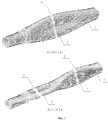
Реализация заявляемого способа осуществляется следующим образом (визуализация форм колебаний приводится фиг.1, на которой изображены: а) - форма колебаний карданного вала с одной зоной пучности колебательной скорости; б) - форма колебаний карданного вала с двумя зонами пучности колебательной скорости; цифрами на фиг.1 обозначены: 1 - труба карданного вала, 2 - зоны пучностей колебательной скорости, 3 - предпочтительное сечение для установки вибропоглощающего элемента внутри трубы (выделено светлым тоном), значения 1344 Гц и 1428 Гц соответствуют некоторым собственным частотам колебаний трубы карданного вала).The implementation of the proposed method is as follows (visualization of the waveforms is shown in figure 1, which shows: a) - the shape of the driveshaft with one antinode vibrational velocity; b) - the mode of vibration of the driveshaft with two zones of antinode of vibrational velocity; the numbers in figure 1 indicate: 1 - the shaft of the driveshaft, 2 - zones of antinodes of vibrational velocity, 3 - the preferred cross-section for installing the vibration-absorbing element inside the tube (highlighted in light tone), the values of 1344 Hz and 1428 Hz correspond to some natural frequencies of vibration of the shaft of the driveshaft )
Для определенной модели транспортного средства, например автомобиля, характеризуемого типом двигателя, трансмиссией, колесной формулой, грузоподъемностью и т.д., определяют зубцовые частоты и их гармоники для механизмов, содержащих шестеренчатые передачи (к ним могут относиться коробка переключения передач, раздаточная коробка, коробка отбора мощности, редуктор ведущего моста и др.), в диапазоне рабочих оборотов двигателя, например в диапазоне 900-2100 мин-1 для дизельного двигателя. Кроме этого определяют собственные частоты колебаний трубы карданного вала данного автомобиля. После этого выделяют значения зубцовых частот и/или их гармоник, совпадающих по величине с собственными частотами колебаний трубы карданного вала. Пусть, например, это будут зубцовые частоты второй гармоники первой пары шестерен коробки переключения передач 1344 Гц и 1428 Гц, которые соответствуют оборотам двигателя 1440 мин-1 и 1530 мин-1 соответственно. Следует отметить, что зубцовые частоты второй пары шестерен коробки переключения передач на оборотах двигателя 1165 мин-1 и 1238 мин-1 также совпадают с собственными частотами колебаний трубы карданного вала (см. таблицу 1). Таким образом, выявлено, что вибрации на зубцовых частотах вторых гармоник шестерен коробки переключения передач могут возбуждать колебания трубы карданного вала на собственных частотах 1344 Гц и 1428 Гц, что может привести к интенсивному акустическому излучению вала на этих частотах. После этого проводят испытания транспортного средства в процессе его движения по мерному участку в режиме разгона на различных передачах (в том числе и на передачах, на которых зубцовые частоты шестерен совпадают с собственными частотами колебаний карданного вала) и записывают внешний шум транспортного средства на запоминающее устройство, например персональный компьютер, адаптированный для записи шума и анализа его характеристик. Затем проводят анализ записанного шума с получением его спектральных характеристик (например, спектров Фурье) и по ним определяют частоты, соответствующие максимумам звукового давления. Если эти частоты (конкретно для выбранного примера 1344 Гц и 1428 Гц) совпадают по величине с собственными частотами колебаний трубы карданного вала (см. фиг.1), то определяют собственные формы колебаний трубы карданного вала на данных частотах и зоны пучностей колебательной скорости (обозначены ссылкой 2 на фиг.1) для этих собственных форм колебаний. После этого в зонах пучностей колебательной скорости (зоны 3 на фиг.1) устанавливают вибродемпфирующие элементы. Последовательность действий способа завершена.For a specific model of a vehicle, for example, a car characterized by engine type, transmission, wheel formula, load carrying capacity, etc., the gear frequencies and their harmonics for mechanisms containing gears are determined (these may include a gearbox, transfer case, gearbox power take-off, drive axle gearbox, etc.), in the range of engine operating revolutions, for example in the range of 900-2100 min-1 for a diesel engine. In addition, the natural frequencies of the propeller shaft pipe of a given vehicle are determined. After that, the values of the tooth frequencies and / or their harmonics, which coincide in magnitude with the natural frequencies of the driveshaft pipe vibrations, are isolated. Let, for example, be the second frequency harmonic frequencies of the first pair of gears of the
Предложенный заявителем способ позволяет по сравнению с прототипом однозначно идентифицировать частоты акустического излучения карданного вала транспортного средства, вызываемого зубцовыми частотами шестеренчатых механизмов, и максимально эффективно снизить шум, излучаемый карданом за счет установки вибродемпфирующих элементов в зонах пучностей колебательной скорости. В качестве вибродемпфирующего элемента может быть предложено жесткое металлическое кольцо, покрытое с внешней стороны тонким слоем резины. Кольцо (либо несколько колец) вставляют внутрь трубы карданного вала с «натягом», т.е. внешний радиус поверхности кольца на 0,05-0,1 мм меньше внутреннего радиуса трубы карданного вала. Предложенный способ апробирован в ОАО «Автомобильный завод «Урал» на одном из опытных образцов автомобилей. В результате проведена виброакустическая диагностика элементов трансмиссии автомобиля, выявлены опасные с точки зрения внешнего шума частоты карданного вала и предложена простая и эффективная конструкция вибродемпфирующего элемента. Учитывая новизну и существенные отличия заявляемого технического решения, заявитель считает, что оно может быть защищено патентом на изобретение.The method proposed by the applicant allows, in comparison with the prototype, to uniquely identify the frequency of the acoustic radiation of the cardan shaft of the vehicle caused by the gear frequencies of the gear mechanisms, and to reduce the noise emitted by the cardan as efficiently as possible due to the installation of vibration damping elements in the antinodes of vibrational velocity. As a vibration damping element, a rigid metal ring coated on the outside with a thin layer of rubber can be proposed. A ring (or several rings) is inserted into the propeller shaft pipe with an “interference fit”, i.e. the outer radius of the ring surface is 0.05-0.1 mm less than the inner radius of the propeller shaft pipe. The proposed method was tested in JSC “Automobile Plant“ Ural ”on one of the prototypes of cars. As a result, vibroacoustic diagnostics of the vehicle’s transmission elements was carried out, cardan shaft frequencies dangerous from the point of view of external noise were identified, and a simple and effective design of the vibration damping element was proposed. Given the novelty and significant differences of the claimed technical solution, the applicant believes that it can be protected by a patent for an invention.
Claims (1)
Translated fromRussianPriority Applications (1)
| Application Number | Priority Date | Filing Date | Title |
|---|---|---|---|
| RU2007117240/11ARU2347689C1 (en) | 2007-05-08 | 2007-05-08 | Method of reducing vehicle propeller shaft noise |
Applications Claiming Priority (1)
| Application Number | Priority Date | Filing Date | Title |
|---|---|---|---|
| RU2007117240/11ARU2347689C1 (en) | 2007-05-08 | 2007-05-08 | Method of reducing vehicle propeller shaft noise |
Publications (1)
| Publication Number | Publication Date |
|---|---|
| RU2347689C1true RU2347689C1 (en) | 2009-02-27 |
Family
ID=40529783
Family Applications (1)
| Application Number | Title | Priority Date | Filing Date |
|---|---|---|---|
| RU2007117240/11ARU2347689C1 (en) | 2007-05-08 | 2007-05-08 | Method of reducing vehicle propeller shaft noise |
Country Status (1)
| Country | Link |
|---|---|
| RU (1) | RU2347689C1 (en) |
Cited By (2)
| Publication number | Priority date | Publication date | Assignee | Title |
|---|---|---|---|---|
| RU2675557C1 (en)* | 2017-11-13 | 2018-12-19 | Акционерное общество "Чебоксарское производственное объединение имени В.И. Чапаева" | Rubber mixture for manufacture of noise absorbing coatings |
| RU2690807C1 (en)* | 2018-06-19 | 2019-06-05 | Акционерное общество "Чебоксарское производственное объединение имени В.И. Чапаева" | Composite rubber mixture for acoustic coatings |
Citations (5)
| Publication number | Priority date | Publication date | Assignee | Title |
|---|---|---|---|---|
| SU1642512A1 (en)* | 1988-01-18 | 1991-04-15 | Государственный Проектный И Научно-Исследовательский Институт По Комплексному Проектированию Предприятий Полиграфической Промышленности | Active noise suppressor |
| RU2009334C1 (en)* | 1988-02-19 | 1994-03-15 | Нойз Кэнселлейшн Текнолоджиз, Инк | System for active silencing of exhaust gases of internal combustion engine |
| US5359662A (en)* | 1992-04-29 | 1994-10-25 | General Motors Corporation | Active noise control system |
| RU2275520C2 (en)* | 2003-02-03 | 2006-04-27 | Тольяттинский государственный университет | Method of and device for complex suppression of vehicle noise |
| RU68966U1 (en)* | 2007-05-21 | 2007-12-10 | Открытое акционерное общество "Автомобильный завод "Урал" | DEVICE FOR REDUCING VEHICLE SHAFT NOISE |
- 2007
- 2007-05-08RURU2007117240/11Apatent/RU2347689C1/ennot_activeIP Right Cessation
Patent Citations (5)
| Publication number | Priority date | Publication date | Assignee | Title |
|---|---|---|---|---|
| SU1642512A1 (en)* | 1988-01-18 | 1991-04-15 | Государственный Проектный И Научно-Исследовательский Институт По Комплексному Проектированию Предприятий Полиграфической Промышленности | Active noise suppressor |
| RU2009334C1 (en)* | 1988-02-19 | 1994-03-15 | Нойз Кэнселлейшн Текнолоджиз, Инк | System for active silencing of exhaust gases of internal combustion engine |
| US5359662A (en)* | 1992-04-29 | 1994-10-25 | General Motors Corporation | Active noise control system |
| RU2275520C2 (en)* | 2003-02-03 | 2006-04-27 | Тольяттинский государственный университет | Method of and device for complex suppression of vehicle noise |
| RU68966U1 (en)* | 2007-05-21 | 2007-12-10 | Открытое акционерное общество "Автомобильный завод "Урал" | DEVICE FOR REDUCING VEHICLE SHAFT NOISE |
Cited By (2)
| Publication number | Priority date | Publication date | Assignee | Title |
|---|---|---|---|---|
| RU2675557C1 (en)* | 2017-11-13 | 2018-12-19 | Акционерное общество "Чебоксарское производственное объединение имени В.И. Чапаева" | Rubber mixture for manufacture of noise absorbing coatings |
| RU2690807C1 (en)* | 2018-06-19 | 2019-06-05 | Акционерное общество "Чебоксарское производственное объединение имени В.И. Чапаева" | Composite rubber mixture for acoustic coatings |
Similar Documents
| Publication | Publication Date | Title |
|---|---|---|
| Tangasawi et al. | Lightly loaded lubricated impacts: idle gear rattle | |
| Wu et al. | Driveline torsional analysis and clutch damper optimization for reducing gear rattle | |
| US9366318B2 (en) | Gearbox, in particular for the drive train of a vehicle | |
| CN204740066U (en) | A mechanical transmission loading noise test bench | |
| RU2347689C1 (en) | Method of reducing vehicle propeller shaft noise | |
| Ognjanović et al. | Gear unit housing effect on the noise generation caused by gear teeth impacts | |
| Deulgaonkar et al. | Review and Diagnostics of noise and vibrations in automobiles | |
| Wei et al. | Modeling and analysis of friction clutches with three stages stiffness and damping for reducing gear rattles of unloaded gears at transmission | |
| RU68966U1 (en) | DEVICE FOR REDUCING VEHICLE SHAFT NOISE | |
| Genç et al. | Modelling and experimental investigation of clutch damper spring stiffness on truck driving comfort | |
| Lee et al. | Identification and reduction of gear whine noise of the axle system in a passenger van | |
| Theodossiades et al. | Root cause identification and physics of impact-induced driveline noise in vehicular powertrain systems | |
| Chen et al. | Application of CAE in design optimization of a wet dual cutch transmission and driveline | |
| Robinette et al. | Characterizing the onset of manual transmission gear rattle part II: analytical results | |
| US20070017768A1 (en) | Torsional damper for a transmission output shaft | |
| Tangasawi et al. | Non-linear vibro-impact phenomenon belying transmission idle rattle | |
| CN111581721B (en) | Gear clearance-considered transient vibration impact numerical modeling method for transmission system | |
| Allam et al. | An experimental investigation of noise emission from a vehicle gearbox system | |
| Wu et al. | The nonlinear characteristics impact of multi-staged stiffness clutch damper on the vehicle creeping | |
| Inavolu et al. | Driveline noise source identification and reduction in commercial vehicles | |
| Krishna et al. | Design and analysis of a two stage reduction gearbox | |
| Baumann | Gear Rattling Noises from Vehicle Transmissions | |
| Crowther et al. | Design and analysis of a gear rattle test rig | |
| CN216407626U (en) | Herringbone gear transmission speed reducer | |
| CN104712705A (en) | Crankshaft flywheel assembly of diesel engine |
Legal Events
| Date | Code | Title | Description |
|---|---|---|---|
| MM4A | The patent is invalid due to non-payment of fees | Effective date:20110509 |