RU2346975C1 - Fluids recovery device - Google Patents
Fluids recovery deviceDownload PDFInfo
- Publication number
- RU2346975C1 RU2346975C1RU2007142333/15ARU2007142333ARU2346975C1RU 2346975 C1RU2346975 C1RU 2346975C1RU 2007142333/15 ARU2007142333/15 ARU 2007142333/15ARU 2007142333 ARU2007142333 ARU 2007142333ARU 2346975 C1RU2346975 C1RU 2346975C1
- Authority
- RU
- Russia
- Prior art keywords
- chamber
- pressure
- regenerated
- jet
- water
- Prior art date
Links
- 239000012530fluidSubstances0.000titleabstractdescription7
- 238000011084recoveryMethods0.000titleabstractdescription3
- XLYOFNOQVPJJNP-UHFFFAOYSA-NwaterSubstancesOXLYOFNOQVPJJNP-UHFFFAOYSA-N0.000claimsabstractdescription23
- 239000007788liquidSubstances0.000claimsdescription17
- 238000002156mixingMethods0.000claimsdescription16
- 230000001172regenerating effectEffects0.000claimsdescription2
- 239000000126substanceSubstances0.000abstractdescription17
- 230000000694effectsEffects0.000abstractdescription3
- 239000000314lubricantSubstances0.000abstract1
- 239000003921oilSubstances0.000description20
- 239000000295fuel oilSubstances0.000description13
- 239000000203mixtureSubstances0.000description13
- 230000008929regenerationEffects0.000description13
- 238000011069regeneration methodMethods0.000description13
- 239000000839emulsionSubstances0.000description12
- 238000000034methodMethods0.000description8
- 238000009434installationMethods0.000description7
- 239000012535impuritySubstances0.000description6
- 239000000047productSubstances0.000description6
- 239000007787solidSubstances0.000description5
- 239000002245particleSubstances0.000description4
- ZWEHNKRNPOVVGH-UHFFFAOYSA-N2-ButanoneChemical compoundCCC(C)=OZWEHNKRNPOVVGH-UHFFFAOYSA-N0.000description3
- NINIDFKCEFEMDL-UHFFFAOYSA-NSulfurChemical compound[S]NINIDFKCEFEMDL-UHFFFAOYSA-N0.000description3
- 238000002485combustion reactionMethods0.000description3
- 239000013049sedimentSubstances0.000description3
- 238000000926separation methodMethods0.000description3
- 239000011593sulfurSubstances0.000description3
- 229910052717sulfurInorganic materials0.000description3
- 238000004581coalescenceMethods0.000description2
- 230000006378damageEffects0.000description2
- 238000010586diagramMethods0.000description2
- 239000000463materialSubstances0.000description2
- 238000005086pumpingMethods0.000description2
- 239000000725suspensionSubstances0.000description2
- IYLGZMTXKJYONK-ACLXAEORSA-N(12s,15r)-15-hydroxy-11,16-dioxo-15,20-dihydrosenecionan-12-yl acetateChemical compoundO1C(=O)[C@](CC)(O)C[C@@H](C)[C@](C)(OC(C)=O)C(=O)OCC2=CCN3[C@H]2[C@H]1CC3IYLGZMTXKJYONK-ACLXAEORSA-N0.000description1
- 230000032683agingEffects0.000description1
- 239000007900aqueous suspensionSubstances0.000description1
- 238000004821distillationMethods0.000description1
- 239000000428dustSubstances0.000description1
- 239000012467final productSubstances0.000description1
- 230000002706hydrostatic effectEffects0.000description1
- 230000003993interactionEffects0.000description1
- 238000013178mathematical modelMethods0.000description1
- 239000002923metal particleSubstances0.000description1
- 239000012188paraffin waxSubstances0.000description1
- 230000000704physical effectEffects0.000description1
- 230000010349pulsationEffects0.000description1
- 238000000746purificationMethods0.000description1
- 102200118166rs16951438Human genes0.000description1
- IYLGZMTXKJYONK-UHFFFAOYSA-NruwenineNatural productsO1C(=O)C(CC)(O)CC(C)C(C)(OC(C)=O)C(=O)OCC2=CCN3C2C1CC3IYLGZMTXKJYONK-UHFFFAOYSA-N0.000description1
- 238000005070samplingMethods0.000description1
- 239000010802sludgeSubstances0.000description1
- 230000003068static effectEffects0.000description1
- 239000010723turbine oilSubstances0.000description1
Images

Landscapes
- Production Of Liquid Hydrocarbon Mixture For Refining Petroleum (AREA)
Abstract
Description
Translated fromRussianИзобретение относится к области регенерации жидкостей, преимущественно загустевших масел.The invention relates to the field of regeneration of liquids, mainly thickened oils.
Наиболее близким техническим решением к заявленному объекту является устройство для регенерации жидкости, известное из DE 10240226 А1, C10G 31/08, 27.03.2003 г., включающее смешивающее устройство для перемешивания регенерируемой жидкости с водой, содержащее приемную камеру, эжектирующее сопло струйного насоса, расположенное осесимметрично камере и включающее в себя центральное и дросселирующее отверстия, приемный коллектор эжектируемого потока регенерируемой жидкости, установленный в приемной камере, перпендикулярно ее оси и связанный с емкостью, содержащей жидкость, подлежащую регенерации (прототип).The closest technical solution to the claimed object is a device for liquid regeneration, known from DE 10240226 A1, C10G 31/08, 03/27/2003, including a mixing device for mixing the regenerated liquid with water, containing a receiving chamber, an ejecting nozzle of the jet pump, located axisymmetrically to the chamber and including a central and throttling hole, a receiving manifold of an ejected flow of regenerated fluid installed in the receiving chamber, perpendicular to its axis and connected to the tank, won fluid to be regenerated (the prototype).
Недостатком известного устройства являются высокое гидравлическое сопротивлением и низкое качество и связанная с этим низкая производительность.A disadvantage of the known device is the high hydraulic resistance and low quality and the associated low productivity.
Технический результат - повышение производительности регенерации жидкостей.The technical result is an increase in the productivity of the regeneration of liquids.
Это достигается тем, что в устройство для регенерации жидкостей, включающее смешивающее устройство для перемешивания регенерируемой жидкости с водой, содержащее приемную камеру, эжектирующее сопло струйного насоса, расположенное осесимметрично камере и включающее в себя центральное и дросселирующее отверстия, приемный коллектор эжектируемого потока регенерируемой жидкости, установленный в приемной камере, перпендикулярно ее оси и связанный с емкостью, содержащей жидкость, подлежащую регенерации, причем приемная камера посредством конфузора соединена с камерой смешения, которая через диффузор связана с прямолинейным транспортировочным трубопроводом, соединенным с отстойником, причем отношение внутреннего диаметра d дросселирующего отверстия сопла эжектора струйного насоса к длине l сопла эжектора составляет d/l=0,25÷0,75, а отношение внутреннего диаметра d дросселирующего отверстия сопла эжектора струйного насоса к диаметру D приемного коллектора составляет d/D=0,05÷0,2.This is achieved by the fact that in the device for the regeneration of liquids, comprising a mixing device for mixing the regenerated liquid with water, containing a receiving chamber, an ejecting nozzle of the jet pump located axisymmetrically to the chamber and including a central and throttling hole, a receiving manifold of the ejected flow of the regenerated liquid, installed in the receiving chamber, perpendicular to its axis and connected with the container containing the liquid to be regenerated, and the receiving chamber by the confuser is connected to the mixing chamber, which through the diffuser is connected to a straight transport pipe connected to the sump, and the ratio of the inner diameter d of the throttle hole of the jet pump nozzle to the length l of the ejector nozzle is d / l = 0.25 ÷ 0.75, and the ratio the inner diameter d of the throttling hole of the nozzle of the jet pump ejector to the diameter D of the intake manifold is d / D = 0.05 ÷ 0.2.
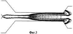
На фиг.1 представлена схема устройства для регенерации жидкостей, на фиг.2 - схема зон водяного факела струи высокого давления, на фиг.3 - изолинии массовой доли конечного продукта.Figure 1 presents a diagram of a device for the recovery of liquids, figure 2 is a diagram of the zones of a water plume of a high pressure jet, figure 3 is an isoline of the mass fraction of the final product.
Устройство для регенерации жидкостей содержит приемную камеру 1, эжектирующее сопло 2 струйного насоса, расположенное осесимметрично камере 1 и включающее в себя центральное 8 и дросселирующее 9 отверстия. В приемной камере 1 перпендикулярно ее оси установлен приемный коллектор 7 диаметром D эжектируемого потока регенерируемой жидкости, связанный с емкостью со смесью, подлежащей регенерации (на чертеже не показана). Приемная камера 1 посредством конфузора 3 соединена с камерой смешения 4, которая через диффузор 5 связана с прямолинейным транспортировочным трубопроводом 6, соединенным с отстойником (на чертеже не показан).The device for the regeneration of liquids contains a receiving chamber 1, an ejecting nozzle 2 of the jet pump, located axisymmetrically to the chamber 1 and including a central 8 and throttling 9 holes. In the receiving chamber 1, perpendicular to its axis, a receiving manifold 7 with a diameter D of an ejected flow of the regenerated liquid is connected, connected with the container with the mixture to be regenerated (not shown in the drawing). The receiving chamber 1 by means of a confuser 3 is connected to the mixing chamber 4, which through a diffuser 5 is connected to a straight transport pipe 6 connected to a sump (not shown).
Для оптимальной работы предлагаемого устройства должны соблюдаться следующие соотношения его параметров:For optimal operation of the proposed device must comply with the following ratios of its parameters:
отношение диаметра d дросселирующего отверстия 9 сопла 2 эжектора струйного насоса к его длине лежит в оптимальном интервале величин: d/l=0,25÷0,75;the ratio of the diameter d of the throttling hole 9 of the nozzle 2 of the jet pump ejector to its length lies in the optimal range of values: d / l = 0.25 ÷ 0.75;
отношение диаметра d дросселирующего отверстия 9 сопла 2 эжектора струйного насоса к диаметру D приемного коллектора 7 диаметром D эжектируемого потока регенерируемой жидкости лежит в оптимальном интервале величин: d/D=0,05÷0,2.the ratio of the diameter d of the throttling hole 9 of the nozzle 2 of the jet pump ejector to the diameter D of the intake manifold 7 with the diameter D of the ejected flow of the regenerated liquid lies in the optimal range of values: d / D = 0.05 ÷ 0.2.
Способ регенерации жидкостей осуществляют следующим образом.The method of regeneration of liquids is as follows.
Высоконапорный подвод воды к соплу 2 эжектора струйного насоса осуществляют по линии, соединяющей установку высокого давления (на чертеже не показана) со входом струйного насоса, расположенного в приемной камере 1. Слив смеси воды и регенерируемых веществ в отстойник осуществляют по трубопроводу (на чертеже не показан). Забор утилизируемой суспензии из емкости осуществляют через приемный коллектор 7, соединяющий слои суспензии со входом эжектора струйного насоса.A high-pressure water supply to the nozzle 2 of the jet pump ejector is carried out along the line connecting the high-pressure unit (not shown in the drawing) to the inlet of the jet pump located in the receiving chamber 1. The mixture of water and regenerated substances is drained into the sump by a pipe (not shown in the drawing ) The collection of the utilized suspension from the tank is carried out through the intake manifold 7, connecting the layers of the suspension with the inlet of the jet pump ejector.
Физические процессы смешения активного и пассивного потоков в струйном аппарате на начальном участке подобны процессам распространения затопленной турбулентной струи в неограниченном объеме. На границах этой струи образуется обширная зона турбулентного взаимодействия активного и пассивного потоков (фиг.3); изменения интенсивности турбулентных пульсаций до 5000 м2/с2. По мере преобразования кинетической энергии струи в энергию давления поле скоростей становится все более равномерным и в диффузоре давление струи преобразуется до противодавления за эжектором, то есть происходит затухание процессов, необходимое для окончательной коалесценции разложившихся составляющих эмульсии (фиг.3).The physical processes of mixing the active and passive flows in the jet apparatus in the initial section are similar to the processes of propagation of a flooded turbulent jet in an unlimited volume. At the boundaries of this jet, an extensive zone of turbulent interaction of active and passive flows is formed (Fig. 3); changes in the intensity of turbulent pulsations up to 5000 m2 / s2 . As the kinetic energy of the jet is converted into pressure energy, the velocity field becomes more uniform and the jet pressure in the diffuser is converted to counter-pressure behind the ejector, that is, the processes are damped, which is necessary for the final coalescence of the decomposed components of the emulsion (Fig. 3).
Кроме того, на основе математической модели получен диапазон, в котором должна находиться длина камеры смешения струйного аппарата, составляющая 9÷12 диаметров камеры смешения (точное значение определяется исходя из состава эмульсии). Именно такая длина камеры смешения обеспечивает разрушение бронирующих оболочек капель воды с целью ее последующей коалесценции в транспортировочном трубопроводе и расслоение компонентов разрушенной эмульсии в отстойной аппаратуре. После появления водяной струи высокого давления из устья сопла поведение струи становится дивергентным. Дивергентность проявляется в двух различных явлениях: трения (возникающего от соприкосновения наружного слоя водяной струи высокого давления с окружающей средой) и радиальных компонентов, образующихся относительно струи (их можно рассматривать как винтообразные колебания). Работа струйной установки определяется действием струи высокого давления, которая создает скоростной и динамический напор, а также гидростатический эффект. Струю высокого давления можно разделить на три части (фиг.2): статическую, которая находится у устья сопла и характеризуется тем, что частицы воды обладают одинаковой скоростью; смешанная часть; динамическая часть, все частицы которой движутся с различной скоростью (создается динамическое воздействие).In addition, on the basis of the mathematical model, a range is obtained in which the length of the mixing chamber of the jet apparatus, comprising 9 ÷ 12 diameters of the mixing chamber (the exact value is determined based on the composition of the emulsion), should be found. It is this length of the mixing chamber that ensures the destruction of the armor shells of water droplets with the aim of its subsequent coalescence in the transport pipeline and the separation of the components of the destroyed emulsion in the settling apparatus. After the appearance of a high-pressure water jet from the mouth of the nozzle, the behavior of the jet becomes divergent. Divergence manifests itself in two different phenomena: friction (arising from the contact of the outer layer of a high pressure water jet with the environment) and radial components formed relative to the jet (they can be considered as helical vibrations). The operation of the jet installation is determined by the action of the high pressure jet, which creates a high-speed and dynamic pressure, as well as a hydrostatic effect. The high pressure jet can be divided into three parts (figure 2): static, which is located at the mouth of the nozzle and is characterized by the fact that water particles have the same speed; mixed part; dynamic part, all particles of which move at different speeds (a dynamic effect is created).
Применение струи высокого давления в устройстве для регенерации исходных продуктов из загрязненных устойчивых эмульсий позволяет осуществлять как перенос и смешение пассивного и активного потоков, так и производить разрушение бронирующих оболочек капель различных веществ. При этом эмульсия подвергается воздействию всех трех частей струи высокого давления в разработанном струйном аппарате.The use of a high-pressure jet in a device for the regeneration of initial products from contaminated stable emulsions allows both the transfer and mixing of passive and active flows and the destruction of the armor shells of drops of various substances. In this case, the emulsion is exposed to all three parts of the high-pressure jet in the developed jet apparatus.
Экспериментальные исследования проводились на тепловой электрической станции с использованием ДУВД (дизельной установки высокого давления) 6/630 с расходом воды при номинальных оборотах - 4 м3/час, содержащей твердые частицы не более 0,2% по массе и 0,2 мм по размерам. Максимальное давление на выходе из насоса - 63 МПа. Установка оснащена дизельным двигателем и трехплунжерным горизонтальным водяным насосом высокого давления. Этот насос позволяет плавно изменять давление на выходе ДУВД. Материалом для регенерации послужила субстанция из открытой бетонной емкости турбинного цеха. Его основой является наиболее загрязненная часть отработанного турбинного масла, остающаяся после слива масла из маслосистемы, загрязненная мелкими частицами металла от трущихся частей подшипников, пылью и грязью, попадающими в масло при его контакте с внешней средой и примесями других нефтепродуктов, используемых при работе оборудования.Experimental studies were carried out at a thermal power plant using a 6/630 internal combustion engine (high-pressure diesel installation) with a water flow rate at a nominal speed of 4 m3 / h, containing solid particles of not more than 0.2% by weight and 0.2 mm in size . The maximum pressure at the pump outlet is 63 MPa. The unit is equipped with a diesel engine and a three-plunger horizontal high-pressure water pump. This pump allows you to smoothly change the pressure at the exit of the internal combustion engine. The material for regeneration was the substance from the open concrete capacity of the turbine workshop. Its basis is the most contaminated part of the spent turbine oil, remaining after draining the oil from the oil system, contaminated with small metal particles from the rubbing parts of the bearings, dust and dirt falling into the oil when it comes in contact with the external environment and impurities of other oil products used in the operation of the equipment.
Испытания проводились при различных значениях следующих параметров:Tests were carried out at various values of the following parameters:
- рабочего давления УВД;- working pressure of air traffic control;
- расстояния от среза сопла до входного сечения камеры смешения;- the distance from the nozzle exit to the inlet section of the mixing chamber;
- длины камеры смешения.- the length of the mixing chamber.
Эффективность действия установки определялась с помощью анализов состава первичной загрязненной смеси и веществ, получаемых на выходе. Взятие проб производилось из отстойника после 60-минутного пребывания смеси веществ в спокойном состоянии. Экспериментальным путем было установлено, что именно такое время необходимо для расслоения веществ, входящих в смесь. При этом пробы брались после прокачки первичной загрязненной смеси веществ через установку при различных режимах ее работы (изменение рабочего давления УВД). Результаты анализов представлены в таблице 1.The effectiveness of the installation was determined using analyzes of the composition of the primary contaminated mixture and substances obtained at the outlet. Sampling was carried out from the sump after a 60-minute stay of the mixture of substances in a calm state. It was established experimentally that it is precisely such a time that is necessary for the separation of substances included in the mixture. In this case, samples were taken after pumping the primary contaminated mixture of substances through the unit under various operating conditions (change in the operating pressure of the air traffic control unit). The results of the analyzes are presented in table 1.
Было установлено улучшение процесса регенерации веществ при увеличении давления воды, подаваемой на сопло струйной установки.It was found to improve the process of regeneration of substances with increasing pressure of water supplied to the nozzle of the jet installation.
После прохождения смеси, содержащей масло, через установку, в отстойнике были получены следующие вещества от верхнего уровня к нижнему: масло, нефтепродукты (мазут и т.п.), эмульсии прямого типа (нефтепродукты в воде), вода, парафинсодержащая водяная суспензия, механический осадок.After passing the mixture containing oil through the unit, the following substances were obtained from the upper to the lower level in the sump: oil, oil products (fuel oil, etc.), direct type emulsions (oil products in water), water, paraffin-containing aqueous suspension, mechanical sediment.
Анализ полученных результатов позволяет сделать вывод об эффективности устройства, выражающейся в разделении содержащихся в исходной смеси веществ и регенерации масла до состояния, пригодного к повторному использованию (отсутствие воды, содержание механических примесей и серы в пределах допустимых норм). В то же время установлено, что повышение рабочего давления УВД с 250 до 500 атм не оказывает существенного влияния на эффективность работы установки.An analysis of the results allows us to conclude that the device is effective in terms of separating the substances contained in the initial mixture and regenerating the oil to a condition suitable for reuse (lack of water, content of mechanical impurities and sulfur within acceptable limits). At the same time, it was found that increasing the operating pressure of the air traffic control system from 250 to 500 atm does not significantly affect the efficiency of the installation.
Как следует из таблицы 1, эмульсия при 250 атм разрушается полностью, а отсутствие влияния увеличения давления УВД более 250 атм на содержание механических примесей обусловлено тем, что крупные и средние частицы удаляются из масла при давлении, меньшем 250 атм, а мелкие (менее 10 мкм) являются мелкодисперсными и легкими, что не позволяет им осаждаться во время отстоя.As follows from table 1, the emulsion at 250 atm completely collapses, and the absence of the effect of an increase in air pressure of more than 250 atm on the content of mechanical impurities is due to the fact that large and medium particles are removed from the oil at a pressure of less than 250 atm, and small (less than 10 microns ) are finely divided and light, which does not allow them to precipitate during sludge.
Кроме анализа химических и физических свойств первичного и получаемого веществ производилось исследование их свойств методом физической дистилляции. Прибор Simdist газохроматический системы TRAGE GC. В результате подтверждено, что в регенерированном масле значительно уменьшилось содержание примесей различных нефтепродуктов, полностью отогнался легкий нефтепродукт «метил-этил-кетон». Для уточнения полученных результатов были произведены исследования полученных веществ на электронном микроскопе (Микрометр ОМ-О ДТ7.216.009ПС). Они сделаны при различном увеличении (в 60, 157 и 500 раз) и показывают высокую степень очистки, произведенную в установке.In addition to analyzing the chemical and physical properties of the primary and resulting substances, their properties were studied by physical distillation. Simdist gas chromatographic device TRAGE GC. As a result, it was confirmed that the content of impurities of various oil products in the regenerated oil was significantly reduced, and the light oil product “methyl ethyl ketone” was completely distilled off. To clarify the results obtained, studies of the obtained substances were carried out using an electron microscope (Micrometer OM-O DT7.216.009PS). They are made at various magnifications (60, 157 and 500 times) and show a high degree of purification produced in the installation.
Отработанная в экспериментальных исследованиях методика регенерации масла и полученные положительные результаты позволили распространить применение установки для регенерации других веществ в промышленных условиях (из более устойчивых эмульсий, чем масляная). Материалом для регенерации послужило вещество, остающееся на дне мазутного бака после откачки из него чистого мазута. Данный осадок представляет из себя твердую, асфальтоподобную субстанцию с содержанием механических примесей различной величины и консистенции, достигающих 20-40% от общего объема осадка, водяных линз, эмульсий обратного типа (вода в мазуте), в том числе устойчивых, образовавшихся из-за возможности их многолетнего «старения». После переработки в установке получены следующие фракции: на дне отстойника - измельченные до пескообразного состояния твердые примеси; замазученная вода (неустойчивая эмульсия прямого типа); мазут с содержанием воды, достаточным и не превышающем норму для его сжигания в тепловых котлах; чистый мазут.The oil regeneration technique worked out in experimental studies and the positive results obtained made it possible to extend the use of the apparatus for the regeneration of other substances under industrial conditions (from more stable emulsions than oil emulsions). The material for regeneration was the substance remaining at the bottom of the fuel oil tank after pumping pure fuel oil out of it. This sediment is a solid, asphalt-like substance with a content of mechanical impurities of various sizes and consistencies, reaching 20-40% of the total sediment volume, water lenses, inverse emulsions (water in fuel oil), including stable ones formed due to the possibility their many years of "aging." After processing in the installation, the following fractions were obtained: at the bottom of the sump - solid impurities crushed to a sandy state; oiled water (unstable emulsion of direct type); fuel oil with a water content sufficient and not exceeding the norm for its combustion in thermal boilers; clean fuel oil.
Результаты анализов разделенных компонентов смеси сведены в таблицу 2. Проведенные экспериментальные исследования показали высокую эффективность предложенного метода разделения загрязненных мазутных эмульсий.The analysis results of the separated components of the mixture are summarized in table 2. Conducted experimental studies have shown the high efficiency of the proposed method for the separation of contaminated fuel oil emulsions.
Claims (1)
Translated fromRussianPriority Applications (1)
| Application Number | Priority Date | Filing Date | Title |
|---|---|---|---|
| RU2007142333/15ARU2346975C1 (en) | 2007-11-16 | 2007-11-16 | Fluids recovery device |
Applications Claiming Priority (1)
| Application Number | Priority Date | Filing Date | Title |
|---|---|---|---|
| RU2007142333/15ARU2346975C1 (en) | 2007-11-16 | 2007-11-16 | Fluids recovery device |
Publications (1)
| Publication Number | Publication Date |
|---|---|
| RU2346975C1true RU2346975C1 (en) | 2009-02-20 |
Family
ID=40531782
Family Applications (1)
| Application Number | Title | Priority Date | Filing Date |
|---|---|---|---|
| RU2007142333/15ARU2346975C1 (en) | 2007-11-16 | 2007-11-16 | Fluids recovery device |
Country Status (1)
| Country | Link |
|---|---|
| RU (1) | RU2346975C1 (en) |
Citations (6)
| Publication number | Priority date | Publication date | Assignee | Title |
|---|---|---|---|---|
| GB572480A (en)* | 1943-12-17 | 1945-10-10 | Liverpool Borax Company Ltd | Improvements in or relating to water treatment |
| US4481130A (en)* | 1981-06-24 | 1984-11-06 | The British Petroleum Company Limited | Method for demulsifying water-in-oil emulsions |
| RU2051954C1 (en)* | 1992-08-03 | 1996-01-10 | Ленинградский сельскохозяйственный институт | Plant for reclaiming of used motor oil |
| RU2054270C1 (en)* | 1992-12-29 | 1996-02-20 | Ассоциация делового сотрудничества "Росинтранс" | Device for processing juices and wine materials in continuous flow |
| RU18359U1 (en)* | 2000-11-13 | 2001-06-20 | Открытое акционерное общество "ВолгоградНИПИморнефть" | DEVICE FOR REGENERATION OF ABSORBENT FROM HARMFUL IMPURITIES |
| DE10240226A1 (en)* | 2001-08-28 | 2003-03-27 | Geesthacht Gkss Forschung | Treatment of pollutant-laden suspension, especially to destroy polycyclic aromatic hydrocarbons, comprises introducing fluid and suspension into pressure chamber and subjecting suspension to cavitation |
- 2007
- 2007-11-16RURU2007142333/15Apatent/RU2346975C1/enactive
Patent Citations (6)
| Publication number | Priority date | Publication date | Assignee | Title |
|---|---|---|---|---|
| GB572480A (en)* | 1943-12-17 | 1945-10-10 | Liverpool Borax Company Ltd | Improvements in or relating to water treatment |
| US4481130A (en)* | 1981-06-24 | 1984-11-06 | The British Petroleum Company Limited | Method for demulsifying water-in-oil emulsions |
| RU2051954C1 (en)* | 1992-08-03 | 1996-01-10 | Ленинградский сельскохозяйственный институт | Plant for reclaiming of used motor oil |
| RU2054270C1 (en)* | 1992-12-29 | 1996-02-20 | Ассоциация делового сотрудничества "Росинтранс" | Device for processing juices and wine materials in continuous flow |
| RU18359U1 (en)* | 2000-11-13 | 2001-06-20 | Открытое акционерное общество "ВолгоградНИПИморнефть" | DEVICE FOR REGENERATION OF ABSORBENT FROM HARMFUL IMPURITIES |
| DE10240226A1 (en)* | 2001-08-28 | 2003-03-27 | Geesthacht Gkss Forschung | Treatment of pollutant-laden suspension, especially to destroy polycyclic aromatic hydrocarbons, comprises introducing fluid and suspension into pressure chamber and subjecting suspension to cavitation |
Similar Documents
| Publication | Publication Date | Title |
|---|---|---|
| US20170088441A1 (en) | Method and device for deep oil removal from wastewater containing low concentration dirty oil | |
| US6875351B2 (en) | Methods and apparatus for oil demulsification and separation of oil and suspended solids from produced water | |
| CN101486515B (en) | Oily wastewater treatment method and whole set apparatus thereof | |
| US20160030856A1 (en) | Distillation reactor module | |
| RU2682543C1 (en) | Separating system for gas cleaning | |
| US4790941A (en) | Fluid decontamination system | |
| US3986954A (en) | Method and apparatus for clarifying contaminated liquids | |
| US12357926B2 (en) | Nanogas shear processing | |
| WO2014094794A1 (en) | Coalescer vessel for separating water from liquid hydrocarbons | |
| Ma et al. | Oil and water separation using a glass microfiber coalescing bed | |
| CN201272722Y (en) | Oil-contained wastewater treatment outfit | |
| US4844804A (en) | Fluid decontamination system | |
| CN202516350U (en) | Lubricating oil demulsification and dehydration device | |
| CN106477670A (en) | A kind of oil-containing emulsifies sewage breaking device | |
| RU2346975C1 (en) | Fluids recovery device | |
| RU2352611C1 (en) | Method of suspension recovery | |
| RU2335326C1 (en) | Immersion water intake filter with dynamic module | |
| RU74119U1 (en) | LIQUID REGENERATION DEVICE | |
| RU2257352C1 (en) | Device for purification of oily waste waters | |
| CN201240885Y (en) | Treatment apparatus for oil-contaminated water | |
| RU2547750C1 (en) | Method of technical oil purification | |
| RU2815781C1 (en) | Method for technical oil purification | |
| CN106698589B (en) | Cutting fluid recycling system and method | |
| CN205687674U (en) | A kind of novel all-in-one oily water separating equipment | |
| Seif et al. | Cleansing of oilfield wastewater using inertial forces |