RU2343968C2 - Method of granulation in fluidised layer and respective granulation plant - Google Patents
Method of granulation in fluidised layer and respective granulation plantDownload PDFInfo
- Publication number
- RU2343968C2 RU2343968C2RU2006102027/15ARU2006102027ARU2343968C2RU 2343968 C2RU2343968 C2RU 2343968C2RU 2006102027/15 ARU2006102027/15 ARU 2006102027/15ARU 2006102027 ARU2006102027 ARU 2006102027ARU 2343968 C2RU2343968 C2RU 2343968C2
- Authority
- RU
- Russia
- Prior art keywords
- fluidized bed
- granulation
- cooling
- fluidised
- layer
- Prior art date
Links
- 238000000034methodMethods0.000titleclaimsabstractdescription38
- 230000003179granulationEffects0.000titleclaimsabstractdescription37
- 238000005469granulationMethods0.000titleclaimsabstractdescription37
- 239000008187granular materialSubstances0.000claimsabstractdescription51
- 238000001816coolingMethods0.000claimsabstractdescription35
- 239000000126substanceSubstances0.000claimsabstractdescription28
- 238000005192partitionMethods0.000claimsabstractdescription11
- 238000009751slip formingMethods0.000claimsabstract2
- NLXLAEXVIDQMFP-UHFFFAOYSA-NAmmonia chlorideChemical compound[NH4+].[Cl-]NLXLAEXVIDQMFP-UHFFFAOYSA-N0.000abstractdescription4
- XSQUKJJJFZCRTK-UHFFFAOYSA-NUreaChemical compoundNC(N)=OXSQUKJJJFZCRTK-UHFFFAOYSA-N0.000abstractdescription4
- 239000004202carbamideSubstances0.000abstractdescription3
- 238000009826distributionMethods0.000abstractdescription3
- PAWQVTBBRAZDMG-UHFFFAOYSA-N2-(3-bromo-2-fluorophenyl)acetic acidChemical compoundOC(=O)CC1=CC=CC(Br)=C1FPAWQVTBBRAZDMG-UHFFFAOYSA-N0.000abstractdescription2
- 235000019270ammonium chlorideNutrition0.000abstractdescription2
- 230000000694effectsEffects0.000abstractdescription2
- 238000010276constructionMethods0.000abstract2
- 235000013877carbamideNutrition0.000abstract1
- 230000002459sustained effectEffects0.000abstract1
- 230000007704transitionEffects0.000abstract1
- 230000015572biosynthetic processEffects0.000description5
- 238000010438heat treatmentMethods0.000description5
- 239000007788liquidSubstances0.000description5
- 238000005265energy consumptionMethods0.000description4
- 238000012423maintenanceMethods0.000description3
- 239000002245particleSubstances0.000description3
- 239000002904solventSubstances0.000description3
- 230000001070adhesive effectEffects0.000description2
- 238000001704evaporationMethods0.000description2
- 230000008020evaporationEffects0.000description2
- 230000002028prematureEffects0.000description2
- 239000012530fluidSubstances0.000description1
- -1for exampleSubstances0.000description1
- 239000008188pelletSubstances0.000description1
- 239000000843powderSubstances0.000description1
- 238000011084recoveryMethods0.000description1
- 230000001105regulatory effectEffects0.000description1
- 238000009827uniform distributionMethods0.000description1
- XLYOFNOQVPJJNP-UHFFFAOYSA-NwaterSubstancesOXLYOFNOQVPJJNP-UHFFFAOYSA-N0.000description1
Images
Classifications
- B—PERFORMING OPERATIONS; TRANSPORTING
- B01—PHYSICAL OR CHEMICAL PROCESSES OR APPARATUS IN GENERAL
- B01J—CHEMICAL OR PHYSICAL PROCESSES, e.g. CATALYSIS OR COLLOID CHEMISTRY; THEIR RELEVANT APPARATUS
- B01J2/00—Processes or devices for granulating materials, e.g. fertilisers in general; Rendering particulate materials free flowing in general, e.g. making them hydrophobic
- B01J2/16—Processes or devices for granulating materials, e.g. fertilisers in general; Rendering particulate materials free flowing in general, e.g. making them hydrophobic by suspending the powder material in a gas, e.g. in fluidised beds or as a falling curtain
Landscapes
- Chemical & Material Sciences (AREA)
- Organic Chemistry (AREA)
- Chemical Kinetics & Catalysis (AREA)
- Devices And Processes Conducted In The Presence Of Fluids And Solid Particles (AREA)
- Glanulating (AREA)
- Physical Or Chemical Processes And Apparatus (AREA)
- Solid-Sorbent Or Filter-Aiding Compositions (AREA)
- Luminescent Compositions (AREA)
Abstract
Description
Translated fromRussianОбласть техники, к которой относится изобретениеFIELD OF THE INVENTION
Настоящее изобретение относится к способу гранулирования в псевдоожиженном слое различных веществ, например мочевины, нитрата аммония, хлорида аммония и других аналогичных им гранулируемых веществ. Изобретение относится, в частности, к способу гранулирования в псевдоожиженном слое, температуру которого регулируют подачей в него горячего воздуха. Изобретение относится также к гранулятору для осуществления указанного выше способа.The present invention relates to a method for granulating in a fluidized bed of various substances, for example, urea, ammonium nitrate, ammonium chloride and other similar granular substances. The invention relates, in particular, to a method of granulation in a fluidized bed, the temperature of which is regulated by the supply of hot air into it. The invention also relates to a granulator for implementing the above method.
Уровень техникиState of the art
Известно, что при гранулировании в псевдоожиженном слое образование гранул происходит путем непрерывного роста (по объему и массе) затравочных зерен, или частиц определенного вещества, непрерывно подаваемых в псевдоожиженный слой одновременно с потоком соответствующего находящегося в жидком состоянии вещества для выращивания гранул. Вещество для выращивания гранул, которое обычно имеет ту же природу, что и гранулируемое вещество, и находится в жидком состоянии, смачивает затравочные зерна и растущие гранулы, которые в совокупности образуют псевдоожиженный слой, прилипает к ним и затвердевает на них.It is known that during granulation in a fluidized bed, the formation of granules occurs by the continuous growth (in volume and mass) of seed grains, or particles of a certain substance, continuously fed into the fluidized bed simultaneously with the flow of the corresponding substance in the liquid state for growing granules. The granule growing substance, which is usually of the same nature as the granular substance and is in a liquid state, moistens the seed grains and growing granules, which together form a fluidized bed, adheres to them and hardens on them.
Находящееся в жидком состоянии вещество для выращивания гранул, которое подают в псевдоожиженный слой при высокой температуре, затвердевает на затравочных зернах и при сохранении своих адгезионных свойств налипает на постепенно растущие в псевдоожиженном слое гранулы.The liquid-growing substance for growing granules, which is fed into the fluidized bed at high temperature, hardens on the seed grains and, while maintaining its adhesive properties, adheres to gradually growing granules in the fluidized bed.
Температуру псевдоожиженного слоя необходимо постоянно поддерживать в диапазоне сравнительно высоких значений, при которых в псевдоожиженном слое происходит испарение растворителя, содержащегося в подаваемом в гранулятор в жидком состоянии вещества для выращивания гранул, в частности воды, которую используют в качестве растворителя при гранулировании мочевины.The temperature of the fluidized bed must be constantly maintained in the range of relatively high values at which evaporation of the solvent contained in the substance for growing granules, in particular water, which is used as a solvent in the granulation of urea, evaporates in the fluidized bed.
При выборе температуры псевдоожиженного слоя учитывают, что возможное охлаждение вещества для выращивания гранул до его взаимодействия с затравочными зернами и растущими гранулами может привести к его преждевременному отверждению со всеми вытекающими отсюда нежелательными последствиями, проявляющимися в потере им своих адгезионных свойств и образовании требующего последующей рекуперации порошка.When choosing the temperature of the fluidized bed, it is taken into account that the possible cooling of the substance for growing granules before it interacts with seed grains and growing granules can lead to its premature curing with all the undesirable consequences resulting from this, resulting in the loss of its adhesive properties and the formation of a powder requiring subsequent recovery.
Для решения этих проблем, т.е. для контроля и регулирования температуры псевдоожиженного слоя в заданных пределах, было предложено использовать дополнительное количество горячего воздуха, подаваемого под давлением в псевдоожиженный слой на том же уровне, на котором в него в жидком виде подают вещество для выращивания гранул.To solve these problems, i.e. To control and regulate the temperature of the fluidized bed within specified limits, it was proposed to use an additional amount of hot air supplied under pressure to the fluidized bed at the same level at which a substance for growing granules is fed into it in liquid form.
При таком регулировании температуры псевдоожиженного слоя во время запуска гранулятора или при работе с небольшими нагрузками либо в иной ситуации, когда ожижающий воздух, который в большом количестве подают в гранулятор для образования и поддержания псевдоожиженного слоя, имеет сравнительно низкую (комнатную) температуру, его необходимо подогреть до требуемой температуры, для чего обычно используют отдельные внешние теплообменники.With this regulation of the temperature of the fluidized bed during the start of the granulator or when working with light loads or in a different situation, when the fluidizing air, which is supplied in large quantities to the granulator to form and maintain the fluidized bed, has a relatively low (room) temperature, it must be heated to the required temperature, for which they usually use separate external heat exchangers.
Очевидно, что при несомненных своих преимуществах такой способ гранулирования обладает и очень серьезным недостатком. Фактически при очень высоком расходе воздуха, циркулирующего в псевдоожиженном слое, упомянутый выше контроль температуры псевдоожиженного слоя требует очень высокого расхода энергии, необходимой для подогрева ожижающего воздуха и воздуха, дополнительно подаваемого в псевдоожиженный слой. Очевидно, что дополнительный расход энергии сопровождается и соответствующим увеличением стоимости полученных в результате гранул.Obviously, with its undoubted advantages, this granulation method has a very serious drawback. In fact, with a very high flow rate of air circulating in the fluidized bed, the aforementioned control of the temperature of the fluidized bed requires a very high flow of energy required to heat the fluidizing air and the air additionally supplied to the fluidized bed. Obviously, the additional energy consumption is accompanied by a corresponding increase in the cost of the resulting granules.
Использование дополнительного оборудования для подогрева воздуха увеличивает затраты на создание установки для гранулирования и соответственно усложняет ее конструкцию.The use of additional equipment for heating the air increases the cost of creating a plant for granulation and, accordingly, complicates its design.
Краткое изложение сущности изобретенияSummary of the invention
В основу настоящего изобретения была положена задача разработать способ гранулирования в псевдоожиженном слое указанного в начале описания типа, функциональные особенности которого позволяли бы устранить описанные выше недостатки известных способов и, в частности, существенно уменьшить суммарный расход энергии, необходимой для поддержания температуры псевдоожиженного слоя на заданном уровне, обеспечивающем оптимальное завершение процесса гранулирования.The basis of the present invention was the task of developing a method of granulation in a fluidized bed of the type indicated at the beginning of the description, the functional features of which would eliminate the disadvantages of the known methods described above and, in particular, significantly reduce the total energy consumption necessary to maintain the temperature of the fluidized bed at a given level ensuring optimal completion of the granulation process.
Эта задача решается с помощью предлагаемого в изобретении способа гранулирования соответствующего вещества в псевдоожиженном слое при его регулируемой температуре с охлаждением в соответствующем псевдоожиженном слое полученных гранул, отличающегося тем, что по меньшей мере часть ожижающего воздуха, выходящего из охлаждающего псевдоожиженного слоя готовых гранул, подают в гранулирующий псевдоожиженный слой.This problem is solved using the method of granulating the corresponding substance in the fluidized bed at its temperature controlled by cooling in the corresponding fluidized bed of the obtained granules, characterized in that at least a portion of the fluidizing air leaving the cooling fluidized bed of the finished granules is supplied to the granulating fluidized bed.
Весь ожижающий воздух, подаваемый в гранулирующий псевдоожиженный слой, предпочтительно поступает из охлаждающего псевдоожиженного слоя.All fluidizing air supplied to the granulating fluidized bed preferably comes from a cooling fluidized bed.
Предпочтительно далее по существу весь ожижающий воздух, выходящий из охлаждающего псевдоожиженного слоя, использовать в качестве ожижающего воздуха в гранулирующем псевдоожиженном слое.Further, substantially all of the fluidizing air leaving the cooling fluidized bed is preferably used as the fluidizing air in the granulating fluidized bed.
В соответствии с еще более предпочтительным вариантом предлагаемый в изобретении способ гранулирования в псевдоожиженном слое отличается тем, что один и тот же поток ожижающего воздуха используют последовательно для непрерывного формирования и поддержания обоих - охлаждающего и гранулирующего - псевдоожиженных слоев, которые расположены относительно потока воздуха по существу последовательно и сообщаются друг с другом.According to an even more preferred embodiment, the inventive fluidized bed granulation method is characterized in that the same fluidizing air stream is used in series to continuously form and maintain both cooling and granulating fluidized beds, which are arranged substantially sequentially with respect to the air flow and communicate with each other.
Другие особенности и преимущества изобретения более подробно рассмотрены ниже на примере одного из вариантов осуществления предлагаемого в изобретении способа гранулирования в псевдоожиженном слое со ссылкой на прилагаемые к описанию чертежи, которые лишь иллюстрируют изобретение, но не ограничивают его объем.Other features and advantages of the invention are described in more detail below on the example of one of the embodiments of the inventive method of granulation in a fluidized bed with reference to the accompanying drawings, which only illustrate the invention, but do not limit its scope.
Краткое описание чертежейBrief Description of the Drawings
На прилагаемых к описанию чертежах, в частности, показано:In the accompanying drawings, in particular, is shown:
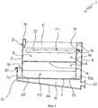
на фиг.1 - схематичный вид в аксонометрии гранулятора для гранулирования различных веществ в псевдоожиженном слое предлагаемым в изобретении способом;figure 1 is a schematic perspective view of a granulator for granulating various substances in a fluidized bed by the method of the invention;
на фиг.2 - схематичный разрез гранулятора, показанного на фиг.1.figure 2 is a schematic section of the granulator shown in figure 1.
Предпочтительный вариант осуществления изобретенияPreferred Embodiment
На прилагаемых к описанию чертежах показан обозначенный общей позицией 1 гранулятор, предназначенный для гранулирования соответствующих веществ в псевдоожиженном слое предлагаемым в изобретении способом.The accompanying description of the drawings shows a granulator, indicated by
Показанный на чертежах гранулятор имеет жесткую самонесущую конструкцию 2, которая выполнена в виде контейнера, имеющего форму параллелепипеда, и которая ограничивает полость А, в которой в двух описанных более подробно ниже псевдоожиженных слоях F1 и F2 происходит процесс гранулирования предлагаемым в изобретении способом.The granulator shown in the drawings has a rigid self-supporting
Несущая конструкция 2 гранулятора (называемая в дальнейшем просто контейнером 2) имеет две длинные боковые стенки 5, 6 и короткие переднюю (или верхнюю) 7 и заднюю 8 стенки и закрыта сверху не показанной на чертежах крышкой, а в основании изготовлена полой из двух листов - верхнего листа 4 и нижнего листа 4а.The supporting
Одной из отличительных особенностей предлагаемого в изобретении гранулятора является наличие в нем расположенного между нижним краем 7а верхней (передней) стенки 7 контейнера 2 и верхним листом 4 состоящего из двух листов основания прохода (или окна) 20, через который внутренняя полость А контейнера 2 сообщается с окружающим пространством. В соответствии с другой отличительной особенностью изобретения листы 4 и 4а основания контейнера 2 примыкают к его задней стенке 8 и проходят под его передней стенкой 7, выступая за ее пределы на заданную величину. К передним свободным краям листов 4, 4а основания приварена передняя, расположенная по существу параллельно передней (верхней) стенке 7 контейнера панель 17, которая образует в нижней передней части контейнера своего рода карман 18, который в показанном на чертежах варианте проходит по всей ширине передней стенки 7 контейнера и через окно 20 сообщается с его внутренней полостью А.One of the distinguishing features of the granulator proposed in the invention is the presence in it of a
Листы 4, 4а основания контейнера 2, его задняя стенка 8 и передняя панель 17 образуют в основании контейнера камеру 19, которая непосредственно сообщается с его внутренней полостью А через верхний лист 4 основания, который для этого выполнен перфорированным, сетчатым, решетчатым или иным образом проницаемым для газа. Расположенная в основании контейнера под его внутренней полостью А камера 19 имеет ограниченную высоту и предназначена, о чем более подробно сказано ниже, для равномерного распределения подаваемого в полость А потока ожижающего воздуха.The
Еще одной отличительной особенностью изобретения является коническая форма распределительной камеры 19, которая постепенно сужается от задней стенки 8 контейнера 2 к передней панели 17. Такая геометрия распределительной камеры обеспечивается определенным наклоном нижнего листа 4а основания к его верхнему листу 4 с постепенным уменьшением расстояния между листами основания в направлении передней панели 17.Another distinctive feature of the invention is the conical shape of the
Внутри контейнера 2 на некотором расстоянии от его задней стенки 8 расположена параллельная ей прямоугольная вертикальная панель 15, которая образует внутри контейнера у его задней стенки камеру 16.Inside the
Вертикальная панель 15 крепится к противоположным длинным стенкам 5 и 6 и верхней стенке 13 контейнера 2, и ее нижний горизонтальный край 15а, расположенный на некотором расстоянии от верхнего листа 4 основания контейнера, образует проход (или окно) 25, через который расположенная в задней части контейнера камера 16 сообщается с его внутренней полостью А.The
Камера 16 сообщается с внутренней полостью А контейнера также через отверстие 11, выполненное в верхней части панели 15.The
Внутри контейнера 2 на определенном расстоянии от верхнего листа 4 основания расположена прямоугольная перегородка 14, которая по периметру герметично крепится к длинным боковым стенкам 5, 6, передней стенке 7 контейнера и к панели 15. Перегородка 14, которая образует во внутренней полости А контейнера зону В гранулирования и служит опорой для псевдоожиженного слоя F1, в котором протекает процесс гранулирования загружаемого в гранулятор вещества, выполнена перфорированной, сетчатой, решетчатой или иным образом проницаемой для ожижающего воздуха, необходимого для формирования и поддержания псевдоожиженного слоя F1.Inside the
На фиг.1 схематично показаны расположенный в верхней части контейнера 2 обычный (известный как таковой) распределитель 10 затравочных зерен или частиц гранулируемого вещества и (также хорошо известные и поэтому не требующие подробного описания) распределители 12 и 13 находящегося в жидком состоянии вещества для выращивания гранул.Fig. 1 schematically shows a conventional (known as such)
На фиг.2 схематично показан расположенный на задней стенке 8 контейнера патрубок 22, через который в камеру 19 подают воздух. Патрубок 22 соединен известными и поэтому не показанными на чертеже устройствами с внешней магистралью, из которой в камеру 19 под избыточным давлением подают необходимый для гранулирования в псевдоожиженном слое воздух.Figure 2 schematically shows the
Ниже со ссылкой на фиг.1 и 2 рассмотрен один из вариантов осуществления предлагаемого в изобретении способа гранулирования.Below, with reference to figures 1 and 2, one of the embodiments of the granulation method according to the invention is considered.
При непрерывной подаче в гранулятор затравочных зерен или частиц гранулируемого вещества и вещества, необходимого для выращивания гранул, в зоне В над перегородкой 14 образуется гранулирующий псевдоожиженный слой F1. Формирование и поддержание гранулирующего псевдоожиженного слоя происходит при непрерывной подаче в камеру 19 ожижающего воздуха, который проходит из нее через перфорированный лист 4 основания в расположенную под перегородкой 14 нижнюю часть внутренней полости А контейнера. В процессе гранулирования (роста гранул) высота псевдоожиженного слоя F1 постепенно увеличивается, и его свободная поверхность поднимается до (предварительно рассчитанного) уровня нижнего края отверстия 11. В тот момент, когда свободная поверхность псевдоожиженного слоя F1 доходит до нижнего края отверстия 11, образующиеся в псевдоожиженном слое очень горячие, готовые гранулы (температура которых зависит от температуры вещества, из которого выращивают гранулы) заданного размера начинают непрерывным потоком, как в плотине, "переливаться" из псевдоожиженного слоя вниз через нижний край отверстия 11.When the seed granules or particles of the granular substance and the substance necessary for growing the granules are continuously fed into the granulator, a granulating fluidized bed F1 is formed in zone B above the
Начиная с этого момента, высота гранулирующего псевдоожиженного слоя F1 остается по существу постоянной.From this moment on, the height of the granulating fluidized bed F1 remains substantially constant.
Готовые гранулы непрерывным потоком проходят через промежуточную (направляющую) камеру 16 и "падают" (каскадом) на состоящий из готовых гранул псевдоожиженный слой F2, который формируется на верхнем перфорированном листе 4 основания контейнера и в котором они охлаждаются тем же потоком ожижающего воздуха, которым формируется и поддерживается псевдоожиженный слой F1. Образующийся в потоке ожижающего воздуха второй псевдоожиженный слой F2 состоит только из готовых гранул, которые заполняют внутреннюю полость А контейнера над верхним перфорированным листом 4 его основания, промежуточную камеру 16 и сообщающийся с ней карман 18.The finished granules in a continuous flow pass through the intermediate (guide)
Давление на свободной поверхности псевдоожиженного слоя F2 в промежуточной камере 16 и в кармане 18 меньше давления на свободной поверхности псевдоожиженного слоя F2 во внутренней полости А контейнера между стенками 7 и 15, и поэтому с учетом того, что все эти зоны функционально похожи на сообщающиеся сосуды, высота псевдоожиженного слоя F2 в промежуточной камере 16 и в кармане 18 оказывается больше высоты псевдоожиженного слоя F2 на верхнем перфорированном листе 4 основания контейнера между стенками 7 и 15.The pressure on the free surface of the fluidized bed F2 in the
Необходимо подчеркнуть, что охлаждающий псевдоожиженный слой F2 сообщается с верхним гранулирующим псевдоожиженным слоем F1 только через перегородку 14, которая служит его опорой.It should be emphasized that the cooling fluidized bed F2 communicates with the upper granulating fluidized bed F1 only through the
Необходимо также отметить, что промежуточная камера 16 выполняет функцию канала, или так называемого стояка, или переточной трубы, по которой горячие гранулы из псевдоожиженного слоя F1 попадают в псевдоожиженный слой F2.It should also be noted that the
В псевдоожиженном слое F2 в процессе теплообмена с потоком ожижающего воздуха, который имеет комнатную температуру, готовые горячие гранулы постепенно охлаждаются. Очевидно, что при охлаждении гранул воздух нагревается. Нагретый в псевдоожиженном слое F2 воздух подают в гранулирующий псевдоожиженный слой F1 и используют в качестве ожижающего для формирования псевдоожиженного слоя образующихся гранул.In the fluidized bed F2, in the process of heat exchange with a stream of fluidizing air, which has room temperature, the finished hot granules are gradually cooled. Obviously, when the granules cool, the air heats up. The air heated in the fluidized bed F2 is supplied to the granulating fluidized bed F1 and used as a fluidizing bed to form the granules formed.
Поэтому расположенную между верхним перфорированным листом 4 основания контейнера и перегородкой 14 часть внутренней полости А контейнера, обычно называемую зоной охлаждения гранул, можно также рассматривать в качестве зоны подогрева ожижающего воздуха, формирующего и поддерживающего гранулирующий псевдоожиженный слой F1.Therefore, located between the upper perforated
Подаваемый в гранулирующий псевдоожиженный слой подогретый ожижающий воздух, с одной стороны, формирует и поддерживает гранулирующий псевдоожиженный слой, а с другой стороны, нагревает его до температуры, при которой существенно или практически полностью исключается вероятность преждевременного отверждения вещества, из которого выращивают гранулы, и происходит необходимое испарение в псевдоожиженный слой растворителя, содержащегося в растворе этого вещества.The heated fluidizing air supplied to the granulating fluidized bed, on the one hand, forms and maintains the granulating fluidized bed, and on the other hand, heats it to a temperature at which the probability of premature curing of the substance from which the granules are grown is substantially or almost completely eliminated and the necessary evaporation into the fluidized bed of the solvent contained in the solution of this substance.
Использование воздуха, отбираемого из охлаждающего псевдоожиженного слоя, в качестве подогретого ожижающего воздуха в гранулирующем псевдоожиженном слое позволяет снизить суммарное потребление воздуха, необходимого для полного окончания процесса гранулирования.The use of air taken from the cooling fluidized bed as a heated fluidizing air in the granulating fluidized bed reduces the total air consumption necessary for the complete completion of the granulation process.
При соответствующей высоте псевдоожиженного слоя F2 (охлаждающего гранулы и подогревающего ожижающий воздух псевдоожиженного слоя) его свободная поверхность в кармане 18 доходит до верхнего края передней панели 17, через который из контейнера 2 выгружают готовые и охлажденные гранулы.At the appropriate height of the fluidized bed F2 (cooling granules and pre-heating the fluidizing air of the fluidized bed), its free surface in the
Поскольку свойства псевдоожиженного слоя похожи, как известно, на свойства жидкости, уровень гранул в кармане 18, в промежуточной камере 16 и во внутренней полости А контейнера во время работы стабилизируется на соответствующей пьезометрической высоте.Since the properties of the fluidized bed are similar, as is known, to the properties of the liquid, the level of granules in the
Необходимо подчеркнуть, что от высоты передней панели 17 зависит не только высота псевдоожиженного слоя F2, но и среднее время нахождения готовых и горячих гранул в зоне охлаждения, а тем самым и температура готовых гранул, выгружаемых из предлагаемого в изобретении контейнера (гранулятора) 2, а также температура подогретого ожижающего воздуха в гранулирующем псевдоожиженном слое.It must be emphasized that not only the height of the fluidized bed F2 depends on the height of the
Начиная с момента "выгрузки" готовых гранул, процесс получения гранул предлагаемым в изобретении способом в предлагаемом в изобретении грануляторе продолжается в установившемся режиме.Starting from the moment of "unloading" of the finished granules, the process for producing granules by the inventive method in the granulator according to the invention continues in steady state.
Главной отличительной особенностью предлагаемого в изобретении способа гранулирования является формирование и поддержание псевдоожиженных слоев F1 и F2 соответственно для гранулирования и охлаждения готовых гранул/подогрева ожижающего воздуха одним и тем же потоком ожижающего воздуха, который проходит через оба псевдоожиженных слоя F1 и F2, по существу последовательно расположенных относительно него.The main distinguishing feature of the granulation method proposed in the invention is the formation and maintenance of fluidized beds F1 and F2, respectively, for granulating and cooling the finished granules / heating the fluidizing air with the same fluidizing air stream that passes through both fluidized beds F1 and F2, essentially sequentially located regarding him.
Второй отличительной особенностью предлагаемого в изобретении способа является по существу каскадное перетекание готовых горячих гранул из гранулирующего псевдоожиженного слоя в охлаждающий псевдоожиженный слой.The second distinctive feature of the method proposed in the invention is essentially a cascade flow of the finished hot granules from the granulating fluidized bed to the cooling fluidized bed.
Основным преимуществом настоящего изобретения является, как уже было отмечено выше, существенное снижение потребляемой энергии по сравнению с известными способами гранулирования в псевдоожиженном слое, в которых для контроля температуры в псевдоожиженном слое дополнительно подают горячий воздух или используют для подогрева ожижающего воздуха на определенном этапе процесса гранулирования соответствующие теплообменники. При высоком расходе ожижающего воздуха и дополнительного горячего воздуха, необходимого для гранулирования в псевдоожиженном слое, такое снижение потребления энергии соответственно обеспечивает и существенное снижение всех эксплуатационных расходов.The main advantage of the present invention is, as already noted above, a significant reduction in energy consumption compared with the known methods of granulation in a fluidized bed, in which to control the temperature in the fluidized bed additionally supply hot air or used to heat the fluidizing air at a certain stage of the granulation process heat exchangers. With a high flow rate of fluidizing air and additional hot air required for granulation in the fluidized bed, such a reduction in energy consumption, respectively, provides a significant reduction in all operating costs.
Такой эффект достигается благодаря использованию одного и того же потока воздуха и для ожижения охлаждающего псевдоожиженного слоя готовых гранул, и гранулирующего псевдоожиженного слоя с эффективным подогревом подаваемого в него ожижающего растущие гранулы воздуха.This effect is achieved through the use of the same air flow and for liquefying the cooling fluidized bed of the finished granules, and the granulating fluidized bed with efficient heating of the fluidizing growing granules of air supplied to it.
В наиболее предпочтительном варианте верхняя часть передней панели 17 выполнена в виде подвижной в вертикальном направлении заслонки 21, положение которой по высоте можно соответствующим образом регулировать.In the most preferred embodiment, the upper part of the
Регулирование высоты заслонки позволяет регулировать высоту охлаждающего псевдоожиженного слоя F2. Так, например, увеличив высоту передней панели 17, можно увеличить и высоту второго псевдоожиженного слоя F2, соответственно увеличив среднее время нахождения в нем горячих готовых гранул.Adjusting the height of the damper allows you to adjust the height of the cooling fluidized bed F2. So, for example, by increasing the height of the
Увеличение времени нахождения горячих готовых гранул во втором псевдоожиженном слое и увеличение продолжительности теплообмена между гранулами и ожижающим воздухом соответственно увеличивает и температуру ожижающего воздуха на входе в первый гранулирующий псевдоожиженный слой F1.The increase in the residence time of the hot finished granules in the second fluidized bed and the increase in the duration of heat exchange between the granules and the fluidizing air respectively increase the temperature of the fluidizing air at the inlet of the first granular fluidized bed F1.
Настоящее изобретение не исключает возможности внесения в рассмотренный выше вариант различных изменений и усовершенствований, не выходя при этом за объем изобретения, определяемый его формулой.The present invention does not exclude the possibility of introducing various changes and improvements into the above variant without departing from the scope of the invention defined by its formula.
Так, например, ширина кармана 18 и промежуточной камеры 16 может быть меньше ширины соответственно короткой передней стенки 7 контейнера и его внутренней панели 15.So, for example, the width of the
Claims (10)
Translated fromRussianApplications Claiming Priority (2)
| Application Number | Priority Date | Filing Date | Title |
|---|---|---|---|
| EP03014631.0 | 2003-06-26 | ||
| EP20030014631EP1491253A1 (en) | 2003-06-26 | 2003-06-26 | Fluid bed granulation process and apparatus |
Publications (2)
| Publication Number | Publication Date |
|---|---|
| RU2006102027A RU2006102027A (en) | 2006-07-27 |
| RU2343968C2true RU2343968C2 (en) | 2009-01-20 |
Family
ID=33395883
Family Applications (1)
| Application Number | Title | Priority Date | Filing Date |
|---|---|---|---|
| RU2006102027/15ARU2343968C2 (en) | 2003-06-26 | 2004-05-19 | Method of granulation in fluidised layer and respective granulation plant |
Country Status (14)
| Country | Link |
|---|---|
| US (1) | US7966745B2 (en) |
| EP (2) | EP1491253A1 (en) |
| CN (1) | CN1812831A (en) |
| AT (1) | ATE343422T1 (en) |
| AU (1) | AU2004253239B2 (en) |
| BR (1) | BRPI0411979B1 (en) |
| CA (1) | CA2528856C (en) |
| DE (1) | DE602004002960T2 (en) |
| MX (1) | MXPA06000199A (en) |
| MY (1) | MY136161A (en) |
| PL (1) | PL1635938T3 (en) |
| RU (1) | RU2343968C2 (en) |
| UA (1) | UA88149C2 (en) |
| WO (1) | WO2005002717A1 (en) |
Families Citing this family (7)
| Publication number | Priority date | Publication date | Assignee | Title |
|---|---|---|---|---|
| EP1491251A1 (en) | 2003-06-26 | 2004-12-29 | Urea Casale S.A. | Fluid bed granulation process and apparatus |
| EA020775B1 (en)* | 2007-08-27 | 2015-01-30 | Бореалис Текнолоджи Ой | Equipment and process for producing polymer pellets |
| ES2706049T3 (en)* | 2007-09-24 | 2019-03-27 | Ziccum Ab | System and method to produce dry formulations |
| EP2161903A1 (en)* | 2008-09-08 | 2010-03-10 | Alcatel, Lucent | System for resolving a service to be provisioned to a terminal device a related terminal device and a related service resolving server |
| CN102274703A (en)* | 2011-05-31 | 2011-12-14 | 山东奥诺能源科技有限公司 | Large-scale continuous energy-saving fluidized bed spraying, granulating and drying process |
| EP3049180B1 (en) | 2013-09-27 | 2020-02-26 | Bexo AS | Fluid bed classification elements |
| US20150275822A1 (en)* | 2014-03-28 | 2015-10-01 | Furness-Newburge, Inc. | Supercharged pulse jet engine and related method of use |
Citations (3)
| Publication number | Priority date | Publication date | Assignee | Title |
|---|---|---|---|---|
| US2635684A (en)* | 1949-05-24 | 1953-04-21 | Ici Ltd | Manufacture of caustic soda granules |
| SU921618A1 (en)* | 1980-01-15 | 1982-04-23 | Специальное Конструкторско-Технологическое Бюро Ленинградского Ордена Октябрьской Революции И Ордена Трудового Красного Знамени Технологического Института Им.Ленсовета | Apparatus for granulating and/or encapsulating loose materials |
| RU2167816C2 (en)* | 1996-10-11 | 2001-05-27 | Норск Хюдро Аса | Method of preparing magnesium chloride granules |
Family Cites Families (159)
| Publication number | Priority date | Publication date | Assignee | Title |
|---|---|---|---|---|
| US2431455A (en)* | 1943-12-24 | 1947-11-25 | Standard Oil Dev Co | Contacting liquids with gaseous fluids in the presence of solid particles |
| US2561394A (en)* | 1946-03-16 | 1951-07-24 | Donald E Marshall | Method of coating particulate materials |
| US2550722A (en)* | 1947-07-10 | 1951-05-01 | Standard Oil Dev Co | Method of recovering solids from gases |
| US2586818A (en)* | 1947-08-21 | 1952-02-26 | Harms Viggo | Progressive classifying or treating solids in a fluidized bed thereof |
| US2648609A (en)* | 1949-01-21 | 1953-08-11 | Wisconsin Alumni Res Found | Method of applying coatings to edible tablets or the like |
| US2629938A (en)* | 1949-03-03 | 1953-03-03 | Kaiser Aluminium Chem Corp | Method and apparatus for treating solids |
| US2701758A (en)* | 1949-07-09 | 1955-02-08 | Metallgesellschaft Ag | Thermal processes |
| US2783187A (en)* | 1954-12-01 | 1957-02-26 | William W Odell | Contacting fluids with solids |
| US2813352A (en)* | 1955-08-17 | 1957-11-19 | Socony Mobil Oil Co Inc | Method for removing liquids from granular solids |
| US3002805A (en)* | 1957-03-07 | 1961-10-03 | Socony Mobil Oil Co Inc | Method for contacting fluids with solid contact materials |
| US3087253A (en)* | 1958-07-11 | 1963-04-30 | Fuller Co | Heat exchange method and apparatus |
| US3036338A (en)* | 1959-01-08 | 1962-05-29 | G & A Lab Inc | Coating and pelletizing of fusible materials |
| US3206865A (en)* | 1960-11-02 | 1965-09-21 | Jr Frank J Mcentee | Method and apparatus for heat exchange in a fluidized bed |
| US3287408A (en)* | 1963-09-17 | 1966-11-22 | Grace W R & Co | Process for rendering urea anti-caking |
| US3295221A (en)* | 1964-06-24 | 1967-01-03 | Phillips Petroleum Co | Process and apparatus for fluidized bed drying |
| FR1473109A (en)* | 1965-01-15 | 1967-03-17 | Hupp Corp | Process and plant for roasting coffee and for similar applications |
| US3328172A (en)* | 1965-01-15 | 1967-06-27 | Hupp Corp | Methods of roasting coffee and similar particulate solids |
| US3395634A (en)* | 1965-01-15 | 1968-08-06 | Hupp Corp | Coffee roasting apparatus |
| US3304619A (en)* | 1965-01-27 | 1967-02-21 | Rudolph E Futer | Method and means for changing the temperature of granular material by gas jets |
| US3372734A (en)* | 1965-06-01 | 1968-03-12 | Pullman Inc | Fluid process useful in the recovery of hydrocarbons from tar sands |
| FR1473956A (en)* | 1965-12-23 | 1967-03-24 | Prat Daniel S A | Process and means for cooling granulated products |
| US3313035A (en)* | 1966-03-14 | 1967-04-11 | Crawford & Russell Inc | Apparatus for drying particulate material |
| FR1484699A (en)* | 1966-03-25 | 1967-06-16 | Potasse & Engrais Chimiques | Improvement in the method of introducing gaseous reagents into a mass of solids |
| US3466021A (en)* | 1967-09-14 | 1969-09-09 | Falconbridge Nickel Mines Ltd | Thermal treatments in fluidized beds |
| US3494046A (en)* | 1967-11-20 | 1970-02-10 | Union Carbide Corp | Fluid bed drying system |
| US3723395A (en)* | 1969-05-21 | 1973-03-27 | Phillips Petroleum Co | Batch-continuous reaction process in a fluidized bed |
| US3615253A (en)* | 1969-05-21 | 1971-10-26 | Phillips Petroleum Co | Batch-continuous reactor |
| US3681851A (en)* | 1970-11-09 | 1972-08-08 | Patrick J Fleming | Novel production and waste treatment process for producing said product |
| AT310675B (en)* | 1970-11-16 | 1973-10-10 | Buss Ag | Device for the continuous treatment of dusty, powdery and granular materials |
| US3818846A (en)* | 1972-04-26 | 1974-06-25 | Combustion Power | Method and apparatus for liquid disposal in a fluid bed reactor |
| US3817696A (en)* | 1972-08-09 | 1974-06-18 | H Hereth | Method of and apparatus for fluidized bed treatment of solids or liquids |
| DE2533010A1 (en)* | 1974-07-26 | 1976-02-05 | Commw Scient Ind Res Org | REACTOR WITH A SPOUT BED OR SPOUT BED FLUIDATE BED |
| FR2313119A1 (en)* | 1975-04-15 | 1976-12-31 | Cerca | NEW TYPE OF FLUIDIZED REACTOR |
| US4320795A (en)* | 1975-07-07 | 1982-03-23 | Shell Oil Company | Process for heat transfer with dilute phase fluidized bed |
| CA1081466A (en)* | 1976-03-26 | 1980-07-15 | David S. Mitchell | Countercurrent plug-like flow of two solids |
| FR2390202A1 (en)* | 1977-05-11 | 1978-12-08 | Anvar | PROCESS AND DEVICE FOR TREATING A PRODUCT IN THE FORM OF BEANS AND APPLICATION TO ROASTING |
| GB1581761A (en)* | 1977-06-09 | 1980-12-17 | Azote Sa Cie Neerlandaise | Urea granulation |
| IL53871A (en)* | 1978-01-23 | 1979-11-30 | Wirguin J | Method and apparatus for drying and processing moisture-containing solids |
| DE2819004C2 (en)* | 1978-04-29 | 1982-05-27 | Dynamit Nobel Ag, 5210 Troisdorf | Process for the production of alkali aluminates from aqueous solutions |
| US4226830A (en)* | 1978-08-28 | 1980-10-07 | Hicap Engineering & Development Corporation | Fluidized bed reactor |
| US4254558A (en)* | 1979-07-31 | 1981-03-10 | Exxon Research & Engineering Co. | Louvered magnetically stabilized fluid cross-flow contactor and processes for using the same |
| US4255403A (en)* | 1979-07-31 | 1981-03-10 | Exxon Research And Engineering Co. | Magnetically stabilized fluid cross-flow contactor having support means and process for using the same |
| US4254616A (en)* | 1979-07-31 | 1981-03-10 | Exxon Research And Engineering Co. | Process for flue gas desulfurization or nitrogen oxide removal using a magnetically stabilized fluid cross-flow contactor |
| US4254557A (en)* | 1979-07-31 | 1981-03-10 | Exxon Research And Engineering Co. | Magnetically stabilized fluid cross-flow contactor and process for using the same |
| US4255166A (en)* | 1979-07-31 | 1981-03-10 | Exxon Research And Engineering Company | Process for the removal of particulates entrained in a fluid using a magnetically stabilized fluid cross-flow contactor |
| JPS5855807B2 (en)* | 1979-10-08 | 1983-12-12 | 三井東圧化学株式会社 | Granulation method |
| DE3066294D1 (en)* | 1979-10-18 | 1984-03-01 | Ici Plc | Process and apparatus for the mixing of fluids and solids |
| JPS5921650B2 (en)* | 1979-11-29 | 1984-05-21 | 東洋エンジニアリング株式会社 | Granulation method |
| JPS601056B2 (en)* | 1980-02-19 | 1985-01-11 | 千代田化工建設株式会社 | Hydrotreatment of heavy hydrocarbon oils containing asphaltenes |
| JPS5732726A (en)* | 1980-08-01 | 1982-02-22 | Mitsui Toatsu Chem Inc | Spouted bed granulation method |
| EP0088174B1 (en)* | 1980-08-06 | 1987-06-16 | William Bradshaw | An improved drying method and apparatus |
| US4395830A (en)* | 1980-09-12 | 1983-08-02 | Jetsonic Processes, Ltd. | Pulse combustion fluidizing dryer |
| WO1983000546A1 (en)* | 1981-08-10 | 1983-02-17 | Walter, Karl, Heinrich | Processing of particulate material |
| DE3139078A1 (en)* | 1981-10-01 | 1983-04-21 | Bergwerksverband Gmbh, 4300 Essen | METHOD FOR REGENERATING HUMID, POWDERED ADSORPTION AGENTS AND DEVICE FOR CARRYING OUT THIS METHOD |
| DE3206236A1 (en)* | 1982-02-20 | 1983-09-01 | Bayer Ag, 5090 Leverkusen | METHOD FOR SIMULTANEOUS VIEWING AND REGULATED, CONTINUOUS DISCHARGE OF GRAINY GOODS FROM FLUIDIZED BED REACTORS |
| US4479308A (en)* | 1982-03-30 | 1984-10-30 | Chevron Research Company | Process and device for recovering heat from a particulate solid |
| GB2129702B (en)* | 1982-09-27 | 1986-05-14 | Adelaide & Wallaroo Fertilizer | Granulation in rotary fluidiser |
| US4424176A (en)* | 1982-09-29 | 1984-01-03 | Tennessee Valley Authority | Process for granulation of molten materials |
| US4506453A (en)* | 1982-09-29 | 1985-03-26 | Tennessee Valley Authority | Enhanced heat transfer process by forced gas recirculation |
| US4561192A (en)* | 1982-11-29 | 1985-12-31 | Dairyman's Cooperative Creamery Assoc. | Spray drying apparatus and method |
| US4627173A (en)* | 1983-04-11 | 1986-12-09 | The Garrett Corporation | Fluid bed hog fuel dryer |
| US4628833A (en)* | 1983-04-11 | 1986-12-16 | The Garrett Corporation | Fluid bed hog fuel dryer |
| US4532155A (en)* | 1983-08-08 | 1985-07-30 | G. D. Searle & Co. | Apparatus and process for coating, granulating and/or drying particles |
| DE3471367D1 (en)* | 1983-12-19 | 1988-06-23 | Duphar Int Res | Method of drying a solid and device therefor |
| US5213820A (en)* | 1984-02-27 | 1993-05-25 | Bayer Aktiengesellschaft | Process and device for fluidized bed spray granulation |
| US4533572A (en)* | 1984-03-20 | 1985-08-06 | Amax Inc. | Process for producing varnish-bonded carbon-coated metal granules |
| BR8403050A (en)* | 1984-06-22 | 1986-01-28 | Petroleo Brasileiro Sa | SELF-HYDROGENATION PROCESS |
| US4670993A (en)* | 1984-08-16 | 1987-06-09 | E.C.C. America Inc. | Method for fluidizing fine kaolin particles |
| US4602438A (en)* | 1985-04-26 | 1986-07-29 | Westinghouse Electric Corp. | Method and apparatus for fluidized steam drying of low rank coals with wet scrubbing |
| US4601113A (en)* | 1985-04-26 | 1986-07-22 | Westinghouse Electric Corp. | Method and apparatus for fluidized steam drying of low-rank coals |
| US4657767A (en)* | 1985-11-07 | 1987-04-14 | Dairyman's Cooperative Creamery Assoc. | Spray drying apparatus and method |
| US5100592A (en)* | 1986-03-12 | 1992-03-31 | Washington University Technology Associated, Inc. | Method and apparatus for granulation and granulated product |
| US5019302A (en)* | 1986-03-12 | 1991-05-28 | Washington University Technology Associates, Inc. | Method for granulation |
| FR2609328B1 (en)* | 1987-01-05 | 1989-05-05 | Armines | PROCESS FOR DRYING PRODUCTS IN DIVIDED FORM, ESPECIALLY CEREALS, AND APPARATUS FOR CARRYING OUT SAID PROCESS |
| US4797271A (en)* | 1987-02-19 | 1989-01-10 | Aluminum Company Of America | Producing alumina granules in a fluidized bed |
| US4704378A (en)* | 1987-02-19 | 1987-11-03 | Aluminum Company Of America | Fluidized bed granulation of rehydratable alumina |
| US5070049A (en)* | 1987-12-16 | 1991-12-03 | Ibiden, Co. Ltd. | Starting composition for the production of silicon carbide and method of producing the same |
| US4839969A (en)* | 1988-02-26 | 1989-06-20 | Permian Research Corporation | Drying method and apparatus |
| US4974336A (en)* | 1988-02-26 | 1990-12-04 | Permian Research Corporation | Drying method |
| US5012033A (en)* | 1988-10-06 | 1991-04-30 | Mobil Oil Corp. | Isoparaffin-olefin alkylation process and catalyst composition thereof |
| ATE96369T1 (en)* | 1988-12-23 | 1993-11-15 | Buehler Ag | METHOD AND DEVICE FOR CONTINUOUSLY CRYSTALIZING POLYESTER MATERIAL. |
| DE3935952A1 (en)* | 1989-09-20 | 1991-03-28 | Tremonis Gmbh Brauerei Nebener | Treating kieselguhr slurry for filter use |
| DE3935953A1 (en)* | 1989-09-20 | 1991-03-28 | Tremonis Gmbh Brauerei Nebener | Treating kieselguhr slurry for filter use |
| NL9101477A (en)* | 1991-09-02 | 1993-04-01 | Dsm Nv | METHOD FOR DRYING AND GRANULATING ASPARTAME. |
| US5332553A (en)* | 1993-04-05 | 1994-07-26 | A. Ahlstrom Corporation | Method for circulating solid material in a fluidized bed reactor |
| DE4316320A1 (en)* | 1993-05-15 | 1994-11-17 | Degussa | Process for the production of sodium perborate monohydrate |
| US5505885A (en)* | 1993-06-29 | 1996-04-09 | Bacardi; Jean M. | Granulation of phosphorus pentasulfide with a predetermined reactivity |
| US5368824A (en)* | 1993-08-18 | 1994-11-29 | Marquess And Nell Inc. | Gas distribution system for fluidized bed reactors |
| US6058623A (en)* | 1993-09-24 | 2000-05-09 | The Chemithon Corporation | Apparatus and process for removing volatile components from a composition |
| ATE156583T1 (en)* | 1993-11-30 | 1997-08-15 | Alcan Int Ltd | METHOD AND DEVICE FOR DRYING SOLID MATERIAL FROM A SUSPENSION |
| US5689024A (en)* | 1994-06-03 | 1997-11-18 | Mobil Oil Corporation | Use of crystalline SUZ-9 |
| US5632102A (en)* | 1994-11-14 | 1997-05-27 | Glatt Gmbh | Process and apparatus for the production and/or treatment of particles |
| GB9500226D0 (en)* | 1995-01-06 | 1995-03-01 | Bp Chem Int Ltd | Nozzle |
| US5849862A (en)* | 1995-06-07 | 1998-12-15 | Cytec Technology Corp. | Processes of spray drying polymer-containing dispersions, water-in-oil emulsions and water-in-oil microemulsions |
| DE69717816T2 (en)* | 1996-05-14 | 2003-10-02 | The Procter & Gamble Co., Cincinnati | METHOD FOR PRODUCING A DETERGENT WITH A LOW BULK BULK WEIGHT BY AGGLOMERATION AND SUBSEQUENT DIELECTRICAL HEATING |
| US6103215A (en)* | 1996-06-07 | 2000-08-15 | Chevron U.S.A. Inc. | Zeolite Me-UTD-1 |
| DE19739864A1 (en)* | 1997-09-11 | 1999-03-18 | Dornier Gmbh Lindauer | Process for treating the exhaust air from thermal drying processes, in particular from processes during the drying of sewage sludge in sewage sludge dryers and plant for carrying out the process |
| BR9812764A (en)* | 1997-10-20 | 2000-08-29 | Procter & Gamble | Dough compositions made with dehydrated potato flakes |
| US6409788B1 (en)* | 1998-01-23 | 2002-06-25 | Crystal Peak Farms | Methods for producing fertilizers and feed supplements from agricultural and industrial wastes |
| US6417133B1 (en)* | 1998-02-25 | 2002-07-09 | Monsanto Technology Llc | Deeply reduced oxidation catalyst and its use for catalyzing liquid phase oxidation reactions |
| US6042369A (en)* | 1998-03-26 | 2000-03-28 | Technomics, Inc. | Fluidized-bed heat-treatment process and apparatus for use in a manufacturing line |
| US6114475A (en)* | 1998-04-06 | 2000-09-05 | Union Carbide Chemicals & Plastics Technology Corporation | Reactor drying by addition of compound that lowers boiling point of water |
| CN100370364C (en)* | 1998-06-25 | 2008-02-20 | 松下电器产业株式会社 | Toner and method for producing the same |
| US6432599B1 (en)* | 1998-06-25 | 2002-08-13 | Matsushita Electric Industrial Co., Ltd. | Toner and method for producing the same |
| US6168709B1 (en)* | 1998-08-20 | 2001-01-02 | Roger G. Etter | Production and use of a premium fuel grade petroleum coke |
| EP0986960A1 (en)* | 1998-09-15 | 2000-03-22 | Dsm N.V. | Mucorales fungi for use in preparation of textured products for foodstuffs |
| ES2269029T3 (en)* | 1999-01-25 | 2007-04-01 | Dsm Ip Assets B.V. | PROCESS FOR THE PREPARATION OF AN ADSORBENT THAT IS CHARGED WITH AN OIL. |
| US6270708B1 (en)* | 1999-03-12 | 2001-08-07 | Tamer International, Ltd. | Agglomerating and drying apparatus |
| US20020179493A1 (en)* | 1999-08-20 | 2002-12-05 | Environmental & Energy Enterprises, Llc | Production and use of a premium fuel grade petroleum coke |
| DE19957664A1 (en)* | 1999-11-30 | 2001-05-31 | Basf Ag | Device for drying granulates, especially polyamide-6, has granulate inlet at top and outlet at bottom, inert gas inlet and outlet in opposite walls and perforated metal partitions across these walls to slow down and distribute gas |
| DE60011299T2 (en)* | 1999-12-21 | 2005-06-16 | Monsanto Technology Llc. | USE OF AN ADDITIONAL PROMOTER IN A LIQUID PHASE OXIDATIVE REACTION CATALYST CONTAINING A CARBOHYDRATED PRECIOUS METAL |
| JP2001187753A (en)* | 1999-12-28 | 2001-07-10 | Toshiba Corp | Oxygenated hydrocarbon synthesis plant |
| JP4663887B2 (en)* | 2000-05-01 | 2011-04-06 | フロイント産業株式会社 | Fluidized bed granulation coating apparatus and fluidized bed granulation coating method |
| US6927304B2 (en)* | 2000-05-22 | 2005-08-09 | Monsanto Technology Llc | De-oxygenation treatment for noble metal on carbon catalysts used in liquid phase oxidation reactions |
| WO2001096260A1 (en)* | 2000-06-14 | 2001-12-20 | Chisso Corporation | Method for producing coated bioactive granule |
| US7632434B2 (en)* | 2000-11-17 | 2009-12-15 | Wayne O. Duescher | Abrasive agglomerate coated raised island articles |
| US6827786B2 (en)* | 2000-12-26 | 2004-12-07 | Stephen M Lord | Machine for production of granular silicon |
| BR0208299B1 (en)* | 2001-03-21 | 2012-08-07 | fluidized bed granulation process. | |
| WO2002078842A1 (en)* | 2001-03-30 | 2002-10-10 | Council Of Scientific And Industrial Research | A novel catalytic formulation and its preparation |
| US6645905B2 (en)* | 2001-04-25 | 2003-11-11 | Rohm And Haas Company | Annealed and promoted catalyst |
| US7396955B2 (en)* | 2001-04-25 | 2008-07-08 | Rohm And Haas Company | Annealed and promoted catalyst |
| US7348292B2 (en)* | 2001-04-25 | 2008-03-25 | Rohm And Haas Company | Annealed and promoted catalyst |
| US6841699B2 (en)* | 2001-04-25 | 2005-01-11 | Rohm And Haas Company | Recalcined catalyst |
| US6746496B1 (en)* | 2002-01-15 | 2004-06-08 | Sandia Corporation | Compact solid source of hydrogen gas |
| US7232635B2 (en)* | 2002-02-04 | 2007-06-19 | Konica Corporation | Image forming method, image forming apparatus, and processing cartridge |
| US7390920B2 (en)* | 2002-02-14 | 2008-06-24 | Monsanto Technology Llc | Oxidation catalyst and process |
| WO2003068387A1 (en)* | 2002-02-14 | 2003-08-21 | Monsanto Technology Llc | Oxidation catalyst and process for its preparation and process for oxidation using it |
| MXPA05000001A (en)* | 2002-06-28 | 2005-04-08 | Monsanto Technology Llc | Use of tellurium in carbon-supported, noble metal-containing catalysts for liquid phase oxidation reactions. |
| BRPI0408215B1 (en)* | 2003-03-10 | 2015-11-03 | Broin And Associates Inc | process for ethanol production using raw starch |
| ATE405170T1 (en)* | 2003-05-06 | 2008-09-15 | Gumlink As | METHOD FOR PRODUCING CHEWING GUM GRANULES AND COMPRESSED CHEWING GUM PRODUCTS, AND A CHEWING GUM GRANULATING SYSTEM |
| US7964529B2 (en)* | 2003-07-11 | 2011-06-21 | The Clorox Company | Method of agglomeration |
| US7488464B2 (en)* | 2003-07-31 | 2009-02-10 | Enviroscrub Technologies Corporation | Metal oxide processing methods and systems |
| WO2005016519A1 (en)* | 2003-08-14 | 2005-02-24 | Monsanto Technology Llc | Transition metal-carbide and nitride containing catalysts , their preparation and use as oxidation and dehydrogenation catalysts |
| US7635414B2 (en)* | 2003-11-03 | 2009-12-22 | Solaicx, Inc. | System for continuous growing of monocrystalline silicon |
| US7820418B2 (en)* | 2004-06-25 | 2010-10-26 | Grainvalue, Llc | Corn fractionation method |
| US7024796B2 (en)* | 2004-07-19 | 2006-04-11 | Earthrenew, Inc. | Process and apparatus for manufacture of fertilizer products from manure and sewage |
| US20060101881A1 (en)* | 2004-07-19 | 2006-05-18 | Christianne Carin | Process and apparatus for manufacture of fertilizer products from manure and sewage |
| US7024800B2 (en)* | 2004-07-19 | 2006-04-11 | Earthrenew, Inc. | Process and system for drying and heat treating materials |
| US7685737B2 (en)* | 2004-07-19 | 2010-03-30 | Earthrenew, Inc. | Process and system for drying and heat treating materials |
| US8703639B2 (en)* | 2004-09-15 | 2014-04-22 | Monsanto Technology Llc | Oxidation catalyst and its use for catalyzing liquid phase oxidation reactions |
| US8062410B2 (en)* | 2004-10-12 | 2011-11-22 | Great River Energy | Apparatus and method of enhancing the quality of high-moisture materials and separating and concentrating organic and/or non-organic material contained therein |
| US7404262B2 (en)* | 2004-10-12 | 2008-07-29 | Pesco, Inc. | Heat-moisture control in agricultural-product production using moisture from water vapor extraction |
| EP2366452A3 (en)* | 2005-02-17 | 2012-08-22 | Monsanto Technology LLC | Transition metal-containing catalysts and their use as oxidation catalysts |
| US20070137062A1 (en)* | 2005-07-05 | 2007-06-21 | Eck Gary A | Increased Negative Static Pressure Drying |
| US7610692B2 (en)* | 2006-01-18 | 2009-11-03 | Earthrenew, Inc. | Systems for prevention of HAP emissions and for efficient drying/dehydration processes |
| EP1840203A1 (en)* | 2006-03-31 | 2007-10-03 | Cargill, Inc. | Enzymatic modification in a continuously regenerated packed bed column |
| US7622033B1 (en)* | 2006-07-12 | 2009-11-24 | Uop Llc | Residual oil coking scheme |
| CA2658228A1 (en)* | 2006-07-28 | 2008-01-31 | Steve D. Shivvers | Counter flow cooling drier with integrated heat recovery |
| KR100783667B1 (en)* | 2006-08-10 | 2007-12-07 | 한국화학연구원 | Method and apparatus for manufacturing particulate polycrystalline silicon |
| US7820126B2 (en)* | 2006-08-18 | 2010-10-26 | Iosil Energy Corporation | Method and apparatus for improving the efficiency of purification and deposition of polycrystalline silicon |
| US20080209755A1 (en)* | 2007-01-26 | 2008-09-04 | Shivvers Steve D | Counter flow cooling drier with integrated heat recovery with fluid recirculation system |
| ATE464522T1 (en)* | 2007-02-09 | 2010-04-15 | Braunschweigische Maschb Ansta | DEVICE FOR REMOVAL OF FLUID AND/OR SOLIDS |
| EP1955599A1 (en)* | 2007-02-09 | 2008-08-13 | Braunschweigische Maschinenbauanstalt AG | Method and device for drying by-products |
| JP2008193971A (en)* | 2007-02-14 | 2008-08-28 | Sadako Morimoto | Bed for pet |
| WO2009061745A2 (en)* | 2007-11-05 | 2009-05-14 | Energy Enzymes, Inc. | Process of producing ethanol using starch with enzymes generated through solid state culture |
| US9457048B2 (en)* | 2008-02-05 | 2016-10-04 | Wellosophy Corporation | Absorbent ingestible agents and associated methods of manufacture and use |
| JP2011516290A (en)* | 2008-04-11 | 2011-05-26 | イオシル エナジー コーポレイション | Method and apparatus for recovery of silicon and silicon carbide from spent wafer sawing slurry |
| WO2010017231A1 (en)* | 2008-08-04 | 2010-02-11 | Hariharan Alleppey V | Method to convert waste silicon to high purity silicon |
| FR2942803B1 (en)* | 2009-03-09 | 2012-03-16 | Isaac Behar | SYSTEMS AND METHODS FOR TRANSFORMING BIOMASS TO LIQUID COMBUSTIBLES |
- 2003
- 2003-06-26EPEP20030014631patent/EP1491253A1/ennot_activeWithdrawn
- 2004
- 2004-05-19BRBRPI0411979-7Apatent/BRPI0411979B1/ennot_activeIP Right Cessation
- 2004-05-19RURU2006102027/15Apatent/RU2343968C2/enactive
- 2004-05-19CNCNA2004800178437Apatent/CN1812831A/enactivePending
- 2004-05-19MXMXPA06000199Apatent/MXPA06000199A/enactiveIP Right Grant
- 2004-05-19AUAU2004253239Apatent/AU2004253239B2/ennot_activeExpired
- 2004-05-19CACA2528856Apatent/CA2528856C/ennot_activeExpired - Lifetime
- 2004-05-19DEDE602004002960Tpatent/DE602004002960T2/ennot_activeExpired - Lifetime
- 2004-05-19USUS10/562,130patent/US7966745B2/ennot_activeExpired - Lifetime
- 2004-05-19EPEP04733771Apatent/EP1635938B1/ennot_activeExpired - Lifetime
- 2004-05-19ATAT04733771Tpatent/ATE343422T1/ennot_activeIP Right Cessation
- 2004-05-19UAUAA200600617Apatent/UA88149C2/enunknown
- 2004-05-19WOPCT/EP2004/005376patent/WO2005002717A1/enactiveIP Right Grant
- 2004-05-19PLPL04733771Tpatent/PL1635938T3/enunknown
- 2004-05-28MYMYPI20042081Apatent/MY136161A/enunknown
Patent Citations (3)
| Publication number | Priority date | Publication date | Assignee | Title |
|---|---|---|---|---|
| US2635684A (en)* | 1949-05-24 | 1953-04-21 | Ici Ltd | Manufacture of caustic soda granules |
| SU921618A1 (en)* | 1980-01-15 | 1982-04-23 | Специальное Конструкторско-Технологическое Бюро Ленинградского Ордена Октябрьской Революции И Ордена Трудового Красного Знамени Технологического Института Им.Ленсовета | Apparatus for granulating and/or encapsulating loose materials |
| RU2167816C2 (en)* | 1996-10-11 | 2001-05-27 | Норск Хюдро Аса | Method of preparing magnesium chloride granules |
Also Published As
| Publication number | Publication date |
|---|---|
| ATE343422T1 (en) | 2006-11-15 |
| CN1812831A (en) | 2006-08-02 |
| MXPA06000199A (en) | 2006-04-07 |
| CA2528856A1 (en) | 2005-01-13 |
| AU2004253239A1 (en) | 2005-01-13 |
| DE602004002960D1 (en) | 2006-12-07 |
| US20070000813A1 (en) | 2007-01-04 |
| EP1635938A1 (en) | 2006-03-22 |
| EP1491253A1 (en) | 2004-12-29 |
| MY136161A (en) | 2008-08-29 |
| UA88149C2 (en) | 2009-09-25 |
| PL1635938T3 (en) | 2007-01-31 |
| AU2004253239B2 (en) | 2010-01-07 |
| WO2005002717A1 (en) | 2005-01-13 |
| BRPI0411979A (en) | 2006-08-29 |
| EP1635938B1 (en) | 2006-10-25 |
| CA2528856C (en) | 2011-03-29 |
| DE602004002960T2 (en) | 2007-07-05 |
| BRPI0411979B1 (en) | 2015-03-24 |
| RU2006102027A (en) | 2006-07-27 |
| US7966745B2 (en) | 2011-06-28 |
Similar Documents
| Publication | Publication Date | Title |
|---|---|---|
| RU2343968C2 (en) | Method of granulation in fluidised layer and respective granulation plant | |
| JP3093261B2 (en) | Method and apparatus for crystallizing inorganic substances | |
| US20200023402A1 (en) | Fluid bed granulation process | |
| CN107036438A (en) | It is a kind of to use simultaneously along inverse supply hydrogen rotary furnace | |
| RU2350382C2 (en) | Granulation process in fluid bed and related granulator | |
| CA2672781A1 (en) | Fluid bed granulation process | |
| JPS5933414B2 (en) | Granulator | |
| JP2002034550A (en) | Device for producing koji |