RU2343937C2 - Liquid injector equipped with removable needle holder - Google Patents
Liquid injector equipped with removable needle holderDownload PDFInfo
- Publication number
- RU2343937C2 RU2343937C2RU2005139568/14ARU2005139568ARU2343937C2RU 2343937 C2RU2343937 C2RU 2343937C2RU 2005139568/14 ARU2005139568/14 ARU 2005139568/14ARU 2005139568 ARU2005139568 ARU 2005139568ARU 2343937 C2RU2343937 C2RU 2343937C2
- Authority
- RU
- Russia
- Prior art keywords
- needle
- specified
- cavity
- cassette
- partially
- Prior art date
Links
Images


Classifications
- A—HUMAN NECESSITIES
- A61—MEDICAL OR VETERINARY SCIENCE; HYGIENE
- A61M—DEVICES FOR INTRODUCING MEDIA INTO, OR ONTO, THE BODY; DEVICES FOR TRANSDUCING BODY MEDIA OR FOR TAKING MEDIA FROM THE BODY; DEVICES FOR PRODUCING OR ENDING SLEEP OR STUPOR
- A61M5/00—Devices for bringing media into the body in a subcutaneous, intra-vascular or intramuscular way; Accessories therefor, e.g. filling or cleaning devices, arm-rests
- A61M5/178—Syringes
- A61M5/20—Automatic syringes, e.g. with automatically actuated piston rod, with automatic needle injection, filling automatically
- A61M5/204—Automatic syringes, e.g. with automatically actuated piston rod, with automatic needle injection, filling automatically connected to external reservoirs for multiple refilling
- A—HUMAN NECESSITIES
- A61—MEDICAL OR VETERINARY SCIENCE; HYGIENE
- A61M—DEVICES FOR INTRODUCING MEDIA INTO, OR ONTO, THE BODY; DEVICES FOR TRANSDUCING BODY MEDIA OR FOR TAKING MEDIA FROM THE BODY; DEVICES FOR PRODUCING OR ENDING SLEEP OR STUPOR
- A61M5/00—Devices for bringing media into the body in a subcutaneous, intra-vascular or intramuscular way; Accessories therefor, e.g. filling or cleaning devices, arm-rests
- A61M5/178—Syringes
- A61M5/31—Details
- A61M5/32—Needles; Details of needles pertaining to their connection with syringe or hub; Accessories for bringing the needle into, or holding the needle on, the body; Devices for protection of needles
- A61M5/34—Constructions for connecting the needle, e.g. to syringe nozzle or needle hub
- A—HUMAN NECESSITIES
- A61—MEDICAL OR VETERINARY SCIENCE; HYGIENE
- A61M—DEVICES FOR INTRODUCING MEDIA INTO, OR ONTO, THE BODY; DEVICES FOR TRANSDUCING BODY MEDIA OR FOR TAKING MEDIA FROM THE BODY; DEVICES FOR PRODUCING OR ENDING SLEEP OR STUPOR
- A61M5/00—Devices for bringing media into the body in a subcutaneous, intra-vascular or intramuscular way; Accessories therefor, e.g. filling or cleaning devices, arm-rests
- A61M5/002—Packages specially adapted therefor, e.g. for syringes or needles, kits for diabetics
- A61M2005/004—Magazines with multiple needles directly inserted into an injection or infusion device, e.g. revolver-like magazines
- A—HUMAN NECESSITIES
- A61—MEDICAL OR VETERINARY SCIENCE; HYGIENE
- A61M—DEVICES FOR INTRODUCING MEDIA INTO, OR ONTO, THE BODY; DEVICES FOR TRANSDUCING BODY MEDIA OR FOR TAKING MEDIA FROM THE BODY; DEVICES FOR PRODUCING OR ENDING SLEEP OR STUPOR
- A61M5/00—Devices for bringing media into the body in a subcutaneous, intra-vascular or intramuscular way; Accessories therefor, e.g. filling or cleaning devices, arm-rests
- A61M5/178—Syringes
- A61M5/20—Automatic syringes, e.g. with automatically actuated piston rod, with automatic needle injection, filling automatically
- A61M2005/206—With automatic needle insertion
- A—HUMAN NECESSITIES
- A61—MEDICAL OR VETERINARY SCIENCE; HYGIENE
- A61M—DEVICES FOR INTRODUCING MEDIA INTO, OR ONTO, THE BODY; DEVICES FOR TRANSDUCING BODY MEDIA OR FOR TAKING MEDIA FROM THE BODY; DEVICES FOR PRODUCING OR ENDING SLEEP OR STUPOR
- A61M5/00—Devices for bringing media into the body in a subcutaneous, intra-vascular or intramuscular way; Accessories therefor, e.g. filling or cleaning devices, arm-rests
- A61M5/178—Syringes
- A61M5/20—Automatic syringes, e.g. with automatically actuated piston rod, with automatic needle injection, filling automatically
- A61M2005/2073—Automatic syringes, e.g. with automatically actuated piston rod, with automatic needle injection, filling automatically preventing premature release, e.g. by making use of a safety lock
- A—HUMAN NECESSITIES
- A61—MEDICAL OR VETERINARY SCIENCE; HYGIENE
- A61M—DEVICES FOR INTRODUCING MEDIA INTO, OR ONTO, THE BODY; DEVICES FOR TRANSDUCING BODY MEDIA OR FOR TAKING MEDIA FROM THE BODY; DEVICES FOR PRODUCING OR ENDING SLEEP OR STUPOR
- A61M5/00—Devices for bringing media into the body in a subcutaneous, intra-vascular or intramuscular way; Accessories therefor, e.g. filling or cleaning devices, arm-rests
- A61M5/178—Syringes
- A61M5/31—Details
- A61M5/32—Needles; Details of needles pertaining to their connection with syringe or hub; Accessories for bringing the needle into, or holding the needle on, the body; Devices for protection of needles
- A61M5/34—Constructions for connecting the needle, e.g. to syringe nozzle or needle hub
- A61M2005/342—Off-center needles, i.e. needle connections not being coaxial with the longitudinal symmetry axis of syringe barrel
- A—HUMAN NECESSITIES
- A61—MEDICAL OR VETERINARY SCIENCE; HYGIENE
- A61M—DEVICES FOR INTRODUCING MEDIA INTO, OR ONTO, THE BODY; DEVICES FOR TRANSDUCING BODY MEDIA OR FOR TAKING MEDIA FROM THE BODY; DEVICES FOR PRODUCING OR ENDING SLEEP OR STUPOR
- A61M2250/00—Specially adapted for animals
- A—HUMAN NECESSITIES
- A61—MEDICAL OR VETERINARY SCIENCE; HYGIENE
- A61M—DEVICES FOR INTRODUCING MEDIA INTO, OR ONTO, THE BODY; DEVICES FOR TRANSDUCING BODY MEDIA OR FOR TAKING MEDIA FROM THE BODY; DEVICES FOR PRODUCING OR ENDING SLEEP OR STUPOR
- A61M5/00—Devices for bringing media into the body in a subcutaneous, intra-vascular or intramuscular way; Accessories therefor, e.g. filling or cleaning devices, arm-rests
- A61M5/008—Racks for supporting syringes or needles
- A—HUMAN NECESSITIES
- A61—MEDICAL OR VETERINARY SCIENCE; HYGIENE
- A61M—DEVICES FOR INTRODUCING MEDIA INTO, OR ONTO, THE BODY; DEVICES FOR TRANSDUCING BODY MEDIA OR FOR TAKING MEDIA FROM THE BODY; DEVICES FOR PRODUCING OR ENDING SLEEP OR STUPOR
- A61M5/00—Devices for bringing media into the body in a subcutaneous, intra-vascular or intramuscular way; Accessories therefor, e.g. filling or cleaning devices, arm-rests
- A61M5/178—Syringes
- A61M5/31—Details
- A61M5/32—Needles; Details of needles pertaining to their connection with syringe or hub; Accessories for bringing the needle into, or holding the needle on, the body; Devices for protection of needles
- A61M5/3205—Apparatus for removing or disposing of used needles or syringes, e.g. containers; Means for protection against accidental injuries from used needles
- A61M5/321—Means for protection against accidental injuries by used needles
- A61M5/3243—Means for protection against accidental injuries by used needles being axially-extensible, e.g. protective sleeves coaxially slidable on the syringe barrel
- A61M5/326—Fully automatic sleeve extension, i.e. in which triggering of the sleeve does not require a deliberate action by the user
Landscapes
- Health & Medical Sciences (AREA)
- Engineering & Computer Science (AREA)
- Animal Behavior & Ethology (AREA)
- General Health & Medical Sciences (AREA)
- Biomedical Technology (AREA)
- Heart & Thoracic Surgery (AREA)
- Hematology (AREA)
- Life Sciences & Earth Sciences (AREA)
- Vascular Medicine (AREA)
- Anesthesiology (AREA)
- Public Health (AREA)
- Veterinary Medicine (AREA)
- Environmental & Geological Engineering (AREA)
- Infusion, Injection, And Reservoir Apparatuses (AREA)
- Measurement Of The Respiration, Hearing Ability, Form, And Blood Characteristics Of Living Organisms (AREA)
- Sampling And Sample Adjustment (AREA)
- Automatic Analysis And Handling Materials Therefor (AREA)
Abstract
Description
Translated fromRussianПерекрестная ссылка на родственные заявкиCross reference to related applications
Эта заявка заявляет приоритет предварительной патентной заявки США с регистрационным номером 60/478845, поданной 17 июня 2003 года, которая озаглавлена «Multi Needle Disposal Cartridge in Syringe Applications» и приводится здесь в виде ссылки во всей ее полноте.This application claims priority to the provisional US patent application Serial Number 60/478845, filed June 17, 2003, which is entitled “Multi Needle Disposal Cartridge in Syringe Applications” and is hereby incorporated by reference in its entirety.
Область техники, к которой относится изобретениеFIELD OF THE INVENTION
Настоящее изобретение относится к устройству для доставки жидкости, имеющему съемную кассету, которая содержит множество игл.The present invention relates to a fluid delivery device having a removable cartridge that contains a plurality of needles.
Предпосылки создания изобретенияBACKGROUND OF THE INVENTION
Когда большому количеству животных вводят инъекции, часто повторно используют одни и те же иглы. Это обусловлено, главным образом, необходимостью проведения массовых инъекций быстро и эффективно, в то время как применение множества игл связано с затратой времени, является обременительным и потенциально опасным из-за сложностей, связанных с местами их размещения для специалистов, осуществляющих инъекции. Однако повторное использование одних и тех же игл является антисанитарным и может приводить к распространению заболевания от одного животного к другому. Следовательно, может оказаться полезным эффективное решение, которое дает возможность осуществлять множество инъекций быстро и эффективно, которое предусматривает использование отдельной стерильной иглы для каждого субъекта и предусматривает безопасное легкое помещение для игл.When injected into a large number of animals, the same needles are often reused. This is mainly due to the need for mass injections quickly and efficiently, while the use of multiple needles is time-consuming, burdensome and potentially dangerous due to the difficulties associated with their location for injection practitioners. However, reuse of the same needles is unsanitary and can lead to the spread of the disease from one animal to another. Therefore, it may be useful to have an effective solution that allows multiple injections to be delivered quickly and efficiently, which involves the use of a separate sterile needle for each subject and provides a safe, easy place for needles.
Краткое описание изобретенияSUMMARY OF THE INVENTION
В настоящем изобретении описывают устройство для доставки жидкости, в котором применяют съемную кассету, имеющую множество игл, где кассету автоматически выдвигают к следующей неиспользованной игле после того, как игла была использована, до тех пор, пока все иглы в кассете не будут использованы один раз. Кассета представляет собой защитный кожух как для неиспользованных, так и для использованных игл.The present invention describes a fluid delivery device that uses a removable cassette having a plurality of needles, where the cassette is automatically pulled out to the next unused needle after the needle has been used until all the needles in the cassette are used once. The cassette is a protective cover for both unused and used needles.
Настоящее изобретение можно использовать в ветеринарной медицине, где для группы животных могут потребоваться инъекции в одно и то же время, хотя следует понимать, что его можно использовать также и для других применений. При использовании устройства настоящего изобретения для каждой инъекции применяют отдельную стерильную иглу, снижая риск передачи заболевания от одного субъекта к другому. Требуемое количество жидкости, которое будут вводить, можно устанавливать только один раз для серии инъекций. Таким образом, большому количеству субъектов можно относительно легко вводить одинаковую дозировку.The present invention can be used in veterinary medicine, where a group of animals may require injections at the same time, although it should be understood that it can also be used for other applications. When using the device of the present invention, a separate sterile needle is used for each injection, reducing the risk of transmission of the disease from one subject to another. The required amount of fluid to be administered can be set only once for a series of injections. Thus, a large number of subjects can relatively easily enter the same dosage.
В одном аспекте настоящего изобретения представлено устройство для доставки жидкости, которое включает кассету, содержащую множество игл, передвижчик, предназначенный для селективного выдвижения любой из множества игл в кассете в положение для ввода иглы в действие, и шприц, предназначенный для пропускания жидкости сквозь иглу при положении для ввода иглы в действие.In one aspect of the present invention, there is provided a fluid delivery device that includes a cassette comprising a plurality of needles, a dispenser for selectively extending any of the plurality of needles in a cassette to a needle entry position, and a syringe for passing fluid through a needle at a position to put the needle into action.
В другом аспекте настоящего изобретения устройство дополнительно включает приспособление, предназначенное, по крайне мере, частично выдвигать иглу из кассеты.In another aspect of the present invention, the device further includes a device designed to at least partially extend the needle from the cartridge.
В другом аспекте настоящего изобретения приспособление является втягивающимся для того, чтобы заставить иглу, по крайней мере, частично перемещаться назад в кассету.In another aspect of the present invention, the fixture is retractable to cause the needle to at least partially move back into the cassette.
В другом аспекте настоящего изобретения устройство включает дополнительно шприц, предназначенный для соединения с иглой для пропускания сквозь нее жидкости.In another aspect of the present invention, the device further comprises a syringe for connecting to a needle to pass fluid through it.
В другом аспекте настоящего изобретения кассета включает множество полостей для игл, при этом каждая полость вмещает одну из множества игл.In another aspect of the present invention, the cartridge includes a plurality of needle cavities, each cavity containing one of the plurality of needles.
В другом аспекте настоящего изобретения любая из полостей включает пружину, предназначенную растягиваться, когда иглу выдвигают, по крайней мере, частично из полости, и сжиматься, чтобы перемещать иглу, по крайней мере, частично назад в полость.In another aspect of the present invention, any of the cavities includes a spring designed to stretch when the needle is extended at least partially from the cavity and compressed to move the needle at least partially back into the cavity.
В другом аспекте настоящего изобретения любая из полостей включает, по крайней мере, один предохранитель иглы, предназначенный для того, чтобы, по крайней мере, частично закрывать отверстие полости после того, как иглу первоначально выдвинули, по крайней мере, частично из полости, где препятствие является достаточным для того, чтобы предотвращать повторное введение в полость приспособления для выдвижения иглы из полости.In another aspect of the present invention, any of the cavities includes at least one needle guard designed to at least partially cover the opening of the cavity after the needle is initially extended at least partially from the cavity where the obstruction is sufficient to prevent reintroduction of the needle extension device into the cavity.
В другом аспекте настоящего изобретения предохранитель иглы изгибают и удерживают на участке между иглой и внутренней стенкой полости до того, как иглу первоначально выдвинули, по крайней мере, частично из полости, и где предохранитель иглы упруго выравнивается, по крайней мере, частично поперек отверстия полости вслед за выдвижением иглы.In another aspect of the present invention, the needle guard is bent and held between the needle and the inner wall of the cavity before the needle is initially extended at least partially from the cavity, and where the needle guard is elastically aligned at least partially across the opening of the cavity after behind the extension of the needle.
В другом аспекте настоящего изобретения кассета имеет цилиндрическую форму и предназначается для того, что ее будут вращать для выдвижения любой из игл в положение для ввода иглы в действие.In another aspect of the present invention, the cartridge has a cylindrical shape and is intended to be rotated to extend any of the needles into the position for introducing the needle into action.
В другом аспекте настоящего изобретения кассета представляет собой ленту, в которой располагается множество полостей для игл.In another aspect of the present invention, the cartridge is a tape in which there are many cavities for needles.
В другом аспекте настоящего изобретения кассета является скользящей кассетой и предназначается для скольжения вдоль оси для выдвижения любой из игл в положение для ввода иглы в действие.In another aspect of the present invention, the cartridge is a sliding cartridge and is intended to slide along the axis to extend any of the needles to the position for introducing the needle.
В другом аспекте настоящего изобретения представлен способ доставки жидкости, включающий селективное выдвижение любой из множества игл в кассете в положение для ввода иглы в действие и пропускание жидкости сквозь иглу при положении для ввода иглы в действие.In another aspect of the present invention, there is provided a method for delivering a fluid, comprising selectively extending any of a plurality of needles in a cassette to a needle insertion position and passing fluid through the needle at the needle entry position.
В другом аспекте настоящего изобретения способ дополнительно включает, по крайней мере, частично выдвижение иглы из кассеты.In another aspect of the present invention, the method further includes at least partially extending the needle from the cartridge.
В другом аспекте настоящего изобретения способ дополнительно включает, по крайней мере, частично перемещение иглы назад в кассету.In another aspect of the present invention, the method further includes at least partially moving the needle back into the cassette.
В другом аспекте настоящего изобретения способ дополнительно включает соединение шприца с иглой и пропускание сквозь нее жидкости.In another aspect of the present invention, the method further comprises connecting the syringe to the needle and passing fluids through it.
В другом аспекте настоящего изобретения способ дополнительно включает помещение каждой из множества игл в соответствующую одну из множества полостей для игл, расположенных в кассете.In another aspect of the present invention, the method further comprises placing each of the plurality of needles in a corresponding one of the plurality of needle cavities located in the cassette.
В другом аспекте настоящего изобретения способ дополнительно включает создание условий для растяжения пружины, расположенной в любой из полостей, когда иглу выдвигают, по крайней мере, частично из полости, и сжатия пружины, чтобы перемещать иглу, по крайней мере, частично назад в полость.In another aspect of the present invention, the method further includes creating conditions for stretching the spring located in any of the cavities when the needle is extended at least partially from the cavity and compressing the spring to move the needle at least partially back into the cavity.
В другом аспекте настоящего изобретения способ дополнительно включает, по крайней мере, частично закрытие отверстия любой из полостей после того, как иглу первоначально выдвинули, по крайней мере, частично из полости, где препятствие является достаточным для того, чтобы предотвращать повторное введение в полость приспособления для выдвижения иглы из полости.In another aspect of the present invention, the method further comprises at least partially closing the opening of any of the cavities after the needle is initially extended at least partially from the cavity, where the obstruction is sufficient to prevent reintroduction of the device for extending the needle from the cavity.
В другом аспекте настоящего изобретения способ дополнительно включает изгибание и удерживание предохранителя иглы на участке между иглой и внутренней стенкой полости до того, как иглу первоначально выдвинули, по крайней мере, частично из полости, и выравнивание предохранителя иглы, по крайней мере, частично поперек отверстия полости вслед за выдвижением иглы.In another aspect of the present invention, the method further includes bending and holding the needle guard in the area between the needle and the inner wall of the cavity before the needle is initially pulled out at least partially from the cavity, and aligning the needle guard at least partially across the hole of the cavity following the extension of the needle.
В другом аспекте настоящего изобретения способ дополнительно включает вращение кассеты для выдвижения любой из игл в положение для ввода иглы в действие, где кассета имеет цилиндрическую форму.In another aspect of the present invention, the method further includes rotating the cartridge to extend any of the needles to the position for putting the needle into action, where the cartridge is cylindrical.
В другом аспекте настоящего изобретения способ дополнительно включает скольжение кассеты вдоль оси для выдвижения любой из игл в положение для ввода иглы в действие, где кассета является скользящей кассетой.In another aspect of the present invention, the method further includes sliding the cassette along an axis to extend any of the needles to the needle entry position, where the cassette is a sliding cassette.
Краткое описание чертежейBrief Description of the Drawings
Настоящее изобретение будет понято и оценено более полно путем иллюстрации примера, который дается в следующем подробном описании, приводимом совместно с прилагаемыми чертежами, в которых:The present invention will be understood and appreciated more fully by illustrating the example that is given in the following detailed description, given in conjunction with the accompanying drawings, in which:
Фиг.1А и 1В представляют собой упрощенные изображения сбоку устройства для доставки жидкости, созданного и функционирующего в соответствии с предпочтительным вариантом осуществления настоящего изобретения;1A and 1B are simplified side views of a fluid delivery device constructed and functioning in accordance with a preferred embodiment of the present invention;
Фиг.2А и 2В представляют собой упрощенные изображения сбоку в поперечном разрезе устройства для доставки жидкости, созданного и функционирующего в соответствии с предпочтительным вариантом осуществления настоящего изобретения;2A and 2B are simplified cross-sectional side views of a fluid delivery device constructed and operating in accordance with a preferred embodiment of the present invention;
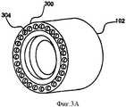
Фиг.3А представляет собой изометрическое изображение кассеты устройства, иллюстрируемого на Фиг.1 и 2, которое показывают со стороны введения шприца;FIG. 3A is an isometric view of the cartridge of the device illustrated in FIGS. 1 and 2, which are shown from the syringe injection side;
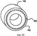
Фиг.3В представляет собой изометрическое изображение кассеты устройства, иллюстрируемого на Фиг.1 и 2, которое показывают со стороны выхода иглы;Fig. 3B is an isometric view of the cartridge of the device illustrated in Figs. 1 and 2, which are shown from the exit side of the needle;
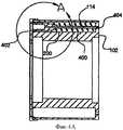
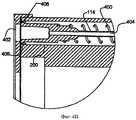
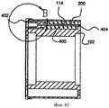
Фиг.4А и 4В представляют собой частичные изображения сбоку в поперечном разрезе кассеты устройства, иллюстрируемого на Фиг.1 и 2, на которых показана единичная полость для иглы в кассете перед вводом иглы в действие;4A and 4B are partial cross-sectional side views of the cartridge of the device illustrated in FIGS. 1 and 2, showing a single cavity for a needle in a cartridge before putting the needle into operation;
Фиг.4С и 4D представляют собой частичные изображения сбоку в поперечном разрезе кассеты устройства, иллюстрируемого на Фиг.1 и 2, на которых показана единичная полость для иглы в кассете во время ввода иглы в действие;Figs. 4C and 4D are partial cross-sectional side views of the cartridge of the device illustrated in Figs. 1 and 2, which show a single cavity for a needle in a cartridge during insertion of a needle;
Фиг.4Е и 4F представляют собой частичные изображения сбоку в поперечном разрезе кассеты устройства, иллюстрируемого на Фиг.1 и 2, на которых показана единичная полость для иглы в кассете после возвращения иглы в кассету;4E and 4F are partial cross-sectional side views of the cartridge of the device illustrated in FIGS. 1 and 2, which show a single needle cavity in a cartridge after the needle is returned to the cartridge;
Фиг.5 представляет собой изометрическое изображение вида снизу кольца предохранителей иглы, которое используют с кассетой устройства, показанного на Фиг.1 и 2;Figure 5 is an isometric image of a bottom view of the needle fuse ring, which is used with the cartridge of the device shown in figures 1 and 2;
Фиг.6 представляет собой схематическое изображение предохранителя от пыли, который используют с кассетой устройства, показанного на Фиг.1 и 2;6 is a schematic illustration of a dust guard that is used with the cartridge of the device shown in FIGS. 1 and 2;
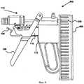
Фиг.7 представляет собой упрощенное изображение сбоку устройства для доставки жидкости, имеющее кассетную ленту для игл, которое создано и функционирует в соответствии с предпочтительным вариантом осуществления настоящего изобретения;FIG. 7 is a simplified side view of a fluid delivery apparatus having a needle cassette tape that is constructed and operates in accordance with a preferred embodiment of the present invention;
Фиг.8 представляет собой упрощенное изображение сбоку устройства для доставки жидкости, имеющее скользящую кассету, которое создано и функционирует в соответствии с предпочтительным вариантом осуществления настоящего изобретения; иFig. 8 is a simplified side view of a fluid delivery device having a sliding cassette that is constructed and operates in accordance with a preferred embodiment of the present invention; and
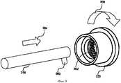
Фиг.9 представляет упрощенную иллюстрацию вращательного механизма, который используют с кассетой устройства, показанного на Фиг.1 и 2.Fig.9 is a simplified illustration of the rotational mechanism that is used with the cartridge of the device shown in Fig.1 and 2.
Подробное описание предпочтительных вариантовDetailed Description of Preferred Options
Обратимся теперь к Фиг.1А и 1В, которые представляют собой упрощенные изображения сбоку устройства 100 для доставки жидкости, созданного и функционирующего в соответствии с предпочтительным вариантом осуществления настоящего изобретения. Показано устройство для доставки жидкости, в целом обозначаемое числом 100, к которому присоединяют кассету 102 для игл. Кассета 102 предпочтительно вмещает множество игл 114, и ее изготавливают таким образом, чтобы монтировать к и демонтировать с устройства 100 для доставки жидкости, например, на стержневом устройстве 116, для которого предусматривают стопорный механизм 104, который может быть любым традиционным стопорным механизмом и который устанавливают или на стержне 116, или на кассете 102 с тем, чтобы кассету 102 можно было надежно прикреплять к стержневому устройству 116. Устройство 100 для доставки жидкости также предпочтительно включает рукоятку 106, предохранительную защелку 108, основной кожух 110 и поршневое устройство, в целом обозначаемое числом 112, которое функционирует в комбинации для того, чтобы выдвигать кассету 102 к следующей игле 114 и пропускать заранее установленное количество жидкости сквозь единичную иглу 114.Turning now to FIGS. 1A and 1B, which are simplified side views of a
Обратимся теперь к Фиг.2А и 2В, которые представляют собой упрощенные изображения сбоку в поперечном разрезе устройства 100 для доставки жидкости, созданного и функционирующего в соответствии с предпочтительным вариантом осуществления настоящего изобретения. На Фиг.2А и 2В кассета 102 для игл представляет собой иллюстрированное помещение множества игл 114, где лишь одна из игл показана для целей иллюстрации, в заранее установленном порядке. Кассета 102 имеет предпочтительно цилиндрическую форму и включает множество полостей 200 для игл, предназначенных для помещения единичных игл 114 стерильным и безопасным способом. В одной из возможных конфигураций двадцать четыре полости для игл, в которых помещаются двадцать четыре иглы, располагаются вдоль окружности кассеты 102. Следует понимать, однако, что кассету 102 можно конструировать таким образом, чтобы она вмещала любое подходящее количество игл. Предпочтительно, игла, находящаяся наиболее высоко в кассете, занимает положение 202 для ввода иглы в действие. В процессе функционирования устройства 100 для доставки жидкости иглу 114, занимающую положение 202 для ввода иглы в действие, выдвигают наружу из кассеты 102, делая возможным, чтобы иглу 114 ввели в тело единичного субъекта, например, для инъекции жидкости. После инъекции иглу 114 отводят назад в ее полость 200 в кассете 102, а кассета 102 поворачивается на заранее установленную величину путем использования любых традиционных средств, чтобы дать возможность неиспользованной игле занять положение 202 для ввода иглы в действие, как это описано более подробно ниже со ссылкой на Фиг.9.Turning now to FIGS. 2A and 2B, which are simplified cross-sectional side views of a
Поршневое устройство 112 предпочтительно включает резервуар 204 для жидкости и первый одноходовой клапан 206 для облегчения вхождения жидкости в резервуар 204, например, сквозь трубку или контейнер, соединяемый с клапаном 206. Поршневое устройство 112 также предпочтительно включает второй одноходовой клапан 208 и шприц 210. Второй одноходовой клапан 208 служит для того, чтобы сделать возможным прохождение жидкости из резервуара 204 в шприц 210. Поршневое устройство 112 предпочтительно включает также поршень 212 со смещенной пружиной, который монтируют с возможностью скольжения в резервуаре 204, и поршневой толкатель 214, соединяемый с поршнем 212 и предназначенный, чтобы на него оказывали давление во время работы устройства 100 для доставки жидкости с тем, чтобы заставлять жидкость течь из резервуара 204 в шприц 210. Во время проведения инъекции шприц 210 временно соединяется с иглой 114 и продвигает ее наружу из положения 202 для ввода иглы в действие таким образом, чтобы игла 114 выступала из кассеты 102 для введения в тело субъекта. Это будет дополнительно описано ниже.The
Основной кожух 110 (Фиг.1А) предпочтительно соединяют с кассетой 102 посредством стержневого устройства 116, и кожух может перемещаться, вместе с кассетой 102, между исходным положением А, как показано на Фиг.2А, и положением В для проведения инъекции, как показано на Фиг.2В. Стержневое устройство 116 предпочтительно включает внутренний стержень 216, наружный стержень 218 и передвижчик 220, соединяемый с кассетой 102 для выдвижения следующей полости 200 для игл в кассете 102 в положение 202 для ввода иглы в действие, например, путем поворота кассеты 102 на заранее установленную величину всякий раз, когда основной кожух 110 перемещают из положения В для проведения инъекции в исходное положение А. Основной кожух 110 включает также пружину 222 основного кожуха, расположенную между наружным стержнем 218 и поршнем 212. В исходном положении А основной кожух 110 и кассета 102 находятся в выдвинутом положении по отношению к поршневому устройству 112, а пружина 222 находится в сжатом состоянии. В положении В для проведения инъекции основной кожух 110 и кассета 102 находятся в отведенном назад положении по отношению к поршневому устройству 112. В положении В для проведения инъекции шприц 210 входит в кассету 102 и соединяется с иглой 114 при положении 202 для ввода иглы в действие. Рукоятка 106 и предохранительная защелка 108 предпочтительно функционируют таким образом, чтобы сделать возможным перемещение основного кожуха 110 и кассеты 102 между исходным положением А и положением В для проведения инъекции.The main casing 110 (Fig. 1A) is preferably connected to the
Рычаг 224 поршня, соединяемый с поршнем 212, предпочтительно приспосабливают таким образом, чтобы отступать вверх в поршневое устройство 112, когда поршень 212 продвигают в направлении стрелки 230, и протягиваться вниз из поршневого устройства 112, когда поступательное перемещение поршня 212 прекращается. Выталкиватель 234 поршня располагают предпочтительно в одной из нескольких выемок 226 на наружном стержне 218 основного кожуха 110, причем каждая выемка 226 соответствует заранее определенной дозировке. После проведения инъекции наружный стержень 218 предпочтительно поступательно перемещается в направлении стрелки 230, где выталкиватель 234 поршня предпочтительно скашивают вниз, чтобы сделать возможным зацепление и прохождение снизу соответствующим образом скошенной верхушки рычага 224 поршня. Наружный стержень 218 затем предпочтительно перемещается назад в направлении стрелки 232, причем выталкиватель 234 поршня захватывает рычаг 224 поршня и отводит поршень 212 назад. Можно будет видеть, что более близкое расположение выталкивателя 234 поршня к резервуару 204 способствует тому, что выталкиватель 234 поршня входит в зацепление с рычагом 224 поршня раньше и большее количество жидкости протекает в резервуар 204, в то время как более отдаленное расположение выталкивателя 234 поршня от резервуара 204 будет способствовать тому, что выталкиватель 234 поршня входит в зацепление с рычагом 224 поршня позже и меньшее количество жидкости попадает в резервуар 204. Таким образом, можно установить положение выталкивателя 234 поршня на желаемой выемке 226 с тем, чтобы определять количество жидкости для каждой инъекции.The
Обычное действие устройства 100 для доставки жидкости начинается путем перемещения толкателя 214 поршня поршневого устройства 112 назад и вперед с тем, чтобы создать пониженное давление в резервуаре 204. Это перемещение продолжается до тех пор, пока жидкость не начнет протекать сквозь трубопровод, соединяющий устройство 100 для доставки жидкости с контейнером для жидкости (не показанным), и поступать в устройство 100 для доставки жидкости через первый одноходовой клапан 206. Желаемую дозировку жидкости, которую будут вводить каждому субъекту, контролируют путем установки рычага 224 поршня в желаемую выемку 226, как описано выше. Кассету 102 для игл можно затем прикреплять к основному кожуху 110.The normal operation of the
Проведение инъекции субъекту осуществляют в три стадии. Вначале рукоятку 106 передвигают в направлении захватывающего приспособления 228. Это приводит к поступательному перемещению основного кожуха 110, наружного стержня 218, внутреннего стержня 216 и кассеты 102 в направлении стрелки 230 в исходное положение А, как видно на Фиг.2А. Поступательное перемещение основного кожуха 110 приводит к сжатию пружины 222 основного кожуха и блокированию предохранительной защелки 108 на наружном стержне 218 основного кожуха 110. Передвижение рукоятки 106 приводит также к тому, что передвижчик 220 выдвигает кассету 102 на заранее установленную величину с тем, чтобы поместить следующую иглу 114 в положение 202 для ввода иглы в действие. Передвижчик 220 может функционировать посредством любого подходящего способа в данной области техники для превращения линейного движения главного кожуха 110 в действие выдвижения кассеты 102, например, посредством вращения. Затем предохранительную защелку 108 вдавливают вниз и высвобождают ее от наружного стержня 218, что приводит к обратному перемещению основного кожуха 110 и кассеты 102 по направлению стрелки 232, как видно на Фиг.2В. Обратное перемещение кассеты 102 заставляет шприц 210 входить в кассету 102, соединяться с иглой 114 в положении 202 для ввода иглы в действие и частично выталкивать иглу 114 из кассеты 102, после чего иглу 114 можно заорем вводить в тело субъекта. Высвобождение предохранительной защелки 108 также предпочтительно заставляет растягиваться пружину 222, приводя к обратному перемещению наружного стержня 218 и поршня 212, что заставляет заранее определенное количество жидкости поступать в резервуар 204 через первый одноходовой клапан 206. На третьей стадии толкатель 214 поршня продвигают вперед, что приводит к прохождению заранее определенного количества жидкости из резервуара 204 в шприц 210 и в иглу 114 для проведения инъекции в тело субъекта. Следует понимать, что на этой стадии открывается второй одноходовой клапан 208, а первый одноходовой клапан 206 закрывается с тем, чтобы привести к перемещению жидкость, как это описано. Вышеописанный процесс повторяют затем для следующих субъектов, причем для каждой инъекции используют неиспользованную иглу.The injection of the subject is carried out in three stages. First, the
Обратимся теперь к Фиг.3А и 3В, на которых представлены альтернативные изометрические изображения кассеты 102, показанной на Фиг.1 и 2, которые даются со стороны 300 ввода шприца и со стороны 302 выхода иглы соответственно. Показана сторона 300 для ввода шприца кассеты 102, которая имеет множество отверстий 304, чтобы дать возможность каждой игле входить в соединение со шприцем 210 (Фиг.2А) в соответствующее время в процессе работы устройства. Показана сторона 302 выхода иглы кассеты 102, которая имеет множество соответствующих отверстий 306 для выхода иглы, чтобы сделать возможным перемещение наружу единичной иглы из кассеты 102 во время ввода иглы в действие.Turning now to FIGS. 3A and 3B, alternative isometric images of the
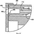
Обратимся теперь к Фиг.4А и 4В, которые представляют собой частичные изображения сбоку в поперечном разрезе кассеты устройства, иллюстрируемого на Фиг.1 и 2, на которых показана единичная полость для иглы в кассете перед вводом иглы в действие, к Фиг.4С и 4D, которые представляют собой частичные изображения сбоку в поперечном разрезе кассеты устройства, иллюстрируемого на Фиг.1 и 2, на которых показана единичная полость для иглы в кассете во время ввода иглы в действие, и к Фиг.4Е и 4F, которые представляют собой частичные изображения сбоку в поперечном разрезе кассеты устройства, иллюстрируемого на Фиг.1 и 2, на которых показана единичная полость для иглы в кассете после возвращения иглы в кассету. Каждая полость 200 для иглы (Фиг.2А) предпочтительно включает пружину 400 для иглы, сцепленную вокруг иглы 114 для облегчения возвращения иглы 114 назад в полость 200 после ее использования. Пружина 400 предпочтительно сжимается со стороны наружной стенки 404 полости 200 для иглы, когда шприц 210 выталкивает иглу 114 из полости 200 для иглы. Когда шприц 210 втягивается, сжимающее усилие снижается, делая возможным, чтобы с помощью пружины 400 игла 114 была возвращена назад в полость 200.Turning now to FIGS. 4A and 4B, which are partial cross-sectional side views of the cartridge of the device illustrated in FIGS. 1 and 2, which show a single cavity for a needle in a cartridge before putting the needle into operation, FIGS. 4C and 4D which are partial cross-sectional side views of the cartridge of the device illustrated in FIGS. 1 and 2, showing a single cavity for a needle in a cartridge during insertion of a needle, and FIGS. 4E and 4F, which are partial images on the side in popper sectional view of the cassette-screw device illustrated in Figures 1 and 2, which show the unit in the cavity of the needle cassette after the return of the needle into the cartridge. Each needle cavity 200 (FIG. 2A) preferably includes a
Первый предохранитель 406 иглы и предпочтительно второй предохранитель 408 иглы располагаются на входе 402 полости 200 для иглы, через которую входит шприц 210. Предохранители 406, 408 иглы функционируют с целью предотвращения повторного использования иглы. Перед первым использованием иглы 114 предохранители иглы 406, 408 изгибают и удерживают на участке между основанием иглы 114 и внутренними стенками полости 200 для иглы, как показано на Фиг.4А и 4В. Когда иглу 114 выдвигают из кассеты 102, предохранители 406, 408 иглы упруго выравниваются, как показано на Фиг.4С и 4D. Это предотвращает дальнейшее использование иглы 114, так как отверстие в полости 200 для иглы в кассете 102 со стороны вхождения жидкости, которое ведет к игле 114, становится действенно блокированным, предотвращая введение шприца 210 в полость 200 для иглы.The
Обратимся теперь к Фиг.5, которая представляет собой изометрическое изображение вида снизу кольца предохранителей игл, которое используется с кассетой устройства, показанного ни Фиг.1 и 2. Показано кольцо 500 предохранителей игл, имеющее серию кольцевых отверстий 502, на которых располагаются первые и вторые предохранители 406, 408 игл. Кольцо 500 предпочтительно устанавливают в кассете 102 со стороны поступления жидкости и каждую полость 200 для иглы снабжают первым и вторым предохранителями 406, 408 иглы. Кольцо 500 можно изготавливать из гибкого пластика или любого другого подходящего материала. На Фиг.5 предохранители 406, 408 игл показаны в виде изогнутой конфигурации.Turning now to FIG. 5, which is an isometric view of a bottom view of a needle fuse ring that is used with the cartridge of the device shown in FIGS. 1 and 2. A
Обратимся теперь к Фиг.6, которая представляет собой схематическое изображение предохранителя от пыли, который используют с кассетой устройства, показанного на Фиг.1 и 2. Показан предохранитель 600 от пыли, имеющий предпочтительно форму кольца и имеющий зазор 602. Предохранитель 600 от пыли предпочтительно прочно прикрепляют к стержневому устройству 116 (Фиг.1А), и он покрывает все отверстия, которые находятся в кассете 102 со стороны поступления жидкости, за исключением отверстия со стороны поступления жидкости, которое ведет к игле, находящейся в положении 202 для ввода иглы в действие (Фиг.2А). Предохранитель 600 от пыли предпочтительно защищает иглы 114 от воздействия частиц, находящихся в воздухе. Тонкое покрытие (не показанное), предпочтительно изготавливаемое из бумаги, можно применять также для покрытия кассеты 102 со стороны проведения инъекции, делая возможным, чтобы иглы 114 протыкали тонкое покрытие, когда они входят в полость 200, одновременно защищая иглы 114 от пыли перед использованием. Тонкое покрытие может также выполнять роль печатных инструкций для использования устройства.Turning now to FIG. 6, which is a schematic illustration of a dust fuse that is used with the cartridge of the device shown in FIGS. 1 and 2. A
Обратимся теперь к Фиг.7, которая представляет собой упрощенное изображение сбоку устройства для доставки жидкости, имеющее кассетную ленту для игл, которое создано и функционирует в соответствии с предпочтительным вариантом осуществления настоящего изобретения. Показано устройство 700 для доставки жидкости, которое функционирует, в основном, аналогичным способом, как и устройство 100 для доставки жидкости, описанное выше, с существенным отличием в том, что используется кассетная лента 702, в которой располагается множество полостей 704 для игл. В отличие от вращения цилиндрической кассеты, устройство 700 для доставки жидкости выдвигает каждую полость 704 для иглы в кассетной ленте 702 в положение 202 для ввода иглы в действие путем использования любого известного механизма. Кассетную ленту 702 можно изготавливать из любого гибкого материала, такого как пластик или ткань.Turning now to FIG. 7, which is a simplified side view of a fluid delivery device having a needle cassette, which is constructed and operates in accordance with a preferred embodiment of the present invention. A
Обратимся теперь к Фиг.8, которая представляет собой упрощенное изображение сбоку устройства для доставки жидкости, имеющее скользящую кассету, которое создано и функционирует в соответствии с предпочтительным вариантом осуществления настоящего изобретения. Показано устройство 800 для доставки жидкости, которое функционирует, в основном, аналогичным способом, как и устройство 100 для доставки жидкости, описанное выше, с существенным отличием в том, что используется скользящая кассета 802, которая приспособлена для скольжения вдоль любой оси, которая перпендикулярна оси стержневого устройства 116.Referring now to FIG. 8, which is a simplified side view of a fluid delivery device having a sliding cassette that is constructed and operates in accordance with a preferred embodiment of the present invention. A
Обратимся теперь к Фиг.9, которая представляет собой упрощенную иллюстрацию вращательного механизма, который используют с кассетой устройства, показанного на Фиг.1 и 2. На Фиг.9 показан внутренний стержень 216 (Фиг.2А), который имеет шип 900, предпочтительно выступающий вниз от конца стержня 216 предельно близко к передвижчику 220, на котором можно монтировать кассету (не показанную). Передвижчик 220 имеет предпочтительно серию зубов 902 зубчатого колеса, предпочтительно располагающихся на его внутренней окружности под углом по отношению к продольной оси стержня 216. Когда стержень 216 перемещается поступательно по направлению стрелки 204, шип 900 входит в зацепление с зубом 902 зубчатого колеса (Фиг.2А), которое, будучи установлено под углом, заставляет передвижчик 220 вращаться в направлении стрелки 906.Turning now to FIG. 9, which is a simplified illustration of the rotary mechanism that is used with the cartridge of the device shown in FIGS. 1 and 2. FIG. 9 shows an inner shaft 216 (FIG. 2A) that has a
Следует понимать, что один или большее количество элементов изобретения, описанного здесь, могут быть исключены или выполнены другим образом, чем это показано, без отклонения от истинной сути и объема изобретения.It should be understood that one or more elements of the invention described herein can be excluded or performed in a different way than shown, without deviating from the true nature and scope of the invention.
В то время как настоящее изобретение описано со ссылкой на один или большее количество специфических вариантов осуществления изобретения, предполагается, что описание является в целом иллюстративным по отношению к изобретению и его не следует рассматривать как ограничивающее изобретение до показанных вариантов. Следует понимать, что у специалистов в данной области могут возникнуть различные модификации, которые, хотя конкретно здесь не показаны, находятся, тем не менее, в пределах истинной сути и объема изобретения.While the present invention has been described with reference to one or more specific embodiments of the invention, it is assumed that the description is generally illustrative in relation to the invention and should not be construed as limiting the invention to the options shown. It should be understood that specialists in this field may experience various modifications, which, although not specifically shown here, are, however, within the true essence and scope of the invention.
Claims (14)
Translated fromRussianApplications Claiming Priority (2)
| Application Number | Priority Date | Filing Date | Title |
|---|---|---|---|
| US47884503P | 2003-06-17 | 2003-06-17 | |
| US60/478,845 | 2003-06-17 |
Publications (2)
| Publication Number | Publication Date |
|---|---|
| RU2005139568A RU2005139568A (en) | 2006-06-10 |
| RU2343937C2true RU2343937C2 (en) | 2009-01-20 |
Family
ID=33551856
Family Applications (1)
| Application Number | Title | Priority Date | Filing Date |
|---|---|---|---|
| RU2005139568/14ARU2343937C2 (en) | 2003-06-17 | 2004-06-17 | Liquid injector equipped with removable needle holder |
Country Status (17)
| Country | Link |
|---|---|
| US (2) | US7361163B2 (en) |
| EP (1) | EP1638629B1 (en) |
| JP (1) | JP2006527622A (en) |
| KR (1) | KR20060034644A (en) |
| CN (1) | CN100462109C (en) |
| AT (1) | ATE460192T1 (en) |
| AU (1) | AU2004246900B2 (en) |
| CA (1) | CA2529484C (en) |
| DE (1) | DE602004025931D1 (en) |
| IL (1) | IL162599A (en) |
| MX (1) | MXPA05013744A (en) |
| NO (1) | NO20060237L (en) |
| NZ (1) | NZ544625A (en) |
| RU (1) | RU2343937C2 (en) |
| TW (1) | TW200618831A (en) |
| WO (1) | WO2004110299A2 (en) |
| ZA (1) | ZA200510327B (en) |
Cited By (1)
| Publication number | Priority date | Publication date | Assignee | Title |
|---|---|---|---|---|
| RU200703U1 (en)* | 2020-03-20 | 2020-11-06 | Общество с ограниченной ответственностью "АТ-ЛИРТ" | LIQUID PUMP FOR CHEMILUMINESCENT MEASUREMENTS FROM AIRCRAFT |
Families Citing this family (54)
| Publication number | Priority date | Publication date | Assignee | Title |
|---|---|---|---|---|
| RU2343937C2 (en)* | 2003-06-17 | 2009-01-20 | Адст Текнолоджис Лтд. | Liquid injector equipped with removable needle holder |
| US8057434B2 (en) | 2004-03-31 | 2011-11-15 | Eli Lilly And Company | Injection apparatus having a needle cassette for delivering a pharmaceutical liquid |
| EP1729919A4 (en)* | 2004-03-31 | 2009-12-23 | Eastland Medical Systems Ltd | Jig |
| KR20070008659A (en)* | 2004-03-31 | 2007-01-17 | 이스트랜드 메디칼 시스템즈 리미티드 | Work head |
| CN100551579C (en)* | 2004-03-31 | 2009-10-21 | 伊斯特兰德医学系统有限公司 | drive unit |
| PT1732627E (en)* | 2004-03-31 | 2010-07-26 | Lilly Co Eli | Injection apparatus having a needle cassette for delivering a pharmaceutical liquid |
| US20070073220A1 (en)* | 2004-10-06 | 2007-03-29 | Philip Bunce | Inoculation device |
| KR20070091304A (en)* | 2005-01-07 | 2007-09-10 | 이스트랜드 메디칼 시스템즈 리미티드 | Jig |
| US20090230635A1 (en)* | 2005-01-07 | 2009-09-17 | Eastland Medical Systems Ltd. | Locating means |
| US7618396B2 (en)* | 2006-08-09 | 2009-11-17 | Avant Medical Corp. | Injection system with hidden needles |
| WO2008066991A2 (en)* | 2006-08-30 | 2008-06-05 | Arthur Harris | Continuous feed hypodermic syringe with self contained cartridge dispenser |
| AU2008222300A1 (en)* | 2007-03-06 | 2008-09-12 | Adst Technologies Ltd. | A rapid injection device |
| US20100152660A1 (en)* | 2007-05-30 | 2010-06-17 | Eli Lilly And Company | Cartridge with multiple injection needles for a medication injection device |
| US9205193B2 (en)* | 2007-06-12 | 2015-12-08 | Peter V. Boesen | Self-contained medication injection system and method |
| US8579861B2 (en)* | 2007-07-28 | 2013-11-12 | Novo Nordisk A/S | Needle magazine |
| WO2009086182A1 (en)* | 2007-12-21 | 2009-07-09 | Carticept Medical, Inc. | Articular injection system |
| US9044542B2 (en) | 2007-12-21 | 2015-06-02 | Carticept Medical, Inc. | Imaging-guided anesthesia injection systems and methods |
| US8545440B2 (en) | 2007-12-21 | 2013-10-01 | Carticept Medical, Inc. | Injection system for delivering multiple fluids within the anatomy |
| WO2010008395A1 (en) | 2008-07-18 | 2010-01-21 | Allpure Technologies, Inc. | Fluid transfer device |
| WO2010048753A1 (en)* | 2008-10-29 | 2010-05-06 | Pan Qiubao | A continuous syringe with automatic replacing needles |
| SI3187219T1 (en) | 2008-12-02 | 2020-09-30 | Allergan, Inc. | Injection device |
| WO2010084113A1 (en) | 2009-01-20 | 2010-07-29 | Novo Nordisk A/S | Drug delivery device with reservoir comprising window coverable by needle magazine |
| DE102009018234A1 (en)* | 2009-04-21 | 2010-12-30 | Burdinski, Luz, Dr.med.vet. | Vaccine syringe for use in veterinary medicine with automatic needle change |
| US9107988B2 (en) | 2010-08-16 | 2015-08-18 | Becton, Dickinson And Company | Circuitous band needle changing apparatus |
| US8876780B2 (en)* | 2010-08-16 | 2014-11-04 | Becton, Dickinson And Company | Attachable needle changing device for medicament delivery device |
| US9125975B2 (en)* | 2010-08-16 | 2015-09-08 | Becton, Dickinson And Company | User-actuated storage assembly for injection device |
| AU2011329876B2 (en)* | 2010-11-19 | 2014-09-18 | Eli Lilly And Company | Needle magazine for medication injection device |
| ITMO20110158A1 (en)* | 2011-06-22 | 2012-12-23 | Lameplast Spa | DEVICE FOR INTRODUCING SUBSTANCES WITHIN ANIMALS |
| EP2604304A1 (en)* | 2011-12-14 | 2013-06-19 | Sanofi-Aventis Deutschland GmbH | Needle storage magazine |
| US9149585B2 (en) | 2012-04-20 | 2015-10-06 | Cook Medical Technologies Llc | Multi-needle injection device |
| EP2668901A1 (en)* | 2012-05-31 | 2013-12-04 | Roche Diagniostics GmbH | Sensor insertion assembly, sensor cartridge, and inserter |
| EP2740503A1 (en)* | 2012-12-07 | 2014-06-11 | Sanofi-Aventis Deutschland GmbH | Needle assembly magazine |
| US20140350518A1 (en) | 2013-05-23 | 2014-11-27 | Allergan, Inc. | Syringe extrusion accessory |
| MX382643B (en) | 2013-12-30 | 2025-03-11 | Phi Tech Animal Health Tech Ltd | INJECTION DEVICES. |
| KR102017563B1 (en)* | 2014-03-20 | 2019-09-03 | (주)아모레퍼시픽 | Injection Device Of Medical Fluid |
| US10029048B2 (en) | 2014-05-13 | 2018-07-24 | Allergan, Inc. | High force injection devices |
| US10226585B2 (en) | 2014-10-01 | 2019-03-12 | Allergan, Inc. | Devices for injection and dosing |
| EP3268063A4 (en) | 2015-03-10 | 2018-10-31 | Allergan Pharmaceuticals Holdings (Ireland) Unlimited Company | Multiple needle injector |
| WO2016147166A2 (en)* | 2015-03-14 | 2016-09-22 | Adst Technologies Ltd. | Mass vaccination device |
| US20190053465A1 (en)* | 2016-02-11 | 2019-02-21 | Somark Innovations Group Pty Ltd | Systems and methods for attaching identification information to an animal |
| WO2017136898A1 (en) | 2016-02-11 | 2017-08-17 | Somark Group Limited | A radio device for implantation in an animal, a method for making a radio device for implantation in an animal, a method for providing electrical power to a radio device attached to an animal, a method for implanting a radio device into an animal, an animal having implanted therein a radio device, and a radio device implanted in an animal |
| US11067430B2 (en) | 2016-02-11 | 2021-07-20 | Somark Group Limited | System and a method for ascertaining the mass of at least one animal |
| US11964136B2 (en) | 2016-04-01 | 2024-04-23 | Merit Medical Systems, Inc. | Medical devices for delivering plugs to voids |
| WO2017176787A1 (en)* | 2016-04-04 | 2017-10-12 | Merit Medical Systems, Inc. | Medical plug delivery devices with a rotatable magazine and related components and methods |
| CN109310827B (en) | 2016-04-08 | 2021-09-07 | 阿勒根公司 | Suction and Injection Devices |
| USD867582S1 (en) | 2017-03-24 | 2019-11-19 | Allergan, Inc. | Syringe device |
| IL270247B2 (en) | 2017-05-01 | 2023-10-01 | Phi Tech Animal Health Tech Ltd | Injection apparatus and method for use |
| WO2019071320A1 (en) | 2017-10-12 | 2019-04-18 | Somark Group Limited | An rfid tag insertion cartridge and an rfid tag insertion tool |
| WO2019116229A1 (en) | 2017-12-11 | 2019-06-20 | Target Point Technologies Ltd. | Intranasal administration device |
| CN110384841B (en)* | 2018-04-18 | 2023-03-31 | 恩贝克塔公司 | Pen type needle assembly device |
| CN110271774B (en)* | 2019-07-02 | 2021-02-02 | 深圳昌恩智能股份有限公司 | Influenza prevention propagation system in bus |
| US11266792B2 (en) | 2019-10-28 | 2022-03-08 | FGC Holdings Limited | Single use safety needle guard |
| CN111282092B (en)* | 2020-02-15 | 2021-11-16 | 湖州师范学院 | Automatic injection intelligent magnetic drive needle mounting mechanism |
| CN112451165B (en)* | 2020-12-16 | 2024-12-13 | 河北农业大学 | A poultry injection device that is convenient for replacing needles |
Citations (3)
| Publication number | Priority date | Publication date | Assignee | Title |
|---|---|---|---|---|
| US5318522A (en)* | 1987-06-08 | 1994-06-07 | Antonio Nicholas F D | Hypodermic fluid dispenser |
| US5829589A (en)* | 1997-09-12 | 1998-11-03 | Becton Dickinson And Company | Pen needle magazine dispenser |
| US6032543A (en)* | 1995-11-02 | 2000-03-07 | Novaseptum Ab | Device for introduction and/or withdrawal of a medium into/from a container |
Family Cites Families (18)
| Publication number | Priority date | Publication date | Assignee | Title |
|---|---|---|---|---|
| US4223674A (en)* | 1978-06-29 | 1980-09-23 | Arthur J. McIntosh | Implant gun |
| US4518384A (en)* | 1983-06-17 | 1985-05-21 | Survival Technology, Inc. | Multiple medicament cartridge clip and medicament discharging device therefor |
| IT208306Z2 (en)* | 1986-09-15 | 1988-05-28 | Ft Group Srl | AUTOMATIC FORMING MACHINE FOR CARDBOARD BOXES. |
| US4857048A (en) | 1987-05-29 | 1989-08-15 | Hewlett-Packard Company | IV pump and disposable flow chamber with flow control |
| US6056716A (en)* | 1987-06-08 | 2000-05-02 | D'antonio Consultants International Inc. | Hypodermic fluid dispenser |
| US5285896A (en)* | 1992-03-25 | 1994-02-15 | Timely Medical Innovations, Ltd. | Apparatus for receiving and capturing a hypodermic needle hub and cannula |
| FR2693112B1 (en) | 1992-07-01 | 1994-09-02 | Raymond Denance | Electromechanical injection device for medical and veterinary use actuated by a trigger. |
| US5672155A (en) | 1996-06-14 | 1997-09-30 | Riley; Robert Q. | Fluid transfer apparatus |
| US6610042B2 (en)* | 1997-12-05 | 2003-08-26 | Felton Medical, Inc. | Disposable unit-dose jet-injection syringe for pre-filled and/or transfilled liquid injectable medical drug or vaccine products and method thereof |
| DE19840856B4 (en)* | 1998-09-07 | 2008-04-10 | Roche Diagnostics Gmbh | System for obtaining a body fluid, lancet magazine, lancet, lancet set, lancing device and method for removing a lancet from a lancet magazine and use of the system |
| AU5824001A (en)* | 2000-06-09 | 2001-12-17 | Novo Nordisk A/S | A needle magazine |
| US7005040B2 (en)* | 2000-09-05 | 2006-02-28 | Astenjohnson, Inc. | Fabric support element for a papermaking machine |
| US7916013B2 (en) | 2005-03-21 | 2011-03-29 | Greatbatch Ltd. | RFID detection and identification system for implantable medical devices |
| US7041068B2 (en)* | 2001-06-12 | 2006-05-09 | Pelikan Technologies, Inc. | Sampling module device and method |
| US20030105430A1 (en) | 2001-11-30 | 2003-06-05 | Elan Pharma International Limited Wil House | Automatic injector |
| EP1556103A1 (en)* | 2002-10-07 | 2005-07-27 | Novo Nordisk A/S | Needle device comprising a plurality of needles |
| RU2343937C2 (en) | 2003-06-17 | 2009-01-20 | Адст Текнолоджис Лтд. | Liquid injector equipped with removable needle holder |
| SE528760C2 (en) | 2005-05-18 | 2007-02-13 | Secure Logistics Sweden Ab | Method and apparatus for detecting intrusion into or manipulation of the contents of an enclosure |
- 2004
- 2004-06-17RURU2005139568/14Apatent/RU2343937C2/ennot_activeIP Right Cessation
- 2004-06-17NZNZ544625Apatent/NZ544625A/ennot_activeIP Right Cessation
- 2004-06-17WOPCT/IL2004/000526patent/WO2004110299A2/enactiveApplication Filing
- 2004-06-17ZAZA200510327Apatent/ZA200510327B/enunknown
- 2004-06-17CACA2529484Apatent/CA2529484C/ennot_activeExpired - Fee Related
- 2004-06-17KRKR1020057024126Apatent/KR20060034644A/ennot_activeCeased
- 2004-06-17EPEP04744867Apatent/EP1638629B1/ennot_activeExpired - Lifetime
- 2004-06-17AUAU2004246900Apatent/AU2004246900B2/ennot_activeCeased
- 2004-06-17JPJP2006516802Apatent/JP2006527622A/enactivePending
- 2004-06-17MXMXPA05013744Apatent/MXPA05013744A/enactiveIP Right Grant
- 2004-06-17ILIL162599Apatent/IL162599A/enactiveIP Right Grant
- 2004-06-17DEDE602004025931Tpatent/DE602004025931D1/ennot_activeExpired - Lifetime
- 2004-06-17USUS10/868,764patent/US7361163B2/ennot_activeExpired - Fee Related
- 2004-06-17ATAT04744867Tpatent/ATE460192T1/ennot_activeIP Right Cessation
- 2004-06-17CNCNB2004800236818Apatent/CN100462109C/ennot_activeExpired - Fee Related
- 2004-12-14TWTW093138810Apatent/TW200618831A/enunknown
- 2006
- 2006-01-16NONO20060237Apatent/NO20060237L/ennot_activeApplication Discontinuation
- 2008
- 2008-03-06USUS12/043,273patent/US8529522B2/ennot_activeExpired - Fee Related
Patent Citations (3)
| Publication number | Priority date | Publication date | Assignee | Title |
|---|---|---|---|---|
| US5318522A (en)* | 1987-06-08 | 1994-06-07 | Antonio Nicholas F D | Hypodermic fluid dispenser |
| US6032543A (en)* | 1995-11-02 | 2000-03-07 | Novaseptum Ab | Device for introduction and/or withdrawal of a medium into/from a container |
| US5829589A (en)* | 1997-09-12 | 1998-11-03 | Becton Dickinson And Company | Pen needle magazine dispenser |
Cited By (1)
| Publication number | Priority date | Publication date | Assignee | Title |
|---|---|---|---|---|
| RU200703U1 (en)* | 2020-03-20 | 2020-11-06 | Общество с ограниченной ответственностью "АТ-ЛИРТ" | LIQUID PUMP FOR CHEMILUMINESCENT MEASUREMENTS FROM AIRCRAFT |
Also Published As
| Publication number | Publication date |
|---|---|
| CN100462109C (en) | 2009-02-18 |
| JP2006527622A (en) | 2006-12-07 |
| AU2004246900A1 (en) | 2004-12-23 |
| US8529522B2 (en) | 2013-09-10 |
| US20080154235A1 (en) | 2008-06-26 |
| WO2004110299A3 (en) | 2005-06-30 |
| US7361163B2 (en) | 2008-04-22 |
| EP1638629A4 (en) | 2008-04-23 |
| DE602004025931D1 (en) | 2010-04-22 |
| AU2004246900B2 (en) | 2010-02-18 |
| EP1638629A2 (en) | 2006-03-29 |
| ATE460192T1 (en) | 2010-03-15 |
| TW200618831A (en) | 2006-06-16 |
| IL162599A0 (en) | 2005-11-20 |
| IL162599A (en) | 2012-10-31 |
| CN1835773A (en) | 2006-09-20 |
| NZ544625A (en) | 2008-09-26 |
| US20040260270A1 (en) | 2004-12-23 |
| RU2005139568A (en) | 2006-06-10 |
| CA2529484A1 (en) | 2004-12-23 |
| CA2529484C (en) | 2013-02-19 |
| WO2004110299A2 (en) | 2004-12-23 |
| KR20060034644A (en) | 2006-04-24 |
| ZA200510327B (en) | 2007-03-28 |
| MXPA05013744A (en) | 2006-06-27 |
| NO20060237L (en) | 2006-03-01 |
| EP1638629B1 (en) | 2010-03-10 |
Similar Documents
| Publication | Publication Date | Title |
|---|---|---|
| RU2343937C2 (en) | Liquid injector equipped with removable needle holder | |
| JP6931105B2 (en) | Automatic drug delivery device | |
| KR101751719B1 (en) | Reusable auto-injector | |
| RU2624341C2 (en) | Automated injector with separate needle insertion | |
| JP5165381B2 (en) | Safety syringe | |
| DE69429918T2 (en) | RECHARGEABLE, AUTOMATIC OR MANUALLY OPERABLE EMERGENCY INJECTION SYSTEM | |
| DE69934773T2 (en) | Device for administering medicaments | |
| KR880000847B1 (en) | Tablet syringe | |
| EA010513B1 (en) | Injection device | |
| US8372043B2 (en) | Devices and methods for fluid administration | |
| EP2095838A2 (en) | Ampule for needle-less injector | |
| US8702658B2 (en) | IV catheter insertion device and method | |
| ES2589254T3 (en) | Medical fluid management system with reusable RFID accessory | |
| HUP0103213A2 (en) | Actuator for needleless syringe | |
| JP2012516168A (en) | Cartridge and drug delivery device | |
| CN110099709A (en) | Needle insertion and cam mechanism | |
| EP1825878B1 (en) | System for administering a medicament comprising a plunger with a passage for flushing | |
| KR100567783B1 (en) | Safe injection device for liquid or semisolid compositions | |
| TWI566801B (en) | Medicament delivery device | |
| KR20160107056A (en) | Anesthesia liquid injector | |
| CZ2008102A3 (en) | Three-chamber automatic injector | |
| CN104941034A (en) | Improved medical injector system | |
| MXPA00003873A (en) | Preloadable syringe for automated dispensing device |
Legal Events
| Date | Code | Title | Description |
|---|---|---|---|
| MM4A | The patent is invalid due to non-payment of fees | Effective date:20190618 |