RU2338237C1 - Methanol distributor unit - Google Patents
Methanol distributor unitDownload PDFInfo
- Publication number
- RU2338237C1 RU2338237C1RU2007124257/06ARU2007124257ARU2338237C1RU 2338237 C1RU2338237 C1RU 2338237C1RU 2007124257/06 ARU2007124257/06 ARU 2007124257/06ARU 2007124257 ARU2007124257 ARU 2007124257ARU 2338237 C1RU2338237 C1RU 2338237C1
- Authority
- RU
- Russia
- Prior art keywords
- methanol
- flanges
- control valves
- distribution unit
- unit
- Prior art date
Links
- OKKJLVBELUTLKV-UHFFFAOYSA-NMethanolChemical compoundOCOKKJLVBELUTLKV-UHFFFAOYSA-N0.000titleclaimsabstractdescription219
- VNWKTOKETHGBQD-UHFFFAOYSA-NmethaneChemical compoundCVNWKTOKETHGBQD-UHFFFAOYSA-N0.000claimsabstractdescription10
- 238000009826distributionMethods0.000claimsdescription58
- 238000003466weldingMethods0.000claimsdescription16
- 238000004886process controlMethods0.000claimsdescription5
- 230000000712assemblyEffects0.000abstract2
- 238000000429assemblyMethods0.000abstract2
- 230000000694effectsEffects0.000abstract1
- 238000000034methodMethods0.000abstract1
- 239000000126substanceSubstances0.000abstract1
- 239000003112inhibitorSubstances0.000description6
- 239000007789gasSubstances0.000description3
- 230000033228biological regulationEffects0.000description2
- JEIPFZHSYJVQDO-UHFFFAOYSA-Niron(III) oxideInorganic materialsO=[Fe]O[Fe]=OJEIPFZHSYJVQDO-UHFFFAOYSA-N0.000description2
- 230000015572biosynthetic processEffects0.000description1
- 239000012530fluidSubstances0.000description1
- 230000005764inhibitory processEffects0.000description1
- 238000009434installationMethods0.000description1
- 238000004519manufacturing processMethods0.000description1
- 238000005259measurementMethods0.000description1
- 239000012528membraneSubstances0.000description1
- 238000005065miningMethods0.000description1
- 239000003345natural gasSubstances0.000description1
- 238000011022operating instructionMethods0.000description1
- 238000002360preparation methodMethods0.000description1
Images


Landscapes
- Pipeline Systems (AREA)
Abstract
Description
Translated fromRussianИзобретение относится к области механики, а именно к техническим трубопроводам, и может быть использовано в добывающей промышленности, в частности, для автоматического дозирования ингибитора гидратообразования, нагнетаемого в ряд трубопроводов природного газа для предупреждения и ликвидации в них гидратообразования.The invention relates to the field of mechanics, namely to technical pipelines, and can be used in the mining industry, in particular, for automatic dosing of a hydrate inhibitor injected into a number of natural gas pipelines to prevent and eliminate hydrate formation in them.
Известен блок дозирования ингибитора ИНГ 2 Ца 3.620.021, применяемый для ручного и автоматического регулирования расхода ингибитора, в частности метанола, в 6 точек ввода (Каталог продукции «НПО «Промавтоматика»).The known block of dosage of the inhibitor ING 2 CA 3.620.021, used for manual and automatic control of the flow of the inhibitor, in particular methanol, at 6 points of entry (Product catalog "NPO Promavtomatika").
Известна панель распределения ингибитора ПРИ-350, примененная в обустройстве Ямбургского месторождения газа, позволявшая ингибировать 12 точек, а также регулировать подачу в ручном режиме по заданию оператора (Техническое описание и инструкция по эксплуатации Саратовского филиала СКБ ВНПО «Союзгазавтоматика»).The known distribution panel of the PRI-350 inhibitor used in the arrangement of the Yamburgskoye gas field, which made it possible to inhibit 12 points, as well as regulate the supply in manual mode according to the operator’s instructions (Technical description and operating instructions for the Saratov branch of SKB VNPO Soyuzgazavtomatika).
Однако в данных конструкциях отсутствуют средства для измерения расхода ингибитора, а также надежные регуляторы расхода и отсекатели. Также в этих конструкциях отсутствует реальная возможность дистанционного регулирования расхода ингибитора, в частности подачи метанола, на каждую точку ингибирования индивидуально в зависимости от текущих параметров газа. Например, на одну точку осуществляется постоянная подача расчетного количества, а на вторую - подача в дискретном режиме (через определенные интервалы) или подача при необходимости, например, в межпромысловый коллектор.However, in these designs there are no means for measuring the flow rate of the inhibitor, as well as reliable flow controllers and shutoffs. Also, in these designs there is no real possibility of remote control of the inhibitor flow rate, in particular, methanol supply, for each inhibition point individually, depending on the current gas parameters. For example, for one point, the calculated quantity is continuously supplied, and for the second - in discrete mode (at certain intervals) or if necessary, for example, in the infield collector.
Для обеспечения работы промысла и в зависимости от его технологических особенностей совокупность блоков может быть в любом количестве.To ensure the operation of the field and depending on its technological features, the set of blocks can be in any quantity.
Задачей изобретения является разработка конструкции блока распределения метанола, позволяющей:The objective of the invention is to develop the design of a methanol distribution unit, allowing:
- измерять заданное количество метанола в реальном времени с помощью замерного устройства;- measure a given amount of methanol in real time using a measuring device;
- регулировать при отклонениях от заданного количества;- adjust for deviations from a given amount;
- интегрировать данную систему в общепромысловую автоматическую станцию управления технологическими процессами (АСУТП), используя совокупность замера и регулирования в реальном времени;- integrate this system into a general-purpose automatic process control station (APCS) using a combination of real-time metering and regulation;
- подавать метанол в две точки ввода, каждая из которых является автономной.- submit methanol to two entry points, each of which is autonomous.
Поставленная задача достигается тем, что блок распределения метанола состоит из шести узлов блока распределения метанола, четыре из которых включают в себя шесть коллекторов, снабженных задвижками. Блок распределения метанола характеризуется тем, что он снабжен двумя регулирующими клапанами, двумя регулирующими клапанами с приводами, комплектом расходомера. Первый и второй узлы блока распределения метанола свободными концами переходников соединены с комплектом расходомера и фланцами регулирующих клапанов. Третий и четвертый узлы блока распределения метанола двумя свободными фланцами соединены с фланцами регулирующих клапанов с приводами, а двумя другими - с фланцами регулирующих клапанов. Два пятых узла блока распределения метанола соединены своими фланцами с фланцами регулирующих клапанов с приводами, а свободными концами труб с комплектом расходомера. При этом свободные концы тройников первого и второго узлов блока распределения метанола соединены с общепромысловой системой метанопроводов и автоматической станцией управления технологическими процессами. Блок распределения метанола снабжен стойкой и стойкой с поддоном, включающей в себя вертикальные опоры, горизонтальные опоры, направляющие, поддон и трубу, и составные части стойки соединены между собой посредством сварки, при этом стойка соединена со стойкой с поддоном при помощи сварки.The problem is achieved in that the methanol distribution unit consists of six nodes of the methanol distribution unit, four of which include six collectors equipped with valves. The methanol distribution unit is characterized in that it is equipped with two control valves, two control valves with actuators, a flowmeter kit. The first and second nodes of the methanol distribution unit with the free ends of the adapters are connected to the flowmeter set and control valve flanges. The third and fourth nodes of the methanol distribution unit are connected by two free flanges to the flanges of the control valves with actuators, and the other two with the flanges of the control valves. Two fifths of the methanol distribution unit are connected by their flanges to the flanges of the control valves with actuators, and the free ends of the pipes with a flowmeter kit. At the same time, the free ends of the tees of the first and second nodes of the methanol distribution unit are connected to a general field methane piping system and an automatic process control station. The methanol distribution unit is equipped with a stand and a stand with a pallet, including vertical supports, horizontal supports, guides, a pallet and a pipe, and the components of the rack are interconnected by welding, while the rack is connected to the rack with the pallet by welding.
Изобретение поясняется подробным описанием и чертежами, на которых:The invention is illustrated by a detailed description and drawings, in which:
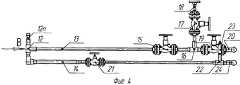
Фиг.1 изображает общий вид блока распределения метанола;Figure 1 depicts a General view of the distribution block of methanol;
Фиг.2 изображает вид А блока распределения метанола;Figure 2 depicts a view A of a methanol distribution unit;
Фиг.3 изображает вид Б блока распределения метанола;Figure 3 depicts a view B of a methanol distribution unit;
Фиг.4 изображает узел 1 блока распределения метанола;Figure 4 depicts a
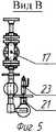
Фиг.5 изображает вид В узла 1 блока распределения метанола;Figure 5 depicts a view In the
Фиг.6 изображает узел 2 блока распределения метанола;6 depicts a node 2 of a methanol distribution unit;
Фиг.7 изображает вид Г узла 2 блока распределения метанола;7 depicts a view G of the node 2 of the methanol distribution unit;
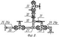
Фиг.8 изображает узлы 3 и 4 блока распределения метанола;Fig. 8 depicts
Фиг.9 изображает узлы 5 и 5а блока распределения метанола;Fig.9 depicts the
Фиг.10 изображает стойку блока распределения метанола;Figure 10 depicts the rack block distribution of methanol;
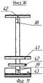
Фиг.11 изображает вид Ж стойки блока распределения метанола;11 depicts a view of the rack R of the methanol distribution unit;
Фиг.12 изображает разрез Е-Е стойки блока распределения метанола.12 is a cross-sectional view EE of a methanol distribution unit strut.
Блок распределения метанола состоит из шести узлов блока распределения метанола 1, 2, 3, 4, 5, 5а (Фиг.1, 2), двух регулирующих клапанов 6 и 6а, двух регулирующих клапанов с приводами 7 и 7а, комплекта расходомера 8, состоящего из двух секций, стоек 9 и стойки с поддоном 10 (Фиг 1, 3).The methanol distribution unit consists of six nodes of the
Первый узел блока распределения метанола 1 (фиг.1) включает в себя коллектор 12 (Фиг.4), выполненный в виде соединенных при помощи сварки между собой переходника 12п и тройника, отводной конец которого соединен с коллектором 13, представляющим собой соединенные при помощи сварки трубу и фланец. Второй конец тройника коллектора 12 соединен с коллектором 14, выполненным в виде соединенных последовательно отвода, трубы, переходника и фланца. Фланец коллектора 13 соединен с помощью шпилек и гаек с фланцем задвижки 15, последняя соединена также при помощи шпилек и гаек с коллектором 16, выполненным в виде соединенных между собой фланца, отрезка трубы, тройника, отводной конец которого соединен с отрезком трубы, последняя соединена с фланцем, свободный конец тройника коллектора 16 соединен с фланцем. Фланец, расположенный над тройником, соединен при помощи шпилек и гаек с задвижкой 17 (Фиг. 4, 5), последняя соединена также при помощи шпилек и гаек с коллектором 18 (Фиг. 4), выполненным из последовательно соединенных при помощи сварки фланца, отрезка трубы и фланца. Фланец, соединенный со свободным концом тройника коллектора 13, соединен при помощи шпилек и гаек с фланцем задвижки 19, второй фланец которой соединен с тройником 20 (Фиг.1, 3). Последний одним свободным концом соединен с трубой 11. Фланец коллектора 14 соединен с фланцем задвижки 21 (Фиг. 4, 5) при помощи шпилек и гаек, второй фланец задвижки 21 соединен с фланцем коллектора 22, выполненным в виде последовательно соединенных фланца, трубы, тройника. Отводной конец последнего соединен со сферическим краном 23. Свободный конец тройника коллектора 22 (Фиг.4) соединен с тройником 24, последний соединен с трубой 11а.The first node of the methanol distribution unit 1 (Fig. 1) includes a collector 12 (Fig. 4) made in the form of an adapter 12p and a tee connected by welding, the outlet end of which is connected to a
Коллектор 14а (Фиг.6, 7) узла 2 (Фиг. 1, 2) выполнен как и коллектор 14 (Фиг.4) узла 1 блока распределения метанола (Фиг.1) из отвода и трубы, но соединены они между собой таким образом, что узел 2 блока распределения метанола (Фиг.2) является симметричным узлу 1 относительно продольной оси блока распределения метанола. Все остальные части узла 2-12а, 13а, 15а-24а (Фиг. 6, 7) соединены между собой также, как и в узле 1 (Фиг. 4, 5).The collector 14a (Fig. 6, 7) of the assembly 2 (Fig. 1, 2) is made like the collector 14 (Fig. 4) of the
Переходники 12п и 12ап коллекторов 12 и 12а (Фиг.4, 6) соединены с комплектом расходомера 8 (Фиг.1), например расходомер-счетчик ультразвуковой электронный двухканальный УРВС-520, производства ЗАО «Взлет». На приборе имеется 4-канальный модуль логических выходов. Расходомер измеряет средний объем расхода и объем жидкости в напорных трубопроводах. По каждому каналу производятся измерения, и на внешние интерфейсы выдается информация.Adapters 12p and 12ap of the
Узел 3 (Фиг.1, 2) блока распределения метанола состоит из коллектора 25 (Фиг.8), выполненного в виде соединенных при помощи сварки последовательно фланца, трубы и фланца, последний соединен при помощи шпилек и гаек с фланцем задвижки 26, второй фланец которой также при помощи шпилек и гаек соединен с фланцем коллектора 27, выполненным в виде соединенных последовательно фланца, трубы и тройника, свободный конец которого соединен с фланцем. Последний при помощи шпилек и гаек соединен с фланцем задвижки 28, которая в свою очередь соединена с коллектором 29, выполненным в виде соединенных между собой фланца, отвода и фланца. Отводной конец тройника коллектора 27 соединен с тройником 30, последний своим отводным концом соединен с краном сферическим, а свободным концом с фланцем затвора обратного поворотного 32. Последний в свою очередь соединен с задвижкой 33, снабженной ответными фланцами.The node 3 (Fig. 1, 2) of the methanol distribution unit consists of a collector 25 (Fig. 8) made in the form of a flange, a pipe and a flange connected by welding, the latter is connected by means of studs and nuts to the
Узел 4 (Фиг.2) блока распределения метанола имеет конструкцию, идентичную конструкции узла 3 (Фиг.2, 8) блока распределения метанола.The node 4 (Figure 2) of the methanol distribution unit has a design identical to that of the node 3 (Figure 2, 8) of the methanol distribution unit.
Фланцы 29 и 29а (Фиг.8) третьего и четвертого узлов блока распределения метанола соединены с фланцами регулирующих клапанов 6 и 6а (Фиг.1, 2), например регулирующие клапаны с ручным приводом типа РК-Р производства ЗАО «Руст 95». Фланцы коллекторов 25 и 25а (Фиг.8) соединены с фланцами регулирующих клапанов с приводами 7 и 7а (Фиг.1, 2), например регулирующие клапаны с мембранными пневмоприводами и электропневматическими позиционерами типа РК производства ЗАО «Руст 95», которые предназначены для непрерывного изменения потока регулируемой среды.The flanges 29 and 29a (Fig. 8) of the third and fourth nodes of the methanol distribution unit are connected to the flanges of the
Узлы 5 и 5а (Фиг.1, 2) выполнены из последовательно соединенных при помощи сварки трубы, отвода, трубы и фланца.The
Фланцы коллекторов 35 и 35а (Фиг.9) двух пятых узлов блока распределения метанола 5 и 5а соединены с фланцами регулирующих клапанов с приводами 7 и 7а (Фиг.2). Свободные концы труб коллекторов 35 (Фиг.9) соединены с комплектом расходомера 8 (Фиг.1).The flanges of the manifolds 35 and 35a (FIG. 9) of the two fifth nodes of the
Стойка 9 (Фиг.1) представляет собой вертикальную опору, соединенную при помощи сварки с поддоном 43 (Фиг.10) стойки 10.The rack 9 (Figure 1) is a vertical support connected by welding with the pallet 43 (Figure 10) of the rack 10.
Стойка с поддоном 10 (Фиг.1) выполнена из вертикальных опор 36, 37 (Фиг.10, 12), горизонтальных опор 38, 39 и направляющих 40, 40а, 41, 41а, 42, 42а поддона 43 и трубы 44. Составные части стойки соединены между собой посредством сварки.The rack with the pallet 10 (Fig. 1) is made of
Блок распределения метанола монтируется в технологическом цехе следующим образом.The methanol distribution unit is mounted in the technological workshop as follows.
Первый блок распределения метанола 1 (Фиг.4) и второй блок распределения метанола 2 (Фиг.6) устанавливаются на стойку 9 (Фиг.1) и направляющие 41, 42, 41a, 42a стойки с поддоном 10 (Фиг.1, 10, 11), и расположены первый 1 и второй 2 блоки распределения метанола симметрично относительно его продольной оси (Фиг.2).The first methanol distribution unit 1 (FIG. 4) and the second methanol distribution unit 2 (FIG. 6) are mounted on the rack 9 (FIG. 1) and the
Третий 3 и четвертый 4 узлы блока распределения метанола (Фиг.8) устанавливаются на направляющие 42 и 42a стойки с поддоном 10 (Фиг.1, 10).The third 3 and fourth 4 nodes of the methanol distribution unit (Fig. 8) are installed on
После чего третий 3 и четвертый 4 узлы блока распределения метанола (Фиг.8) соединяются фланцами коллекторов 29 с входными фланцами двух регулирующих клапанов 6 (Фиг.1) при помощи шпилек и гаек. А первый 1 и второй 2 узлы блока распределения метанола (Фиг.4) фланцами коллекторов 18 и 18а соединены также при помощи шпилек и гаек с выходными фланцами двух регулирующих клапанов 6 (Фиг.1).Then the third 3 and fourth 4 nodes of the methanol distribution unit (Fig. 8) are connected by the flanges of the manifolds 29 to the inlet flanges of the two control valves 6 (Fig. 1) with the help of studs and nuts. And the first 1 and second 2 nodes of the methanol distribution unit (Figure 4) are connected by flanges of the
Пятые узлы 5 и 5а блока распределения метанола (Фиг.2) соединяются своими фланцами при помощи шпилек и гаек с фланцами коллекторов 25 (Фиг.8) третьего 3 и четвертого 4 узлов блока распределения метанола (Фиг.1, 2).The
Переходники 12п и 12ап коллекторов 12 и 12а (Фиг.4, 6) первого 1 и второго 2 узлов блока распределения метанола (Фиг.1, 2) и трубы (Фиг.9) пятых 5 и 5а (Фиг.1, 2) узлов блока распределения метанола соединяются с комплектом расходомера 8 (Фиг.1) при помощи сварки.Adapters 12p and 12ap of the
Фланцы 29 и 29а (Фиг.8) третьего и четвертого узлов блока распределения метанола соединяются с фланцами регулирующих клапанов 6 и 6а (Фиг.1, 2) при помощи шпилек и гаек. Фланцы коллекторов 25 и 25а (Фиг.8) соединяются с фланцами регулирующих клапанов с приводами 7 и 7а (Фиг.1, 2) при помощи шпилек и гаек.The flanges 29 and 29a (Fig. 8) of the third and fourth nodes of the methanol distribution unit are connected to the flanges of the
Фланцы коллекторов 35 и 35а (Фиг.9) двух пятых узлов блока распределения метанола 5 и 5а соединяются с фланцами регулирующих клапанов с приводами 7 и 7а (Фиг.2) при помощи шпилек и гаек. Свободные концы труб коллекторов 35 (Фиг.9) соединены с комплектом расходомера 8 (Фиг.1) при помощи сварки.The flanges of the manifolds 35 and 35a (FIG. 9) of the two fifth nodes of the
Тройники 20 и 20а (Фиг.4, 6) первого и второго блоков распределения метанола соединяются одним из своих отводных концов при помощи сварки с трубой 11 (Фиг.3), а тройники 24 и 24а (Фиг.4, 6) первого и второго блоков распределения метанола соединяются одним из своих отводных концов при помощи сварки с трубой 11a (Фиг.3).
После завершения монтажа блока распределения метанола в технологическом цехе блок распределения метанола свободными отводными концами тройников 20, 20а, 24 и 24а первого и второго узлов блока распределения метанола и свободными концами тройников трубы 44 соединяется при помощи сварки с общепромысловой системой метанопроводов через блок фильтров (система АСУТП).After the installation of the methanol distribution unit in the technological workshop is completed, the methanol distribution unit with the free branch ends of the
Количество блоков определяется исходя из количества точек ввода метанола, необходимого для поддержания безгидратного режима добычи, подготовки и транспортировки газа.The number of blocks is determined based on the number of methanol entry points needed to maintain a non-hydrate mode of gas production, preparation and transportation.
В описанном блоке присутствуют два устройства, встраиваемые в АСУТП и работающие по определенному алгоритму благодаря подаваемым на их органы управления электронным импульсам. Также присутствует регулирующий клапан с ручным приводом, так как блок является системой, работающей в автономном режиме, но с дублирующей ветвью ручной регулировки, повышающей надежность работы блока в целом.In the described block there are two devices built into the process control system and working according to a certain algorithm due to the electronic pulses supplied to their control elements. There is also a control valve with a manual actuator, since the unit is a system that works autonomously, but with a redundant branch of manual adjustment, which increases the reliability of the unit as a whole.
Разработанная конструкция блока распределения метанола позволяет измерить заданное количество метанола в реальном времени с помощью замерного устройства, регулировать количество подачи метанола при отклонениях от заданных параметров, а также подавать метанол в две точки ввода, каждая из которых является автономной.The developed design of the methanol distribution unit allows you to measure a given amount of methanol in real time using a metering device, adjust the amount of methanol supply at deviations from the set parameters, and also supply methanol to two input points, each of which is autonomous.
Кроме того, данная конструкция позволяет интегрировать данную систему в общепромысловую автоматическую станцию управления технологическими процессами (АСУТП), используя совокупность замера и регулирования в реальном времени.In addition, this design allows you to integrate this system into a general-purpose automatic process control station (APCS) using a combination of real-time metering and regulation.
Claims (1)
Translated fromRussianPriority Applications (1)
| Application Number | Priority Date | Filing Date | Title |
|---|---|---|---|
| RU2007124257/06ARU2338237C1 (en) | 2007-06-27 | 2007-06-27 | Methanol distributor unit |
Applications Claiming Priority (1)
| Application Number | Priority Date | Filing Date | Title |
|---|---|---|---|
| RU2007124257/06ARU2338237C1 (en) | 2007-06-27 | 2007-06-27 | Methanol distributor unit |
Publications (1)
| Publication Number | Publication Date |
|---|---|
| RU2338237C1true RU2338237C1 (en) | 2008-11-10 |
Family
ID=40230444
Family Applications (1)
| Application Number | Title | Priority Date | Filing Date |
|---|---|---|---|
| RU2007124257/06ARU2338237C1 (en) | 2007-06-27 | 2007-06-27 | Methanol distributor unit |
Country Status (1)
| Country | Link |
|---|---|
| RU (1) | RU2338237C1 (en) |
Cited By (1)
| Publication number | Priority date | Publication date | Assignee | Title |
|---|---|---|---|---|
| RU2574159C2 (en)* | 2014-05-28 | 2016-02-10 | Общество с ограниченной ответственностью Финансово-промышленная компания "Космос-Нефть-Газ" | Hydrate growth inhibitor delivery method |
Citations (4)
| Publication number | Priority date | Publication date | Assignee | Title |
|---|---|---|---|---|
| SU1308995A1 (en)* | 1985-12-17 | 1987-05-07 | Специальное проектно-конструкторское бюро "Промавтоматика" | Device for introducing hydrate generation inhibitor in gas flow |
| SU1556706A1 (en)* | 1988-03-28 | 1990-04-15 | Научно-Производственное Объединение "Промавтоматика" | Automatic system for controlling the process of inhibition of gas hydration |
| US5209300A (en)* | 1992-02-04 | 1993-05-11 | Ayres Robert N | Pressure regulated chemical injection system |
| RU2242784C2 (en)* | 2002-11-25 | 2004-12-20 | ОАО "НПО "Промавтоматика" | System for distribution of inhibitor of hydro-forming among cluster wells |
- 2007
- 2007-06-27RURU2007124257/06Apatent/RU2338237C1/ennot_activeIP Right Cessation
Patent Citations (4)
| Publication number | Priority date | Publication date | Assignee | Title |
|---|---|---|---|---|
| SU1308995A1 (en)* | 1985-12-17 | 1987-05-07 | Специальное проектно-конструкторское бюро "Промавтоматика" | Device for introducing hydrate generation inhibitor in gas flow |
| SU1556706A1 (en)* | 1988-03-28 | 1990-04-15 | Научно-Производственное Объединение "Промавтоматика" | Automatic system for controlling the process of inhibition of gas hydration |
| US5209300A (en)* | 1992-02-04 | 1993-05-11 | Ayres Robert N | Pressure regulated chemical injection system |
| RU2242784C2 (en)* | 2002-11-25 | 2004-12-20 | ОАО "НПО "Промавтоматика" | System for distribution of inhibitor of hydro-forming among cluster wells |
Non-Patent Citations (1)
| Title |
|---|
| ПАНЕЛЬ АВТОМАТИЧЕСКОГО РАСПРЕДЕЛЕНИЯ ИНГИБИТОРА КОРРОЗИИ ПРИ-350, Техническое описание и инструкция по эксплуатации Саратовского филиала СКБ ВНПО "Союзгазавтоматика", 1987.* |
Cited By (1)
| Publication number | Priority date | Publication date | Assignee | Title |
|---|---|---|---|---|
| RU2574159C2 (en)* | 2014-05-28 | 2016-02-10 | Общество с ограниченной ответственностью Финансово-промышленная компания "Космос-Нефть-Газ" | Hydrate growth inhibitor delivery method |
Similar Documents
| Publication | Publication Date | Title |
|---|---|---|
| AU598325B2 (en) | Mass flowmeter apparatus | |
| US20130233424A1 (en) | Liquid distributor of modular construction | |
| KR100782155B1 (en) | Gas flow measurement device for flowmeter calibration | |
| CN103754815A (en) | Drug adding device and drug adding method both convenient for drug metering and adjusting | |
| CN104359521B (en) | A kind of Large Copacity tank volume detecting system and scaling method | |
| RU127809U1 (en) | DISTRIBUTION AND DOSING SYSTEM FOR HYDRATE FORMATION INHIBITOR | |
| RU2338237C1 (en) | Methanol distributor unit | |
| CN102121846A (en) | Method and device for testing vibration effect of multi-combination hydraulic long pipeline system | |
| BRPI1101865B1 (en) | assembly with valves for installations for measuring liquid products, such as chemicals and auxiliary substances, for the treatment and dyeing of fabrics and the like | |
| CN107132037A (en) | A kind of experimental rig for testing low-temperature spray nozzle flow | |
| RU2559383C1 (en) | Hydrate formation inhibitor supply device | |
| CN105823532A (en) | Mobile flow online calibrating system | |
| CN203653222U (en) | Medicine adding device facilitating medicine metering and adjusting | |
| RU164342U1 (en) | DISTRIBUTION AND DOSING BLOCK FOR HYDRATE FORMATION INHIBITOR | |
| CN200947054Y (en) | Online real flow calibrating apparatus for natural gas flowmeter | |
| RU2018800C1 (en) | Bed for investigating dynamics of gas saturated and two-phase gas liquid flows in relief pipelines | |
| CN206847689U (en) | A kind of high-precision chemical industry measuring tank | |
| CN208968747U (en) | A kind of mixing convenient for adjusting is drenched with rain test device | |
| RU2714589C1 (en) | Controlled pressure raising system of low-pressure gas | |
| CN204523342U (en) | For the outer spray system that curtain wall watertightness performance detects | |
| CN106441800A (en) | Modularized hydraulic circulating system of hydraulic mechanical model test stand | |
| CN209230744U (en) | A wide range ratio water meter calibration standard device | |
| CN203857272U (en) | Automatic switching control device of CO2 gas supply flow meter | |
| CN206192627U (en) | Modular hydraulic machinery model test bench hydraulic circulation system | |
| RU2355874C1 (en) | Gas well piping |
Legal Events
| Date | Code | Title | Description |
|---|---|---|---|
| MM4A | The patent is invalid due to non-payment of fees | Effective date:20150628 |