RU2336011C2 - Whipping disk for kitchen appliance - Google Patents
Whipping disk for kitchen applianceDownload PDFInfo
- Publication number
- RU2336011C2 RU2336011C2RU2005107774/12ARU2005107774ARU2336011C2RU 2336011 C2RU2336011 C2RU 2336011C2RU 2005107774/12 ARU2005107774/12 ARU 2005107774/12ARU 2005107774 ARU2005107774 ARU 2005107774ARU 2336011 C2RU2336011 C2RU 2336011C2
- Authority
- RU
- Russia
- Prior art keywords
- disk
- plane
- elevation
- kitchen appliance
- drive shaft
- Prior art date
Links
Images

Classifications
- A—HUMAN NECESSITIES
- A47—FURNITURE; DOMESTIC ARTICLES OR APPLIANCES; COFFEE MILLS; SPICE MILLS; SUCTION CLEANERS IN GENERAL
- A47J—KITCHEN EQUIPMENT; COFFEE MILLS; SPICE MILLS; APPARATUS FOR MAKING BEVERAGES
- A47J43/00—Implements for preparing or holding food, not provided for in other groups of this subclass
- A47J43/04—Machines for domestic use not covered elsewhere, e.g. for grinding, mixing, stirring, kneading, emulsifying, whipping or beating foodstuffs, e.g. power-driven
- A47J43/07—Parts or details, e.g. mixing tools, whipping tools
- A47J43/0705—Parts or details, e.g. mixing tools, whipping tools for machines with tools driven from the upper side
- A47J43/0711—Parts or details, e.g. mixing tools, whipping tools for machines with tools driven from the upper side mixing, whipping or cutting tools
Landscapes
- Engineering & Computer Science (AREA)
- Mechanical Engineering (AREA)
- Food Science & Technology (AREA)
- Food-Manufacturing Devices (AREA)
- Bakery Products And Manufacturing Methods Therefor (AREA)
- Combinations Of Kitchen Furniture (AREA)
- Apparatuses For Bulk Treatment Of Fruits And Vegetables And Apparatuses For Preparing Feeds (AREA)
Abstract
Description
Translated fromRussianОбласть техникиTechnical field
Предлагаемое изобретение относится к устройству для приготовления пищи с помощью в основном гладкого диска, который вращается приводным валом в чаше кухонного прибора и на поверхности которого имеется, по меньшей мере, одно возвышение. В особенности предлагаемое изобретение относится к взбивальному диску для кухонного оборудования.The present invention relates to a device for cooking using a basically smooth disk that rotates with a drive shaft in a bowl of a kitchen appliance and on the surface of which there is at least one elevation. In particular, the present invention relates to a whisking disc for kitchen equipment.
Уровень техникиState of the art
Для перемешивания майонеза, взбивания мороженого или сливок и для вспенивания молока, как правило, применяются кухонные приборы, в которых обрабатываемые продукты помещаются в чашу. Затем в чаше приводится во вращение с большой скоростью смеситель или взбивальный диск для соответствующего приготовления продукта.For mixing mayonnaise, whipping ice cream or cream and foaming milk, as a rule, kitchen appliances are used in which the processed products are placed in a bowl. Then in the bowl the mixer or whisking disk is rotated at high speed for appropriate preparation of the product.
К таким кухонным приборам относятся так называемые чопперы (измельчители), с помощью которых более грубые компоненты пищевых продуктов могут измельчаться и в соответствующих случаях перерабатываться в пюре. Чопперы могут также использоваться для перемешивания жидких, а точнее тестообразных продуктов, для взбивания сливок и т.п.Such kitchen appliances include the so-called choppers (choppers), with the help of which coarser food components can be crushed and, if appropriate, processed into mashed potatoes. Choppers can also be used to mix liquid, or rather pastry-like products, to whip cream, etc.
Конструкция типичного чоппера состоит из чашеобразного сосуда и из вращающегося с большой скоростью функционального узла (рабочего инструмента), который, как правило, расположен у дна чаши. Привод этого функционального узла или инструмента может располагаться выше или ниже чаши. Чаша обычно закрывается крышкой для защиты от выплескивания.The design of a typical chopper consists of a bowl-shaped vessel and a functional unit (working tool) rotating at high speed, which, as a rule, is located at the bottom of the bowl. The drive of this functional unit or tool may be located above or below the bowl. The bowl is usually covered with a lid to protect against splashing.
Типовой кухонный прибор известен из патентного документа DE 8811946 U1. Там описан миксер для приготовления пенистых блюд, таких как взбитые сливки или взбитое мороженое, с помощью приводимого во вращение приводным валом и расположенного в чаше диска, на верхней стороне которого, обращенной к отверстию чаши, имеются стержень и возвышения или выступы. Соединительные линии возвышений образуют несколько спиралей, которые следуют за открывающейся в направлении вращения спиралью. Когда диск миксера приводится во вращение, то центробежные силы, воздействующие от диска на взбиваемый продукт, вызывают перемещение взбиваемого продукта наружу. Особенно хорошая циркуляция взбиваемого продукта и проникновение воздуха в взбиваемый продукт достигаются, по-видимому, в том случае, когда соединительные линии спиральных возвышений следуют вдоль угла поворота 540° и при этом тянутся из области концентрично установленного на диске стержня к краям диска. Оптимальные результаты достигаются, по-видимому, в том случае, когда соединительные линии возвышений следуют двум аналогичным спиралям, и когда соответствующие друг другу начальные и конечные точки соединительных линий смещены друг относительно друга на угол 180°.A typical kitchen appliance is known from patent document DE 8811946 U1. It describes a mixer for preparing foamy dishes, such as whipped cream or whipped ice cream, by means of a rotatable drive shaft and located in the bowl of the disc, on the upper side of which is facing the opening of the bowl, there is a rod and elevations or protrusions. The elevation connecting lines form several spirals that follow the spiral opening in the direction of rotation. When the mixer disk is rotated, the centrifugal forces exerted by the disk on the whipped product cause the whipped product to move outward. Especially good circulation of the whipped product and the penetration of air into the whipped product are apparently achieved when the connecting lines of the spiral elevations follow along a rotation angle of 540 ° and at the same time extend from the region of the rod concentrically mounted on the disk to the edges of the disk. Optimal results are apparently achieved in the case when the connecting lines of the elevations follow two similar spirals, and when the corresponding starting and ending points of the connecting lines are offset from each other by an angle of 180 °.
В патентном документе DE 3635086 С1 также описан диск к устройству для обработки продуктов питания, в особенности сливок или мороженого. Диск вращается в чаше над ее дном на соединительном валу, а на его поверхности имеются действующие на продукт возвышения или выступы. Диск имеет гладкую поверхность, а размер возвышений лежит в диапазоне неровностей поверхности порядка от 0,1 мм до 0,5 мм. Несмотря на относительно малый размер возвышений при вращении диска перемешиваемый продукт приходит во вращение и под действием центробежных сил оттесняется наружу. При этом в перемешиваемый продукт проникает достаточное количество воздуха, причем этот процесс происходит исключительно за счет неровностей поверхности диска. Затем перемешиваемый продукт или вытесненная наружу жидкость поднимается по стенкам чаши и опрокидывается внутрь. Далее там описан диск, в котором многочисленные близко расположенные друг к другу радиально направленные ребра или утолщения находятся только на поверхности взбивального диска. Вместо многочисленных близко расположенных друг к другу утолщений или ребер могут быть предусмотрены лишь отдельные утолщения, ребра или перемычки, расположенные на радиально или спирально исходящих из центральной оси наружу линиях.DE 3635086 C1 also describes a disk for a food processing device, in particular cream or ice cream. The disk rotates in a bowl above its bottom on the connecting shaft, and on its surface there are elevations or protrusions acting on the product. The disk has a smooth surface, and the size of the elevations lies in the range of surface irregularities of the order of 0.1 mm to 0.5 mm. Despite the relatively small size of the elevations during rotation of the disk, the mixed product comes into rotation and is forced out by centrifugal forces. In this case, a sufficient amount of air penetrates into the mixed product, and this process occurs solely due to irregularities in the surface of the disk. Then the mixed product or the liquid displaced outward rises along the walls of the bowl and capsizes inward. Next, a disk is described there, in which numerous closely spaced radially directed ribs or bulges are located only on the surface of the whisk disk. Instead of numerous closely adjacent bulges or ribs, only individual bulges, ribs or lintels located on lines radially or spirally outgoing from the central axis to the outside can be provided.
Раскрытие изобретенияDisclosure of invention
Задача настоящего изобретения состоит в том, чтобы повысить устойчивость взбивального диска и одновременно повысить его производительность в отношении приготовления пищи.The objective of the present invention is to increase the stability of the whisk disk and at the same time increase its productivity in relation to cooking.
Согласно изобретению эта задача решается с помощью устройства для приготовления продуктов питания, содержащего по существу плоский диск, вращаемый в чаше кухонного прибора приводным валом и имеющий на поверхности первое возвышение, причем первое возвышение расположено концентрично относительно диска и имеет форму кольца.According to the invention, this problem is solved by a device for preparing food products containing a substantially flat disk rotatable in the bowl of the kitchen appliance by a drive shaft and having a first elevation on the surface, the first elevation being concentrically relative to the disk and has the shape of a ring.
В усовершенствованном варианте предлагаемого изобретением устройства на диске образовано, по меньшей мере, одно второе возвышение, также имеющее форму кольца и концентрично расположенное относительно первого возвышения. С помощью этого устройства достигается оптимальное завихрение жидкости в области взбивального диска.In an improved embodiment of the device of the invention, at least one second elevation is also formed on the disk, also having a ring shape and concentrically located relative to the first elevation. Using this device, optimal fluid swirling is achieved in the area of the whisking disc.
К тому же первое возвышение, т.е. первое кольцо, должно возвышаться над плоскостью диска в первом направлении, а второе возвышение, т.е. второе кольцо, должно возвышаться над плоскостью диска в противоположном втором направлении. Этим создается синусоидальный профиль в радиальном направлении и еще лучшее завихрение. Возвышения могут образовывать в радиальном поперечном сечении проходящий в основном параллельно плоскости диска главный участок. Желательно, чтобы диск имел возвышения, главные участки которых были бы расположены относительно средней плоскости диска в радиальном направлении, если смотреть от центра к периферии, в таком порядке: выше, ниже, выше и ниже средней плоскости. При таком расположении могут быть получены наилучшие результаты.In addition, the first elevation, i.e. the first ring should rise above the plane of the disk in the first direction, and the second elevation, i.e. the second ring should rise above the plane of the disk in the opposite second direction. This creates a sinusoidal profile in the radial direction and even better turbulence. Elevations can form in the radial cross section, the main section extending mainly parallel to the plane of the disk. It is desirable that the disk has elevations, the main sections of which would be located relative to the middle plane of the disk in the radial direction, if you look from the center to the periphery, in this order: above, below, above and below the middle plane. With this arrangement, the best results can be obtained.
По сторонам главного участка могут быть расположены боковые участки, наклоненные к плоскости диска в радиальном сечении под углом, заключенным в пределах между 30° и 60°, предпочтительно под углом 45°. Такие углы наклона боковых участков обеспечивают хорошие эксплуатационные результаты и достаточно практичны в отношении чистки.On the sides of the main section, lateral sections inclined to the plane of the disk in a radial section at an angle comprised between 30 ° and 60 °, preferably at an angle of 45 °, can be located. Such angles of inclination of the side sections provide good operational results and are quite practical with respect to cleaning.
Между главным участком и боковыми участками должны быть предусмотрены относительно острые кромки, которые также положительно влияют на результат работы. Чем большие радиусы закруглений выбраны для переходов, тем хуже получаются результаты работы. Хорошо зарекомендовали себя значения радиусов в пределах от 0 мм до 2 мм. Предпочтительное значение радиуса - 1 мм.Relatively sharp edges should be provided between the main section and the side sections, which also positively affect the result of the work. The larger the curvature radii are selected for transitions, the worse the results are. Well-established values of radii ranging from 0 mm to 2 mm. The preferred radius is 1 mm.
Вблизи центра диска могут располагаться несколько отверстий. Они могут быть равномерно распределены по периметру, их количество может колебаться от двух до восьми при оптимальном значении четыре, а их диаметр может заключаться в пределах от 2 мм до 7 мм, при оптимальном значении 4, 5 мм. Отверстия предназначены для уменьшения разрежения, которое образуется при вращении диска между ним и дном чаши и может оказывать чрезмерную нагрузку на упорный подшипник взбивального диска.There may be several holes near the center of the disc. They can be evenly distributed around the perimeter, their number can range from two to eight with an optimal value of four, and their diameter can range from 2 mm to 7 mm, with an optimal value of 4.5 mm. The holes are designed to reduce the vacuum that occurs when the disk rotates between it and the bottom of the bowl and can exert excessive load on the thrust bearing of the whisk disk.
В центре диск может быть соединен с приводным валом, предпочтительно диск изготавливается заодно с приводным валом. Диск с приводным валом образует комплектную насадку для кухонного прибора, которую легко можно заменить. Это позволяет оснащать кухонные приборы, в частности чопперы и миксеры, подобными приспособлениями, а именно взбивальными дисками. Такой взбивальный диск может успешно выполнять различные функции. Он может, например, размешивать майонез, взбивать сливки и мороженое, а также вспенивать молоко в горячем и холодном состоянии. Таким образом, для вспенивания молока не требуется дополнительная принадлежность в виде взбивального венчика.In the center, the disk can be connected to the drive shaft, preferably the disk is made integral with the drive shaft. A drive shaft drive forms a complete nozzle for a kitchen appliance that can be easily replaced. This makes it possible to equip kitchen appliances, in particular choppers and mixers, with similar appliances, namely whipping discs. Such a whipping disk can successfully perform various functions. It can, for example, stir mayonnaise, whip cream and ice cream, and froth milk in hot and cold conditions. Thus, foaming milk does not require additional accessories in the form of a whisk.
Наряду с многофункциональностью два концентрических кольца на диске повышают его жесткость.Along with multifunctionality, two concentric rings on the disk increase its rigidity.
Краткий перечень чертежейBrief List of Drawings
Далее предлагаемое изобретение разъясняется с помощью прилагаемых чертежей, на которых изображены:Further, the invention is explained using the accompanying drawings, which depict:
на фиг.1 - предлагаемый в изобретении чоппер в разрезе;figure 1 - proposed in the invention chopper in the context;
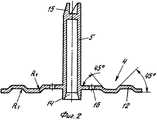
на фиг.2 - предлагаемый изобретением взбивальный диск в разрезе; иfigure 2 - proposed by the invention whipping disk in the context; and
на фиг.3 - перспективная проекция предлагаемого изобретением взбивального диска.figure 3 is a perspective projection of the invention of the whipping disk.
Осуществление изобретенияThe implementation of the invention
Описываемые далее конструктивные варианты представляют собой предпочтительные реализации предлагаемого изобретения.The structural options described below are preferred implementations of the invention.
На фиг.1 изображен чоппер в разрезе. Чоппер имеет чашу 1 и крышку 2. Крышка 2 не только служит для уплотнения чаши 1, но одновременно содержит электродвигатель 3 малой мощности вместе с механизмом привода взбивального диска 4, вращающегося на дне чаши 1. Вал 5 передает крутящий момент от приводного механизма электродвигателя 3 на взбивальный диск 4. Взбивальный диск может служить, например, для взбивания яичных белков или сливок.Figure 1 shows a chopper in section. The chopper has a bowl 1 and a cover 2. The cover 2 not only serves to seal the bowl 1, but at the same time contains a low-power electric motor 3 together with a drive mechanism for the
Опорой вала 5 в крышке 2 под приводом электродвигателя 3 служит аксиально-радиальный подшипник скольжения 6.The shaft 5 in the cover 2 under the drive of the electric motor 3 is supported by an axial radial plain bearing 6.
На нижней стороне крышки, обращенной к чаше, находится накрывающий элемент 7. Этот накрывающий элемент предназначен для плотного закрытия находящегося в чаше 1 текучего вещества: жидкости, густой массы, кубиков льда и т.п. В центре накрывающего элемента 7 имеется отверстие для прохода вала 5.On the lower side of the lid facing the bowl, there is a cover element 7. This cover element is designed to tightly close the fluid contained in the bowl 1: liquid, thick mass, ice cubes, etc. In the center of the covering element 7 there is an opening for the passage of the shaft 5.
В крышке 2 имеется, кроме того, встроенный выключатель 8 с функцией безопасности. Благодаря этому безопасному выключателю чоппер может работать, только когда крышка 2 должным образом закрывает чашу 1.The lid 2 also has a built-in switch 8 with a safety function. Thanks to this safety switch, the chopper can only work when the lid 2 properly closes the bowl 1.
На фиг.2 изображен в разрезе предлагаемый изобретением взбивальный диск. Он состоит по существу из плоского диска 4, приформованного в центре к приводному валу или стержню 5. В рассматриваемом варианте оба компонента 4 и 5 соединены между собой в единую деталь.Figure 2 shows in cross section proposed by the invention whipping disk. It consists essentially of a
Как видно из перспективной проекции на фиг.3, на диске 4 имеются концентрические возвышения 11 и углубления 10, которые с обратной стороны диска также могут рассматриваться как возвышения. Если смотреть от центра, то сначала диск 4 представляет собой плоскость. На некотором радиальном расстоянии от центра находится, если смотреть сверху, углубление 10, то есть отрицательное возвышение. За ним, в радиальном направлении, находится возвышение 11. Как углубление 10, так и возвышение 11 имеют посредине главные участки 12, расположенные практически параллельно плоскости диска. В радиальном направлении по обеим сторонам каждого главного участка 12 расположены боковые участки 13, наклоненные к плоскости диска под углом 45°. Боковые участки 13 и главные участки 12 соединяются с другими частями диска 4 и между собой с помощью закруглений одинакового диаметра, обозначенного как R1. В итоге углубление 10 и возвышение 11 приобретают в сечении синусоидальную форму. В рассматриваемом случае синусоидальный профиль взбивального диска охватывает немного больше одного полного периода синусоиды. В зависимости от вязкости приготавливаемого продукта число периодов синусоиды на диске можно варьировать. Так синусоидальный профиль радиуса диска может состоять также из 0,5, 0,75, 1,5, 2 и т.д. периодов синусоиды и промежуточных значений между ними. При взбивании сливок и мороженого хорошо зарекомендовала себя изображенная форма с одним кольцевым углублением 10 и одним концентрическим кольцевым возвышением 11.As can be seen from the perspective projection in figure 3, on the
Радиус R1 по технологическим причинам выбран одинаковым для всех изгибов диска 4. Впрочем, различные радиусы не повлияли бы принципиально на работу взбивального диска. Из гидродинамических соображений и для уменьшения риска пораниться лучше выбирать радиус R1 побольше.For technological reasons, the radius R1 was chosen the same for all the bends of the
Кроме того, вблизи центра диска 4 имеются четыре распределенных по окружности отверстия 16. Они имеют диаметр 4,5 мм. Они предназначены для того, чтобы ослабить разрежение с нижней стороны диска, возникающее вследствие того, что взбиваемое вещество при вращении диска отбрасывается в стороны. Через отверстия 16 под диск 4 может проникать новый материал, благодаря чему уменьшается осевое усилие, действующее на подшипник взбивального диска.In addition, near the center of the
Стержень 5 для привода взбивального диска 4 состоит в основном из полого вала, причем диск 4 расположен вблизи конца приводного вала 5. На этом конце находится коническая выемка 14 в приводном валу 5, которая служит для установки в ней взбивального диска (фиг.1). На противоположном конце приводного вала 5 находится сцепное устройство 15. Оно жестко сцепляется с выходной полумуфтой в крышке 2.The rod 5 for driving the
Claims (13)
Translated fromRussianApplications Claiming Priority (2)
| Application Number | Priority Date | Filing Date | Title |
|---|---|---|---|
| DE10244600.8 | 2002-09-25 | ||
| DE10244600ADE10244600A1 (en) | 2002-09-25 | 2002-09-25 | Impact disc for kitchen appliances |
Publications (2)
| Publication Number | Publication Date |
|---|---|
| RU2005107774A RU2005107774A (en) | 2006-01-20 |
| RU2336011C2true RU2336011C2 (en) | 2008-10-20 |
Family
ID=31984047
Family Applications (1)
| Application Number | Title | Priority Date | Filing Date |
|---|---|---|---|
| RU2005107774/12ARU2336011C2 (en) | 2002-09-25 | 2003-09-22 | Whipping disk for kitchen appliance |
Country Status (8)
| Country | Link |
|---|---|
| EP (1) | EP1549189B1 (en) |
| CN (1) | CN100421607C (en) |
| AT (1) | ATE322856T1 (en) |
| AU (1) | AU2003275977A1 (en) |
| DE (2) | DE10244600A1 (en) |
| ES (1) | ES2262024T3 (en) |
| RU (1) | RU2336011C2 (en) |
| WO (1) | WO2004030498A2 (en) |
Families Citing this family (9)
| Publication number | Priority date | Publication date | Assignee | Title |
|---|---|---|---|---|
| EP2314189B1 (en)* | 2009-10-22 | 2013-04-24 | Conair Corporation | Whisking disc attachment for food processor appliance |
| US9980601B2 (en)* | 2012-07-12 | 2018-05-29 | Koninklijke Philips N.V. | Device for frothing a liquid |
| US11192075B2 (en)* | 2015-06-15 | 2021-12-07 | Vita-Mix Management Corporation | Whipping blade |
| PT3310224T (en)* | 2015-06-16 | 2019-11-12 | Nestle Sa | Removal assistance food processor impeller |
| EP4588408A1 (en)* | 2015-06-16 | 2025-07-23 | Société des Produits Nestlé S.A. | Machine for homogenising a food substance |
| PT3310225T (en)* | 2015-06-16 | 2020-09-14 | Nestle Sa | Food processor with low friction impeller support |
| WO2016202817A1 (en)* | 2015-06-16 | 2016-12-22 | Nestec S.A. | Impeller for food processor |
| WO2025163177A1 (en)* | 2024-02-01 | 2025-08-07 | Seb S.A. | Work tool for a food preparation appliance |
| FR3158866A1 (en)* | 2024-02-01 | 2025-08-08 | Seb Sa | Food preparation appliance |
Citations (4)
| Publication number | Priority date | Publication date | Assignee | Title |
|---|---|---|---|---|
| GB1296909A (en)* | 1970-06-16 | 1972-11-22 | ||
| US4260272A (en)* | 1979-10-18 | 1981-04-07 | Irene E. M. Lebecque | Processor and dispenser |
| DE8811946U1 (en)* | 1988-09-21 | 1989-01-05 | Braun Ag, 6000 Frankfurt | Stirring device for preparing food |
| SU1738256A1 (en)* | 1990-05-11 | 1992-06-07 | Физико-Технический Институт Со Специальным Конструкторским Бюро И Опытным Производством Ан Ссср | Mixer |
Family Cites Families (6)
| Publication number | Priority date | Publication date | Assignee | Title |
|---|---|---|---|---|
| DE1724140U (en)* | 1956-04-10 | 1956-06-14 | Ludwig Bodemer | STIRRERS, MIXING AND STRIKING GEAR FOR HOUSEHOLD KITCHEN MACHINES. |
| JPS6033054B2 (en)* | 1981-05-29 | 1985-07-31 | 松下電器産業株式会社 | cooking machine |
| DE3425361A1 (en)* | 1983-09-24 | 1986-01-16 | Robert Krups Stiftung & Co KG, 5650 Solingen | Domestic appliance tool, in particular for kitchen machines |
| DE3334637A1 (en)* | 1983-09-24 | 1985-04-04 | Robert Krups Stiftung & Co KG, 5650 Solingen | HOUSEHOLD APPLIANCE TOOL, ESPECIALLY FOR KITCHEN MACHINES |
| DE3635086C1 (en)* | 1986-10-15 | 1988-03-31 | Braun Ag | Disc for an apparatus for the preparation of foodstuffs, in particular cream or egg white |
| CN2431817Y (en)* | 2000-08-07 | 2001-05-30 | 邱盛水 | Ceramic grinding device for vegetable or fruit |
- 2002
- 2002-09-25DEDE10244600Apatent/DE10244600A1/ennot_activeWithdrawn
- 2003
- 2003-09-22AUAU2003275977Apatent/AU2003275977A1/ennot_activeAbandoned
- 2003-09-22ATAT03798917Tpatent/ATE322856T1/ennot_activeIP Right Cessation
- 2003-09-22DEDE50302972Tpatent/DE50302972D1/ennot_activeExpired - Lifetime
- 2003-09-22ESES03798917Tpatent/ES2262024T3/ennot_activeExpired - Lifetime
- 2003-09-22WOPCT/EP2003/010531patent/WO2004030498A2/ennot_activeApplication Discontinuation
- 2003-09-22CNCNB038229226Apatent/CN100421607C/ennot_activeExpired - Fee Related
- 2003-09-22EPEP03798917Apatent/EP1549189B1/ennot_activeExpired - Lifetime
- 2003-09-22RURU2005107774/12Apatent/RU2336011C2/ennot_activeIP Right Cessation
Patent Citations (4)
| Publication number | Priority date | Publication date | Assignee | Title |
|---|---|---|---|---|
| GB1296909A (en)* | 1970-06-16 | 1972-11-22 | ||
| US4260272A (en)* | 1979-10-18 | 1981-04-07 | Irene E. M. Lebecque | Processor and dispenser |
| DE8811946U1 (en)* | 1988-09-21 | 1989-01-05 | Braun Ag, 6000 Frankfurt | Stirring device for preparing food |
| SU1738256A1 (en)* | 1990-05-11 | 1992-06-07 | Физико-Технический Институт Со Специальным Конструкторским Бюро И Опытным Производством Ан Ссср | Mixer |
Also Published As
| Publication number | Publication date |
|---|---|
| DE10244600A1 (en) | 2004-04-08 |
| ATE322856T1 (en) | 2006-04-15 |
| CN100421607C (en) | 2008-10-01 |
| WO2004030498A3 (en) | 2004-06-24 |
| CN1684617A (en) | 2005-10-19 |
| EP1549189B1 (en) | 2006-04-12 |
| ES2262024T3 (en) | 2006-11-16 |
| RU2005107774A (en) | 2006-01-20 |
| WO2004030498A2 (en) | 2004-04-15 |
| AU2003275977A1 (en) | 2004-04-23 |
| DE50302972D1 (en) | 2006-05-24 |
| AU2003275977A8 (en) | 2004-04-23 |
| EP1549189A2 (en) | 2005-07-06 |
Similar Documents
| Publication | Publication Date | Title |
|---|---|---|
| RU145448U1 (en) | MIXING CUP | |
| CN113825434A (en) | Mixing apparatus and method | |
| US7267478B2 (en) | Blender container with off center blade assembly | |
| EP3639712B1 (en) | Stirring tool | |
| EP2486833B1 (en) | Mixing vessel | |
| US20230292959A1 (en) | Handheld food blender with multiple attachments | |
| EP0795290A1 (en) | Food blender | |
| US8337072B2 (en) | Stirring tool having blades supported at radially inward edge | |
| CN113133698B (en) | Food processor with cleaning attachment and method of using the same | |
| MXPA06001472A (en) | Blender jar. | |
| JP2012531245A (en) | General purpose blades and accessories for food processors | |
| RU2336011C2 (en) | Whipping disk for kitchen appliance | |
| US12303852B2 (en) | Food processor with cleaning accessory and methods of using same | |
| US6193181B1 (en) | Electrical household appliance for cooking preparation, such as multipurpose domestic robot, and multipurpose working container | |
| US4747696A (en) | Mixing and blending apparatus | |
| EP2545832A1 (en) | Blender | |
| US20210121020A1 (en) | Food spinner attachment for electric hand blenders | |
| RU2662389C2 (en) | Tool for a kitchen appliance with a facing coating | |
| RU2332151C2 (en) | Connecting device for kitchen utensils | |
| US4648720A (en) | Beating/emulsifying tool for a domestic electrical appliance for food preparation | |
| US4669672A (en) | Food processor | |
| JPH0143152Y2 (en) | ||
| CN115135207A (en) | Food processing tool | |
| RU2332150C2 (en) | Locking device for kitchen utensils | |
| JPH10192142A (en) | Agitator with inclined shaft type cutter |
Legal Events
| Date | Code | Title | Description |
|---|---|---|---|
| PD4A | Correction of name of patent owner | ||
| MM4A | The patent is invalid due to non-payment of fees | Effective date:20190923 |