RU2335045C2 - Monolithic ceramic filter - Google Patents
Monolithic ceramic filterDownload PDFInfo
- Publication number
- RU2335045C2 RU2335045C2RU2005123579/09ARU2005123579ARU2335045C2RU 2335045 C2RU2335045 C2RU 2335045C2RU 2005123579/09 ARU2005123579/09 ARU 2005123579/09ARU 2005123579 ARU2005123579 ARU 2005123579ARU 2335045 C2RU2335045 C2RU 2335045C2
- Authority
- RU
- Russia
- Prior art keywords
- resonators
- filter
- monolithic ceramic
- elements
- input
- Prior art date
Links
- 239000000919ceramicSubstances0.000titleclaimsabstractdescription17
- 238000001465metallisationMethods0.000claimsdescription15
- 230000008878couplingEffects0.000claimsdescription6
- 238000010168coupling processMethods0.000claimsdescription6
- 238000005859coupling reactionMethods0.000claimsdescription6
- 238000004321preservationMethods0.000abstract1
- 239000000126substanceSubstances0.000abstract1
- 239000004020conductorSubstances0.000description3
- 238000004891communicationMethods0.000description2
- 239000003989dielectric materialSubstances0.000description2
- 230000007423decreaseEffects0.000description1
- 238000005516engineering processMethods0.000description1
- 230000005284excitationEffects0.000description1
- 238000009413insulationMethods0.000description1
- 230000001629suppressionEffects0.000description1
- 230000007704transitionEffects0.000description1
- 238000009966trimmingMethods0.000description1
Images

Landscapes
- Control Of Motors That Do Not Use Commutators (AREA)
Abstract
Description
Translated fromRussianИзобретение относится к технике СВЧ и предназначено для использования преимущественно в сантиметровом диапазоне волн.The invention relates to microwave technology and is intended for use mainly in the centimeter wavelength range.
Известны конструкции монолитных керамических фильтров (МКФ), состоящих из металлизированного высокодобротного керамического блока, в котором сформированы два или более резонатора, элементы входа и выхода фильтра, расположенные соосно относительно друг друга и перпендикулярно осям резонаторов, возбуждение в которых осуществляется с помощью поперечных отрезков копланарных линий. В зависимости от граничных условий на торцах этих конструкций у МКФ могут быть различные формы характеристик, но, в любом случае, это узкополосные фильтры.Known designs of monolithic ceramic filters (MKF), consisting of a metallized high-quality ceramic block, in which two or more resonators are formed, filter input and output elements located coaxially relative to each other and perpendicular to the axes of the resonators, the excitation of which is carried out using transverse segments of coplanar lines . Depending on the boundary conditions at the ends of these structures, the MKF may have various forms of characteristics, but, in any case, these are narrow-band filters.
Обычно расширение полосы пропускания МКФ осуществляют увеличением числа резонаторов в фильтре, но это приводит к увеличению габаритных размеров фильтра и увеличению потерь.Usually, the passband of an MFF is expanded by increasing the number of resonators in the filter, but this leads to an increase in the overall dimensions of the filter and an increase in losses.
Известен монолитный керамический фильтр (патент US 4879533, 7.11.1989), содержащий блок, выполненный из диэлектрического материала в виде прямоугольного параллелепипеда, на пяти из шести граней которого расположен внешний слой металлизации, имеющего между шестой гранью блока и противоположной ей гранью отверстия в количестве, соответствующем числу звеньев фильтра. Внутренний слой металлизации расположен на боковых поверхностях отверстий и присоединен к внешнему слою металлизации. На шестой грани блока над отверстиями выполнены проводящие площадки, соединенные с внутренним слоем металлизации. Проводящие площадки разделяются между собой и отделяются от внешнего слоя металлизации диэлектрическими промежутками. На шестой грани блока выполнены контактные проводники, отделенные от проводящих площадок и от внешнего слоя металлизации диэлектрическими промежутками. Несмотря на то что описанный фильтр содержит семь резонаторов, он имеет недостаточно широкую полосу пропускания, а большие габаритные размеры приводят к значительному увеличению потерь в полосе пропускания.Known monolithic ceramic filter (patent US 4879533, 7.11.1989), containing a block made of a dielectric material in the form of a rectangular parallelepiped, on five of the six faces of which there is an outer layer of metallization, having between the sixth face of the block and the opposite face of the hole in quantity, corresponding to the number of filter links. The inner metallization layer is located on the side surfaces of the holes and is attached to the outer metallization layer. On the sixth face of the block above the holes are conductive pads connected to the inner metallization layer. Conductive pads are separated and separated from the outer metallization layer by dielectric gaps. On the sixth face of the block, contact conductors are made, separated from conductive pads and from the outer metallization layer by dielectric gaps. Despite the fact that the described filter contains seven resonators, it does not have a sufficiently wide passband, and the large overall dimensions lead to a significant increase in losses in the passband.
Известен широкополосный полосно-пропускающий диэлектрический фильтр (см. UK Patent Application GB 2279182, H01P 1/205, опубл. 21.12.1994), в котором используется паз, по крайней мере, на одной грани между резонаторами. Но за счет встречно-стержневой структуры фильтра применение паза приводит к сужению полосы пропускания.Known broadband band-pass dielectric filter (see UK Patent Application GB 2279182, H01P 1/205, publ. 12/21/1994), which uses a groove on at least one face between the resonators. But due to the interdigital structure of the filter, the use of a groove leads to a narrowing of the passband.
Регулировка ширины полосы пропускания осуществляется путем частичного смещения части электрода экрана на боковой поверхности, ограничивающей разомкнутую оконечную поверхность и расположенной между смежными емкостными электродами. Ширина полосы пропускания зависит от ширины промежутка изоляции между электродами. Чем больше данный промежуток, тем шире полоса пропускания фильтра, но при расширении этого промежутка уменьшается затухание в верхней части полосы заграждения.The bandwidth is adjusted by partially offsetting a portion of the screen electrode on a side surface defining an open end surface and located between adjacent capacitive electrodes. The bandwidth depends on the width of the insulation gap between the electrodes. The larger this gap, the wider the filter bandwidth, but with the expansion of this gap, attenuation in the upper part of the boom band decreases.
Наиболее близкой к предлагаемому техническому решению является конструкция МКФ (патент RU 2248074 С1, 19.09.2003), в которой в качестве технического решения использована диэлектрическая прорезь на одной из токопроводящих площадок. Использование прорези в данной конструкции эквивалентно увеличению числа резонаторов в фильтре без увеличения габаритов фильтра. Но это техническое решение позволяет увеличить подавление сигналов на фиксированной частоте вне полосы пропускания фильтра, не решая задачу расширения полосы пропускания, фильтр остается узкополосным.Closest to the proposed technical solution is the MKF design (patent RU 2248074 C1, 09/19/2003), in which a dielectric slot on one of the conductive sites was used as a technical solution. Using a slot in this design is equivalent to increasing the number of resonators in the filter without increasing the dimensions of the filter. But this technical solution allows to increase the suppression of signals at a fixed frequency outside the passband of the filter, without solving the problem of expanding the passband, the filter remains narrow-band.
Технической задачей изобретения является расширение полосы пропускания на заданных частотах без увеличения потерь в полосе пропускания при сохранении габаритных размеров фильтра.An object of the invention is to expand the passband at given frequencies without increasing losses in the passband while maintaining the overall dimensions of the filter.
Для решения этой задачи предлагается конструкция МКФ, состоящая из металлизированного высокодобротного керамического блока в виде прямоугольного параллелепипеда с выполненными в нем отверстиями резонаторов, количество которых соответствует числу звеньев фильтра, в котором элементы входа и выхода расположены соосно относительно друг друга и перпендикулярно осям резонаторов, на пяти из шести граней которого, включая внутренние поверхности отверстий резонаторов, выполнен слой металлизации, и отличающаяся от рассматриваемых конструкций выполнением на нижней грани фильтра металлизированного паза прямоугольной формы между отверстиями резонаторов для ослабления электромагнитной связи между резонаторами и формирования нагрузки резонаторов в виде короткозамкнутых отрезков полосковых линий, длина которых определяется глубиной паза, а также реализацией на верхней грани фильтра емкостной нагрузки резонаторов в виде проводящих площадок, которые одновременно являются дополнительными элементами емкостной связи между резонаторами и подстроечными элементами.To solve this problem, an MKF design is proposed, consisting of a metallized high-quality ceramic block in the form of a rectangular parallelepiped with resonator holes made in it, the number of which corresponds to the number of filter links, in which the input and output elements are aligned with each other and perpendicular to the axes of the resonators, on five of six faces of which, including the internal surfaces of the holes of the resonators, a metallization layer is made, and which differs from the structures under consideration by performing a metallized groove of a rectangular shape on the lower face of the filter between the resonator holes to weaken the electromagnetic coupling between the resonators and forming the load of the resonators in the form of short-circuited segments of strip lines, the length of which is determined by the depth of the groove, and also implementing on the upper face of the filter a capacitive load of the resonators in the form of conductive pads , which at the same time are additional elements of capacitive coupling between resonators and tuning elements.
Предлагаемый монолитный керамический фильтр состоит из металлизированного высокодобротного керамического блока, в котором сформированы два или более резонатора. Фильтр на нижней грани имеет металлизированный паз прямоугольной формы между отверстиями резонаторов для ослабления электромагнитной связи между резонаторами и формирования нагрузки резонатора в виде короткозамкнутых отрезков полосковых линий, длину которых определяет глубина паза. На верхней грани фильтра реализована емкостная нагрузка резонаторов в виде проводящих площадок, которые одновременно являются дополнительными элементами емкостной связи между входом и выходом и подстроенными элементами. Элементы входа и выхода фильтра расположены соосно относительно друг друга и перпендикулярно осям резонаторов. В результате применения данных технических решений полоса пропускания МКФ расширяется без увеличения потерь в ней.The proposed monolithic ceramic filter consists of a metallized high-quality ceramic block in which two or more resonators are formed. The filter on the lower face has a rectangular metallized groove between the resonator holes to weaken the electromagnetic coupling between the resonators and form a resonator load in the form of short-circuited segments of strip lines, the length of which is determined by the depth of the groove. On the upper edge of the filter, a capacitive load of the resonators is implemented in the form of conductive pads, which are simultaneously additional elements of capacitive coupling between the input and output and the tuned elements. The input and output elements of the filter are located coaxially relative to each other and perpendicular to the axes of the resonators. As a result of applying these technical solutions, the IFF bandwidth is expanded without increasing losses in it.
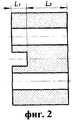
Сущность изобретения поясняется чертежами. На фиг.1 представлен МКФ, на фиг.2 разрез фильтра, при этом L1 - короткозамкнутые отрезки полосковых линий, закороченные на одном конце, определяемые глубиной паза, L2 - участок распределенной связи между резонаторами, на фиг.3 показана амплитудно-частотная характеристика фильтра с центральной частотой 5,5 ГГц. Следует отметить, что, несмотря на то что изобретение проиллюстрировано изображением монолитного керамического фильтра, имеющего два резонатора, количество резонаторов может быть увеличено. Число резонаторов ограничивается допускаемыми потерями фильтра.The invention is illustrated by drawings. Figure 1 shows the IFF, figure 2 is a section of the filter, while L1 is the short-circuited segments of strip lines shorted at one end, determined by the depth of the groove, L2 is the portion of the distributed communication between the resonators, figure 3 shows the amplitude-frequency characteristic of the filter with a center frequency of 5.5 GHz. It should be noted that, although the invention is illustrated by the image of a monolithic ceramic filter having two resonators, the number of resonators can be increased. The number of resonators is limited by the allowable filter loss.
Фильтр представляет собой монолитный керамический блок 1, выполненный из металлизированного высокодобротного диэлектрического материала в виде прямоугольного параллелепипеда, на гранях которого, кроме верхней грани 3, расположен внешний слой металлизации 2. В блоке 1 между верхней гранью 3 и гранью, противоположной ей, выполнены два отверстия 4. На боковых поверхностях отверстий 4 расположен внутренний слой металлизации 5, соединенный с внешним слоем металлизации 2. На верхней грани 3 рядом с отверстиями 4 расположены две проводящие площадки 6, соединенные с внутренним слоем металлизации 5. Проводящие площадки разделены между собой и отделены от внешнего слоя металлизации 2 диэлектрическим промежутком 7. Контактные проводники 8 размещены на торцевых гранях с переходом на боковую грань блока 1 и отделены от внешней металлизации 2 диэлектрическими промежутками 9. На нижней грани монолитного керамического блока 1 между отверстиями 4 расположен сквозной паз 10 прямоугольной формы.The filter is a monolithic ceramic block 1 made of metallized high-quality dielectric material in the form of a rectangular parallelepiped, on the faces of which, in addition to the upper face 3, there is an
Монолитный керамический фильтр работает следующим образом.Monolithic ceramic filter operates as follows.
После поступления СВЧ сигнала на контактные проводники 8 осуществляется эффективный ввод и вывод энергии в системе фильтр - линия передачи.After the microwave signal arrives at the contact conductors 8, an effective input and output of energy is carried out in the filter-transmission line system.
Фильтр формируют резонаторы, число которых определяется видом требуемой частотной характеристики. Резонаторы образованы отверстиями 4 в диэлектрическом блоке 1, внутренним слоем металлизации 5 на поверхности отверстий 4, а также проводящими площадками 6 на верхней грани 3 блока 1. Поступающий на вход фильтра сигнал через два связанных резонатора поступает на выход. При этом он проходит через два отрезка связанных симметричных линий, нагруженных с одной стороны двумя отрезками симметричных линий, закороченных на одном конце и имеющих длину, равную глубине паза.The filter is formed by resonators, the number of which is determined by the type of the required frequency response. The resonators are formed by holes 4 in the dielectric block 1, the inner metallization layer 5 on the surface of the holes 4, as well as conductive pads 6 on the upper face 3 of block 1. The signal arriving at the filter input through two connected resonators is output. Moreover, it passes through two segments of connected symmetrical lines, loaded on one side with two segments of symmetrical lines, shorted at one end and having a length equal to the depth of the groove.
Наличие сквозного паза 10 ослабляет электромагнитную связь между резонаторами и, соответственно, расширяет полосу пропускания. Размеры паза 10 определяются расчетно-экспериментальным путем и зависят от значения центральной частоты полосы пропускания. Ширина полосы пропускания дополнительно увеличивается за счет регулировки емкости связи между входом и выходом с помощью подстроечных элементов - проводящих площадок 6.The presence of a
Claims (1)
Translated fromRussianPriority Applications (1)
| Application Number | Priority Date | Filing Date | Title |
|---|---|---|---|
| RU2005123579/09ARU2335045C2 (en) | 2005-07-25 | 2005-07-25 | Monolithic ceramic filter |
Applications Claiming Priority (1)
| Application Number | Priority Date | Filing Date | Title |
|---|---|---|---|
| RU2005123579/09ARU2335045C2 (en) | 2005-07-25 | 2005-07-25 | Monolithic ceramic filter |
Publications (2)
| Publication Number | Publication Date |
|---|---|
| RU2005123579A RU2005123579A (en) | 2007-01-27 |
| RU2335045C2true RU2335045C2 (en) | 2008-09-27 |
Family
ID=37773304
Family Applications (1)
| Application Number | Title | Priority Date | Filing Date |
|---|---|---|---|
| RU2005123579/09ARU2335045C2 (en) | 2005-07-25 | 2005-07-25 | Monolithic ceramic filter |
Country Status (1)
| Country | Link |
|---|---|
| RU (1) | RU2335045C2 (en) |
Citations (5)
| Publication number | Priority date | Publication date | Assignee | Title |
|---|---|---|---|---|
| US4673902A (en)* | 1983-11-25 | 1987-06-16 | Murata Manufacturing Co., Ltd. | Dielectric material coaxial resonator filter directly mountable on a circuit board |
| US4879533A (en)* | 1988-04-01 | 1989-11-07 | Motorola, Inc. | Surface mount filter with integral transmission line connection |
| GB2279182A (en)* | 1993-06-09 | 1994-12-21 | Siemens Matsushita Components | Microwave ceramic filter |
| RU2142180C1 (en)* | 1993-09-28 | 1999-11-27 | АДС Солитра Ой | Coaxial resonator mechanical design |
| RU2248074C1 (en)* | 2003-09-19 | 2005-03-10 | Государственное образовательное учреждение высшего профессионального образования "Московский энергетический институт (технический университет)" (ГОУВПО "МЭИ (ТУ)") | Bandpass filter |
- 2005
- 2005-07-25RURU2005123579/09Apatent/RU2335045C2/ennot_activeIP Right Cessation
Patent Citations (5)
| Publication number | Priority date | Publication date | Assignee | Title |
|---|---|---|---|---|
| US4673902A (en)* | 1983-11-25 | 1987-06-16 | Murata Manufacturing Co., Ltd. | Dielectric material coaxial resonator filter directly mountable on a circuit board |
| US4879533A (en)* | 1988-04-01 | 1989-11-07 | Motorola, Inc. | Surface mount filter with integral transmission line connection |
| GB2279182A (en)* | 1993-06-09 | 1994-12-21 | Siemens Matsushita Components | Microwave ceramic filter |
| RU2142180C1 (en)* | 1993-09-28 | 1999-11-27 | АДС Солитра Ой | Coaxial resonator mechanical design |
| RU2248074C1 (en)* | 2003-09-19 | 2005-03-10 | Государственное образовательное учреждение высшего профессионального образования "Московский энергетический институт (технический университет)" (ГОУВПО "МЭИ (ТУ)") | Bandpass filter |
Also Published As
| Publication number | Publication date |
|---|---|
| RU2005123579A (en) | 2007-01-27 |
Similar Documents
| Publication | Publication Date | Title |
|---|---|---|
| JP3650957B2 (en) | Transmission line, filter, duplexer and communication device | |
| US8258897B2 (en) | Ground structures in resonators for planar and folded distributed electromagnetic wave filters | |
| NO337285B1 (en) | Bandpass Filter | |
| US9660315B2 (en) | Ground structures between resonators for distributed electromagnetic wave filters | |
| RU2362241C1 (en) | Pass-band filter | |
| KR100265694B1 (en) | Dielectric filter unit, transmitting/receiving-sharing unit, and multiplexer | |
| KR100893496B1 (en) | Broadband Filters with Suspended Substrate Structure | |
| RU2400874C1 (en) | Strip-line filter | |
| JP7360764B2 (en) | Bandpass filter and high frequency device equipped with the same | |
| RU2626224C1 (en) | Broadband stripline filter | |
| RU2335045C2 (en) | Monolithic ceramic filter | |
| US6762660B2 (en) | Compact edge coupled filter | |
| KR102259102B1 (en) | Low pass filter with transmission zero | |
| RU2675206C1 (en) | Microstrip broadband band-pass filter | |
| RU54699U1 (en) | Microwave filter | |
| RU2590313C1 (en) | Strip harmonic filter | |
| KR100858970B1 (en) | CPU low pass filter with wide stopband | |
| RU2697891C1 (en) | Microstrip diplexer | |
| KR102054503B1 (en) | Band pass filter and design method thereof | |
| JPS62278801A (en) | microstrip bandpass filter | |
| RU2807984C1 (en) | Microstrip diplexer | |
| RU2799384C1 (en) | Monolithic strip-line filter with a wide stopband | |
| KR102557957B1 (en) | Filter and multiplexer | |
| RU2248074C1 (en) | Bandpass filter | |
| RU2763482C1 (en) | Strip band-pass filter |
Legal Events
| Date | Code | Title | Description |
|---|---|---|---|
| MM4A | The patent is invalid due to non-payment of fees | Effective date:20080726 | |
| NF4A | Reinstatement of patent | Effective date:20090727 | |
| MM4A | The patent is invalid due to non-payment of fees | Effective date:20200726 |