RU2332560C1 - Well screen with cleaning function - Google Patents
Well screen with cleaning functionDownload PDFInfo
- Publication number
- RU2332560C1 RU2332560C1RU2007100432/03ARU2007100432ARU2332560C1RU 2332560 C1RU2332560 C1RU 2332560C1RU 2007100432/03 ARU2007100432/03 ARU 2007100432/03ARU 2007100432 ARU2007100432 ARU 2007100432ARU 2332560 C1RU2332560 C1RU 2332560C1
- Authority
- RU
- Russia
- Prior art keywords
- pipe
- filter
- filter element
- well
- cleaning function
- Prior art date
Links
Images


Landscapes
- Filtration Of Liquid (AREA)
Abstract
Description
Translated fromRussianИзобретение относится к горной промышленности, а именно к нефтегазодобывающей, и может быть использовано при освоении нефтяных и газовых скважин для очистки добываемого продукта от песка. При этом в скважинном фильтре предусмотрена система очистки от асфальтосмолистых и парафиногидратных отложений.The invention relates to the mining industry, namely, oil and gas, and can be used in the development of oil and gas wells for cleaning the produced product from sand. At the same time, the downhole filter provides a system for cleaning from asphalt-tar and paraffin hydrate deposits.
Известен скважинный фильтр по А.С. СССР №1788219, содержащий перфорированную трубу и съемные металлокерамические элементы, установленные с наружной стороны трубы. Недостаток такого фильтра - это необходимость периодической замены фильтрующих элементов и низкая прочность при изгибающих нагрузках.Well-known filter according to A.S. USSR No. 1788219, containing a perforated pipe and removable cermet elements mounted on the outside of the pipe. The disadvantage of this filter is the need for periodic replacement of filter elements and low strength under bending loads.
Известен скважинный фильтр по А.С. СССР №1754884, содержащий фильтрующий элемент в виде дуговых пластин, с фильтрующими щелями. Кроме недостатков, присущих выше описанному фильтру, этот фильтр сложен в сборке, т.к. содержит большое количество мелких деталей, выполненных с высокой точностью.Well-known filter according to A.S. USSR No. 1754884, containing a filter element in the form of arc plates, with filter slots. In addition to the disadvantages inherent in the above described filter, this filter is difficult to assemble, because contains a large number of small parts made with high accuracy.
Известен скважинный фильтр по А.С. СССР №1645470, содержащий уложенный на перфорированный каркас проволочный фильтрующий элемент. Этот фильтр плохо работает при изгибающих нагрузках: с одной стороны, проходное сечение щелей при изгибе уменьшается, а с другой - увеличивается и фильтр пропускает более крупные фракции примесей. При этом увеличивается износ оборудования, перекачивающего нефть.Well-known filter according to A.S. USSR No. 1645470, containing a wire filter element laid on a perforated frame. This filter does not work well under bending loads: on the one hand, the bore of the slots decreases when bending, and on the other hand, it increases and the filter passes larger impurity fractions. This increases the wear of equipment pumping oil.
Известен скважинный фильтр по патенту РФ №2108447, содержащий трубу с герметичными срезаемыми пробками. Колонну обсадных труб с фильтром опускают в скважину. Скважину цементируют выше фильтра. После схватывания цементного раствора в скважину спускают колонну насосно-компрессорных труб с воронкой. Скважину промывают. Срезают воронкой концы пробок. Скважину промывают вторично. Разгерметизируют продуктивный пласт и одновременно с этим пускают скважину в работу.Known downhole filter according to the patent of the Russian Federation No. 2108447, containing a pipe with sealed shear plugs. The casing string with the filter is lowered into the well. The well is cemented above the filter. After setting the cement slurry, a tubing string with a funnel is lowered into the well. The well is washed. Cut off the ends of the plugs with a funnel. The well is washed a second time. Depressurize the reservoir and at the same time put the well into operation.
Недостаток - уменьшение дебита скважины в процессе ее эксплуатации за счет отложения на фильтрующих элементах асфальтосмолистых и парафиногидратных отложений.The disadvantage is the reduction in the flow rate of the well during its operation due to the deposition of asphalt-resinous and paraffin hydrate deposits on the filtering elements.
Известны скважинный фильтр и система его очистки от отложений по патенту РФ №2148152. Очистка фильтра выполняется прокачкой раствора кислоты через фильтрующие элементы, это приводит к коррозии труб, фильтрующих сеток и защитного кожуха фильтра, а асфальтосмолистые и парафиногидратные отложения в кислотах не растворяются.Known downhole filter and a system for cleaning it from deposits according to the patent of the Russian Federation No. 2148152. The filter is cleaned by pumping the acid solution through the filter elements, this leads to corrosion of the pipes, filter nets and the filter protective cover, and asphalt-resinous and paraffin hydrate deposits do not dissolve in acids.
Известно устройство для очистки скважинного фильтра по патенту РФ №2112867, прототип.A device for cleaning the downhole filter according to the patent of the Russian Federation No. 2112867, prototype.
Устройство для очистки скважинного фильтра включает корпус, на поверхности которого размещены эластичные элементы, в отличие от прототипа устройство снабжено цилиндрической резьбовой втулкой и ступенчатой втулкой, на цилиндрической поверхности меньшего диаметра которой выполнена резьба, корпус со стороны верхнего торца снабжен резьбовым хвостовиком, взаимодействующим с цилиндрической резьбовой втулкой, и со стороны нижнего торца в корпусе выполнено по оси резьбовое отверстие, взаимодействующее с цилиндрической резьбовой поверхностью ступенчатой втулки, эластичные элементы размещены между цилиндрической резьбовой втулкой и корпусом сверху и между корпусом и ступенчатой втулкой снизу, на боковой поверхности корпуса между эластичными элементами выполнены промывочные отверстия, а на нижнем торце ступенчатой втулки расположен узел расфиксации, выполненный с возможностью взаимодействия со стопорным пазом, выполненным в фильтре.A device for cleaning a downhole filter includes a housing, on the surface of which elastic elements are placed, in contrast to the prototype, the device is equipped with a cylindrical threaded sleeve and a stepped sleeve, a thread is made on the cylindrical surface of a smaller diameter, the housing on the upper end side is equipped with a threaded shank interacting with a cylindrical threaded bushing, and from the side of the lower end in the housing, a threaded hole is made along the axis, interacting with a cylindrical threaded surface of the stepped sleeve, elastic elements are placed between the cylindrical threaded sleeve and the body on top and between the body and the stepped sleeve from below, on the side surface of the body between the elastic elements there are washing holes, and on the lower end of the stepped sleeve there is a release unit configured to interact with the locking groove made in the filter.
Недостатки способа и устройства: большие экономические затраты на проведение очистки, связанные с необходимостью установить приспособление для очистки на большой глубине.The disadvantages of the method and device: high economic costs of cleaning, associated with the need to install the device for cleaning at great depths.
Недостатки этого способа очистки фильтра и устройства для его реализации: недостаточная эффективность очистки от асфальтосмолистых и парафиногидратных отложений.The disadvantages of this method of cleaning the filter and device for its implementation: the lack of effectiveness in cleaning from asphalt-tar and paraffin deposits.
Задача создания изобретения: увеличение дебита скважины за счет периодической очистки фильтрующих сеток.The task of creating the invention: increasing the flow rate of the well due to the periodic cleaning of the filter mesh.
Решение указанной задачи достигнуто тем, что скважинный фильтр с функцией очистки, выполненный в виде трубы с ниппельными резьбовыми участками, на одном из которых установлена соединительная муфта, и с отверстиями на боковой поверхности трубы, концентрично которой установлен фильтрующий элемент, отличается тем, что фильтрующий элемент выполнен в виде двух изолированных друг от друга электродов, установленных концентрично на трубе и имеющих возможность подключения к источнику электроэнергии. Один из электродов может быть выполнен в виде металлической сетки, а функцию другого выполняет труба. Оба электрода могут быть выполнены в виде металлической сетки, электрически изолированными друг от друга. Функции изолятора выполняют сетки из неэлектропроводного материала. Металлическая сетка может быть закрыта защитным кожухом. Между металлической сеткой и защитным кожухом установлена дренажная сетка. Скважинный фильтр может быть оборудован быстроразъемным электрическим соединителем для соединения при помощи кабеля с источником электроэнергии, размещенным на поверхности, или автономным источником энергии, например, батареей элементов питания или электрогенератором, установленным внутри скважинного фильтра. На торцах трубы установлены контактные кольца, электрически изолированные от корпуса трубы. Соединение контактных колец с металлической сеткой выполнено проводом, уложенным в продольной канавке, выполненной в трубе, заполненной электроизоляционным материалом. Перед ниппелем в продольной канавке выполнено отверстие, через которое пропущен провод, соединяющий контактное кольцо на торце трубы с металлической сеткой.The solution to this problem was achieved in that a well filter with a cleaning function, made in the form of a pipe with nipple threaded sections, one of which has a coupling, and with holes on the side surface of the pipe concentrically mounted with a filter element, is characterized in that the filter element made in the form of two electrodes isolated from each other, mounted concentrically on the pipe and having the ability to connect to a source of electricity. One of the electrodes can be made in the form of a metal mesh, and the pipe performs the function of the other. Both electrodes can be made in the form of a metal grid, electrically isolated from each other. The functions of the insulator are performed by grids of non-conductive material. The metal mesh can be covered with a protective cover. A drainage net is installed between the metal mesh and the protective cover. The downhole filter can be equipped with a quick-disconnect electrical connector for connecting with a cable to a power source located on the surface, or an autonomous energy source, for example, a battery of batteries or an electric generator installed inside the downhole filter. At the ends of the pipe there are contact rings electrically isolated from the pipe body. The connection of the slip rings with a metal mesh is made by a wire laid in a longitudinal groove made in a pipe filled with electrical insulating material. A hole is made in front of the nipple in the longitudinal groove, through which a wire is passed connecting the contact ring at the pipe end with a metal mesh.
Исследования патентной и научно-технической литературы показали, что подобная совокупность существенных признаков является новой и ранее не использовалась, что в свою очередь позволяет сделать заключение о соответствии технического решения критерию «новизна» и изобретательский уровень. Наличие этих критериев подтверждается патентными исследованиями. Предложенное техническое решение также обладает критерием «промышленная применимость», т.к. фильтр может быть изготовлен с помощью стандартного оборудования из недифицитных материалов.Studies of patent and scientific and technical literature have shown that such a combination of essential features is new and has not been used before, which in turn allows us to conclude that the technical solution meets the criterion of "novelty" and inventive step. The presence of these criteria is confirmed by patent research. The proposed technical solution also has the criterion of "industrial applicability", because the filter can be made using standard equipment from non-essential materials.
Сущность изобретения поясняется чертежами, где:The invention is illustrated by drawings, where:
на фиг.1 приведена конструкция фильтрующего устройства, содержащего фильтры одинаковой конструкции,figure 1 shows the design of a filtering device containing filters of the same design,
на фиг.2 - вид А одного из вариантов фильтрующего элемента,figure 2 is a view And one of the options for the filter element,
на фиг.3 - вид А второго варианта фильтрующего элемента,figure 3 is a view And the second variant of the filter element,
на фиг.4 - вид Б-Бfigure 4 is a view of BB
на фиг.5 - вид В-В,figure 5 is a view of BB
на фиг.6 - вид Г до сборки,Fig.6 is a view of G to the assembly,
на фиг.7 - вид Г после сборки.Fig.7 is a view of G after assembly.
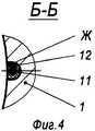
Фильтрующее устройство (фиг.1) для нефтяных скважин состоит не менее чем из одного фильтра, соединенного с колонной обсадных труб. Каждый фильтр состоит из трубы 1 с ниппельными резьбовыми участками 2 на концах, на одном из ниппельных резьбовых участков 2 установлена муфта 3. На трубе 1 выполнены отверстия «Д» и установлен фильтрующий элемент 4. В качестве фильтрующего элемента 4 могут быть использованы один или несколько рядов металлической сетки или проволоки. Предпочтительно в качестве фильтрующего элемента 4 применить (фиг.2) металлическую сетку 5, изолированную с двух сторон диэлектрическими прокладками 6, и дренажную сетку 7 (фиг.3). Фильтрующий элемент 4 может содержать защитный кожух 8. На защитном кожухе 8 выполнены отверстия «Н». С торцов сеток 5 и 7 установлены кольца из неэлектропроводного материала 9.The filtering device (figure 1) for oil wells consists of at least one filter connected to the casing string. Each filter consists of a
В верхнем и нижнем ниппеле 2 установлены контактные кольца 10 и 13, соединенные с электрически изолированной сеткой и между собой.In the upper and
На трубе 1 выполнены продольные канавки «Ж», в которых проложены электрические провода 11, залитые электроизоляционным материалом (компаундом) 12, изолированные от корпуса муфты 3.On the
На трубе 1 (фиг.4) установлены упругие контактные кольца 13, которые изолированы от металлических частей неэлектроводными втулками 14. Соединение упругих контактных колец 13 с основной металлической сеткой 5 выполнено проводом 11, уложенным в продольной канавке «И», выполненной на трубе 1, заполненной электроизоляционным материалом 12. Перед ниппелем 3 в продольной канавке «И» выполнено отверстие «К», через которое пропущен провод 11, соединяющий упругое контактное кольцо 13 на торце трубы 1 с основной металлической сеткой 5.On the pipe 1 (figure 4) installed
При сборке обсадной колонны (фиг.6 и 7) ниппель 2 верхнего фильтра 15 соединяют с нижним фильтром через муфту 3, для этого свинчивают ниппельный резьбовой участок 15 с муфтой 3. При этом упругий контакт 13 соединяется с контактом 10, соединяя электрическую цепь фильтров, вошедших в компоновку. Источники питания на фиг.1...7 не показаны. Фильтры соединяют последовательно в зависимости от протяженности нефтяного пласта.When assembling the casing (FIGS. 6 and 7), the
Компоновку колонны обсадных труб опускают в скважину, скважину цементируют выше фильтров. Скважина готова к работе. Нефть, газ или вода поступает одновременно к фильтрующим элементам 4 всех фильтров. В процессе эксплуатации ячейки в сетках 5 и 7 забиваются асфальтосмолистыми и парафиногидратными отложениями.The casing string is lowered into the well, the well is cemented above the filters. The well is ready to go. Oil, gas or water flows simultaneously to the filter elements 4 of all filters. During operation, the cells in meshes 5 and 7 are clogged with asphalt-resinous and paraffin-hydrate deposits.
Для отчистки от отложений в обсадную колонну опускают кабель. Кабель соединяется с контактом 16, вторым контактом является масса. Электроэнергию подводят по кабелю к сеткам 5 и 7. В зазоре между сетками 5 и 7 нефть, содержащая воду, соли и газ, разогревается до температуры выше температуры плавления парафина. Асфальтосмолистые и парафиногидратные отложения расплавляются и стекают вниз. Фильтр очищается, кабель поднимают и скважину вновь вводят в эксплуатацию.To clear deposits from the casing, lower the cable. The cable connects to pin 16, the second pin is ground. Electricity is supplied by cable to the grids 5 and 7. In the gap between the grids 5 and 7, oil containing water, salts and gas is heated to a temperature above the melting point of paraffin. Asphalt-resinous and paraffin hydrate deposits melt and flow down. The filter is cleaned, the cable is lifted and the well is put back into operation.
Возможно применение автономного источника питания, например, батареи элементов питания или заранее установленного внутри фильтра генератора (на фиг.1...7 не показано).It is possible to use an autonomous power source, for example, a battery of batteries or a generator pre-installed inside the filter (not shown in FIGS. 1 ... 7).
Применение изобретения позволило:The application of the invention allowed:
1. Поддерживать рабочие дебиты скважины на требуемом уровне без извлечения фильтра для его очистки за счет полной очистки фильтрующего элемента скважинного фильтра.1. To maintain the working flow rate of the well at the required level without removing the filter to clean it by completely cleaning the filter element of the well filter.
2. Повысить нефтеотдачу скважин.2. To increase oil recovery wells.
3. Снизить стоимость операции очистки фильтра по сравнению с известными фильтрами.3. Reduce the cost of filter cleaning operations in comparison with known filters.
4. Увеличить степень очистки продукта (нефти) от примесей.4. To increase the degree of purification of the product (oil) from impurities.
5. Обеспечить эксплуатацию скважинных фильтров в течение всего срока эксплуатации скважины.5. Ensure the operation of well filters throughout the life of the well.
6. Предотвратить разрушение и коррозию фильтрующего элемента.6. To prevent destruction and corrosion of the filter element.
7. Упростить сборку скважинного фильтра.7. To simplify the assembly of the downhole filter.
Claims (2)
Translated fromRussianPriority Applications (1)
| Application Number | Priority Date | Filing Date | Title |
|---|---|---|---|
| RU2007100432/03ARU2332560C1 (en) | 2007-01-09 | 2007-01-09 | Well screen with cleaning function |
Applications Claiming Priority (1)
| Application Number | Priority Date | Filing Date | Title |
|---|---|---|---|
| RU2007100432/03ARU2332560C1 (en) | 2007-01-09 | 2007-01-09 | Well screen with cleaning function |
Publications (1)
| Publication Number | Publication Date |
|---|---|
| RU2332560C1true RU2332560C1 (en) | 2008-08-27 |
Family
ID=46274560
Family Applications (1)
| Application Number | Title | Priority Date | Filing Date |
|---|---|---|---|
| RU2007100432/03ARU2332560C1 (en) | 2007-01-09 | 2007-01-09 | Well screen with cleaning function |
Country Status (1)
| Country | Link |
|---|---|
| RU (1) | RU2332560C1 (en) |
Citations (11)
| Publication number | Priority date | Publication date | Assignee | Title |
|---|---|---|---|---|
| SU414005A1 (en)* | 1972-01-03 | 1974-02-05 | ||
| SU558689A1 (en)* | 1973-12-10 | 1977-05-25 | Separator | |
| SU685632A1 (en)* | 1978-03-27 | 1979-09-15 | Всесоюзный Научно-Исследовательский И Проектно-Конструкторский Институт По Осушению Месторождений Полезных Ископаемых, Специальным Горным Работам Рудничной Геологии И Маркшейдерскому Делу | Filter |
| SU927919A1 (en)* | 1980-09-11 | 1982-05-15 | Ивано-Франковский Институт Нефти И Газа | Device for cleaning the filters of operating water wells |
| SU1164377A1 (en)* | 1983-11-21 | 1985-06-30 | Всесоюзный Научно-Исследовательский Институт Водоснабжения,Канализации,Гидротехнических Сооружений И Инженерной Гидрогеологии | Deep-well three-electrode heater |
| SU1609698A1 (en)* | 1988-06-23 | 1990-11-30 | Научно-исследовательский, проектно-конструкторский и технологический кабельный институт | Extruder filter |
| RU2050331C1 (en)* | 1994-06-21 | 1995-12-20 | Халуша Григорий Аронович | Liquid mediums treatment apparatus |
| RU2055801C1 (en)* | 1991-07-08 | 1996-03-10 | Кемеровский технологический институт пищевой промышленности | Device for warming up viscous materials in container |
| GB2380750A (en)* | 2000-05-18 | 2003-04-16 | Halliburton Energy Serv Inc | Thin-wall expandable well screen assembly and associated fabrication methods |
| RU2203366C2 (en)* | 2001-08-01 | 2003-04-27 | Тельных Виктор Анатольевич | Well screen |
| RU38833U1 (en)* | 2004-03-10 | 2004-07-10 | ОАО "Поволжский НИИ материалов и технологий авиационных двигателей" | Borehole Filter |
- 2007
- 2007-01-09RURU2007100432/03Apatent/RU2332560C1/enactive
Patent Citations (11)
| Publication number | Priority date | Publication date | Assignee | Title |
|---|---|---|---|---|
| SU414005A1 (en)* | 1972-01-03 | 1974-02-05 | ||
| SU558689A1 (en)* | 1973-12-10 | 1977-05-25 | Separator | |
| SU685632A1 (en)* | 1978-03-27 | 1979-09-15 | Всесоюзный Научно-Исследовательский И Проектно-Конструкторский Институт По Осушению Месторождений Полезных Ископаемых, Специальным Горным Работам Рудничной Геологии И Маркшейдерскому Делу | Filter |
| SU927919A1 (en)* | 1980-09-11 | 1982-05-15 | Ивано-Франковский Институт Нефти И Газа | Device for cleaning the filters of operating water wells |
| SU1164377A1 (en)* | 1983-11-21 | 1985-06-30 | Всесоюзный Научно-Исследовательский Институт Водоснабжения,Канализации,Гидротехнических Сооружений И Инженерной Гидрогеологии | Deep-well three-electrode heater |
| SU1609698A1 (en)* | 1988-06-23 | 1990-11-30 | Научно-исследовательский, проектно-конструкторский и технологический кабельный институт | Extruder filter |
| RU2055801C1 (en)* | 1991-07-08 | 1996-03-10 | Кемеровский технологический институт пищевой промышленности | Device for warming up viscous materials in container |
| RU2050331C1 (en)* | 1994-06-21 | 1995-12-20 | Халуша Григорий Аронович | Liquid mediums treatment apparatus |
| GB2380750A (en)* | 2000-05-18 | 2003-04-16 | Halliburton Energy Serv Inc | Thin-wall expandable well screen assembly and associated fabrication methods |
| RU2203366C2 (en)* | 2001-08-01 | 2003-04-27 | Тельных Виктор Анатольевич | Well screen |
| RU38833U1 (en)* | 2004-03-10 | 2004-07-10 | ОАО "Поволжский НИИ материалов и технологий авиационных двигателей" | Borehole Filter |
Similar Documents
| Publication | Publication Date | Title |
|---|---|---|
| US4400259A (en) | Deep anode assembly | |
| RU2338871C1 (en) | Self-cleaning well strainer | |
| KR100928719B1 (en) | Construction method of high strength ground rod for boring ground | |
| RU2332560C1 (en) | Well screen with cleaning function | |
| RU157109U1 (en) | ELECTROLYTIC EARTHING DEVICE | |
| KR101477460B1 (en) | Grounding apparatus | |
| RU2010119361A (en) | SYSTEM, METHOD AND DEVICE FOR CREATING A Glow ELECTRIC DISCHARGE | |
| RU2471987C1 (en) | Electric pulse drilling bit | |
| CN220226820U (en) | Downhole electric heating paraffin removal tool | |
| RU2347892C2 (en) | Well filter to prevent asphalt/tar and paraffin/hydrate deposits | |
| KR101084483B1 (en) | Mesh ground structure | |
| RU2259472C2 (en) | Well filter | |
| RU2132452C1 (en) | Method and device for liquidation of paraffin-crystallohydrate plug in wells | |
| RU2204696C1 (en) | Bottom-hole water heater for injection well | |
| RU2500873C1 (en) | Electric pulse drilling assembly | |
| RU2444613C1 (en) | Protective device of well electric centrifugal pump installation under complicated conditions | |
| RU2231575C1 (en) | Device for cathodic protection of a well pump and an electric cable for power feeding to an electric motor of the protected well pump | |
| RU60131U1 (en) | Borehole Filter (OPTIONS) | |
| KR20100112510A (en) | High strength ground rod for boring ground and its construction method | |
| CN205654323U (en) | Producing string wax scraping device | |
| RU133980U1 (en) | ELECTROLYTIC EARTHING DEVICE | |
| RU2345213C1 (en) | Method for making well screen | |
| CN116498267B (en) | Underground electric heating wax removal tools | |
| RU2601031C1 (en) | Method for recovery of deep anode bed | |
| JP5705801B2 (en) | Well closure device and method for closing it |