RU2329910C2 - Folding structural system - Google Patents
Folding structural systemDownload PDFInfo
- Publication number
- RU2329910C2 RU2329910C2RU2005126045/11ARU2005126045ARU2329910C2RU 2329910 C2RU2329910 C2RU 2329910C2RU 2005126045/11 ARU2005126045/11 ARU 2005126045/11ARU 2005126045 ARU2005126045 ARU 2005126045ARU 2329910 C2RU2329910 C2RU 2329910C2
- Authority
- RU
- Russia
- Prior art keywords
- connection
- triangle
- folding
- axis
- deployment
- Prior art date
Links
- 238000010276constructionMethods0.000claimsdescription8
- 239000000126substanceSubstances0.000abstract1
- 208000002740Muscle RigidityDiseases0.000description8
- 230000008878couplingEffects0.000description5
- 238000010168coupling processMethods0.000description5
- 238000005859coupling reactionMethods0.000description5
- 230000002093peripheral effectEffects0.000description4
- 206010052904Musculoskeletal stiffnessDiseases0.000description2
- 210000001364upper extremityAnatomy0.000description2
- 239000011248coating agentSubstances0.000description1
- 238000000576coating methodMethods0.000description1
- 230000007423decreaseEffects0.000description1
- 230000002349favourable effectEffects0.000description1
- 239000000463materialSubstances0.000description1
- 239000011253protective coatingSubstances0.000description1
- 238000000926separation methodMethods0.000description1
- 239000007787solidSubstances0.000description1
Images


Classifications
- B—PERFORMING OPERATIONS; TRANSPORTING
- B62—LAND VEHICLES FOR TRAVELLING OTHERWISE THAN ON RAILS
- B62B—HAND-PROPELLED VEHICLES, e.g. HAND CARTS OR PERAMBULATORS; SLEDGES
- B62B7/00—Carriages for children; Perambulators, e.g. dolls' perambulators
- B62B7/04—Carriages for children; Perambulators, e.g. dolls' perambulators having more than one wheel axis; Steering devices therefor
- B62B7/06—Carriages for children; Perambulators, e.g. dolls' perambulators having more than one wheel axis; Steering devices therefor collapsible or foldable
- B62B7/08—Carriages for children; Perambulators, e.g. dolls' perambulators having more than one wheel axis; Steering devices therefor collapsible or foldable in the direction of, or at right angles to, the wheel axis
- B—PERFORMING OPERATIONS; TRANSPORTING
- B62—LAND VEHICLES FOR TRAVELLING OTHERWISE THAN ON RAILS
- B62B—HAND-PROPELLED VEHICLES, e.g. HAND CARTS OR PERAMBULATORS; SLEDGES
- B62B7/00—Carriages for children; Perambulators, e.g. dolls' perambulators
- B62B7/04—Carriages for children; Perambulators, e.g. dolls' perambulators having more than one wheel axis; Steering devices therefor
- B62B7/06—Carriages for children; Perambulators, e.g. dolls' perambulators having more than one wheel axis; Steering devices therefor collapsible or foldable
- B62B7/068—Carriages for children; Perambulators, e.g. dolls' perambulators having more than one wheel axis; Steering devices therefor collapsible or foldable by sliding a bushing along a rod, e.g. like folding means of an umbrella
- B—PERFORMING OPERATIONS; TRANSPORTING
- B62—LAND VEHICLES FOR TRAVELLING OTHERWISE THAN ON RAILS
- B62B—HAND-PROPELLED VEHICLES, e.g. HAND CARTS OR PERAMBULATORS; SLEDGES
- B62B9/00—Accessories or details specially adapted for children's carriages or perambulators
- B62B9/10—Perambulator bodies; Equipment therefor
- B62B9/12—Perambulator bodies; Equipment therefor involving parts that are adjustable, attachable or detachable
- B—PERFORMING OPERATIONS; TRANSPORTING
- B62—LAND VEHICLES FOR TRAVELLING OTHERWISE THAN ON RAILS
- B62B—HAND-PROPELLED VEHICLES, e.g. HAND CARTS OR PERAMBULATORS; SLEDGES
- B62B5/00—Accessories or details specially adapted for hand carts
- B62B5/06—Hand moving equipment, e.g. handle bars
- B62B5/067—Stowable or retractable handle bars
Landscapes
- Engineering & Computer Science (AREA)
- Chemical & Material Sciences (AREA)
- Combustion & Propulsion (AREA)
- Transportation (AREA)
- Mechanical Engineering (AREA)
- Health & Medical Sciences (AREA)
- Public Health (AREA)
- Carriages For Children, Sleds, And Other Hand-Operated Vehicles (AREA)
- Toys (AREA)
- Tents Or Canopies (AREA)
Abstract
Description
Translated fromRussianЭто изобретение относится к складной конструкции, которая включает в себя детскую складную прогулочную коляску, но не ограничивается ею, и которая содержит:This invention relates to a folding structure, which includes, but is not limited to, a folding baby stroller, and which includes:
стойку;a rack;
блок скольжения, скользящий на стойке по оси, при этом блок скольжения блокирован от вращения вокруг этой оси;a sliding block sliding along the axis on the strut, while the sliding block is blocked from rotation around this axis;
по меньшей мере, одну складную ножку, раскладываемую из сложенного положения вблизи стойки в разложенное положение на расстоянии от стойки;at least one folding leg, folding from a folded position near the rack to the unfolded position at a distance from the rack;
сочлененную конструкцию для раскладывания ножки, содержащую, если смотреть по направлению, отличающемуся от упомянутой оси, сочлененный треугольник развертывания;an articulated structure for unfolding the legs, comprising, when viewed in a direction different from said axis, an articulated deployment triangle;
при этом треугольник развертывания содержит:wherein the deployment triangle contains:
первую сторону, прикрепленную к стойке между первым соединением, расположенным на стойке, и вторым соединением, расположенным в точке блока скольжения;a first side attached to the strut between the first joint located on the strut and the second joint located at a point of the sliding block;
вторую сторону, присоединенную к блоку скольжения посредством второго соединения;a second side attached to the sliding unit by means of a second connection;
третью сторону, подсоединенную к стойке посредством первого соединения и ко второй стороне посредством третьего соединения.a third side connected to the rack through the first connection and to the second side through the third connection.
Такая конструкция известна из патента Франции №2259001. Конструкция этого типа обеспечивает возможность относительно простого раскладывания такой складной конструкции, как детская складная прогулочная коляска. По существу, раскладывание ножек детской складной прогулочной коляски будет обеспечено прямолинейным движением блока скольжения вдоль стойки. Такой тип складывания, подобный складыванию зонтика, позволяет избежать неудобств, известных в отношении находящихся в обращении, так называемых тележек с «зонтичным складыванием», в которых должно быть выполнено большое количество операций раскладывания, чтобы получить разложенное положение конструкции.Such a construction is known from French Patent No. 225,951. This type of construction makes it possible to relatively easily unfold a folding structure such as a folding baby stroller. Essentially, the unfolding of the legs of the folding baby stroller will be ensured by the rectilinear movement of the sliding block along the rack. This type of folding, similar to folding an umbrella, avoids the inconvenience known with respect to the so-called "umbrella folding" trolleys, in which a large number of folding operations have to be performed in order to obtain an unfolded position of the structure.
Однако сиденья вышеупомянутого типа не вполне удовлетворительны. Фактически вторую и третью сочлененные стороны треугольника развертывания для таких сидений конструируют из простых соединительных стержней. Эти соединительные стержни соответствующим образом связаны с блоком скольжения и со стойкой с помощью простых шарниров. Следовательно, жесткость конструкции в разложенном положении будет обеспечена этой группой соединительных стержней и шарниров. Таким образом, если эти шарниры не обладают жесткостью, то треугольник развертывания и, следовательно, связанная с ним ножка будут обладать недостаточной периферийной жесткостью по отношению к стойке. В этом случае необходимо использовать для шарниров сложное средство повышения жесткости, например моноблочную конструкцию, обеспеченную опорами в форме каналов, выполненную за одно целое с блоком скольжения.However, the seats of the aforementioned type are not entirely satisfactory. In fact, the second and third articulated sides of the deployment triangle for such seats are constructed from simple connecting rods. These connecting rods are appropriately connected to the sliding block and the strut using simple hinges. Therefore, the rigidity of the structure in the unfolded position will be provided by this group of connecting rods and hinges. Thus, if these hinges do not have rigidity, then the deployment triangle and, therefore, the leg connected with it will have insufficient peripheral rigidity with respect to the strut. In this case, it is necessary to use for hinges a complex means of increasing rigidity, for example, a monoblock design provided with supports in the form of channels, made in one piece with the sliding block.
Известный уровень техники также включает в себя патент Франции №2167594, в котором раскрыта складная конструкция, не имеющая жесткого направляющего треугольника. Лишь предполагаемый направляющий треугольник проходит от трех точек, соответствующим образом связывая (i) точку, расположенную в самом нижнем конце L-образной основной опоры (определяющую ось линейного раскладывания детской складной прогулочной коляски), (ii) точку на горизонтальной части L-образной основной опоры и, наконец, (iii) точку на опоре для одного из задних колесиков. В этой конструкции гарантировано, что один из участков, образующих треугольник, выполнен нежестким или гибким, поскольку одна из точек, образующих вершины треугольника, не находится на оси вращения участка треугольника, противоположного этой точке. Как показано на фиг.3, такая гибкость может быть обеспечена посредством дополнительного линейного шарнира вблизи от шарового шарнира в углу. Таким образом, этот направляющий треугольник никак не образует жесткую конструкцию.The prior art also includes French patent No. 2167594, which discloses a folding structure that does not have a rigid guide triangle. Only the alleged guide triangle extends from three points, appropriately linking (i) the point located at the lowest end of the L-shaped main support (defining the linear axis of the folding baby stroller), (ii) the point on the horizontal part of the L-shaped main support and finally (iii) a fulcrum for one of the rear wheels. In this design, it is guaranteed that one of the sections forming the triangle is non-rigid or flexible, since one of the points forming the vertices of the triangle is not located on the axis of rotation of the triangle section opposite to this point. As shown in FIG. 3, such flexibility can be provided by an additional linear hinge close to the ball joint in the corner. Thus, this guide triangle does not form a rigid structure.
Основная цель изобретения заключается в решении этой проблемы посредством создания легко складываемой конструкции, которой будет придана жесткость в разложенном положении с помощью недорогих и легких средств.The main objective of the invention is to solve this problem by creating an easily foldable structure, which will be given rigidity in the unfolded position using inexpensive and lightweight means.
С этой целью изобретение относится к складной конструкции вышеупомянутого типа, в которой первое соединение или второе соединение содержит две отстоящих точки соединения по упомянутому направлению, так что сторона треугольника развертывания, которая присоединена в этих точках, составляет жесткий направляющий треугольник, определяемый этими двумя точками и третьим соединением.To this end, the invention relates to a folding structure of the aforementioned type, in which the first connection or the second connection contains two spaced connection points in the aforementioned direction, so that the side of the deployment triangle that is attached at these points constitutes a rigid guide triangle defined by these two points and the third connection.
Конструкция согласно изобретению может иметь одну или более из следующих характеристик, причем как в отдельности, так и во всех возможных технических сочетаниях:The design according to the invention may have one or more of the following characteristics, both individually and in all possible technical combinations:
жесткий направляющий треугольник содержит три боковых элемента, при этом один из боковых элементов совпадает с шарнирной осью, а два других боковых элемента закреплены по отношению друг к другу;a rigid guide triangle contains three side elements, while one of the side elements coincides with the hinge axis, and the other two side elements are fixed relative to each other;
поверхность, ограниченная вершинами направляющего треугольника, представляет собой сплошную поверхность, например пластину;the surface bounded by the vertices of the guide triangle is a continuous surface, such as a plate;
поверхность, ограниченная вершинами направляющего треугольника, представляет собой поверхность с вырезом;the surface bounded by the vertices of the guide triangle is a cut-out surface;
ножка выполнена за одно целое со второй стороной треугольника развертывания;the leg is made in one piece with the second side of the deployment triangle;
ножка присоединена к третьей стороне треугольника развертывания или на продолжении этой стороны, а опорная часть присоединена между (i) блоком скольжения и (ii) промежуточной точкой на ножке;the leg is attached to the third side of the deployment triangle or on the extension of this side, and the supporting part is connected between (i) the sliding block and (ii) the intermediate point on the leg;
в развернутом положении опорная часть опирается на часть направляющего треугольника;in the expanded position, the supporting part rests on the part of the guide triangle;
она содержит, по меньшей мере, две складные ножки и убираемые средства придания жесткости, присоединенные к двум ножкам и раскладываемые посредством действия соединительной опоры, подсоединенной к блоку скольжения;it contains at least two folding legs and retractable stiffening means attached to the two legs and displayed by the action of the connecting support connected to the sliding block;
средства придания жесткости в разложенном положении предназначены для поддерживания сиденья детской складной прогулочной коляски и/или служат в качестве подножки;the stiffening means in the unfolded position are intended to support the seat of the folding baby stroller and / or serve as a footboard;
блок скольжения предназначен для поддерживания спинки детской складной прогулочной коляски;the slip block is designed to support the back of a folding baby stroller;
упомянутое направление наклонено относительно горизонтали, причем это направление составляет с осью угол менее 90°;said direction is inclined relative to the horizontal, and this direction makes an angle of less than 90 ° with the axis;
она содержит для каждой ножки сочлененную структуру, которая определена одной или более из вышеупомянутых характеристик.it contains for each leg an articulated structure that is defined by one or more of the above characteristics.
Предпочтительно один или более из штоков (9) имеет/имеют пружинный механизм, связывающий блок (3) скольжения с центральной стойкой (1), так что раскладывание конструкции или ее складывание будет выполнено автоматически посредством простого расстопоривания блока (3) скольжения.Preferably, one or more of the rods (9) has / have a spring mechanism linking the sliding block (3) to the central strut (1), so that the structure can be unfolded or folded out automatically by simply opening the sliding block (3).
Представленные в качестве примеров варианты осуществления конструкции далее будут описаны применительно к прилагаемым чертежам, на которых:Presented as examples of embodiments of the design will now be described with reference to the accompanying drawings, in which:
фиг.1 - вид в перспективе первой конструкции сиденья согласно изобретению в разложенном положении, если смотреть с задней стороны детской складной прогулочной коляски;figure 1 is a perspective view of the first seat structure according to the invention in the unfolded position, when viewed from the rear side of the baby folding stroller;
фиг.2 - вид в перспективе второй конструкции сиденья согласно изобретению в разложенном положении, если смотреть с передней стороны детской складной прогулочной коляски;figure 2 is a perspective view of a second seat structure according to the invention in the unfolded position, when viewed from the front side of the baby folding stroller;
фиг.3 - вид, подобный виду с фиг.2, на котором конструкция находится в сложенном положении;figure 3 is a view similar to the view of figure 2, in which the structure is in the folded position;
фиг.4 - подробный вид средств придания жесткости в разложенном положении второй конструкции;4 is a detailed view of the stiffening means in the unfolded position of the second structure;
фиг.5 - вид спереди в перспективе детской складной прогулочной коляски с защитным покрытием.5 is a front view in perspective of a baby folding stroller with a protective coating.
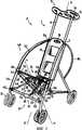
На фиг.1 представлено раскладывание двух задних ножек самонесущей детской складной прогулочной коляски, предназначенной для удерживания и перевозки ребенка.Figure 1 shows the folding of the two rear legs of a self-supporting child folding stroller designed to hold and transport the child.
Такая коляска содержит центральную стойку 1, блок 3 скольжения, скользящий по центральной стойке 1 вдоль оси Х-Х', две складных ножки 5 и сочлененную конструкцию 7 для одновременного раскладывания этих ножек.Such a stroller comprises a central strut 1, a sliding block 3 sliding along the central strut 1 along the axis X-X ', two folding legs 5 and an articulated structure 7 for simultaneously unfolding these legs.
Центральная стойка 1 содержит два штока 9, параллельных оси Х-Х'. Эти штоки 9 удерживаются в надлежащем месте (i) у их верхнего конца посредством рулевого колеса 11 и (ii) у их нижнего конца посредством опорной части 13.The Central rack 1 contains two rods 9 parallel to the axis X-X '. These rods 9 are held in place (i) at their upper end by means of the
Рулевое колесо 11 содержит часть 14 по существу овальной формы. Эта часть 14 снабжена тремя отверстиями 15, которые обеспечивают возможность простого придания направления детской складной прогулочной коляске, в частности, только одной рукой.The
Блок 3 скольжения содержит удлиненную часть по отношению к оси Х-Х', в которой просверлены два центральных отверстия 17, параллельных оси Х-Х'. Штоки 9 центральной стойки 1 проходят в отверстия 17 блока 3 скольжения. Таким образом, блок 3 скольжения может свободно скользить вдоль штоков 9 центральной стойки 1 между рулевым колесом 11 и опорной частью 13.Block 3 of the slide contains an elongated portion with respect to the axis X-X ', in which two
Кроме того, блок 3 скольжения имеет стопорные средства 18, выполненные, например, в виде фрикционного тормоза или механизма с защелкой. Эти стопорные средства 18 обеспечивают возможность стопорения блока 3 скольжения в месте, находящемся вблизи от любого из дальних концов его хода вдоль штоков 9 центральной стойки 1.In addition, the block 3 of the slide has a locking means 18, made, for example, in the form of a friction brake or mechanism with a latch. These locking means 18 provide the ability to lock the block 3 of the slide in a place located near any of the far ends of its course along the rods 9 of the Central rack 1.
Соответственно, два штока 9 обеспечивают стопорение блока 3 скольжения от вращения вокруг оси скольжения Х-Х'.Accordingly, two rods 9 lock the sliding block 3 against rotation about the sliding axis X-X '.
Как показано на фиг.1, ось Х-Х' несколько наклонена относительно вертикали, когда детская складная прогулочная коляска опирается на землю в разложенном положении.As shown in figure 1, the axis X-X 'is somewhat tilted relative to the vertical when the folding baby stroller rests on the ground in the unfolded position.
Каждая задняя ножка 5 коляски, показанной на фиг.1, имеет колесико 19 и ее складную конструкцию 7.Each rear leg 5 of the stroller shown in FIG. 1 has a
Складная конструкция 7 содержит, если смотреть по направлению Y-Y', отличающемуся от оси Х-Х', первый сочлененный треугольник 21 развертывания. Треугольник 21 на фиг.1 показан штрихпунктирной линией.The collapsible structure 7 comprises, when viewed in a direction Y-Y 'different from the axis X-X', a first jointed deployment triangle 21. Triangle 21 in FIG. 1 is shown by a dash-dot line.
Первая сторона 22 треугольника 21 развертывания прикреплена к центральной стойке 1. Она ограничена первым соединением 23, расположенным на опорной части 13, и вторым соединением 25, расположенным на блоке 3 скольжения.The
Треугольник 21 развертывания содержит вторую сторону 26, образованную соединительным стержнем 27, соединенным с блоком 3 скольжения вторым соединением 25.The deployment triangle 21 comprises a
Третья сторона 28 треугольника развертывания образована жесткой пластиной 29, присоединенной к опорной части 13 посредством первого соединения 23, и присоединенной посредством третьего соединения 31 к наружной стороне соединительного стержня 27, обращенной ко второму соединению 25.The
Жесткая пластина 29 по существу имеет треугольную форму. Для снижения веса конструкции в ней выполнен вырез.The
Первое соединение 23, соединяющее опорную часть 13 и жесткую пластину 29, содержит шарнир 33, проходящий вдоль оси Y-Y' по направлению с незначительным наклоном относительно горизонтали, когда детская прогулочная коляска опирается на землю в разложенном положении.The
Кроме того, ось Y-Y' составляет с осью Х-Х' угол, меньше 90°, чтобы обеспечить возможность развертывания ножек 5 в радиальном направлении относительно оси Х-Х' при раскладывании детской складной прогулочной коляски.In addition, the axis Y-Y 'makes an axis with the axis X-X', less than 90 °, so that the legs 5 can be deployed in the radial direction relative to the axis X-X 'when unfolding a child folding stroller.
Шарнир 33 содержит две точки 35 соединения, отделенные в направлении Y-Y'. Эти точки 35 расположены вблизи двух вершин жесткой пластины 29. Третье соединение 31 расположено вблизи третьей вершины пластины 29.The
В этом первом варианте осуществления конструкции 7 ножка 5 выполнена за одно целое с концом соединительного стержня 27, представляющего собой вторую сторону 26 треугольника 21 развертывания.In this first embodiment of the structure 7, the leg 5 is integral with the end of the connecting
Далее будет описано приведенное в качестве примера раскладывание конструкции 7 из сложенного положения в разложенное положение, показанное на фиг.1.Next, an example folding of the structure 7 from the folded position to the unfolded position shown in FIG. 1 will be described.
Вначале блок 3 скольжения крепят в верхнем положении вблизи рулевого колеса 11 с помощью стопорного средства 18.First, the sliding block 3 is mounted in the upper position near the
В этом положении соединительный стержень 27, образующий вторую сторону 26 треугольника 21 развертывания, и жесткая пластина 29, образующая третью сторону 28 треугольника 21 развертывания, расположены по существу параллельно оси Х-Х' центральной стойки 1.In this position, the connecting
В результате в этом положении треугольник 21 развертывания будет сплюснут. Ножка 5, жестко прикрепленная к удлинению соединительного стержня 27, находится в сложенном положении вблизи центральной стойки 1.As a result, in this position, the deployment triangle 21 will be flattened. Leg 5, rigidly attached to the extension of the connecting
Для того чтобы разложить задние ножки детской складной прогулочной коляски, освобождают стопорное средство 18. При этом блок 3 скольжения толкают вдоль оси Х-Х' к опорной части 13. Расстояние между первым соединением 23 и вторым соединением 25 по ходу перемещения уменьшается. В результате разность между (i) углом первой стороны 22 со второй стороной 26 треугольника 21 развертывания и (ii) углом первой стороны 22 с третьей стороной 28 треугольника 21 развертывания значительно увеличивается. Вершина треугольника развертывания, расположенная вблизи третьего соединения 31, перемещается в сторону от центральной стойки 1. В течение этого перемещения ножка 5, прикрепленная к удлинению соединительного стержня 27, отдаляется от центральной стойки 1.In order to expand the rear legs of the folding baby stroller, the locking means 18 is released. The sliding unit 3 is pushed along the axis X-X 'to the supporting
Когда блок 3 скольжения достигает своего нижнего положения вблизи опорной части 13 или входит в соприкосновение с ней, будет приведено в действие стопорное средство 18, и ножка 5 будет застопорена в разложенном положении.When the sliding unit 3 reaches its lower position near the supporting
В этом положении жесткая пластина 29 обеспечивает поддерживание треугольника 21 развертывания ножки 5, а также его периферийную жесткость по отношению к оси Х-Х' перемещения блока скольжения.In this position, the
Вторая конструкция 7А согласно изобретению, показанная на фиг.2-5, обеспечивает возможность развертывания каждой из передних ножек 5А детской складной прогулочной коляски. Конструкция 7А отличается от описанной выше конструкции 7 тем, что будет указано ниже.The
Как показано на фиг.2, третье соединение 31 между соединительным стержнем 27 второй стороны треугольника 21 развертывания и жесткой пластиной 29 расположено в промежуточной точке жесткой пластины 29.As shown in FIG. 2, a
Кроме того, ножка 5А присоединена к жесткой пластине 29 посредством четвертого соединения 41, расположенного вблизи от вершины жесткой пластины 29.In addition,
Складная конструкция 7А, соответствующая каждой ножке 5А, дополнительно содержит опорную часть 43, образованную вторым соединительным стержнем, который, с одной стороны, соединен посредством точки 44 блока 3 скольжения и, с другой стороны, посредством промежуточной точки 45 ножки 5А, расположенной ниже соединения 41. Как показано на фиг.2, опорная часть 43 проходит через отверстие 47 в жесткой пластине 29.The
Конструкция 7А образует псевдопараллелограмм, который имеет в качестве своих вершин (i) четвертое соединение 41 и промежуточную точку 45 ножки 5А и (ii) точку 44 блока 3 скольжения и середину шарнира 33.The
В отличие от первой конструкции 7 конструкция 7А дополнительно содержит опорные средства 49 для получения надежной складной конструкции и убираемые средства 51 придания жесткости.Unlike the first structure 7, the
Опорные средства 49 содержат для каждой ножки 5А пластину 53 удлиненной формы, изготовленную из гибкого материала. Такая гибкая пластина 53 с одной стороны прикреплена к первой точке 54 на верхней части блока 3 скольжения и с другой стороны ко второй точке 55 у верхнего конца ножки 5А вблизи точки 41 соединения ножки 5А и пластины 39. Длина гибкой пластины 53 по существу равна расстоянию отделения двух ее точек крепления, когда блок 3 скольжения расположен вблизи рулевого колеса 11. Таким образом, когда детская складная прогулочная коляска сложена, гибкая пластина 53 находится вблизи центральной стойки 1 в прямолинейном положении и по существу параллельно оси Х-Х', как показано на фиг.3.The support means 49 comprise, for each
Как показано на фиг.2, средства 51 придания жесткости содержат складной шток 61 и центральную соединительную часть 62.As shown in FIG. 2, the stiffening means 51 comprise a
Складной шток 61 содержит два плеча 63, связанных друг с другом посредством шарнира 65 вблизи первого конца. Противоположный от шарнира 65 конец каждого из плеч 63 соответствующим образом присоединен к двум передним ножкам 5А. Места соединения складного штока 61 с ножками 5А расположены вблизи колесиков 19 и определяют горизонтальное и поперечное направление, когда детская складная прогулочная коляска опирается на землю в разложенном положении.Folding
Связующее устройство 62 содержит «циркуль», составленный двумя соединенными пластинами 67 и 69. Первая пластина 67 соединена (i) с центральным шарниром 65 складного штока 61 и (ii) с опорной частью 13. Вторая пластина 69 одним концом соединена с промежуточной точкой первой пластины 67, а другим концом - с блоком 3 скольжения.The
Работа второй конструкции 7А подобна работе первой конструкции 7 с некоторыми различиями, которые указаны далее.The operation of the
Движение блока 3 скольжения к опорной части 13 вызывает движение ножки 5А в сторону от центральной стойки 1 под действием треугольника 21 развертывания. В течение этого движения выполненная в виде псевдопараллелограмма форма конструкции 7А обеспечивает удерживание оси ножки 5А по существу параллельно оси Х-Х', что благоприятно в отношении механической стойкости развернутой ножки.The movement of the sliding block 3 to the supporting
В разложенном положении опорная часть 43 подводит упорный блок к краю отверстия 47, чтобы увеличить жесткость конструкции.In the unfolded position, the
Геометрия конструкции 7А обеспечивает возможность получения отношения между (i) боковым отклонением от оси Х-Х' места соединения 41 между ножкой 5А и пластиной 39 и (ii) длиной хода блока 3 скольжения между рулевым колесом 11 и опорной частью 13, которое составляет меньше 1. При раскладывании детской складной прогулочной коляски расстояние, на которое отделены точки крепления гибких пластин 53, когда блок 3 скольжения находится вблизи опорной части 13, становится короче, чем расстояние, на которое эти точки отделены, когда блок 3 скольжения находится вблизи рулевого колеса 11. Отношение этих двух расстояний обычно находится в диапазоне от 0,85 до 0,95, а предпочтительно от 0,88 до 0,92.The geometry of
Таким образом, когда детская складная прогулочная коляска разложена, гибкие пластины 53 принимают положение значительного выгибания, как показано на фиг.2. Это положение обеспечивает возможность раскладывания надежной конструкции, поддерживаемой гибкими пластинами 53, как описано ниже.Thus, when the folding baby stroller is unfolded, the
Кроме того, отличие от первой конструкции 7, как показано на фиг.3, состоит в том, что складной шток 61 в начальном состоянии находится в сложенном положении. Перемещение блока 3 скольжения к опорной части 13 приводит к перемещению соединения между двумя пластинами 67 и 69 связующего устройства 62 в сторону от центральной стойки 1. В результате первая пластина 67 связующего устройства 62 обеспечивает движение центрального шарнира 65 складного штока 61 в сторону от центральной стойки 1. Когда блок 3 скольжения подходит близко к опорной части 13 или входит с ней в соприкосновение, складной шток 61 раскладывается и повышает периферийную жесткость двух ножек 5 относительно оси Х-Х', так что получается прочная рамная конструкция.In addition, the difference from the first structure 7, as shown in figure 3, is that the
В этом положении складной шток 61 предназначен для того, чтобы обеспечивать опору для ступней ребенка. Кроме того, между двумя ножками 5А параллельно первому складному штоку 61 закреплена полоса 70, обеспечивающая поддерживание сиденья детской прогулочной коляски.In this position, the
Альтернативно, как показано на фиг.4, у ножек 5 параллельно первому складному штоку 61 может быть присоединен второй складной шток 71, подобный штоку 61. При этом связующее устройство 62 содержит третий шток 73, присоединенный (i) к центральному шарниру 75 второго складного штока 71 и (ii) в промежуточной точке первой пластины 67 связующего устройства 62 либо непосредственно к шарниру 65.Alternatively, as shown in FIG. 4, at the legs 5, a second
Кроме того, развертывание второго складного штока 71 идентично развертыванию первого складного штока 61. В разложенном положении второй складной шток 71 предназначен для поддерживания сиденья детской складной прогулочной коляски.In addition, the deployment of the
Еще в одном альтернативном варианте (не показан) можно выполнить более легкую конструкцию посредством замены жесткой пластины 29 на вилку с двумя ветвями. В этом случае две точки соединения 35 будут расположены вблизи концов, обращенных к двум ветвям, а третье соединение 31 будет расположено вблизи общего конца двух ветвей вилки.In yet another alternative embodiment (not shown), a lighter construction can be achieved by replacing the
Напротив, когда жесткость предпочтительнее легкости, жесткая пластина 29 может быть сплошной, так что поверхность, ограниченная двумя точками 35 соединения и третьим соединением 31, будет сплошной, возможно, за исключением отверстия 47, через которое проходит опорная часть 43.On the contrary, when stiffness is preferable to lightness, the
Наконец, еще в одном варианте (не показан) вторую сторону треугольника развертывания выполняют посредством жесткой пластины, подсоединенной к блоку скольжения. В этом случае третью сторону треугольника развертывания выполняют из простого соединительного стержня, связывающего опорную часть с жесткой пластиной.Finally, in yet another embodiment (not shown), the second side of the deployment triangle is performed by means of a rigid plate connected to the sliding block. In this case, the third side of the deployment triangle is made of a simple connecting rod connecting the supporting part with the rigid plate.
На фиг.5 представлена самонесущая детская складная прогулочная коляска согласно альтернативному варианту, показанному на фиг.4 и снабженному сиденьем 81. Последнее удерживается (i) вторым складным штоком 71 и (ii) фиксирующими средствами (не показаны) на блоке 3 скольжения.Fig. 5 shows a self-supporting baby folding stroller according to an alternative embodiment shown in Fig. 4 and provided with a seat 81. The latter is held (i) by a
Кроме того, к блоку 3 скольжения прикреплена спинка 83 детской складной прогулочной коляски. Покрытие 85 для защиты ребенка удерживается двумя гибкими пластинами 53 и двумя подобными гибкими пластинами 86, закрепленными между верхней частью блока 3 скольжения и задними ножками 5. Покрытие 85 содержит две боковые оболочки 87, каждая из которых закреплена вдоль соответствующих пластин 53 и 86. Для завершения защиты ребенка между пластинами 86 закреплена задняя оболочка (не показана). Как вариант, к детской складной прогулочной коляске могут быть прикреплены вспомогательные принадлежности, такие как передний, отгибаемый и убираемый чехол или конструкция для хранения.In addition, the back 83 of the folding baby stroller is attached to the sliding block 3. The child protection cover 85 is held by two
Еще в одном варианте (не показан) к одному или более из штоков 9 может быть добавлен пружинный механизм, связывающий блок 3 скольжения с центральной стойкой 1 для обеспечения автоматического раскладывания конструкции (или, напротив, ее складывание) посредством простого расстопоривания блока 3 скольжения.In another embodiment (not shown), a spring mechanism can be added to one or more of the rods 9, connecting the sliding block 3 with the central rack 1 to ensure automatic folding of the structure (or, conversely, its folding) by simply opening the sliding block 3.
Благодаря описанному изобретению можно получить конструкцию, которая будет представлять собой легко складываемую конструкцию. Эта конструкция также будет иметь преимущество, заключающееся в обеспечении в разложенном положении периферийной жесткости ножки, несущей колесо (для детской складной прогулочной коляски), используя легко осуществимые, недорогие и легкие средства.Thanks to the described invention, it is possible to obtain a structure that will be an easily collapsible structure. This design will also have the advantage of providing in the unfolded position the peripheral stiffness of the leg supporting the wheel (for a child folding stroller) using easily feasible, inexpensive and lightweight means.
Центральное рулевое колесо 14 может быть легко приспособлено к такой конструкции и позволяет легко выполнять маневрирование самонесущей складной детской прогулочной коляской.The
Такой тип системы легко может быть приспособлен для других типов конструкций, включая, но не ограничиваясь этим, легкую детскую коляску для двойни, игрушечные детские складные стулья на колесиках, высокие стулья, откидные стулья, стулья на колесиках для лиц с физическими недостатками либо для других самонесущих тележек, например тележек для гольфа.This type of system can easily be adapted to other types of structures, including, but not limited to, a lightweight baby carriage for twins, toy baby folding chairs on wheels, high chairs, folding chairs, chairs on wheels for people with physical disabilities or for other self-supporting carts, such as golf carts.
Claims (15)
Translated fromRussianApplications Claiming Priority (2)
| Application Number | Priority Date | Filing Date | Title |
|---|---|---|---|
| FR0300535 | 2003-01-17 | ||
| FR0300535AFR2850073B1 (en) | 2003-01-17 | 2003-01-17 | DEPLOYABLE SEAT |
Publications (2)
| Publication Number | Publication Date |
|---|---|
| RU2005126045A RU2005126045A (en) | 2006-01-27 |
| RU2329910C2true RU2329910C2 (en) | 2008-07-27 |
Family
ID=32605848
Family Applications (1)
| Application Number | Title | Priority Date | Filing Date |
|---|---|---|---|
| RU2005126045/11ARU2329910C2 (en) | 2003-01-17 | 2004-01-16 | Folding structural system |
Country Status (13)
| Country | Link |
|---|---|
| US (1) | US7445228B2 (en) |
| EP (1) | EP1583679A2 (en) |
| JP (1) | JP2006514903A (en) |
| KR (1) | KR20050103278A (en) |
| CN (1) | CN1756685A (en) |
| AU (1) | AU2004205541A1 (en) |
| BR (1) | BRPI0406787A (en) |
| CA (1) | CA2513565A1 (en) |
| FR (1) | FR2850073B1 (en) |
| MX (1) | MXPA05007624A (en) |
| PL (1) | PL377819A1 (en) |
| RU (1) | RU2329910C2 (en) |
| WO (1) | WO2004065193A2 (en) |
Cited By (2)
| Publication number | Priority date | Publication date | Assignee | Title |
|---|---|---|---|---|
| RU2673911C2 (en)* | 2013-09-13 | 2018-12-03 | Бэбизен | Foldable pushchair suitable for transporting newborns |
| RU2829581C1 (en)* | 2024-08-06 | 2024-10-31 | Общество с ограниченной ответственностью "Эйри" | Folding stroller (versions) |
Families Citing this family (24)
| Publication number | Priority date | Publication date | Assignee | Title |
|---|---|---|---|---|
| CA2579746A1 (en)* | 2004-09-16 | 2006-03-23 | Mutsy B.V. | Mobile frame for a buggy |
| CN101410287B (en)* | 2006-04-03 | 2013-05-08 | 葛莱儿婴儿产品股份有限公司 | Stroller brake system |
| US7950684B2 (en)* | 2006-10-25 | 2011-05-31 | Jaimie Borisoff | Wheelchair side guards |
| US20080211206A1 (en)* | 2007-02-19 | 2008-09-04 | Thorne Henry F | Stroller |
| EP1970282A1 (en)* | 2007-03-15 | 2008-09-17 | Team-Tex | Device for transporting a child |
| WO2009131582A1 (en)* | 2008-04-24 | 2009-10-29 | Rick Shapiro | Fold flat support structure assemblies featuring simplified latches and releases |
| JP5361095B2 (en)* | 2008-08-29 | 2013-12-04 | グッドベイビー チャイルド プロダクツ カンパニー リミテッド | stroller |
| WO2010028235A1 (en) | 2008-09-05 | 2010-03-11 | Thorley Industries , Llc | Collapsible stroller |
| USD617239S1 (en)* | 2008-10-14 | 2010-06-08 | Cosco Management, Inc. | Stroller seat |
| USD615909S1 (en)* | 2009-09-04 | 2010-05-18 | Thorley Industries, Llc | Collapsible stroller |
| US8167332B2 (en)* | 2010-08-26 | 2012-05-01 | Sentiment Industries Ltd. | Folding stroller |
| US9216755B2 (en) | 2012-03-30 | 2015-12-22 | Kolcraft Enterprises, Inc. | Foldable strollers |
| US8911015B2 (en) | 2013-03-05 | 2014-12-16 | Yochanan Cohen | Car seat |
| US9487110B2 (en) | 2014-03-05 | 2016-11-08 | Pidyon Controls Inc. | Car seat |
| US10220734B2 (en) | 2013-03-05 | 2019-03-05 | Pidyon Controls Inc. | Car seat |
| US9333977B2 (en) | 2013-09-20 | 2016-05-10 | Radio Flyer Inc. | Multipurpose wagon |
| US9616782B2 (en) | 2014-08-29 | 2017-04-11 | Pidyon Controls Inc. | Car seat vehicle connection system, apparatus, and method |
| AU2016262487B2 (en) | 2015-05-12 | 2020-02-13 | Pidyon Controls Inc. | Car seat and connection system |
| CN109715473B (en) | 2016-07-27 | 2022-03-04 | 考可拉夫特公司 | Stroller with removable seat and related method |
| EP3490874A4 (en) | 2016-07-27 | 2020-04-15 | Kolcraft Enterprises, Inc. | Foldable strollers and related methods |
| US10994763B2 (en) | 2016-07-27 | 2021-05-04 | Kolcraft Enterprises, Inc. | Foldable strollers with removeable seats and related methods |
| DE102017104407B4 (en)* | 2017-03-02 | 2018-11-08 | Wanzl Metallwarenfabrik Gmbh | Push handle unit |
| US11052934B2 (en) | 2017-07-27 | 2021-07-06 | Kolcraft Enterprises, Inc. | Foldable strollers and related methods |
| CN111252132B (en)* | 2020-02-19 | 2024-11-29 | 好孩子儿童用品有限公司 | Child cart |
Citations (3)
| Publication number | Priority date | Publication date | Assignee | Title |
|---|---|---|---|---|
| FR2349485A2 (en)* | 1976-04-26 | 1977-11-25 | Perego Pines Spa | CHILDREN'S CAR, CALLED STROLLER, FOLDABLE AND SHORTENABLE |
| EP0000437A1 (en)* | 1977-07-07 | 1979-01-24 | Andrews Maclaren Limited | Foldable chair frame |
| US6367823B1 (en)* | 1998-06-11 | 2002-04-09 | Satsuki Co., Ltd. | Walking aid |
Family Cites Families (11)
| Publication number | Priority date | Publication date | Assignee | Title |
|---|---|---|---|---|
| BE793645A (en)* | 1972-01-03 | 1973-07-03 | Lines Walter M | WHEEL STROLLER |
| IT1005425B (en)* | 1974-01-24 | 1976-08-20 | Giordani Raffaele | STROLLER FOR CHILDREN WITH REDUCABLE SIZE |
| JPS5311441A (en)* | 1976-07-17 | 1978-02-01 | Kasai Kk | One touch opening mechanism of folding baby carriage |
| JPS5444914Y2 (en)* | 1976-08-19 | 1979-12-24 | ||
| US4386790A (en)* | 1980-03-10 | 1983-06-07 | Kassai Kabushikikaisha | Baby carriage |
| FR2564405A1 (en)* | 1984-05-17 | 1985-11-22 | Laune Pierre | Foldable structure for hand-manoeuvrable transport vehicle. |
| FR2566357B1 (en)* | 1984-06-22 | 1988-04-08 | Ampafrance | FOLDING STROLLER FOR CHILDREN |
| NL1012334C2 (en)* | 1999-06-15 | 2000-12-18 | Maxi Miliaan Bv | Stroller. |
| GB2363832B (en)* | 2000-06-20 | 2004-02-04 | Red Lan | Stoller having a break device |
| GB0022104D0 (en)* | 2000-09-08 | 2000-10-25 | Crisp David | Collapsible pushchair/carrier |
| JP3980349B2 (en)* | 2001-12-25 | 2007-09-26 | コンビ株式会社 | stroller |
- 2003
- 2003-01-17FRFR0300535Apatent/FR2850073B1/ennot_activeExpired - Fee Related
- 2004
- 2004-01-16PLPL377819Apatent/PL377819A1/enunknown
- 2004-01-16CNCNA2004800057004Apatent/CN1756685A/enactivePending
- 2004-01-16USUS10/542,604patent/US7445228B2/ennot_activeExpired - Lifetime
- 2004-01-16BRBR0406787-8Apatent/BRPI0406787A/ennot_activeIP Right Cessation
- 2004-01-16RURU2005126045/11Apatent/RU2329910C2/ennot_activeIP Right Cessation
- 2004-01-16JPJP2006500332Apatent/JP2006514903A/enactivePending
- 2004-01-16EPEP04702768Apatent/EP1583679A2/enactivePending
- 2004-01-16KRKR1020057013276Apatent/KR20050103278A/ennot_activeWithdrawn
- 2004-01-16MXMXPA05007624Apatent/MXPA05007624A/ennot_activeApplication Discontinuation
- 2004-01-16AUAU2004205541Apatent/AU2004205541A1/ennot_activeAbandoned
- 2004-01-16WOPCT/IB2004/000762patent/WO2004065193A2/enactiveApplication Filing
- 2004-01-16CACA002513565Apatent/CA2513565A1/ennot_activeAbandoned
Patent Citations (3)
| Publication number | Priority date | Publication date | Assignee | Title |
|---|---|---|---|---|
| FR2349485A2 (en)* | 1976-04-26 | 1977-11-25 | Perego Pines Spa | CHILDREN'S CAR, CALLED STROLLER, FOLDABLE AND SHORTENABLE |
| EP0000437A1 (en)* | 1977-07-07 | 1979-01-24 | Andrews Maclaren Limited | Foldable chair frame |
| US6367823B1 (en)* | 1998-06-11 | 2002-04-09 | Satsuki Co., Ltd. | Walking aid |
Cited By (2)
| Publication number | Priority date | Publication date | Assignee | Title |
|---|---|---|---|---|
| RU2673911C2 (en)* | 2013-09-13 | 2018-12-03 | Бэбизен | Foldable pushchair suitable for transporting newborns |
| RU2829581C1 (en)* | 2024-08-06 | 2024-10-31 | Общество с ограниченной ответственностью "Эйри" | Folding stroller (versions) |
Also Published As
| Publication number | Publication date |
|---|---|
| FR2850073B1 (en) | 2006-03-17 |
| CA2513565A1 (en) | 2004-08-05 |
| EP1583679A2 (en) | 2005-10-12 |
| BRPI0406787A (en) | 2006-01-17 |
| MXPA05007624A (en) | 2006-05-25 |
| AU2004205541A2 (en) | 2004-08-05 |
| US7445228B2 (en) | 2008-11-04 |
| AU2004205541A1 (en) | 2004-08-05 |
| FR2850073A1 (en) | 2004-07-23 |
| RU2005126045A (en) | 2006-01-27 |
| JP2006514903A (en) | 2006-05-18 |
| KR20050103278A (en) | 2005-10-28 |
| CN1756685A (en) | 2006-04-05 |
| WO2004065193A3 (en) | 2004-11-04 |
| US20060208461A1 (en) | 2006-09-21 |
| PL377819A1 (en) | 2006-02-20 |
| WO2004065193A2 (en) | 2004-08-05 |
Similar Documents
| Publication | Publication Date | Title |
|---|---|---|
| RU2329910C2 (en) | Folding structural system | |
| US9815487B2 (en) | Compact foldable stroller with one-handed fold control | |
| US9561817B2 (en) | Stroller with telescopic and locking members | |
| CN1982137B (en) | Collapsible supporting structure | |
| US8366141B2 (en) | Transporter | |
| US8360461B2 (en) | Foldable stroller | |
| CN103702890B (en) | collapsible pushchair | |
| CN102372017B (en) | Stroller with articulating structure | |
| US20060125211A1 (en) | Foldable chassis for baby carriages | |
| NO750170L (en) | ||
| US20060267303A1 (en) | Collapsible supporting structure | |
| KR20220052306A (en) | push-pull wagon | |
| US20080088115A1 (en) | Wheeled tail platform for a stroller | |
| US20140159346A1 (en) | Stroller with expandable cargo area | |
| CA2971656A1 (en) | Collapsible kick-scooter vehicle | |
| JPH0223164B2 (en) | ||
| EP2700559B1 (en) | Foldable stroller frame | |
| IL262375A (en) | Single pushchair that can be converted into a tandem pushchair that is practical to use | |
| US20080185029A1 (en) | Fold-up canopy for a people carrier, such as a perambulator or stroller | |
| CN210680888U (en) | Folding chassis of children's article and children's shallow | |
| US20070013167A1 (en) | Collapsible seat with a collapsible protective structure | |
| CN218806049U (en) | Stroller frame with adjustable backrest angle and convenient to fold and stroller | |
| AU2006202465A1 (en) | Collapsible supporting structure |
Legal Events
| Date | Code | Title | Description |
|---|---|---|---|
| MM4A | The patent is invalid due to non-payment of fees | Effective date:20090117 |