RU2321718C1 - Multilateral well construction method - Google Patents
Multilateral well construction methodDownload PDFInfo
- Publication number
- RU2321718C1 RU2321718C1RU2006136651/03ARU2006136651ARU2321718C1RU 2321718 C1RU2321718 C1RU 2321718C1RU 2006136651/03 ARU2006136651/03 ARU 2006136651/03ARU 2006136651 ARU2006136651 ARU 2006136651ARU 2321718 C1RU2321718 C1RU 2321718C1
- Authority
- RU
- Russia
- Prior art keywords
- casing
- deflector
- pipe
- casing pipe
- technological
- Prior art date
Links
Images
Landscapes
- Consolidation Of Soil By Introduction Of Solidifying Substances Into Soil (AREA)
Abstract
Description
Translated fromRussianИзобретение относится к нефтегазодобывающей промышленности, а именно к строительству кустов нефтяных и газовых скважин в залежах тяжелой нефти.The invention relates to the oil and gas industry, namely the construction of bushes of oil and gas wells in heavy oil deposits.
Известен способ строительства многоствольной скважины (патент RU № 2256763, МПК Е21В 7/08, опубл. в бюл. № 20 от 20.07.2005), включающий спуск в обсадную колонну колонны труб, на конце которой расположен отклонитель, вскрытие обсадной колонны в требуемом интервале, чередование спуска в колонну труб гибкой трубы с соплом до входа под действием отклонителя в окна обсадной колонны, подачу жидкости под давлением через гибкую трубу с соплом с одновременным поступательным движением для формирования технологических каналов до необходимой длины с извлечением гибкой трубы и поворотом колонны труб с отклонителем на необходимый угол до получения необходимого числа дополнительных стволов, после чего гибкую трубу окончательно извлекают из обсадной колонны, при этом вскрытие в обсадной колонне осуществляют по всему диаметру и на необходимую длину в требуемом интервале, после чего отклонитель устанавливают в зоне вскрытия, а гибкую колонну с соплом после формирования дополнительного ствола перед поворотом колонны труб с отклонителем извлекают только из зоны вскрытия обсадной колонны.A known method of constructing a multilateral well (patent RU No. 2256763, IPC ЕВВ 7/08, published in Bulletin No. 20 of 07/20/2005), including the descent into the casing of the pipe string, at the end of which there is a diverter, opening the casing in the required interval , alternating the descent into the pipe string of the flexible pipe with the nozzle before entering under the action of the deflector into the casing windows, supplying liquid under pressure through the flexible pipe with the nozzle with simultaneous translational movement to form the technological channels to the required length with extraction flexible pipe and turning the pipe string with the diverter to the required angle until the required number of additional shafts is obtained, after which the flexible pipe is finally removed from the casing, and the opening in the casing is carried out over the entire diameter and to the required length in the required interval, after which the diverter is installed in the opening zone, and the flexible column with the nozzle after the formation of the additional barrel before turning the pipe string with the diverter is removed only from the opening zone of the casing.
Наиболее близким по технической сущности и достигаемому результату является способ строительства многоствольной скважины (патент RU № 2259457, МПК Е21В 7/06, опубл. в бюл. № 24 от 27.08.2005 г.), включающий спуск в обсадную колонну в требуемый интервал колонны труб, на конце которой расположен отклонитель, спуск в колонну труб гибкого вала с фрезой на конце до взаимодействия с отклонителем, вращение с поступательным перемещением гибкого вала с фрезой, которая в результате взаимодействия с отклонителем прорезает окна в обсадной колонне и входит в пласт на заданное расстояние с получением технологических каналов, извлечение гибкого вала с фрезой из скважины, спуск в колонну труб гибкой трубы с соплом до входа под действием отклонителя в окна обсадной колонны, подача жидкости под давлением через гибкую трубу с соплом с одновременным поступательным движением для увеличения технологических каналов до необходимой длины, при этом после спуска колонны труб с отклонителем в требуемый интервал отклонитель фиксируют относительно обсадной колонны с возможностью последовательного поворота на определенный угол при каждом возвратно-поступательном движении колонны труб, далее после спуска в колонну труб гибкого вала с фрезой чередуют прорезание окна в обсадной колонне с получением технологического канала и извлечение фрезы прорезанного окна с поворотом отклонителя на заданный угол при возвратно-поступательном движении колонны труб до завершения кругового цикла, затем после спуска в колонну труб гибкой трубы с соплом чередуют увеличение технологического канала до необходимой длины под действием жидкости, подаваемой под давлением в гибкую трубу с соплом, и извлечение сопла из окна обсадной колонны с поворотом отклонителя на заданный угол при возвратно-поступательном движении колонны труб до завершения кругового цикла.The closest in technical essence and the achieved result is a method of constructing a multilateral well (patent RU No. 2259457, IPC ЕВВ 7/06, published in Bulletin No. 24 of 08/27/2005), which includes descent into the casing in the required interval of the pipe string at the end of which there is a deflector, descent into the string of pipes of a flexible shaft with a mill at the end before interacting with the deflector, rotation with the translational movement of the flexible shaft with a mill, which, as a result of interaction with the deflector, cuts through the windows in the casing and enters the formation and a predetermined distance with obtaining technological channels, removing a flexible shaft with a cutter from the well, lowering a flexible pipe with a nozzle into the pipe string before entering under the action of a deflector into the casing windows, supplying liquid under pressure through a flexible pipe with a nozzle with simultaneous translational movement to increase technological channels to the required length, while after the descent of the pipe string with the diverter into the required interval, the diverter is fixed relative to the casing with the possibility of sequential rotation on the predetermined angle for each reciprocating movement of the pipe string, then after the flexible shaft with the cutter is lowered into the pipe string, the window is cut in the casing to obtain the process channel and the cutter of the slotted window is turned with the deflector rotated by a predetermined angle when the pipe string is reciprocated to the completion of the circular cycle, then after the descent into the pipe string of the flexible pipe with the nozzle, the process channel is increased alternately to the required length under the action of the liquid supplied under pressure into a flexible pipe with a nozzle, and removing the nozzle from the casing window with rotation of the deflector by a predetermined angle during the reciprocating movement of the pipe string until the end of the circular cycle.
Как аналогу, так и прототипу присущ общий недостаток, связанный с тем, что при строительстве такой конструкции многоствольной скважины в залежах тяжелой нефти необходимо строительство дополнительной скважины (добывающей или нагнетательной), что требует дополнительных материальных и финансовых затрат.Both the analogue and the prototype have a common disadvantage associated with the fact that during the construction of such a multilateral well design in heavy oil deposits, it is necessary to build an additional well (production or injection), which requires additional material and financial costs.
Технической задачей предлагаемого изобретения является сокращение материальных и финансовых затрат, связанных с исключением строительства дополнительной скважины в залежах тяжелой нефти.The technical task of the invention is to reduce material and financial costs associated with the exclusion of the construction of an additional well in heavy oil deposits.
Техническая задача решается способом строительства многоствольной скважины, включающим спуск в обсадную колонну в требуемый интервал колонны труб, на конце которой расположен отклонитель, фиксируемый относительно труб с возможностью последовательного поворота на определенный угол, прорезание фрезой обсадной колонны, последовательное формирование по периметру обсадной колонны технологических каналов необходимой длины при помощи гибкой трубы с соплом на конце, через которые подают жидкость под давлением, формируя по периметру ряд технологических каналов.The technical problem is solved by the method of constructing a multilateral well, including a descent into the casing in the required interval of the pipe string, at the end of which there is a deflector, fixed relative to the pipes with the possibility of sequential rotation at a certain angle, cutting the casing with a mill, and sequential formation of the technological channels necessary lengths using a flexible pipe with a nozzle at the end through which fluid is supplied under pressure, forming a series of t hnologicheskih channels.
Новым является то, что прорезание обсадной колонны фрезой производят перед спуском отклонителя по всему ее периметру в двух местах в пределах одного продуктивного пласта, а отклонитель фиксируют в обсадной колонне так, чтобы выходные отверстия технологических каналов располагались в пределах одной прорези обсадной колонны, после извлечения гибкой трубы с соплом отклонитель освобождают от соединения с обсадной колонной и фиксируют ниже или выше первоначальной установки с возможностью последовательного поворота на определенный угол и формирование аналогично первому ряду дополнительного ряда технологических каналов в пределах второй прорези обсадной колонны, после извлечения колонны труб с отклонителем в обсадную колонну спускают технологическую колонну труб и устанавливают пакер между рядами технологических каналов в межтрубном пространстве между обсадной колонной и технологической колонной труб.What is new is that the cutter is cut through the casing before the deflector is run around its entire perimeter in two places within the same reservoir, and the deflector is fixed in the casing so that the outlet holes of the technological channels are located within the same cut of the casing, after the flexible pipes with a nozzle diverter release from the connection with the casing and fix below or above the initial installation with the possibility of sequential rotation at a certain angle and the formation is similar to the first row of an additional row of technological channels within the second cut of the casing, after removing the pipe string with a diverter into the casing, the pipe string is lowered and a packer is installed between the rows of technological channels in the annulus between the casing and the pipe string.
На фигуре 1 изображена схема предлагаемого способа строительства многоствольной скважины.The figure 1 shows a diagram of the proposed method for the construction of a multilateral well.
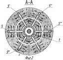
На фигуре 2 изображено сечение А-А верхнего ряда технологических каналов.The figure 2 shows a section aa of the upper row of technological channels.
В обсадную колонну 1 (см. фиг.1) в требуемый интервал спускают фрезу (на фиг.1 и 2 не показано) и производят прорезание обсадной колонны 1 в двух местах с образованием прорезей 2 и 3 в обсадной колонне 1 в пределах одного продуктивного пласта 4, после чего в обсадную колонну 1 производят спуск колонны труб с отклонителем на конце (на фиг.1 и 2 не показано).A cutter is lowered into the casing 1 (see FIG. 1) at the required interval (not shown in FIGS. 1 and 2) and the
Затем отклонитель фиксируют относительно обсадной колонны 1 с возможностью его поворота на требуемый угол (например, 60°) в обсадной колонне 1 так, чтобы выходные отверстия технологических каналов (на фиг.1 и 2 не показано) отклонителя располагались в пределах одной из прорези, например прорези 2 обсадной колонны 1.Then the diverter is fixed relative to the
Потом в колонну труб спускают гибкие трубы с соплом до взаимодействия последнего под действием отклонителя со вскрытым участком прорези 2 обсадной колонны 1. Далее подают жидкость под давлением через гибкую трубу с соплом с одновременным поступательным движением, в результате образуется технологический канал 5, который увеличивают до необходимой длины L.Then, flexible pipes with a nozzle are lowered into the pipe string until the latter interacts under the action of the deflector with the exposed section of the casing 2 slot 2. Next, liquid is supplied under pressure through a flexible pipe with the nozzle with simultaneous translational movement, as a result, a
После чего гибкую трубу с соплом извлекают из технологического канала 5. Затем колонну труб приподнимают на заданную высоту и опускают в исходное положение, в результате отклонитель поворачивается на вышеуказанный угол, например 60° (см. фиг.2). Далее, сочетая извлечение гибкой трубы с соплом с поворотом отклонителя на требуемый угол до завершения кругового цикла, получают ряд 6 технологических каналов 5′; 5′′; 5′′′...5n требуемой длины в заданном интервале по всему периметру вскрытого участка прорези 2 обсадной колонны 1.Then the flexible pipe with the nozzle is removed from the
После извлечения гибкой трубы с соплом из обсадной колонны 1 отклонитель освобождают от соединения с обсадной колонной 1 и фиксируют его ниже или выше первоначальной установки с возможностью последовательного поворота на определенный угол (например, ниже), так чтобы выходные отверстия технологических каналов (на фиг.1 и 2 не показано) отклонителя располагались в пределах другой прорези 3 обсадной колонн 1 в пределах одного продуктивного пласта 4. Потом в колонну труб спускают гибкие трубы с соплом до взаимодействия последнего под действием отклонителя со вскрытым участком прорези 3 обсадной колонны 1. Далее подают жидкость под давлением через гибкую трубу с соплом с одновременным поступательным движением, в результате образуется технологический канал 7, который увеличивают до необходимой длины.After removing the flexible pipe with the nozzle from the
После этого гибкую трубу с соплом извлекают из технологического канала 6. Затем колонну труб приподнимают на заданную высоту и опускают в исходное положение, в результате отклонитель поворачивается на вышеуказанный угол, например 60°. Далее, сочетая извлечение гибкой трубы с соплом с поворотом отклонителя на требуемый угол до завершения кругового цикла, получают дополнительный ряд 8 технологические каналы 7′; 7′′′; 7′′′...7n требуемой длины в заданном интервале по всему периметру вскрытого участка прорези 3 обсадной колонны 1. После этого сначала извлекают гибкую трубу с соплом из обсадной колонны 1, а затем колонну труб с отклонителем.After that, the flexible pipe with the nozzle is removed from the technological channel 6. Then the pipe string is raised to a predetermined height and lowered to its original position, as a result, the deflector is rotated by the above angle, for example 60 °. Further, combining the extraction of the flexible pipe with the nozzle with the rotation of the deflector to the required angle until the end of the circular cycle, an additional row of 8 process channels 7 ′ is obtained; 7 ′ ′ ′; 7 '''... 7n the desired length in a predetermined range around the perimeter of the exposed portion of the slot 3 of the
Далее в обсадную колонну 1 спускают технологическую колонну труб 9 и устанавливают пакер 10 между рядами 6 и 8 технологических каналов 5; 5′; 5′′; 5′′′...5n и 7; 7′; 7′′; 7′′′...7n соответственно в межтрубном пространстве 11 между обсадной колонной 1 и технологической колонной труб 9.Next, the casing string 9 is lowered into the
Далее спускают в технологическую колонну труб 9 насос 12 любой известной конструкции, предпочтительно винтовой. После чего с устья скважины нагнетают теплоноситель (горячий водяной пар) в межтрубное пространство 11, который, достигнув прорези 2 обсадной колонны 1, попадает в ряд 6, технологические каналы 4; 4′; 4′′; 4′′′...4n, по которым распространяется вглубь продуктивного пласта 4. После прогрева продуктивного пласта 4 до определенной температуры запускают насос 12 в работу.Next, the pump 12 of any known design, preferably a screw, is lowered into the process pipe string 9. Then, from the wellhead, coolant (hot water vapor) is pumped into the annulus 11, which, having reached the slot 2 of the
Разогревание происходит по всей высоте продуктивного пласта 4, радиально направленно от каждого технологического канала 5; 5′; 5′′; 5′′′...5n ряда 6, при этом горячий водяной пар не должен прорываться в технологические каналы 7; 7′; 7′′; 7′′′...7n дополнительного ряда 8, что определяется расчетным путем.Heating takes place along the entire height of the reservoir 4, radially directed from each
Разогретый продукт (тяжелая вязкая нефть) продуктивного пласта попадает в технологические каналы 7; 7′; 7′′; 7′′′...7n дополнительного ряда 8 и сквозь прорезь 3 обсадной колонны 1 поступает внутрь обсадной колонны 1 на прием насоса 12, который перекачивает разогретую тяжелую вязкую нефть на дневную поверхность.The heated product (heavy viscous oil) of the reservoir falls into the technological channels 7; 7 ′; 7 ′ ′; 7 ′ ′ ′ ... 7n of additional row 8 and through the slot 3 of the
В процессе перекачки на дневную поверхность разогретой тяжелой вязкой нефти исключается ее попадание в межколонное пространство 11 и ее контакт с теплоносителем благодаря пакеру 10.During the pumping onto the day surface of the heated heavy viscous oil, its entry into the annular space 11 and its contact with the coolant due to the packer 10 are excluded.
Использование предлагаемого способа за счет формирования дополнительного ряда технологических каналов в пределах одного продуктивного пласта позволяет с помощью одной скважины как производить закачку теплоносителя в продуктивный пласт, так и производить добычу разогретой тяжелой вязкой нефти из нее, что дает возможность сэкономить материальные и финансовые средства, исключив строительство дополнительной скважины.Using the proposed method due to the formation of an additional number of technological channels within the same reservoir allows using one well both to pump coolant into the reservoir and to produce heated heavy viscous oil from it, which makes it possible to save material and financial resources, excluding construction additional well.
Claims (1)
Translated fromRussianPriority Applications (1)
| Application Number | Priority Date | Filing Date | Title |
|---|---|---|---|
| RU2006136651/03ARU2321718C1 (en) | 2006-10-16 | 2006-10-16 | Multilateral well construction method |
Applications Claiming Priority (1)
| Application Number | Priority Date | Filing Date | Title |
|---|---|---|---|
| RU2006136651/03ARU2321718C1 (en) | 2006-10-16 | 2006-10-16 | Multilateral well construction method |
Publications (1)
| Publication Number | Publication Date |
|---|---|
| RU2321718C1true RU2321718C1 (en) | 2008-04-10 |
Family
ID=39366767
Family Applications (1)
| Application Number | Title | Priority Date | Filing Date |
|---|---|---|---|
| RU2006136651/03ARU2321718C1 (en) | 2006-10-16 | 2006-10-16 | Multilateral well construction method |
Country Status (1)
| Country | Link |
|---|---|
| RU (1) | RU2321718C1 (en) |
Citations (7)
| Publication number | Priority date | Publication date | Assignee | Title |
|---|---|---|---|---|
| US5036918A (en)* | 1989-12-06 | 1991-08-06 | Mobil Oil Corporation | Method for improving sustained solids-free production from heavy oil reservoirs |
| RU2006561C1 (en)* | 1992-01-09 | 1994-01-30 | Евгений Петрович Кислицин | Device for collaring supplementary shaft |
| RU2074944C1 (en)* | 1994-06-07 | 1997-03-10 | Тагир Тимерханович Латыпов | Drilling and supporting of multiface well |
| US5862863A (en)* | 1996-08-26 | 1999-01-26 | Swisher; Mark D. | Dual completion method for oil/gas wells to minimize water coning |
| US6119780A (en)* | 1997-12-11 | 2000-09-19 | Camco International, Inc. | Wellbore fluid recovery system and method |
| RU2232263C2 (en)* | 2002-05-27 | 2004-07-10 | ООО "ЛУКОЙЛ-Коми" | Method for extracting of high-viscosity oil |
| RU2259457C1 (en)* | 2004-03-31 | 2005-08-27 | Открытое акционерное общество "Татнефть" им. В.Д. Шашина | Multilateral well construction method |
- 2006
- 2006-10-16RURU2006136651/03Apatent/RU2321718C1/ennot_activeIP Right Cessation
Patent Citations (7)
| Publication number | Priority date | Publication date | Assignee | Title |
|---|---|---|---|---|
| US5036918A (en)* | 1989-12-06 | 1991-08-06 | Mobil Oil Corporation | Method for improving sustained solids-free production from heavy oil reservoirs |
| RU2006561C1 (en)* | 1992-01-09 | 1994-01-30 | Евгений Петрович Кислицин | Device for collaring supplementary shaft |
| RU2074944C1 (en)* | 1994-06-07 | 1997-03-10 | Тагир Тимерханович Латыпов | Drilling and supporting of multiface well |
| US5862863A (en)* | 1996-08-26 | 1999-01-26 | Swisher; Mark D. | Dual completion method for oil/gas wells to minimize water coning |
| US6119780A (en)* | 1997-12-11 | 2000-09-19 | Camco International, Inc. | Wellbore fluid recovery system and method |
| RU2232263C2 (en)* | 2002-05-27 | 2004-07-10 | ООО "ЛУКОЙЛ-Коми" | Method for extracting of high-viscosity oil |
| RU2259457C1 (en)* | 2004-03-31 | 2005-08-27 | Открытое акционерное общество "Татнефть" им. В.Д. Шашина | Multilateral well construction method |
Similar Documents
| Publication | Publication Date | Title |
|---|---|---|
| RU2407884C1 (en) | Development method of heavy oil or bitumen mine field with control of well production extraction | |
| RU2442883C1 (en) | Method for development of high-viscosity oil reserves | |
| RU2459934C1 (en) | Development method of multilayer non-homogeneous oil deposit | |
| RU2410534C1 (en) | Method and device for development of heavy oil or bitumen deposit by using two-head horizontal wells | |
| RU2412342C1 (en) | Procedure for development of deposit of heavy oil or bitumen with control of pumping heat carrier into well | |
| RU2339808C1 (en) | Method for extraction of heavy and high viscous hydrocarbons out of underground deposit | |
| RU2433254C1 (en) | Method of oil filed development | |
| RU2339807C1 (en) | Method of extraction of heavy and high viscous hydrocarbons from undeground deposits | |
| RU2413068C1 (en) | Development method of heavy oil or bitumen mine field with control of well production extraction | |
| RU2333340C1 (en) | Method of construction of multi-shaft well for recovery of high-viscosous oil | |
| RU2411356C1 (en) | Method and arrangement for development of deposit of heavy oil or bitumen with control over withdrawal of well production | |
| RU2321718C1 (en) | Multilateral well construction method | |
| US7290608B2 (en) | Method and system for pumping in an oil well | |
| RU2526047C1 (en) | Development of extra-heavy crude oil | |
| RU2434129C1 (en) | Procedure for development of high viscous oil deposit | |
| RU2483205C1 (en) | Development method of heavy oil or bitumen mine field with control of heat carrier pumped to well | |
| RU2004126073A (en) | METHOD FOR DEVELOPING DEPOSITS OF BITUMEN AND HIGH VISCOUS OILS AND THE COMPLEX SYSTEM OF EQUIPMENT, THEIR EQUIPMENT FOR ITS IMPLEMENTATION (OPTIONS) | |
| RU2315168C1 (en) | Method for multilateral well construction | |
| RU2412343C1 (en) | Method for development of deposit of heavy oil or bitumen with control over withdrawal of well production | |
| RU2595032C1 (en) | Downhole pump unit for production of bituminous oil | |
| RU2318973C1 (en) | Multilateral well construction method | |
| RU2315166C1 (en) | Well construction method | |
| RU2584467C1 (en) | Method of developing high-viscosity oil field | |
| RU2333338C1 (en) | Method of construction of multi-shaft well for recovery of high-viscosous oil | |
| RU2350744C1 (en) | Method of operating double-head well |
Legal Events
| Date | Code | Title | Description |
|---|---|---|---|
| MM4A | The patent is invalid due to non-payment of fees | Effective date:20151017 |