RU2316898C1 - Method for simultaneous measurement of frequency dependencies of doppler frequency shift and time of expansion of short-wave signals in ionospheric radio line - Google Patents
Method for simultaneous measurement of frequency dependencies of doppler frequency shift and time of expansion of short-wave signals in ionospheric radio lineDownload PDFInfo
- Publication number
- RU2316898C1 RU2316898C1RU2006124071/09ARU2006124071ARU2316898C1RU 2316898 C1RU2316898 C1RU 2316898C1RU 2006124071/09 ARU2006124071/09 ARU 2006124071/09ARU 2006124071 ARU2006124071 ARU 2006124071ARU 2316898 C1RU2316898 C1RU 2316898C1
- Authority
- RU
- Russia
- Prior art keywords
- frequency
- signal
- time
- radio
- systems
- Prior art date
Links
Images

Landscapes
- Radar Systems Or Details Thereof (AREA)
Abstract
Description
Translated fromRussianИзобретение относится к радиотехнике и электросвязи и может быть использовано в системах частотного обеспечения коротковолновой (KB) радиосвязи для оперативного измерения основных параметров ионосферных линий связи и выбора оптимальных радиоканалов.The invention relates to radio engineering and telecommunications and can be used in systems for the frequency supply of short-wave (KB) radio communications for the operational measurement of the main parameters of ionospheric communication lines and the selection of optimal radio channels.
Надежность и качество голосовых и дискретных систем KB радиосвязи в первую очередь зависит от условий распространения сигналов в ионосферной радиолинии и помеховой обстановки. К наиболее важным особенностям ионосферной радиолинии, которые накладывают ограничения на использование высокоскоростных и широкополосных систем KB радиосвязи, относятся следующие ее основные свойства: многолучевость, обусловленная слоистой структурой ионосферы и магнитоионным расщеплением распространяющихся волн; частотные и временные вариации, обусловленные зависимостью показателя преломления ионосферы от частоты и времени. Влияние этих основных свойств ионосферной радиолинии на сигналы систем KB радиосвязи зависит от длины и географического расположения радиотрассы, диаграммы направленности передающей и приемной антенн, отношения центральной частоты излучаемого сигнала к максимально применимой частоте (МПЧ), которая, в свою очередь, зависит от времени суток, времени года, солнечной активности и протяженности радиотрассы. Параметры каждого приходящего луча испытывают быстрые флуктуации из-за движения неоднородностей, а также медленные флуктуации из-за изменения освещенности ионосферы. Наряду с этим вследствие движения слоев наблюдается доплеровский сдвиг частоты и вследствие движения неоднородностей - доплеровское уширение спектра сигнала. Дифференциальный доплеровский сдвиг между лучами на данной рабочей частоте приводит к интенсивным замираниям и значительным частотно-селективным помехам особенно высокоскоростным (широкополосным) системам связи. Даже относительно малые величины частотно-селективных и быстрых временных замираний распространения, приводят к неустраняемым (даже за счет повышения мощности сигнала) ошибкам.The reliability and quality of voice and discrete KB radio systems primarily depends on the propagation conditions of the signals in the ionospheric radio link and the interference environment. The most important features of the ionospheric radio line, which impose restrictions on the use of high-speed and broadband KB radio communication systems, include its following basic properties: multipath due to the layered structure of the ionosphere and magnetoionic splitting of propagating waves; frequency and time variations due to the dependence of the refractive index of the ionosphere on frequency and time. The influence of these basic properties of the ionospheric radio line on the signals of KB radio communication systems depends on the length and geographical location of the radio path, the radiation pattern of the transmitting and receiving antennas, the ratio of the central frequency of the emitted signal to the maximum applicable frequency (MFC), which, in turn, depends on the time of day, season, solar activity and the length of the radio path. The parameters of each incoming ray undergo rapid fluctuations due to the motion of inhomogeneities, as well as slow fluctuations due to changes in the illumination of the ionosphere. Along with this, due to the motion of the layers, a Doppler frequency shift is observed, and due to the motion of inhomogeneities, a Doppler broadening of the signal spectrum is observed. The differential Doppler shift between beams at a given operating frequency leads to intense fading and significant frequency-selective interference, especially to high-speed (broadband) communication systems. Even relatively small values of frequency-selective and fast temporal fading of propagation lead to unrecoverable (even due to an increase in signal power) errors.
В связи с этим для повышения эффективности современных систем KB радиосвязи необходимо постоянно знать условия распространения сигналов в ионосферной радиолинии между передающей и приемной станциями. Для этого организуют диагностику ионосферной радиолинии путем передачи «зондирующих» сигналов и их соответствующей обработки в приемнике, в результате которой определяют качество прохождения сигнала на каждой радиолинии и в каждом заданном радиоканале в конкретный момент времени. В настоящее время существует много способов диагностики ионосферной радиолинии, использующих в качестве зондирующих шумоподобные сигналы (ШПС или сложные) различной частотно-временной структуры. Применение таких сигналов позволяет существенно повысить помехозащищенность и разрешающую способность способов и систем диагностики. Из большого многообразия используемых для диагностики ионосферных радиолиний ШПС самое широкое распространение в настоящее время имеет непрерывный линейно частотно-модулированный (ЛЧМ) сигнал.In this regard, in order to increase the efficiency of modern KB radio communication systems, it is necessary to constantly know the conditions for the propagation of signals in the ionospheric radio link between the transmitting and receiving stations. To do this, they organize the diagnosis of the ionospheric radio line by transmitting "probe" signals and their corresponding processing at the receiver, as a result of which the quality of signal transmission on each radio line and in each given radio channel at a particular time is determined. Currently, there are many methods for diagnosing an ionospheric radio line using noise-like signals (SHPS or complex) of various time-frequency structures as probing. The use of such signals can significantly increase the noise immunity and resolution of diagnostic methods and systems. Of the wide variety of ShPS used for the diagnosis of ionospheric radio links, the continuous linearly frequency-modulated (LFM) signal is currently the most widely used.
Известен способ одновременного определения зависимостей времени группового запаздывания и доплеровского смещения частоты от частоты излучения отдельных мод распространения KB с помощью периодических сигналов с линейной частотной модуляцией [Иванов В.А., Колчев А.А., Шумаев В.В. Влияние нестационарности однолучевого КВ-канала на характеристики сигналов с расширенным спектром. // Проблемы распространения и дифракции электромагнитных волн: М. МФТИ. 1994. С.73-79]. Недостатком этого способа является большое время измерения на одной частоте и, как следствие, большой частотный шаг между измерениями.A known method for simultaneously determining the dependences of the group delay time and Doppler frequency shift on the radiation frequency of individual KB propagation modes using periodic signals with linear frequency modulation [Ivanov VA, Kolchev AA, Shumaev VV The effect of unsteadiness of a single-beam HF channel on the characteristics of signals with a spread spectrum // Problems of propagation and diffraction of electromagnetic waves: M. MIPT. 1994. S. 73-79]. The disadvantage of this method is the large measurement time at one frequency and, as a consequence, the large frequency step between measurements.
Способ одновременного определения доплеровского смещения частоты и времени группового запаздывания отдельных мод на основе трехэлементного ЛЧМ сигнала изложен в работе [Pool A.W.V. Advanced sounding The FMCW alternative // Radio Science /. - 1985. - V.20, №6. - P.1609-1616]. Использование фазовых измерений в этом способе позволяет уменьшить время измерения в одном частотном канале. Однако и в этом случае измерения производятся дискретно, в заранее заданных каналах при помощи трех сдвинутых во времени ЛЧМ сигналов с жестко заданными параметрами.A method for simultaneously determining the Doppler frequency offset and group delay time of individual modes based on a three-element LFM signal is described in [Pool A.W.V. Advanced sounding The FMCW alternative // Radio Science /. - 1985. - V.20, No. 6. - P.1609-1616]. Using phase measurements in this method reduces the measurement time in one frequency channel. However, in this case, the measurements are performed discretely, in predetermined channels using three time-shifted chirp signals with hard-set parameters.
Предлагаемое изобретение устраняет эти недостатки, позволяя проводить одновременные измерения доплеровского смещения частоты и времени группового запаздывания отдельных мод в произвольных каналах декаметрового диапазона радиоволн путем использования двойного непрерывного ЛЧМ сигнала.The present invention eliminates these disadvantages, allowing simultaneous measurements of the Doppler frequency offset and group delay time of individual modes in arbitrary channels of the decameter range of radio waves by using a double continuous LFM signal.
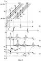
Способ состоит в следующем. Передатчик излучает одновременно два непрерывных ЛЧМ сигнала с одинаковыми параметрами: начальные частота и фаза, скорость изменения частоты. Различие состоит в начальном времени излучения: один сигнал смещен относительно другого на время Т (см. фиг.1а).The method is as follows. The transmitter emits simultaneously two continuous LFM signals with the same parameters: the initial frequency and phase, the rate of change of frequency. The difference lies in the initial radiation time: one signal is shifted relative to the other by a time T (see figa).
Если первый ЛЧМ сигнал а1(t) имеет вид:If the first chirp signal a1 (t) has the form:

где fH - начальная частота излучения;where fH is the initial radiation frequency;

a0 - амплитуда излучаемого сигнала;a0 is the amplitude of the emitted signal;
t - текущее время;t is the current time;
t0 - время начала излучения;t0 - radiation start time;
tK - длительность излучения,tK - radiation duration,
то для второго сигнала в выражении (1) изменяется только время начала излучения:then for the second signal in expression (1) only the time of the onset of radiation changes:

Обработка принятого ЛЧМ сигнала в приемнике методом сжатия в частотной области состоит в умножении его на сигнал гетеродина, комплексно-сопряженный излучаемому сигналу, и в анализе спектра полученного сигнала разностной частоты. Для первого излученного сигнала этим операциям соответствуют следующие математические соотношения:Processing the received LFM signal in the receiver by the compression method in the frequency domain consists of multiplying it by a local oscillator signal complex conjugate to the emitted signal and analyzing the spectrum of the received difference frequency signal. For the first radiated signal, the following mathematical relations correspond to these operations:
A1(t)=a1вых(t)·a1*(t)A1 (t) = a1 out (t) · a1 * (t)

где A1(t) - сигнал разностной частоты, соответствующий первому излученному сигналу;where A1 (t) is the difference frequency signal corresponding to the first radiated signal;
S1( Ω) - его спектр;S1 (Ω) is its spectrum;
Ω - круговая частота; Ω is the circular frequency;
a1вых (t) - сигнал а1(t) на выходе из ионосферной радиолинии (на входе приемника);a1out (t) is the signal a1 (t) at the output of the ionospheric radio line (at the input of the receiver);
а1*(t) - сигнал, комплексно-сопряженный сигналу а1(t).and1 * (t) is the signal complex conjugate to the signal a1 (t).
Для определения времени группового запаздывания отдельных мод распространения KB сигнал разностной частоты разбивается на N элементов длительностью TЭ с шагом между элементами ΔTЭ и для каждого элемента вычисляется преобразование Фурье [Иванов В.А., Рябова Н.В., Шумаев В.В. Основы радиотехнических систем ДКМ диапазона: Учебное пособие. - Йошкар-Ола: МарГТУ, 1998, - с.155-159]. В излучаемом сигнале каждому элементу будет соответствовать ЛЧМ сигнал с полосой

Чтобы найти спектр первого элемента разностного сигнала, используем подход, основанный на представлении среды распространения передаточной функцией H(ω, t), которую в случае многолучевого нестационарного канала распространения можно представить в виде:To find the spectrum of the first element of the difference signal, we use an approach based on the representation of the propagation medium by the transfer function H (ω, t), which in the case of a multipath non-stationary propagation channel can be represented as:

где |Нi(ω, t)| - модуль передаточной функции отдельного луча;where | Hi (ω, t) | - module transfer function of a single beam;
ω=2πf;ω = 2πf;
φi(ω, t) - набег фазы отдельного луча в ионосферной радиолинии;φi (ω, t) is the phase incursion of an individual beam in the ionospheric radio line;
m - число мод распространения.m is the number of propagation modes.
Элемент зондирующего сигнала занимает некоторую полосу
φi(ω, t)≈φi(ω0, t0)+φ′it(ω0, t0)Δt+φ′iω(ω0, t0)Δω,φi (ω, t) ≈φi (ω0 , t0 ) + φ ′it (ω0 , t0 ) Δt + φ ′iω (ω0 , t0 ) Δω,

где

|Hoi| - постоянное значение модуля передаточной функции отдельного луча.| Hoi | - constant value of the transfer function of a single beam.
Известен физический смысл коэффициентов разложения фазы (5). Так первая производная по частоте для i-й моды равна времени группового запаздывания сигнала этой моды τi:The physical meaning of the phase decomposition coefficients is known (5). So the first frequency derivative for the i-th mode is equal to the group delay time of the signal of this mode τi :

Зависимость фазы сигнала i-й моды от времени связана с доплеровским смещением частоты этой моды F∂i:The time dependence of the signal phase of the i-th mode is related to the Doppler frequency shift of this mode F∂i :

Квазистационарность канала и отсутствие частотной дисперсии предполагают, что в полосе частот элемента сигнала за время его длительности τi(ω; t) и F∂i(ω; t) не изменяются, т.е. τi(ω; t)=τi(ω0; t0)=τoi=const и F∂i(ω; t)=F∂i(ω0; t0)=F∂io=const, где τoi и F∂io - постоянные значения времени запаздывания и доплеровского смещения частоты i-го луча.The quasistationarity of the channel and the absence of frequency dispersion suggest that in the frequency band of the signal element during its duration τi (ω; t) and F∂i (ω; t) do not change, i.e. τi (ω; t) = τi (ω0 ; t0 ) = τoi = const and F∂i (ω; t) = F∂i (ω0 ; t0 ) = F∂io = const, where τoi and F∂io are constant values of the delay time and Doppler frequency shift of the i-th beam.
При обработке методом сжатия в частотной области длительность элемента сигнала ТЭ при спектральном анализе много больше времени запаздывания сигнала в ионосферном радиоканале: ТЭ>>τoi. Тогда А1(t), с учетом (3), можно записать в виде:When processing by compression in the frequency domain of the signal element duration TE the spectral analysis is much greater than the signal delay time in the ionospheric RB: TE >> τoi. Then A1 (t), taking into account (3), can be written in the form:

где

Как видно из (8) отдельный элемент разностного сигнала на протяжении ТЭ представляет собой отрезок гармонического колебания. С учетом этого S1( Ω) можно записать в виде:As can be seen from (8), a separate element of the difference signal during TЭ E is a segment of harmonic oscillation. With this in mind, S1 (Ω) can be written as:

где sinc(x), как функция переменной х, определяется соотношением
Если для второго излученного сигнала записать аналогичные соотношениям (3) преобразования:If, for the second emitted signal, write the transformations similar to (3):
A2(t)=a2вых(t)·a2*(t)A2 (t) = a2 out (t) · a2 * (t)

где A2(t) - сигнал разностной частоты, соответствующий второму излученному сигналу; S2( Ω) - его спектр; a2вых(t) - сигнал a2(t) на выходе из ионосферы, то для спектра первого элемента его разностного сигнала получим:where A2 (t) is the difference frequency signal corresponding to the second radiated signal; S2 (Ω) is its spectrum; a2out (t) is the signal a2 (t) at the exit from the ionosphere, then for the spectrum of the first element of its difference signal we get:

Сравнивая (9) и (11), видим, что в этих выражениях амплитуды совпадают, а различаются только фазыi.Comparing (9) and (11), we see that in these expressions the amplitudes coincide, and only phasesi differ.
Модули |S1( Ω)| и |S2( Ω)| имеют максимумы на частотах


Если в результате многолучевости в точку приема одновременно приходит несколько лучей с разной задержкой τoi, то каждому из них будет соответствовать своя разностная частота (см. фиг.1б и фиг.2а, где Fi - разностная частота различных мод распространения). При этом разрешающая способность по частоте δF при спектральной обработке сигнала длительностью ТЭ задается соотношениемIf, as a result of multipath, several beams simultaneously arrive at the receiving point with different delays τoi , then each of them will have its own difference frequency (see Fig. 1b and Fig. 2a, where Fi is the difference frequency of different propagation modes). In this case, the frequency resolution δF in the spectral processing of a signal of duration TE is given by

Отсюда разрешающая способность по задержке δτ будет равна:Hence, the delay resolution δτ will be equal to:

Если Δψi - разность фаз между спектральными составляющими Ωoi для S2( Ω) и S1( Ω), то, с учетом (4) и (7), имеем:If Δψi is the phase difference between the spectral components Ωoi for S2 (Ω) and S1 (Ω), then, taking into account (4) and (7), we have:

Из (13) следует, чтоIt follows from (13) that

Смещение Т необходимо выбирать таким образом, чтобы |ΔψI|=|2πF∂ioT|∈(0; π). ТогдаThe displacement T must be chosen so that | ΔψI | = | 2πF∂io T | ∈ (0; π). Then

При ионосферном распространении KB обычно выполняется условие F∂io<10 Гц. Следовательно, Т<0,05 с.In the ionospheric propagation of KB, the condition F∂io <10 Hz is usually satisfied. Therefore, T <0.05 s.
Рассмотрим предлагаемый способ по диаграммам фиг.2, на которой представлены основные процедуры и этапы обработки принимаемого сигнала и измерения доплеровского смещения частоты и времени распространения элемента двойного ЛЧМ сигнала на выходе диагностируемой ионосферной радиолинии. На фиг.2а толстыми линиями изображен один элемент двойного непрерывного ЛЧМ сигнала с длительностью ТЭ, диапазоном частот ΔfЭ и центральной частотой f0K, а тонкими линиями изображен многолучевой сигнал на выходе ионосферной радиолинии, состоящий из трех сигналов с различными временами распространения τ1÷τ3 и доплеровскими смещениями частоты F∂1÷F∂3. Здесь же показаны частоты F1÷F3 «сжатых» в частотной области трех разностных сигналов, получаемых в результате перемножения принимаемого сигнала с сигналом гетеродина приемника, комплексно сопряженному излучаемому сигналу и выделения низкочастотной составляющей. Проводя одинаковое разбиение как двойного непрерывного ЛЧМ сигнала (см. фиг.1а), так и каждого разностного сигнала, как показано на фиг.2б (здесь Т - время задержки второго ЛЧМ сигнала относительно первого), и выполняя преобразования Фурье для каждого элемента, получаем две последовательности спектральных отсчетов. Эти отсчеты являются комплексными числами, что дает возможность определить амплитуду и фазу спектральных составляющих каждого элемента разностного сигнала.Consider the proposed method according to the diagrams of figure 2, which shows the basic procedures and steps for processing the received signal and measuring the Doppler frequency offset and propagation time of the element of the double LFM signal at the output of the diagnosed ionospheric radio line. Thick lines 2a depicts one element continuous double chirped signal of duration Te, Δf frequency rangeE and the center frequency f0K, depicted as thin lines multipath signal output ionospheric radio link consisting of three signals with different propagation times τ1 ÷ τ3 and Doppler frequency shifts F∂1 ÷ F∂3 . Also shown here are the frequencies F1 ÷ F3 “compressed” in the frequency domain of three difference signals obtained by multiplying the received signal with the receiver local oscillator signal, a complex conjugate of the emitted signal, and isolation of the low-frequency component. Carrying out the same splitting of both the double continuous LFM signal (see Fig. 1a) and each difference signal, as shown in Fig. 2b (here T is the delay time of the second LFM signal relative to the first), and performing Fourier transforms for each element, we obtain two sequences of spectral readings. These samples are complex numbers, which makes it possible to determine the amplitude and phase of the spectral components of each element of the difference signal.
Для определения времени группового запаздывания используется амплитудный спектр разностного сигнала. Частоты Ωoki, на которых наблюдаются максимумы модуля спектра k-го элемента сигнала разностной частоты, соответствуют задержкам различных мод распространенияTo determine the group delay time, the amplitude spectrum of the difference signal is used. The frequencies Ωoki , at which the maxima of the spectrum modulus of the kth element of the difference frequency signal are observed, correspond to the delays of various propagation modes

на частотеat frequency

На фиг.2в показаны спектры сжатых в частотной области каждого из элементов ЛЧМ сигнала с центральной частотой f0k на выходе ионосферной радиолинии. Для элемента первого ЛЧМ сигнала согласно (9) в случае трех принимаемых сигналов (мод) имеем три спектральные составляющие вида

находится по формуле:found by the formula:

На фиг.2г для элемента двойного ЛЧМ сигнала с центральной частотой f0k в координатной системе доплеровского смещения частоты и времени распространения сигнала показана процедура отображения (регистрации) результатов совместной обработки спектров разностных сигналов. Время распространения сигнала (группового запаздывания) различных мод пропорционально частотам максимума модуля спектра разностного сигнала
Регистрируя изменения в положении максимумов модуля спектра сигнала разностной частоты (см. фиг.2в) от элемента к элементу при изменении рабочей частоты от fH до fK, получаем частотную зависимость времени группового запаздывания τki(f0k) (ионограмма) для диагностируемой ионосферной радиолинии (см. фиг.1б). Ионограмма представляет собой трехмерное изображение данных ЛЧМ диагностики. По горизонтали откладывается частота в диапазоне от 2 до 30 МГц, по вертикали - время распространения τ (время группового запаздывания). Третье измерение - мощность сигнала для каждого частотного элемента в дБ относительно заданного уровня.By registering changes in the position of the maxima of the modulus of the spectrum of the signal of the difference frequency (see Fig. 2c) from element to element when the operating frequency changes from fH to fK , we obtain the frequency dependence of the group delay time τki (f0k ) (ionogram) for the diagnosed ionospheric radio lines (see figb). An ionogram is a three-dimensional image of chirp data. The frequency in the range from 2 to 30 MHz is plotted horizontally, and the propagation time τ (group delay time) vertically. The third measurement is the signal power for each frequency element in dB relative to a given level.
Вычисляя по формуле (14) значение F∂ik для каждого элемента сигнала, получаем частотную зависимость доплеровского смещения частоты F∂ik = F∂i(f0k) (доплерограмма) для диагностируемой ионосферной радиолинии (см. фиг.1в). Доплерограмма представляет собой трехмерное изображение результатов вычисления предлагаемым способом. По горизонтали откладывается частота в диапазоне от 2 до 30 МГц, по вертикали - доплеровское смещение частоты для каждой моды распространения. Третьим измерением также выступает мощность сигнала.Calculating the value of F∂ik for each signal element using formula (14), we obtain the frequency dependence of the Doppler frequency shift F∂ik = F∂i (f0k ) (Doppler) for the diagnosed ionospheric radio line (see Fig. 1c). Dopplerogram is a three-dimensional image of the calculation results of the proposed method. The frequency in the range from 2 to 30 MHz is plotted horizontally, and the Doppler frequency offset for each propagation mode is plotted vertically. The third dimension is also the signal strength.
Следовательно, в диапазоне частот от fH до fK для каждой принимаемой моды сигнала определяются последовательности F∂i(f0k) и τi(f0k). Важным преимуществом предлагаемого способа одновременного измерения доплеровского смещения частоты и времени распространения сигнала в ионосферной радиолинии с применением двойного непрерывного ЛЧМ сигнала состоит в том, что параметры разбиения разностного сигнала TЭ, ΔTЭ(ΔfЭ) являются параметрами обработки принятого непрерывного ЛЧМ сигнала и могут быть выбраны произвольным образом, не изменяя исходной структуры излучаемого сигнала, что позволяет определить F∂i и τi, для любой интересующей нас рабочей частоты fp.Therefore, in the frequency range from fH to fK, for each received signal mode, the sequences F∂i (f0k ) and τi (f0k ) aredetermined . An important advantage of the proposed method for simultaneously measuring the Doppler frequency offset and propagation time of a signal in the ionospheric radio line using a double continuous LFM signal is that the difference signal splitting parameters TE , ΔTE (ΔfE ) are the processing parameters of the received continuous LFM signal and can be are chosen arbitrarily, without changing the initial structure of the emitted signal, which allows us to determine F∂i and τi for any working frequency of interest to us fp .
Таким образом, применение предлагаемого способа в системах диагностики ионосферных радиолиний непрерывным ЛЧМ сигналом в отличие от известного позволит оперативно получать частотные зависимости доплеровского смещения частоты и времени распространения сигнала в ионосферной радиолинии во всем ДКМ диапазоне радиоволн, на основании которых обеспечиваются устойчивые высокоскоростные и гибкие каналы передачи информации для существующих систем KB радиосвязи.Thus, the application of the proposed method in the diagnostic systems of ionospheric radio links by a continuous chirp signal, in contrast to the known one, will allow one to quickly obtain frequency dependences of the Doppler frequency offset and propagation time of a signal in the ionospheric radio line in the entire DCM band of radio waves, based on which stable high-speed and flexible information transmission channels are provided for existing KB radio systems.
Claims (1)
Translated fromRussian

Priority Applications (1)
| Application Number | Priority Date | Filing Date | Title |
|---|---|---|---|
| RU2006124071/09ARU2316898C1 (en) | 2006-07-04 | 2006-07-04 | Method for simultaneous measurement of frequency dependencies of doppler frequency shift and time of expansion of short-wave signals in ionospheric radio line |
Applications Claiming Priority (1)
| Application Number | Priority Date | Filing Date | Title |
|---|---|---|---|
| RU2006124071/09ARU2316898C1 (en) | 2006-07-04 | 2006-07-04 | Method for simultaneous measurement of frequency dependencies of doppler frequency shift and time of expansion of short-wave signals in ionospheric radio line |
Publications (1)
| Publication Number | Publication Date |
|---|---|
| RU2316898C1true RU2316898C1 (en) | 2008-02-10 |
Family
ID=39266406
Family Applications (1)
| Application Number | Title | Priority Date | Filing Date |
|---|---|---|---|
| RU2006124071/09ARU2316898C1 (en) | 2006-07-04 | 2006-07-04 | Method for simultaneous measurement of frequency dependencies of doppler frequency shift and time of expansion of short-wave signals in ionospheric radio line |
Country Status (1)
| Country | Link |
|---|---|
| RU (1) | RU2316898C1 (en) |
Cited By (5)
| Publication number | Priority date | Publication date | Assignee | Title |
|---|---|---|---|---|
| RU2475962C2 (en)* | 2010-06-18 | 2013-02-20 | Открытое акционерное общество "Концерн "Созвездие" | Method to transfer and receive digital information in tropospheric communication lines |
| RU2483322C1 (en)* | 2012-02-03 | 2013-05-27 | Федеральное государственное казенное военное образовательное учреждение высшего профессионального образования "ВОЕННАЯ АКАДЕМИЯ СВЯЗИ имени Маршала Советского Союза С.М. Буденного" Министерства обороны Российской Федерации | Method for polarisation adaptation of short-wave radio lines operating with ionospheric waves (versions) |
| RU2565237C1 (en)* | 2014-08-07 | 2015-10-20 | Федеральное государственное бюджетное учреждение науки Тихоокеанский океанологический институт им. В.И. Ильичева Дальневосточного отделения Российской академии наук (ТОИ ДВО РАН) | Evaluation of complex signal carrier frequency doppler shift |
| RU186027U1 (en)* | 2018-10-03 | 2018-12-26 | Акционерное общество "Российский институт мощного радиостроения" | DEVICE FOR DOPPLER FREQUENCY DEFINITION DETERMINATION BY THE PHASOMANIPULATED SIGNAL INFORMATION BY THE WEIGHTED APPROXIMATION OF PHASE DEFLECTION |
| RU2687884C1 (en)* | 2018-06-14 | 2019-05-16 | Акционерное общество "Российский институт мощного радиостроения" (АО "РИМР") | Method for determining doppler frequency shift based on an information phase-manipulated signal based on analysis of deviation of phase difference 2 of order |
Citations (7)
| Publication number | Priority date | Publication date | Assignee | Title |
|---|---|---|---|---|
| EP0114463A2 (en)* | 1982-12-27 | 1984-08-01 | Rockwell International Corporation | Link quality analyser and method of link quality measurement |
| US4555806A (en)* | 1982-03-27 | 1985-11-26 | Rohde & Schwarz Gmbh & Co. Kg | System for the automatic establishment of a shortwave telegraphy signal connection |
| SU1178036A1 (en)* | 1983-01-31 | 1988-04-07 | Предприятие П/Я Р-6618 | Steering system for air-cushion vessel |
| SU1580577A1 (en)* | 1988-10-03 | 1990-07-23 | Пензенский Политехнический Институт | Simulator of multiple-beam radio communication channel |
| GB2253971A (en)* | 1984-10-30 | 1992-09-23 | Secr Defence | Ionospheric sounding system |
| RU2154910C2 (en)* | 1997-03-18 | 2000-08-20 | Жданов Борис Борисович | Computer-aided short-wave communications control system |
| RU2262802C1 (en)* | 2004-06-09 | 2005-10-20 | Федеральное государственное унитарное предприятие "Воронежский научно-исследовательский институт связи" | Device for transmitting and receiving broadband signals, modulated by phase and frequency |
- 2006
- 2006-07-04RURU2006124071/09Apatent/RU2316898C1/ennot_activeIP Right Cessation
Patent Citations (7)
| Publication number | Priority date | Publication date | Assignee | Title |
|---|---|---|---|---|
| US4555806A (en)* | 1982-03-27 | 1985-11-26 | Rohde & Schwarz Gmbh & Co. Kg | System for the automatic establishment of a shortwave telegraphy signal connection |
| EP0114463A2 (en)* | 1982-12-27 | 1984-08-01 | Rockwell International Corporation | Link quality analyser and method of link quality measurement |
| SU1178036A1 (en)* | 1983-01-31 | 1988-04-07 | Предприятие П/Я Р-6618 | Steering system for air-cushion vessel |
| GB2253971A (en)* | 1984-10-30 | 1992-09-23 | Secr Defence | Ionospheric sounding system |
| SU1580577A1 (en)* | 1988-10-03 | 1990-07-23 | Пензенский Политехнический Институт | Simulator of multiple-beam radio communication channel |
| RU2154910C2 (en)* | 1997-03-18 | 2000-08-20 | Жданов Борис Борисович | Computer-aided short-wave communications control system |
| RU2262802C1 (en)* | 2004-06-09 | 2005-10-20 | Федеральное государственное унитарное предприятие "Воронежский научно-исследовательский институт связи" | Device for transmitting and receiving broadband signals, modulated by phase and frequency |
Non-Patent Citations (1)
| Title |
|---|
| POOL A.W.V. Advanced sounding The FMCW alternativ. Radio Science. 1985, v.20, №6, p.1609-1616.* |
Cited By (5)
| Publication number | Priority date | Publication date | Assignee | Title |
|---|---|---|---|---|
| RU2475962C2 (en)* | 2010-06-18 | 2013-02-20 | Открытое акционерное общество "Концерн "Созвездие" | Method to transfer and receive digital information in tropospheric communication lines |
| RU2483322C1 (en)* | 2012-02-03 | 2013-05-27 | Федеральное государственное казенное военное образовательное учреждение высшего профессионального образования "ВОЕННАЯ АКАДЕМИЯ СВЯЗИ имени Маршала Советского Союза С.М. Буденного" Министерства обороны Российской Федерации | Method for polarisation adaptation of short-wave radio lines operating with ionospheric waves (versions) |
| RU2565237C1 (en)* | 2014-08-07 | 2015-10-20 | Федеральное государственное бюджетное учреждение науки Тихоокеанский океанологический институт им. В.И. Ильичева Дальневосточного отделения Российской академии наук (ТОИ ДВО РАН) | Evaluation of complex signal carrier frequency doppler shift |
| RU2687884C1 (en)* | 2018-06-14 | 2019-05-16 | Акционерное общество "Российский институт мощного радиостроения" (АО "РИМР") | Method for determining doppler frequency shift based on an information phase-manipulated signal based on analysis of deviation of phase difference 2 of order |
| RU186027U1 (en)* | 2018-10-03 | 2018-12-26 | Акционерное общество "Российский институт мощного радиостроения" | DEVICE FOR DOPPLER FREQUENCY DEFINITION DETERMINATION BY THE PHASOMANIPULATED SIGNAL INFORMATION BY THE WEIGHTED APPROXIMATION OF PHASE DEFLECTION |
Similar Documents
| Publication | Publication Date | Title |
|---|---|---|
| US20170131335A1 (en) | Coherent signal analyzer | |
| KR20160138065A (en) | A method in a radar system, a radar system and an apparatus of a radar system | |
| US20200355843A1 (en) | Method of free-field broadband calibration of hydrophone sensitivity based on pink noise | |
| RU2316898C1 (en) | Method for simultaneous measurement of frequency dependencies of doppler frequency shift and time of expansion of short-wave signals in ionospheric radio line | |
| CN109991590B (en) | System and method for testing low-frequency emission characteristic of transducer in pressure tank in limited space | |
| JP6179940B2 (en) | Doppler imaging signal transmitter, Doppler imaging signal receiver, Doppler imaging system and method | |
| CN112470023B (en) | Positioning method and positioning system for locating at least one object by using wave-based signals | |
| Jing et al. | Channel characterization of acoustic waveguides consisting of straight gas and water pipelines | |
| CN102647785A (en) | A method for distinguishing wireless transmission multipath in wireless signal strength ranging technology | |
| CN111586546B (en) | Method and system for measuring resonance point transmission response of low-frequency transducer | |
| CN105877783A (en) | Two-dimensional shear wave elastic imaging method and device | |
| KR20190135716A (en) | Active Radar Target Simulating Apparatus having multiple Antennas | |
| RU2539968C1 (en) | Differential-range method of determining coordinates of radio-frequency source | |
| JP5379312B2 (en) | Distance measuring device | |
| RU2330298C2 (en) | Method for detection of damage point in power transmission and communication lines and device for its implementation | |
| RU2565237C1 (en) | Evaluation of complex signal carrier frequency doppler shift | |
| Pakdel Azar et al. | Enhanced target detection using a new combined sonar waveform design | |
| CN114545357B (en) | Ionosphere Es layer high-resolution vertical detection method based on cross-spectral analysis | |
| RU2753829C1 (en) | Method for determining anechoic coefficient in radio frequency anechoic chamber and apparatus for implementation thereof | |
| RU2739478C1 (en) | Method for processing a pseudo-noise signal in sonar | |
| RU2499275C2 (en) | Multifrequency method of measuring absolute propagation time of chirp radio signals | |
| RU187712U1 (en) | A device for determining the error of tracking the time of arrival of a navigation radio signal during its propagation through artificial ionospheric formation | |
| US7164622B2 (en) | Acoustic propagation delay measurements using transmission of known broad bandwidth waveforms | |
| RU2727267C1 (en) | Method of measuring range under water at arbitrary position in horizontal plane longitudinal axis of receiving frame magnetic antenna | |
| CN110311722A (en) | A kind of satellite repeater local frequency calibration test method |
Legal Events
| Date | Code | Title | Description |
|---|---|---|---|
| MM4A | The patent is invalid due to non-payment of fees | Effective date:20080705 |